RU2500103C2 - Container system for blood and cartridge - Google Patents
Container system for blood and cartridge Download PDFInfo
- Publication number
- RU2500103C2 RU2500103C2 RU2011126336/14A RU2011126336A RU2500103C2 RU 2500103 C2 RU2500103 C2 RU 2500103C2 RU 2011126336/14 A RU2011126336/14 A RU 2011126336/14A RU 2011126336 A RU2011126336 A RU 2011126336A RU 2500103 C2 RU2500103 C2 RU 2500103C2
- Authority
- RU
- Russia
- Prior art keywords
- tube
- clamping device
- bag
- blood
- filter
- Prior art date
Links
Images

Classifications
-
- A—HUMAN NECESSITIES
- A61—MEDICAL OR VETERINARY SCIENCE; HYGIENE
- A61M—DEVICES FOR INTRODUCING MEDIA INTO, OR ONTO, THE BODY; DEVICES FOR TRANSDUCING BODY MEDIA OR FOR TAKING MEDIA FROM THE BODY; DEVICES FOR PRODUCING OR ENDING SLEEP OR STUPOR
- A61M1/00—Suction or pumping devices for medical purposes; Devices for carrying-off, for treatment of, or for carrying-over, body-liquids; Drainage systems
- A61M1/02—Blood transfusion apparatus
- A61M1/0209—Multiple bag systems for separating or storing blood components
- A61M1/0218—Multiple bag systems for separating or storing blood components with filters
-
- A—HUMAN NECESSITIES
- A61—MEDICAL OR VETERINARY SCIENCE; HYGIENE
- A61J—CONTAINERS SPECIALLY ADAPTED FOR MEDICAL OR PHARMACEUTICAL PURPOSES; DEVICES OR METHODS SPECIALLY ADAPTED FOR BRINGING PHARMACEUTICAL PRODUCTS INTO PARTICULAR PHYSICAL OR ADMINISTERING FORMS; DEVICES FOR ADMINISTERING FOOD OR MEDICINES ORALLY; BABY COMFORTERS; DEVICES FOR RECEIVING SPITTLE
- A61J1/00—Containers specially adapted for medical or pharmaceutical purposes
- A61J1/05—Containers specially adapted for medical or pharmaceutical purposes for collecting, storing or administering blood, plasma or medical fluids ; Infusion or perfusion containers
- A61J1/10—Bag-type containers
-
- A—HUMAN NECESSITIES
- A61—MEDICAL OR VETERINARY SCIENCE; HYGIENE
- A61M—DEVICES FOR INTRODUCING MEDIA INTO, OR ONTO, THE BODY; DEVICES FOR TRANSDUCING BODY MEDIA OR FOR TAKING MEDIA FROM THE BODY; DEVICES FOR PRODUCING OR ENDING SLEEP OR STUPOR
- A61M1/00—Suction or pumping devices for medical purposes; Devices for carrying-off, for treatment of, or for carrying-over, body-liquids; Drainage systems
- A61M1/02—Blood transfusion apparatus
- A61M1/0209—Multiple bag systems for separating or storing blood components
- A61M1/0218—Multiple bag systems for separating or storing blood components with filters
- A61M1/0227—Multiple bag systems for separating or storing blood components with filters and means for securing the filter against damage, e.g. during centrifugation
-
- A—HUMAN NECESSITIES
- A61—MEDICAL OR VETERINARY SCIENCE; HYGIENE
- A61M—DEVICES FOR INTRODUCING MEDIA INTO, OR ONTO, THE BODY; DEVICES FOR TRANSDUCING BODY MEDIA OR FOR TAKING MEDIA FROM THE BODY; DEVICES FOR PRODUCING OR ENDING SLEEP OR STUPOR
- A61M1/00—Suction or pumping devices for medical purposes; Devices for carrying-off, for treatment of, or for carrying-over, body-liquids; Drainage systems
- A61M1/02—Blood transfusion apparatus
- A61M1/029—Separating blood components present in distinct layers in a container, not otherwise provided for
-
- A—HUMAN NECESSITIES
- A61—MEDICAL OR VETERINARY SCIENCE; HYGIENE
- A61M—DEVICES FOR INTRODUCING MEDIA INTO, OR ONTO, THE BODY; DEVICES FOR TRANSDUCING BODY MEDIA OR FOR TAKING MEDIA FROM THE BODY; DEVICES FOR PRODUCING OR ENDING SLEEP OR STUPOR
- A61M1/00—Suction or pumping devices for medical purposes; Devices for carrying-off, for treatment of, or for carrying-over, body-liquids; Drainage systems
- A61M1/36—Other treatment of blood in a by-pass of the natural circulatory system, e.g. temperature adaptation, irradiation ; Extra-corporeal blood circuits
- A61M1/3621—Extra-corporeal blood circuits
- A61M1/3622—Extra-corporeal blood circuits with a cassette forming partially or totally the blood circuit
- A61M1/36222—Details related to the interface between cassette and machine
-
- A—HUMAN NECESSITIES
- A61—MEDICAL OR VETERINARY SCIENCE; HYGIENE
- A61M—DEVICES FOR INTRODUCING MEDIA INTO, OR ONTO, THE BODY; DEVICES FOR TRANSDUCING BODY MEDIA OR FOR TAKING MEDIA FROM THE BODY; DEVICES FOR PRODUCING OR ENDING SLEEP OR STUPOR
- A61M1/00—Suction or pumping devices for medical purposes; Devices for carrying-off, for treatment of, or for carrying-over, body-liquids; Drainage systems
- A61M1/36—Other treatment of blood in a by-pass of the natural circulatory system, e.g. temperature adaptation, irradiation ; Extra-corporeal blood circuits
- A61M1/3621—Extra-corporeal blood circuits
- A61M1/3622—Extra-corporeal blood circuits with a cassette forming partially or totally the blood circuit
- A61M1/36224—Extra-corporeal blood circuits with a cassette forming partially or totally the blood circuit with sensing means or components thereof
-
- A—HUMAN NECESSITIES
- A61—MEDICAL OR VETERINARY SCIENCE; HYGIENE
- A61M—DEVICES FOR INTRODUCING MEDIA INTO, OR ONTO, THE BODY; DEVICES FOR TRANSDUCING BODY MEDIA OR FOR TAKING MEDIA FROM THE BODY; DEVICES FOR PRODUCING OR ENDING SLEEP OR STUPOR
- A61M1/00—Suction or pumping devices for medical purposes; Devices for carrying-off, for treatment of, or for carrying-over, body-liquids; Drainage systems
- A61M1/36—Other treatment of blood in a by-pass of the natural circulatory system, e.g. temperature adaptation, irradiation ; Extra-corporeal blood circuits
- A61M1/3621—Extra-corporeal blood circuits
- A61M1/3622—Extra-corporeal blood circuits with a cassette forming partially or totally the blood circuit
- A61M1/36226—Constructional details of cassettes, e.g. specific details on material or shape
- A61M1/362265—Details of valves
-
- A—HUMAN NECESSITIES
- A61—MEDICAL OR VETERINARY SCIENCE; HYGIENE
- A61M—DEVICES FOR INTRODUCING MEDIA INTO, OR ONTO, THE BODY; DEVICES FOR TRANSDUCING BODY MEDIA OR FOR TAKING MEDIA FROM THE BODY; DEVICES FOR PRODUCING OR ENDING SLEEP OR STUPOR
- A61M1/00—Suction or pumping devices for medical purposes; Devices for carrying-off, for treatment of, or for carrying-over, body-liquids; Drainage systems
- A61M1/36—Other treatment of blood in a by-pass of the natural circulatory system, e.g. temperature adaptation, irradiation ; Extra-corporeal blood circuits
- A61M1/3693—Other treatment of blood in a by-pass of the natural circulatory system, e.g. temperature adaptation, irradiation ; Extra-corporeal blood circuits using separation based on different densities of components, e.g. centrifuging
-
- B—PERFORMING OPERATIONS; TRANSPORTING
- B01—PHYSICAL OR CHEMICAL PROCESSES OR APPARATUS IN GENERAL
- B01D—SEPARATION
- B01D21/00—Separation of suspended solid particles from liquids by sedimentation
- B01D21/26—Separation of sediment aided by centrifugal force or centripetal force
- B01D21/262—Separation of sediment aided by centrifugal force or centripetal force by using a centrifuge
-
- B—PERFORMING OPERATIONS; TRANSPORTING
- B04—CENTRIFUGAL APPARATUS OR MACHINES FOR CARRYING-OUT PHYSICAL OR CHEMICAL PROCESSES
- B04B—CENTRIFUGES
- B04B5/00—Other centrifuges
- B04B5/04—Radial chamber apparatus for separating predominantly liquid mixtures, e.g. butyrometers
- B04B5/0407—Radial chamber apparatus for separating predominantly liquid mixtures, e.g. butyrometers for liquids contained in receptacles
- B04B5/0428—Radial chamber apparatus for separating predominantly liquid mixtures, e.g. butyrometers for liquids contained in receptacles with flexible receptacles
-
- B—PERFORMING OPERATIONS; TRANSPORTING
- B04—CENTRIFUGAL APPARATUS OR MACHINES FOR CARRYING-OUT PHYSICAL OR CHEMICAL PROCESSES
- B04B—CENTRIFUGES
- B04B7/00—Elements of centrifuges
- B04B7/08—Rotary bowls
- B04B7/12—Inserts, e.g. armouring plates
- B04B7/16—Sieves or filters
-
- A—HUMAN NECESSITIES
- A61—MEDICAL OR VETERINARY SCIENCE; HYGIENE
- A61M—DEVICES FOR INTRODUCING MEDIA INTO, OR ONTO, THE BODY; DEVICES FOR TRANSDUCING BODY MEDIA OR FOR TAKING MEDIA FROM THE BODY; DEVICES FOR PRODUCING OR ENDING SLEEP OR STUPOR
- A61M1/00—Suction or pumping devices for medical purposes; Devices for carrying-off, for treatment of, or for carrying-over, body-liquids; Drainage systems
- A61M1/36—Other treatment of blood in a by-pass of the natural circulatory system, e.g. temperature adaptation, irradiation ; Extra-corporeal blood circuits
- A61M1/3621—Extra-corporeal blood circuits
- A61M1/3622—Extra-corporeal blood circuits with a cassette forming partially or totally the blood circuit
- A61M1/36226—Constructional details of cassettes, e.g. specific details on material or shape
-
- A—HUMAN NECESSITIES
- A61—MEDICAL OR VETERINARY SCIENCE; HYGIENE
- A61M—DEVICES FOR INTRODUCING MEDIA INTO, OR ONTO, THE BODY; DEVICES FOR TRANSDUCING BODY MEDIA OR FOR TAKING MEDIA FROM THE BODY; DEVICES FOR PRODUCING OR ENDING SLEEP OR STUPOR
- A61M2205/00—General characteristics of the apparatus
- A61M2205/12—General characteristics of the apparatus with interchangeable cassettes forming partially or totally the fluid circuit
-
- B—PERFORMING OPERATIONS; TRANSPORTING
- B04—CENTRIFUGAL APPARATUS OR MACHINES FOR CARRYING-OUT PHYSICAL OR CHEMICAL PROCESSES
- B04B—CENTRIFUGES
- B04B5/00—Other centrifuges
- B04B5/04—Radial chamber apparatus for separating predominantly liquid mixtures, e.g. butyrometers
- B04B5/0407—Radial chamber apparatus for separating predominantly liquid mixtures, e.g. butyrometers for liquids contained in receptacles
- B04B2005/0435—Radial chamber apparatus for separating predominantly liquid mixtures, e.g. butyrometers for liquids contained in receptacles with adapters for centrifuge tubes or bags
-
- B—PERFORMING OPERATIONS; TRANSPORTING
- B04—CENTRIFUGAL APPARATUS OR MACHINES FOR CARRYING-OUT PHYSICAL OR CHEMICAL PROCESSES
- B04B—CENTRIFUGES
- B04B5/00—Other centrifuges
- B04B5/04—Radial chamber apparatus for separating predominantly liquid mixtures, e.g. butyrometers
- B04B5/0442—Radial chamber apparatus for separating predominantly liquid mixtures, e.g. butyrometers with means for adding or withdrawing liquid substances during the centrifugation, e.g. continuous centrifugation
- B04B2005/0478—Radial chamber apparatus for separating predominantly liquid mixtures, e.g. butyrometers with means for adding or withdrawing liquid substances during the centrifugation, e.g. continuous centrifugation with filters in the separation chamber
Landscapes
- Health & Medical Sciences (AREA)
- Heart & Thoracic Surgery (AREA)
- Vascular Medicine (AREA)
- General Health & Medical Sciences (AREA)
- Veterinary Medicine (AREA)
- Public Health (AREA)
- Hematology (AREA)
- Life Sciences & Earth Sciences (AREA)
- Animal Behavior & Ethology (AREA)
- Anesthesiology (AREA)
- Biomedical Technology (AREA)
- Engineering & Computer Science (AREA)
- Cardiology (AREA)
- Pathology (AREA)
- Pharmacology & Pharmacy (AREA)
- Chemical & Material Sciences (AREA)
- Chemical Kinetics & Catalysis (AREA)
- External Artificial Organs (AREA)
- Centrifugal Separators (AREA)
Abstract
Description
ОБЛАСТЬ ТЕХНИКИFIELD OF TECHNOLOGY
Настоящее изобретение касается контейнерной системы для крови и кассеты для установки в устройстве для центрифугирования и сепарирования или подобных устройствах в целях центрифугирования цельной крови или компонента крови (лейкоцитной пленки и т.п.), приготовленного из цельной крови, с получением супернатантной жидкости и осадочной жидкости и переноса супернатантной жидкости.The present invention relates to a blood container system and cassette for installation in a centrifugation and separation device or the like for centrifuging whole blood or a blood component (white blood cell film, etc.) prepared from whole blood to produce supernatant fluid and sedimentary fluid and transfer of supernatant fluid.
УРОВЕНЬ ТЕХНИКИBACKGROUND
До настоящего времени переливание цельной крови, при котором все компоненты крови, полученные с помощью донорства крови, подвергаются трансфузии, было главным направлением в переливании крови. Вслед за недавними достижениями в технологии переливания крови, однако, начали проводить трансфузию компонентов крови, при которой полученная кровь разделяется на компоненты крови, такие как красные кровяные клетки, тромбоциты и плазма, и трансфузии подвергается лишь тот компонент крови, который необходим пациенту. При проведении трансфузии компонентов крови имеется возможность уменьшить нагрузку на систему кровообращения пациента и снизить другие побочные эффекты, при этом появляется возможность эффективного использования донорской крови.To date, whole blood transfusion, in which all blood components obtained through blood donation are transfused, has been the main focus in blood transfusion. Following recent advances in blood transfusion technology, however, transfusion of blood components has begun, in which the blood obtained is separated into blood components such as red blood cells, platelets and plasma, and only the blood component that the patient needs is transfused. When carrying out transfusion of blood components, it is possible to reduce the load on the patient’s circulatory system and other side effects, while it becomes possible to effectively use donated blood.
При прохождении центрифугирования донорская кровь разделяется на легкую супернатантную PRP-фракцию (плазма с высоким содержанием тромбоцитов), тяжелую осадочную CRC-фракцию (столб красных клеток крови) и лейкоцитную пленку (BC), образованную между ними. Лейкоцитная пленка содержит белые клетки крови, тромбоциты и красные клетки крови, в частности, тромбоциты с высоким содержанием молодых, активных тромбоцитов.During centrifugation, donor blood is divided into a light supernatant PRP fraction (plasma with a high platelet content), a heavy sedimentary CRC fraction (a column of red blood cells) and a white blood cell (BC) film formed between them. The white blood cell film contains white blood cells, platelets and red blood cells, in particular platelets with a high content of young, active platelets.
С другой стороны, лейкоцитная пленка содержит белые клетки крови, а потому не может непосредственно применяться. В этой связи обычно на практике из прошедшей центрифугирование крови экстрагируют только лейкоцитную пленку, повторно подвергают ее центрифугированию, так чтобы разделить лейкоцитную пленку на супернатантную жидкость и осадочную жидкость, и далее удаляют белые клетки крови из супернатантной жидкости с помощью фильтра для удаления лейкоцитов (см., например, патентный документ 1).On the other hand, the white blood cell film contains white blood cells, and therefore cannot be directly applied. In this regard, usually in practice only the leukocyte film is extracted from the centrifuged blood, centrifuged again to divide the leukocyte film into supernatant fluid and sedimentary fluid, and then the white blood cells are removed from the supernatant fluid using a filter to remove white blood cells (see for example, patent document 1).
Патентный документ 1
Раскрытая патентная публикация Японии №07-507717 (PCT) (WO93/25295A1).Japanese Open Patent Publication No. 07-507717 (PCT) (WO93 / 25295A1).
СУЩНОСТЬ ИЗОБРЕТЕНИЯSUMMARY OF THE INVENTION
Для того чтобы центрифугированием разделить лейкоцитную пленку на супернатантную жидкость и осадочную жидкость и отобрать супернатантную жидкость, как упоминалось выше, необходимо выполнить центрифугирование на первом этапе и разделение (перенос) на последующем этапе. Соответственно для этого требуются два устройства специального назначения, работать с которыми сложно.In order to centrifuge to separate the leukocyte film into the supernatant liquid and sedimentary liquid and select the supernatant liquid, as mentioned above, it is necessary to perform centrifugation in the first stage and separation (transfer) in the next stage. Accordingly, this requires two special-purpose devices that are difficult to work with.
Предпочтительно использовать на практике устройство для центрифугирования и сепарирования, способное осуществлять эти оба этапа одновременно. В качестве такого устройства для центрифугирования и сепарирования может быть создано средство центрифугирования и средство сепарирования (средство переноса), так чтобы требуемая обработка выполнялась с использованием заданной одноразовой контейнерной системы для крови. В качестве такой контейнерной системы для крови, используемой в устройстве для центрифугирования и сепарирования, в общем, можно рассмотреть следующую конфигурацию. Система включает в себя первый мешок, в котором накапливается лейкоцитная пленка и в котором лейкоцитная пленка проходит центрифугирование с разделением на супернатантную жидкость и осадочную жидкость, фильтр для удаления белых клеток крови из супернатантной жидкости, переносимой с помощью сжатия первого мешка посредством заданного прижимного средства, второй мешок для накапливания супернатантной жидкости, из которой белые клетки крови удалены с помощью фильтра, первую трубку для соединения первого мешка с входным отверстием фильтра, вторую трубку для соединения второго мешка с выходным отверстием фильтра, а также первое зажимное приспособление и второе зажимное приспособление для перекрытия и открытия первой трубки и второй трубки.It is preferable to use in practice a device for centrifugation and separation, capable of carrying out both of these steps simultaneously. As such a centrifugation and separation apparatus, a centrifugation means and a separation means (transfer means) can be provided so that the required treatment is performed using a predetermined disposable blood container system. As such a container system for blood used in a centrifugation and separation device, in general, the following configuration can be considered. The system includes a first bag in which a white blood cell film is accumulated and in which a white blood cell is centrifuged with separation into a supernatant liquid and sedimentary liquid, a filter for removing white blood cells from the supernatant liquid transferred by compressing the first bag by means of a predetermined pressing means, the second a bag for accumulating supernatant fluid from which white blood cells are removed using a filter, a first tube for connecting the first bag to the filter inlet , A second tube for connecting the second bag filter output port, and the first clamping device and second clamping device for closing and opening the first tube and the second tube.
Однако для того чтобы установить такую контейнерную систему для крови в устройстве для центрифугирования и сепарирования, первый мешок, второй мешок и фильтр должны располагаться в соответствующих положениях, а первая трубка, вторая трубка, первое зажимное приспособление и второе зажимное приспособление должны располагаться вдоль соответствующих траекторий. Это делает процедуру сложной и вызывает опасение неверной установки.However, in order to install such a container system for blood in a centrifugation and separation device, the first bag, second bag, and filter must be located in appropriate positions, and the first tube, second tube, first clamping device, and second clamping device must be located along the respective paths. This makes the procedure complicated and raises the fear of incorrect installation.
Настоящее изобретение направлено на решение вышеуказанных проблем. Соответственно задачей изобретения является создание контейнерной системы для крови и соответствующей кассеты для установки в устройстве для центрифугирования и сепарирования с целью центрифугирования лейкоцитной пленки, полученной из цельной крови, для разделения на супернатантную жидкость и осадочную жидкость и отбора супернатантной жидкости, при этом контейнерная система для крови и кассета могут устанавливаться в устройстве для центрифугирования и сепарирования быстро и с высокой точностью.The present invention addresses the above problems. Accordingly, an object of the invention is to provide a container system for blood and an appropriate cartridge for installation in a centrifugation and separation device for centrifuging a leukocyte film obtained from whole blood, for separation into supernatant liquid and sedimentary liquid and for selecting supernatant liquid, while the container system for blood and the cartridge can be installed in the device for centrifugation and separation quickly and with high accuracy.
Согласно настоящему изобретению обеспечивается контейнерная система для крови, включающая в себя первый мешок для накопления цельной крови или компонента крови, фильтр, имеющий фильтрующую среду для удаления заданных клеток из компонента крови, полученного путем центрифугирования жидкости, содержащейся в первом мешке, второй мешок для накопления компонента крови, полученного после удаления заданных клеток с помощью фильтра, первую трубку для соединения первого мешка с входным отверстием фильтра, вторую трубку для соединения второго мешка с выходным отверстием фильтра, а также кассету для удерживания части первой трубки и части второй трубки, при этом кассета имеет первую часть зажимного приспособления для перекрытия и открытия первой трубки, а также вторую часть зажимного приспособления для перекрытия и открытия второй трубки.According to the present invention, there is provided a container system for blood, including a first bag for accumulating whole blood or a blood component, a filter having a filter medium for removing predetermined cells from a blood component obtained by centrifuging the liquid contained in the first bag, a second bag for accumulating the component blood obtained after removal of the specified cells using the filter, the first tube for connecting the first bag to the inlet of the filter, the second tube for connecting the second Eshka a filter output port, and a cassette for holding a portion of the first tube and the second tube part, wherein the cassette has a first portion of the jig for closing and opening the first tube and a second part of the clamping device for closing and opening the second tube.
Согласно настоящему изобретению обеспечивается также кассета, смонтированная с составным мешком, включающим в себя первый мешок для накопления цельной крови или компонента крови, фильтр, имеющий фильтрующую среду для удаления заданных клеток из компонента крови, полученного путем центрифугирования жидкости, содержащейся в первом мешке, второй мешок для накопления компонента крови, полученного после удаления заданных клеток с помощью фильтра, первую трубку для соединения первого мешка с входным отверстием фильтра, вторую трубку для соединения второго мешка с выходным отверстием фильтра, при этом кассета удерживает часть первой трубки и часть второй трубки и включает в себя первую часть зажимного приспособления для перекрытия и открытия первой трубки, а также вторую часть зажимного приспособления для перекрытия и открытия второй трубки.According to the present invention, there is also provided a cartridge mounted with a composite bag including a first bag for accumulating whole blood or a blood component, a filter having a filter medium for removing predetermined cells from the blood component obtained by centrifuging the liquid contained in the first bag, a second bag for the accumulation of the blood component obtained after removal of the specified cells using the filter, the first tube for connecting the first bag to the inlet of the filter, the second tube for uniting the second bag with the outlet of the filter, while the cartridge holds part of the first tube and part of the second tube and includes the first part of the clamping device for closing and opening the first tube, as well as the second part of the clamping device for closing and opening the second tube.
Таким образом, первая трубка и вторая трубка заранее установлены должным образом в кассете контейнерной системы для крови, при этом кассету достаточно просто установить в заданном участке устройства для центрифугирования и сепарирования. Таким образом, исключается необходимость в сложном укладывании и расположении первой и второй трубок, а также необходимость в расположении первого и второго зажимных приспособлений, за счет чего установка кассеты может быть выполнена легко и надежно. Кроме того, кассета оборудована первым зажимным приспособлением и вторым зажимным приспособлением, при этом зажимные приспособления должным образом расположены относительно средства приведения в действие зажимных приспособлений в устройстве для центрифугирования и сепарирования.Thus, the first tube and the second tube are pre-installed properly in the cassette of the container system for blood, while the cassette is quite simple to install in a given section of the device for centrifugation and separation. This eliminates the need for complex laying and arrangement of the first and second tubes, as well as the need for the location of the first and second clamping devices, due to which the installation of the cartridge can be performed easily and reliably. In addition, the cassette is equipped with a first clamping device and a second clamping device, while the clamping devices are properly located relative to the means for actuating the clamping devices in the centrifugation and separation device.
Первая часть зажимного приспособления и вторая часть зажимного приспособления могут быть выполнены заодно с кассетой. Это позволяет простым образом сконфигурировать первую часть зажимного приспособления и вторую часть зажимного приспособления и уменьшить число составных частей посредством формования в виде единого целого. Следовательно, оператору не требуется устанавливать первое зажимное приспособление и второе зажимное приспособление в кассете, так что кассета может быть легко установлена, снижая тем самым вероятность неверной установки.The first part of the clamping device and the second part of the clamping device can be made integral with the cartridge. This allows a simple way to configure the first part of the clamping device and the second part of the clamping device and to reduce the number of components by molding as a whole. Therefore, the operator does not need to install the first clamping device and the second clamping device in the cartridge, so that the cartridge can be easily installed, thereby reducing the likelihood of incorrect installation.
Может быть использована конфигурация, при которой первая часть зажимного приспособления и вторая часть зажимного приспособления включают в себя нажимную часть, которая может быть упруго выдвинута вперед или втянута и которая сдавливает первую трубку или вторую трубку с боковой стороны, остроугольный зацепляемый участок, созданный на конце нажимной части, запорную часть, которая может упруго наклоняться, а также участок зацепления, предусмотренный на запорной части, который входит в зацепление с зацепляемым участком нажимной части в состоянии оказания давления на первую трубку или вторую трубку. Это позволяет создать простую конфигурацию первого зажимного приспособления и второго зажимного приспособления.A configuration may be used in which the first part of the clamping device and the second part of the clamping device include a pressure part that can be elastically extended forward or retracted and which compresses the first tube or the second tube from the side, an acute-angled engagement portion created at the end of the pressure parts, the locking part, which can elastically tilt, as well as the engagement section provided on the locking part, which engages with the engaging section of the pressure part in when pressure is applied to the first tube or second tube. This allows a simple configuration of the first clamping device and the second clamping device to be created.
Согласно настоящему изобретению дополнительно обеспечивается контейнерная система для крови, включающая в себя первый мешок для накопления цельной крови или компонента крови, фильтр, имеющий фильтрующую среду для удаления заданных клеток из компонента крови, полученного путем центрифугирования жидкости, содержащейся в первом мешке, второй мешок для накопления компонента крови, полученного после удаления заданных клеток с помощью фильтра, первую трубку для соединения первого мешка с входным отверстием фильтра, вторую трубку для соединения второго мешка с выходным отверстием фильтра, первое зажимное приспособление для перекрытия и открытия первой трубки, второе зажимное приспособление для перекрытия и открытия второй трубки, а также кассету для удерживания части первой трубки и части второй трубки, первого зажимного приспособления и второго зажимного приспособления, при этом кассета имеет часть управления первым зажимным приспособлением для управления первым зажимным приспособлением и часть управления вторым зажимным приспособлением для управления вторым зажимным приспособлением.According to the present invention, there is further provided a container system for blood comprising a first bag for accumulating whole blood or a blood component, a filter having a filter medium for removing predetermined cells from a blood component obtained by centrifuging the liquid contained in the first bag, a second bag for accumulating the blood component obtained after removing the specified cells using a filter, a first tube for connecting the first bag to the filter inlet, a second tube for connecting the second bag with the filter outlet, the first clamping device for closing and opening the first tube, the second clamping device for closing and opening the second tube, and the cassette for holding part of the first tube and part of the second tube, first clamping device and second clamping device, this cassette has a control part of the first clamping device for controlling the first clamping device and a control part of the second clamping device for controlling the second clamp fixture.
Согласно настоящему изобретению также обеспечивается кассета, смонтированная с составным мешком, включающим в себя первый мешок для накопления цельной крови или компонента крови, фильтр, имеющий фильтрующую среду для удаления заданных клеток из компонента крови, полученного путем центрифугирования жидкости, содержащейся в первом мешке, второй мешок для накопления компонента крови, полученного после удаления заданных клеток с помощью фильтра, первую трубку для соединения первого мешка с входным отверстием фильтра, вторую трубку для соединения второго мешка с выходным отверстием фильтра, первое зажимное приспособление для перекрытия и открытия первой трубки и второе зажимное приспособление для перекрытия и открытия второй трубки, при этом кассета удерживает часть первой трубки и часть второй трубки и включает в себя часть управления первым зажимным приспособлением для управления первым зажимным приспособлением и часть управления вторым зажимным приспособлением для управления вторым зажимным приспособлением.According to the present invention, there is also provided a cartridge mounted with a composite bag including a first bag for accumulating whole blood or a blood component, a filter having a filter medium for removing predetermined cells from the blood component obtained by centrifuging the liquid contained in the first bag, a second bag for the accumulation of the blood component obtained after removal of the specified cells using the filter, the first tube for connecting the first bag to the inlet of the filter, the second tube for combining the second bag with the filter outlet, a first clamping device for closing and opening the first tube and a second clamping device for closing and opening the second tube, the cartridge holding a part of the first tube and a part of the second tube and includes a control part of the first clamping device for controlling a first clamping device; and a second clamping part for controlling the second clamping device.
Таким образом, первая трубка и вторая трубка заранее установлены должным образом в кассете контейнерной системы для крови, при этом кассету достаточно установить в заданном участке устройства для центрифугирования и сепарирования. Таким образом, исключается необходимость в сложном укладывании и расположении первой и второй трубок, а также необходимость в расположении первого и второго зажимных приспособлений, за счет чего установка кассеты может быть выполнена легко и надежно. Кроме того, первое зажимное приспособление и второе зажимное приспособление удерживаются кассетой, а потому зажимные приспособления должным образом расположены относительно средства приведения в действие зажимных приспособлений в устройстве для центрифугирования и сепарирования.Thus, the first tube and the second tube are pre-installed properly in the cartridge of the container system for blood, while the cartridge is sufficient to install in a given section of the device for centrifugation and separation. This eliminates the need for complex laying and arrangement of the first and second tubes, as well as the need for the location of the first and second clamping devices, due to which the installation of the cartridge can be performed easily and reliably. In addition, the first clamping device and the second clamping device are held by the cassette, and therefore, the clamping devices are properly located relative to the means for actuating the clamping devices in the centrifugation and separation apparatus.
Кроме того, в качестве первого зажимного приспособления и второго зажимного приспособления может использоваться универсальное зажимное приспособление. Поскольку первое зажимное приспособление и второе зажимное приспособление предварительно должным образом удерживаются кассетой, оператору нет необходимости в установке первого зажимного приспособления и второго зажимного приспособления в кассете. Следовательно, требуемую процедуру легко осуществить, а кроме того, вероятность неправильного расположения равна нулю.In addition, a universal clamping device can be used as the first clamping device and the second clamping device. Since the first clamping device and the second clamping device are pre-properly held by the cassette, the operator does not need to install the first clamping device and the second clamping device in the cassette. Therefore, the required procedure is easy to implement, and in addition, the probability of incorrect location is zero.
Часть управления первым зажимным приспособлением и часть управления вторым зажимным приспособлением могут быть выполнены заодно с кассетой.The control part of the first clamping device and the control part of the second clamping device may be integral with the cartridge.
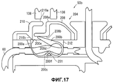
Часть управления первым зажимным приспособлением и часть управления вторым зажимным приспособлением каждая может включать в себя нажимную часть, которая может быть упруго выдвинута вперед или втянута и которая сдавливает первую трубку или вторую трубку с боковой стороны посредством первого зажимного приспособления и второго зажимного приспособления, остроугольный зацепляемый участок, созданный на конце нажимной части, запорную часть, которая может упруго наклоняться, а также участок зацепления, предусмотренный на запорной части, который входит в зацепление с зацепляемым участком нажимной части в состоянии оказания давления на первую трубку или вторую трубку посредством первого зажимного приспособления и второго зажимного приспособления. Это позволяет создать простую конфигурацию части управления первым зажимным приспособлением и части управления вторым зажимным приспособлением.The control part of the first clamping device and the control part of the second clamping device each can include a pressure part that can be elastically extended forward or retracted and which compresses the first tube or second tube from the side by means of the first clamping device and the second clamping device, an acute-angled engaging portion created at the end of the pressure part, the locking part, which can elastically tilt, as well as the engagement section provided on the locking part, which ory engages with the engaging portion of the pressing portion in a state of exerting pressure on a first tube or the second tube by a first clamping device and second clamping device. This allows a simple configuration of the control part of the first clamping device and the control part of the second clamping device.
Когда первое зажимное приспособление и второе зажимное приспособление установлены в кассете параллельно друг другу, можно эффективно использовать поверхность параллельной установки, при этом обеспечивается балансировка.When the first clamping device and the second clamping device are mounted parallel to each other in the cassette, the surface of the parallel installation can be effectively used, while balancing is ensured.
Предпочтительно, чтобы вся кровь или компонент крови, собранные от множества доноров, накапливались в первом мешке, при этом контейнерная система для крови устанавливается в устройстве для центрифугирования и сепарирования с целью центрифугирования жидкости, содержащейся в первом мешке, для разделения на супернатантную жидкость и осадочную жидкость, что приводит к удалению заданного компонента из супернатантной жидкости с помощью фильтра, и переноса (отделения) супернатантной жидкости, лишенной заданного компонента, во второй мешок.Preferably, all blood or a blood component collected from a plurality of donors is accumulated in the first bag, wherein the blood container system is installed in a centrifugation and separation device for centrifuging the liquid contained in the first bag to separate it into the supernatant liquid and sedimentary liquid , which leads to the removal of a given component from the supernatant fluid using a filter, and transfer (separation) of the supernatant fluid devoid of the given component into the second bag.
Может использоваться конфигурация, при которой устройство для центрифугирования и сепарирования включает в себя первый датчик и второй датчик, каждый из которых имеет светоизлучающий участок и светоприемный участок и детектирует вид жидкости, проходящей между светоизлучающим участком и светоприемным участком, при этом кассета имеет отверстие для датчиков, в которое введены первый датчик и второй датчик, причем первая трубка расположена так, чтобы проходить между светоизлучающим участком и светоприемным участком первого датчика, в то время как вторая трубка расположена так, чтобы проходить между светоизлучающим участком и светоприемным участком второго датчика. Это дает возможность с уверенностью распознавать жидкости, присутствующие в первой трубке и второй трубке.A configuration may be used in which the centrifugation and separation device includes a first sensor and a second sensor, each of which has a light emitting portion and a light receiving portion and detects a type of liquid passing between the light emitting portion and the light receiving portion, wherein the cassette has an opening for the sensors, into which the first sensor and the second sensor are inserted, the first tube being arranged so as to pass between the light-emitting section and the light-receiving section of the first sensor, while while the second tube is located so as to pass between the light emitting portion and the light receiving portion of the second sensor. This makes it possible to confidently recognize liquids present in the first tube and the second tube.
Согласно контейнерной системе для крови и кассете, имеющим отношение к настоящему изобретению, первая трубка и вторая трубка заранее установлены должным образом в кассете контейнерной системы для крови, при этом кассету достаточно установить в заданном участке заданного устройства для центрифугирования и сепарирования или схожего устройства. Таким образом, исключается необходимость в сложном укладывании и расположении первой и второй трубок, а также необходимость в расположении первого и второго зажимных приспособлений, за счет чего требуемая установка кассеты может быть выполнена легко и надежно. Кроме того, часть первого зажимного приспособления и часть второго зажимного приспособления созданы в кассете, или первое зажимное приспособление и второе зажимное приспособление удерживаются в кассете, а потому части зажимных приспособлений или зажимные приспособления должным образом расположены относительно средства приведения в действие зажимного приспособления в устройстве для центрифугирования и сепарирования или подобном устройстве.According to the blood container system and the cassette related to the present invention, the first tube and the second tube are pre-installed properly in the cassette of the blood container system, and it is sufficient to install the cassette in a predetermined portion of a predetermined centrifugation and separation device or the like. This eliminates the need for complex laying and arrangement of the first and second tubes, as well as the need for the location of the first and second clamping devices, due to which the required installation of the cartridge can be performed easily and reliably. In addition, part of the first clamping device and part of the second clamping device are created in the cassette, or the first clamping device and the second clamping device are held in the cassette, and therefore parts of the clamping devices or clamping devices are properly located relative to the means for actuating the clamping device in the centrifugation device and separation or the like.
КРАТКОЕ ОПИСАНИЕ ЧЕРТЕЖЕЙBRIEF DESCRIPTION OF THE DRAWINGS
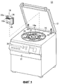
На Фиг.1 показан вид в перспективе устройства для центрифугирования и сепарирования;Figure 1 shows a perspective view of a device for centrifugation and separation;
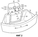
на Фиг.2 показан частичный увеличенный вид в перспективе барабана центрифуги устройства для центрифугирования и сепарирования;figure 2 shows a partial enlarged perspective view of a centrifuge drum of a device for centrifugation and separation;
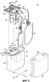
на Фиг.3 показан покомпонентный вид в перспективе вставного блока;figure 3 shows an exploded perspective view of the plug-in unit;
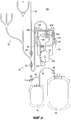
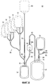
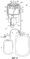
на Фиг.4 показан вид в плане контейнерной системы для крови по первому варианту осуществления настоящего изобретения;4 is a plan view of a blood container system of a first embodiment of the present invention;
на Фиг.5 показан вид в плане составной контейнерной системы;Figure 5 shows a plan view of a composite container system;
на Фиг.6 показан частичный увеличенный вид в плане контейнерной системы для крови по первому варианту осуществления;6 shows a partial enlarged plan view of a blood container system in the first embodiment;
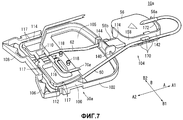
на Фиг.7 показан частичный увеличенный вид в перспективе контейнерной системы для крови по первому варианту осуществления в состоянии, при котором держатель фильтра находится в разложенном состоянии;7 shows a partial enlarged perspective view of the blood container system of the first embodiment in a state in which the filter holder is in the unfolded state;
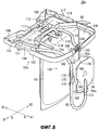
на Фиг.8 показан частичный увеличенный вид в перспективе контейнерной системы для крови по первому варианту осуществления в состоянии, при котором держатель фильтра наклонен на 90°;on Fig shows a partial enlarged perspective view of a container system for blood according to the first variant implementation in a state in which the filter holder is tilted 90 °;
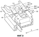
на Фиг.9 показан вид в перспективе в окрестности отверстия для датчиков в кассете;figure 9 shows a perspective view in the vicinity of the holes for the sensors in the cassette;
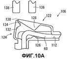
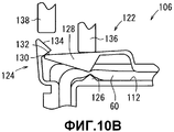
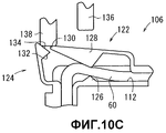
на Фиг.10A показан вид в плане первого зажимного приспособления в начальном состоянии, на фиг.10B показан вид в плане первого зажимного приспособления в замкнутом состоянии, на фиг.10C показан вид в плане первого зажимного приспособления в процессе его возвратного перемещения;Fig. 10A shows a plan view of a first clamping device in an initial state; Fig. 10B shows a plan view of a first clamping device in a closed state; Fig. 10C shows a plan view of a first clamping device during its return movement;
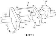
на Фиг.11 показан вид в перспективе шарнирной части и части зацепления трубки в кассете;11 shows a perspective view of the hinge portion and the meshing portion of the tube in the cartridge;
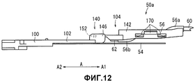
на Фиг.12 показан частичный увеличенный вид сбоку контейнерной системы для крови по первому варианту осуществления в состоянии, при котором держатель фильтра разложен;12 shows a partial enlarged side view of the blood container system of the first embodiment in a state in which the filter holder is unfolded;
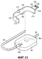
на Фиг.13 показан покомпонентный вид в перспективе фильтра и корпуса держателя;13 shows an exploded perspective view of a filter and a holder body;
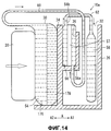
на Фиг.14 схематично проиллюстрированы действия, выполняемые в устройстве для центрифугирования и сепарирования;on Fig schematically illustrates the actions performed in the device for centrifugation and separation;
на Фиг.15 показан частичный увеличенный вид в плане контейнерной системы для крови по второму варианту осуществления изобретения;on Fig shows a partial enlarged view in plan of the container system for blood according to the second variant embodiment of the invention;
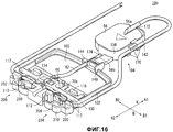
на Фиг.16 показан частичный увеличенный вид в перспективе контейнерной системы для крови по второму варианту осуществления в состоянии, при котором держатель фильтра не наклонен;on Fig shows a partial enlarged perspective view of a container system for blood according to the second variant implementation in a state in which the filter holder is not tilted;
на Фиг.17 показан вид в плане части управления первым зажимным приспособлением;17 is a plan view of a control portion of a first clamping device;
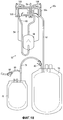
на Фиг.18 показан частичный увеличенный вид в плане контейнерной системы для крови по третьему варианту осуществления изобретения;on Fig shows a partial enlarged view in plan of the container system for blood according to the third variant embodiment of the invention;
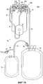
на Фиг.19 показан частичный увеличенный вид в плане контейнерной системы для крови по четвертому варианту осуществления изобретения.on Fig shows a partial enlarged view in plan of the container system for blood according to the fourth variant embodiment of the invention.
ОПИСАНИЕ ВАРИАНТОВ ОСУЩЕСТВЛЕНИЯDESCRIPTION OF EMBODIMENTS
Ниже описываются контейнерная система для крови и соответствующая кассета согласно настоящему изобретению, при этом варианты их осуществления показаны и описаны со ссылкой на прилагаемые фиг.1-19.The following describes a container system for blood and the corresponding cartridge according to the present invention, with options for their implementation are shown and described with reference to the accompanying figures 1-19.
Контейнерные системы 10a, 10b, 10c, 10d для крови и кассеты 50a, 50b, 50c, 50d по вариантам осуществления с первого по четвертый соответственно устанавливаются в устройстве 11 для центрифугирования и сепарирования с целью центрифугирования цельной крови или компонента крови (который в последующих вариантах осуществления будем называть лейкоцитной пленкой), приготовленного из цельной крови, для получения супернатантной жидкости и осадочной жидкости и переноса супернатантной жидкости.
Сначала будет описано устройство 11 для центрифугирования и сепарирования. В последующем описании направление стрелки A на фиг.2 будет принято за радиальное направление, а направление стрелки B будет принято за направление движения по кругу. Собственно говоря, направление движения по кругу - это направление вдоль дуги окружности, как обозначено стрелкой B. Для удобства описания, однако, направление, ортогональное к стрелке A в описываемом месте, также будет называться направлением движения по кругу.First, a
Как показано на фиг.1, устройство 11 для центрифугирования и сепарирования имеет коробчатую форму и включает в себя верхнюю крышку 12, которая может открываться и закрываться, барабан 14 центрифуги (средство центрифугирования) внутри устройства, шесть полостей 16 для введения блоков, расположенных на одинаковом угловом расстоянии друг от друга (60°) в барабане 14 центрифуги, шесть вставных блоков 18, вводимых соответственно в полости 16 для введения блоков, а также шесть прижимных элементов 20 (прижимное средство), предусмотренных в центральной зоне и способных перемещаться вперед и назад в радиальном направлении вращения относительно вставных блоков 18.As shown in figure 1, the
Устройство 11 для центрифугирования и сепарирования управляется на основе операций, выполняемых на консольной секции 22, установленной спереди устройства. Кроме того, устройство 11 для центрифугирования и сепарирования управляется посредством микрокомпьютера (не показан) и может отображать заданную информацию на мониторе 24.The
Как показано на фиг.2, центральная часть 14a центрального барабана 14 имеет удерживающий рычаг 25, являющийся поджимающим упругую часть и удерживающим концевой участок держателя 38 кассеты, электроды 27, первые стержни 136 и вторые стержни 138, а также прижимной элемент 20. Первые стержни 136 и вторые стержни 138 предусмотрены в виде двух пар, при этом среди данных стержней стержни на первой стороне окружного направления B1 образуют средство приведения в действие 17a первого зажимного приспособления для закрытия или открытия первой части зажимного приспособления 106 (см. фиг.3), а стержни на второй стороне окружного направления B2 образуют средство приведения в действие 17b второго зажимного приспособления для закрытия или открытия второй части зажимного приспособления 108 (см. фиг.3). Секция, показанная на фиг.2, может быть выполнена в виде единого блока, при этом шесть таких блоков могут быть объединены друг с другом вдоль направления движения по кругу.As shown in figure 2, the
Как показано на фиг.3, вставной блок 18 имеет корпус 26 блока, корпус 28 кожуха и контейнерную систему 10a для крови. Корпус 26 блока представляет собой имеющий дно футляр, который на виде сверху имеет форму широкой дуги окружности и открыт в своей верхней части, причем малая камера (первая камера) 30 на стороне внутреннего диаметра и большая камера (вторая камера) 32 отделены друг от друга дугообразной стенкой 34. Контейнерный мешок 54 для лейкоцитной пленки (первый мешок), который будет описан позднее, располагается в малой камере 30, в то время как мешок 58 для сбора тромбоцитов (второй мешок) и мешок 76 для сбора проб располагаются в большой камере 32. Мешок 58 для сбора тромбоцитов имеет увеличенную площадь поверхности для обеспечения соответствующей проницаемости кислорода для тромбоцитов, которые в нем содержатся, при этом он больше контейнерного мешка 54 для лейкоцитной пленки.As shown in FIG. 3, the plug-in
Контейнерный мешок 54 для лейкоцитной пленки (BC-контейнерный мешок), мешок 58 для сбора тромбоцитов и мешок 76 для сбора проб образованы, например, с помощью способа, при котором гибкие листовые части, выполненные из гибкого полимера, такого как поливинилхлорид и полиолефин, накладывают друг на друга и участки уплотнения по их периферийным кромкам соединяют оплавлением (тепловым оплавлением, ультразвуковой сваркой) или склеивают, чтобы получить корпус в форме мешка.A white blood cell container bag 54 (BC container bag),
Малая камера 30 открывается не только в верхней части, но также и на стороне внутреннего диаметра. Карман 36 для фильтра, предназначенный для удерживания фильтра 56, и крепление 142, которые будут описаны далее, предусмотрены на стороне наружного диаметра стенки 34. Пластинчатый держатель 38 кассеты, который выступает со стороны внутреннего диаметра, предусмотрен на обоих концевых участках на стороне внутреннего диаметра малой камеры 30.
Держатель 38 кассеты включает в себя первый датчик 40 и второй датчик 42 для распознавания видов жидкостей, поступающих по первой трубке 60 и второй трубке 62, обе будут описаны позднее, а также отсоединительные рычаги 44 и выступы 45 держателя, созданные на обоих концах в направлении движения по окружности. Первый датчик 40 и второй датчик 42 включают в себя светоизлучающие участки 40a, 42a (см. фиг.9), а также светоприемные участки 40b, 42b (см. фиг.9), при этом вид жидкости, проходящей между этими участками, может определяться на основе степени пропускания света через жидкость. Светоизлучающие участки 40a, 42a и светоприемные участки 40b, 42b расположены параллельно друг другу и незначительно выступают вверх на верхней поверхности держателя 38 кассеты. На нижней поверхности держателя 38 кассеты предусмотрено множество контактов (не показаны) для соединения с первым датчиком 40 и вторым датчиком 42 или с их схемами сопряжения. Когда контакты расположены в соприкосновении с электродами 27 получающей стороны (см. фиг.2), предусмотренными на центральной части 14a барабана 14 центрифуги, сигналы с первого датчика 40 и второго датчика 42 могут поступать в микрокомпьютер.The
Корпус 28 кожуха включает в себя кожух, установленный на корпусе 26 блока с его наружной боковой стороны. Корпус 28 кожуха способен закрывать наружную боковую поверхность, верхнюю поверхность и нижнюю поверхность корпуса 26 блока и может надежно удерживать контейнерную систему 10a для крови, установленную в корпусе 26 блока.The
Далее будут описаны контейнерная система 10a для крови и кассета 50a по первому варианту осуществления. Как показано на фиг.4, контейнерная система 10a для крови содержит составной мешок 52 и кассету 50a.Next, a
Как показано на фиг.5, составной мешок 52 включает в себя BC-контейнерный мешок 54, в котором накапливается лейкоцитная пленка (компонент крови) и в котором лейкоцитная пленка подвергается центрифугированию для получения супернатантной жидкости (компонента крови) и осадочной жидкости с помощью барабана 14 центрифуги, фильтр 56 для удаления белых клеток крови (заданных клеток) из супернатантной жидкости, переносимой путем сдавливания BC-контейнерного мешка 54 с помощью прижимного элемента 20, мешок 58 для сбора тромбоцитов для накапливания супернатантной жидкости, полученной после удаления белых клеток крови с помощью фильтра 56, первую трубку 60 для соединения BC-контейнерного мешка 54 с входным отверстием 56a фильтра 56, а также вторую трубку 62 для соединения мешка 58 для сбора тромбоцитов с выходным отверстием 56b фильтра 56. Фильтр 56 предпочтительно снабжен меткой, указывающей направление тока крови.As shown in FIG. 5, the
Фильтр 56 (см. фиг.13) имеет примерно эллипсоподобную форму тонкой пластины, при этом входное отверстие 56a создано на первой боковой поверхности с одного его конца, а выходное отверстие 56b создано на второй боковой поверхности с другого его конца. Входное отверстие 56a и выходное отверстие 56b содержат трубчатый корпус, вытянутый в направлении, совпадающем с продольным направлением фильтра 56. Внутри фильтра 56 предусмотрена планарная фильтрующая среда 57 (см. фиг.14) для разделения внутреннего пространства на первую боковую поверхность и вторую боковую поверхность соответственно.The filter 56 (see FIG. 13) has an approximately ellipse-like shape of a thin plate, with an
Составной мешок 52 дополнительно включает в себя третью трубку 70, имеющую концевой участок, к которому может быть подсоединен контейнер 68 для жидкости, сохраняющей тромбоциты, при этом ее другой конец соединен с BC-контейнерным мешком 54, разветвленную трубку 74, которая имеет разветвления (например, на шесть ветвей, образованных посредством бифуркации и трифуркации) от третьей трубки 70 и к которой может подсоединяться множество BC-мешков 72, мешок 76 для сбора проб, предназначенный для сбора проб жидкости, содержащейся в мешке 58 для сбора тромбоцитов, четвертую трубку 78 для соединения между собой мешка 58 для сбора тромбоцитов и мешка 76 для сбора проб, а также трубку 80 для сбора проб, которая ответвляется от четвертой трубки 78. Когда контейнерная система 10a для крови установлена в устройстве 11 для центрифугирования и сепарирования, третью трубку 70 отсекают после ее оплавления, чтобы предотвратить утечку в местоположении рядом с BC-контейнерным мешком 54. Участок, оставшийся после отсечения, образует третью трубку 70a (см. фиг.7).The
Составной мешок 52 включает в себя зажим 82, предусмотренный в окрестности концевого участка третьей трубки 70, зажим 84, предусмотренный на стороне конца относительно участка разветвления третьей трубки 70, зажим 86, предусмотренный в окрестности концевого участка четвертой трубки 78, а также зажим 88, предусмотренный для трубки 80 для сбора проб. Каждая из трубок в контейнерной системе 10a для крови представляет собой прозрачную гибкую полимерную трубку.The
Зажимы 82, 84, 86, 88 представляют собой стандартные изделия, используемые по настоящее время, при этом трубки, на которых они установлены, могут перекрываться и открываться путем манипулирования зажимами с помощью пальцев рук. Рекомендуется предусмотреть различную цветовую маркировку зажимов 82, 84, 86, 88 в соответствии с их положением и/или назначением. Во время проведения стерилизации и в режиме хранения контейнерной системы 10a для крови каждый из зажимов 82, 84, 86, 88 находится в открытом состоянии, так что внутренние пространства составного мешка 52 пребывают в состоянии взаимного сообщения и равного уровня стерильности.
Каждый из концевых участков третьей трубки 70, разветвленной трубки 74 и трубки 80 для сбора проб закрыт с помощью заданного средства и пребывает в стерильном состоянии, полученном путем проведения заданной стерилизационной обработки (например, путем гамма-облучения) совместно с кассетой 50a.Each of the end sections of the
Заметим, что хотя для удобства изображения на фиг.5 показано, что BC-мешок 72 и контейнер 68 могут соединяться с составным мешком 52 при отсутствии кассеты 50a, на практике BC-мешок 72 и контейнер 68 соединены в условиях присутствия кассеты 50a в контейнерной системе 10a для крови (см. фиг.4), как будет описано позже.Note that although for the convenience of the image, FIG. 5 shows that the
Возвращаясь к фиг.4, контейнерная система 10a для крови включает в себя составной мешок 52 и кассету 50a. Кассета 50a оборудована первой трубкой 60 и второй трубкой 62.Returning to FIG. 4, the
Как показано на фиг.6, 7 и 8, кассета 50a включает в себя пластинчатую часть 100, устанавливаемую на держателе 38 кассеты, дугообразную часть 102 для соединения обоих концевых участков на наружной стороне пластинчатой части 100, а также держатель 104 фильтра, соединенный с центральным участком по внешней стороне диаметра дугообразной части 102. Материалом для кассеты 50a может служить, например, PP (полипропилен), POM (полиоксиметилен) и т.п.As shown in FIGS. 6, 7 and 8, the
Дугообразная часть 102 по форме повторяет верхний конец стенки 34, а пространство, охватываемое наружной концевой поверхностью пластинчатой части 100 и дугообразной частью 102, имеет ту же форму, что и верхний участок поверхности малой камеры 30, что образует полость 105 для мешка, в которую вводится BC-контейнерный мешок 54. Участок по всей длине дугообразной части 102 может быть оборудован угловой конструкцией для усиления прочности. The
Пластинчатая часть 100 включает в себя первую часть зажимного приспособления 106 и вторую часть зажимного приспособления 108, созданные на стороне внутреннего диаметра посредством формования в виде единого целого, отверстие 110 для датчиков, предусмотренное примерно на центральном участке, в которое вводятся первый датчик 40 и второй датчик 42, первый направляющий проход 112 для направления первой трубки 60, второй направляющий проход 114 для направления второй трубки 62, вспомогательную крепежную часть 116 для крепления короткой третьей трубки 70a, а также два болта (удерживающих частей) 118, предусмотренные на наружном концевом участке.The
Два болта 118 имеют соответствующую форму с увеличенными концевыми частями и вводятся в концевые отверстия BC-контейнерного мешка 54, фиксируя тем самым концевые участки BC-контейнерного мешка 54. BC-контейнерный мешок 54 имеет концевой участок, зафиксированный болтами 118, и участок корпуса, вводимый в полость 105 для мешка. Каждый из болтов 118 может иметь концевой участок, расщепленный надвое, так чтобы образовывать узкую щель. Таким образом, во время закрепления BC-контейнерного мешка 54 болты 118 могут вводиться в концевые отверстия посредством уменьшения их диаметра путем сужения щели, а после введения болты 118 могут возвращаться в их исходное состояние, чтобы предотвратить выскальзывание.The two
Вспомогательная крепежная часть 116 образована стенками, слегка соприкасающимися с обеими боковыми поверхностями третьей трубки 70a, и выполнена с возможностью изгиба в направлении своего наружного диаметра после проведения третьей трубки 70a на достаточное расстояние в первом направлении движения по кругу B1 от концевого участка BC-контейнерного мешка 54 стороны внутреннего диаметра. Это обеспечивает положение, при котором на трубке 70a только достаточно короткий концевой участок выступает от пластинчатой части 100 (см. фиг.7 и 8), при этом выступ направлен наружу (а именно в направлении A1 центрифуги), так что третья трубка 70a не подвержена вибрациям или перемещениям в процессе центрифугирования.The
Первый направляющий проход 112 и второй направляющий проход 114 имеют форму канавки, которая образована стенками, расположенными по обеим сторонам по существу по всей длине проходов, и которая открыта с верхней стороны. Первый направляющий проход 112 и второй направляющий проход 114 оборудованы малыми выступами 117, предотвращающими выскальзывание, на их открытых верхних концевых участках.The
Первый направляющий проход 112 продолжается в направлении внутреннего диаметра от концевого участка BC-контейнерного мешка 54, проходит через отверстие 110 для датчика, совершает изгиб в первом направлении движения по кругу B1 в окрестности концевой поверхности внутренней диаметральной стороны внутреннего диаметра, после этого сразу проходит через первую часть зажимного приспособления 106, совершает изгиб в направлении наружного диаметра в окрестности концевого участка в первом направлении движения по кругу B1 и достигает конца наружного диаметра пластинчатой части 100, где первый направляющий проход 112 изгибается внутрь, так чтобы быть направленным на держатель 104 фильтра.The
Второй направляющий проход 114 продолжается в направлении внутреннего диаметра от отверстия 110 для датчика, совершает изгиб во втором направлении движения по окружности B2 в окрестности концевой поверхности стороны внутреннего диаметра, после этого сразу проходит через вторую часть зажимного приспособления 108, совершает изгиб в направлении наружного диаметра в окрестности концевого участка во втором направлении движения по окружности B2 и далее совершает изгиб в направлении боковой стороны со скосом.The
Как показано на фиг.9, в отверстии 110 для датчиков верхние поверхности первой трубки 60 и второй трубки 62 жестко закреплены двумя консолями 120, концы которых слегка загнуты вниз, и соответственно продолжаются в радиальном направлении. Первая трубка 60 и вторая трубка 62 расположены параллельно в направлении движения по окружности, так чтобы обеспечивались зазоры на обеих боковых поверхностях в направлении движения по окружности отверстия 110 для датчиков и еще один зазор обеспечивался между первой трубкой 60 и второй трубкой 62. Когда кассета 50a устанавливается на держателе 38 для кассеты, первый датчик 40 и второй датчик 42 вводятся в зазоры в отверстии 110 для датчиков, при этом первая трубка 60 расположена между светоизлучающим участком 40a и светоприемным участком 40b, а вторая трубка 62 расположена между светоизлучающим участком 42a и светоприемным участком 42b. Светоприемный участок 40b и светоприемный участок 42b выполнены заодно. Первая трубка 60 и вторая трубка 62 удерживаются четырьмя консолями 120, так чтобы оставаться в устойчивом состоянии вне зависимости от ориентации кассеты 50a. Зазор в направлении движения по окружности между двумя консолями 120, противоположными друг другу в направлении движения по окружности, выполнен зауженным до такой степени, чтобы первая трубка 60 и вторая трубка 62 могли проходить через зазор в сжатом состоянии. Как следует из фиг.7 и 9, первая часть зажимного приспособления 106 и вторая часть зажимного приспособления 108 расположены в окрестности отверстия 110 для датчиков и установлены на стороне дальше по ходу от первого датчика 40 и второго датчика 42.As shown in FIG. 9, in the
Как показано на фиг.10A-10C, первая часть зажимного приспособления 106 имеет закрывающую часть (нажимную часть) 122, которая создана в виде части первого направляющего прохода 112 на участке на стороне первого направления движения по окружности B1, внутреннего окружного конца пластинчатой части 100, и которая перекрывает первую трубку 60, запорную часть 124 для удерживания закрывающей части 122 в процессе ее закрытия, а также треугольный выступ 126, созданный на поверхности на противоположной стороне от закрывающей части 122.As shown in FIGS. 10A-10C, the first portion of the
Закрывающая часть 122 имеет выступающий участок (нажимной участок) 128 для сдавливания первой трубки 60 с ее боковой стороны, а также остроугольный зацепляемый участок 130, предусмотренный на конце выступающего участка 128. Участок основания закрывающей части 122 выполнен достаточно малым в диаметре, так что выступающий участок 128 может упруго выдвигаться вперед или втягиваться по существу в радиальном направлении. Запорная часть 124 имеет участок 132 зацепления, предназначенный для зацепления с зацепляемым участком 130 выступающего участка 128 в состоянии сдавливания первой трубки 60, а также наклонную поверхность 134, образованную на ее конце. Направление, перпендикулярное наклонной поверхности 134, ориентировано в направлении скошенной внутренней стороны. Благодаря наличию наклонной поверхности 134 запорная часть 124 имеет форму конуса на виде в плане. Запорная часть 124 имеет достаточно малый диаметр на участке своего основания и может упруго наклоняться.The
Первая часть зажимного приспособления 106, таким образом, имеет простую конфигурацию. Кроме того, первая часть зажимного приспособления 106 выполнена путем формования в виде единого целого с кассетой 50a, так что нет необходимости в создании зажимного приспособления как независимой составной части и можно достичь снижения числа составных частей.The first part of the
Как показано на фиг.10A, в исходном положении первой части зажимного приспособления 106 выступающий участок 128 закрывающей части 122 отделен от первой трубки 60, благодаря чему первая трубка 60 находится в открытом состоянии.As shown in FIG. 10A, in the initial position of the first portion of the
Как показано на фиг.10B, когда первый стержень 136 центральной части 14a выдвинут для нажатия на закрывающую часть 122 с боковой стороны и для смещения закрывающей части 122, выступающий участок 128 сжимает первую трубку 60, взаимодействуя с выступом 126, так чтобы перекрыть первую трубку 60. В этом случае зацепляемый участок 130 входит в зацепление с участком 132 зацепления путем незначительного наклона запорной части 124. После этого поддерживается перекрытое состояние первой трубки 60 выступающим участком 128, даже после того как первый стержень 136 возвращается в свое исходное положение. As shown in FIG. 10B, when the
Как показано на фиг.10C, когда выдвинут второй стержень 138, его концевая поверхность скользит по наклонной поверхности 134 и проталкивает наружу в направлении боковой стороны запорную часть 124, которая наклоняется, благодаря чему участок 132 зацепления расцепляется с зацепляемым участком 130 и зацепленное состояние оказывается разблокированным. Таким образом, когда второй стержень 138 возвращается в свое исходное положение, первая часть зажимного приспособления 106 возвращается в начальное положение, показанное на фиг.10A, и первая трубка 60 снова находится в открытом состоянии.As shown in FIG. 10C, when the
Поскольку вторая часть зажимного приспособления 108 симметрична первой части зажимного приспособления 106, ее подробное описание будет опущено. С помощью второй части зажимного приспособления 108 вторая трубка 62 может перекрываться и открываться. Когда контейнерная система 10a для крови установлена в устройстве 11 для центрифугирования и сепарирования, первая часть зажимного приспособления 106 и вторая часть зажимного приспособления 108 управляются средством приведения в действие 17a первого зажимного приспособления и средством приведения в действие 17b второго зажимного приспособления центральной части 14a (см. фиг.2). Если контейнерная система 10a для крови не смонтирована, первая часть зажимного приспособления 106 и вторая часть зажимного приспособления 108 могут управляться вручную.Since the second part of the
Как показано на фиг.7 и 8, держатель 104 фильтра имеет шарнирную часть 140, крепление 142 и часть 144 зацепления трубки.As shown in FIGS. 7 and 8, the
Как показано на фиг.11, шарнирная часть 140 главным образом образована парой ушек 146, противоположных друг другу в направлении движения по кругу, и вертикальной стенкой (стопором) 148, предусмотренной на концевой стороне основания. Тонкий выступ 150 выступает в направлении наружного диаметра от нижнего конца вертикальной стенки 148. Вертикальная стенка 148 обеспечивает установку фильтра 56 под более точным углом.As shown in FIG. 11, the
Пара ушек 146 на внутренних своих сторонах оборудованы парой круглых осей 152, которые обращены друг к другу над выступом 150, парой малых верхних фиксаторов 154, обеспеченных на верхних концевых участках на стороне наружного диаметра, а также парой малых преодолеваемых выступов 156, обеспеченных на нижних участках. Как ясно из фиг.11, круглые оси 152 образованы осями, которые продолжаются в направлении движения по кругу, благодаря чему фильтр 56 может иметь наклон по отношению к круглым осям 152.A pair of
Как показано на фиг.12, поскольку круглые оси 152 предусмотрены на верхних участках ушек 146, существует возможность перемещения фильтра 56, выходного отверстия 56b и крепления 142 в соответствующее высокое положение в их развернутом состоянии. Кроме того, когда сборочный узел помещают на поверхности стола, эти элементы нагружают BC-контейнерный мешок 54 лишь своим собственным весом, при этом чрезмерное давление на BC-контейнерный мешок 54 не оказывается. As shown in FIG. 12, since
Как показано на фиг.13, крепление 142 имеет опорную пластину 158, которая касается и тем самым служит опорой одной боковой поверхности в продольном направлении, а также верхней половине участка и нижней половине участка держателя 104 фильтра, часть 160 шарнирного поворота, имеющую полукруглую дугообразную форму сечения, которая входит в зацепление с круглыми осями 152, а также консоль 162, соединяющую концевой участок опорной пластины 158 с частью 160 шарнирного поворота. Консоль 162 включает в себя четырехстороннее отверстие 164, в которое плотно вводится выступ 150, а также левую и правую усиливающие пластины 166. As shown in FIG. 13, the
Опорная пластина 158 включает в себя пару удерживающих фильтр выступов 168, обеспеченных на внутренней стороне, так чтобы удерживать обе поверхности фильтра 56, удерживающие трубку выступы 170, предусмотренные на наружной стороне, так чтобы удерживать первую трубку 60 в трех положениях, первый полукруглый участок 172 выреза (первый участок сопряжения), предусмотренный на верхнем концевом участке для встраивания в него входного отверстия 56a, а также второй полукруглый участок 174 выреза (второй участок сопряжения), предусмотренный на нижнем концевом участке основания для встраивания в него выходного отверстия 56b. В наклонном состоянии первый полукруглый участок 172 выреза расположен на стороне наружного диаметра относительно второго полукруглого участка 174 выреза.The
Когда крепление 142 встроено в шарнирную часть 140, часть 160 шарнирного поворота с консолью 162, направленной вниз, садится на круглые оси 152 с боковой стороны, после чего крепление 142 толкается путем приложения к нему некоторого усилия, позволяя при этом консоли 162 перемещаться до верхних фиксаторов 154. Таким образом, крепление 142 может быть легко установлено на своем месте.When the
Заметим, что шарнирная часть 140 не ограничивается конфигурацией осевого типа, выполненной на основе круглых осей 152. Например, может быть также использована конструкция, в которой происходит изгиб тонкой части или упругой части.Note that the
Часть 144 зацепления трубки создана на участке, прилегающем к шарнирной части 140 дугообразной части 102, для удерживания тем самым второй трубки 62 в соответствующем пространственном положении.The
Согласно конструкции держателя 104 фильтра фильтр 56 может прочно удерживаться с помощью крепления 142, а первая трубка 60 и вторая трубка 62 могут должным образом удерживаться с помощью удерживающих трубку выступов 170 и части 144 зацепления трубки.According to the design of the
Кроме того, когда часть 160 шарнирного поворота поддерживается с возможностью поворота на круглых осях 152, крепление 142 и фильтр 56 могут наклоняться, принимая различные положения, в том числе развернутое положение (см. фиг.7), при котором крепление 142 и фильтр 56 параллельны кассете 50a и по существу находятся с ней в одной плоскости, а также наклоненное положение (см. фиг.8), при котором крепление 142 и фильтр 56 наклонены на угол 90° относительно кассеты 50a.In addition, when the articulated
В развернутом (распластанном) состоянии, в котором крепление 142 и фильтр 56 по существу находятся в одной плоскости с кассетой 50a, дальнейший их поворот не допускается верхними фиксаторами 154. Однако, поскольку верхние фиксаторы 154 достаточно малы, крепление 142 и фильтр 56 могут при необходимости быть повернуты за верхние фиксаторы 154 путем приложения к ним должного усилия.In the unfolded (flattened) state, in which the
В положении, при котором крепление 142 и фильтр 56 наклонены на 90° относительно кассеты 50a, боковая поверхность консоли 162 входит в поверхностный контакт с вертикальной стенкой 148, за счет чего достигается требуемое угловое положение. В этом случае выступ 150 вводится в четырехстороннее отверстие 164, благодаря чему повышается устойчивость крепления 142. Помимо этого, когда выполняется операция по наклону крепления 142, оба боковых участка крепления 142 перемещаются по преодолеваемым выступам 156 и при этом ощущается соответствующий щелчок. Таким образом, оператор может распознать, что крепление 142 установлено под должным углом.In the position in which the
Закругленный конец выступа 150 может быть увеличен в диаметре, чтобы создать более выраженное ощущение щелчка при введении выступа 150 в четырехстороннее отверстие 164 и чтобы предотвратить выскальзывание выступа 150.The rounded end of the
Согласно конструкции вышеупомянутого держателя 104 фильтра, во время хранения и транспортировки контейнерной системы 10a для крови и в прочих подобных ситуациях путем расположения крепления 142 и фильтра 56 в развернутом состоянии по существу в плоскости кассеты 50a сборочный узел становится достаточно тонким. Соответственно сборочный узел может быть помещен в виниловый полимерный мешок или подобное изделие совместно (например, в виде уложенных один на другой) с BC-контейнерным мешком 54 и мешком 58 для сбора тромбоцитов. Хотя такое «сложенное в мешок» положение на чертежах не показано, из фиг.4 ясно, что контейнерная система 10a для крови может содержаться в сложенном виде в виниловом полимерном мешке, который чуть больше мешка 58 для сбора тромбоцитов, образующего наибольшую по площади составную часть. According to the design of the
Кроме того, когда лейкоцитные пленки вводятся в BC-контейнерный мешок 54 из требуемого количества BC-мешков 72, то расположение крепления 142 и фильтра 56 в развернутом состоянии по существу в плоскости кассеты 50a, гарантирует что система разложена не без пользы, при этом система может легко свисать с кольцевой стойки (girdle stand).In addition, when white blood cells are introduced into the BC-
С другой стороны, предпочтительно предварительно отрегулировать ориентационное положение фильтра 56 при его использовании. В частности, для того чтобы белые клетки крови могли быть удалены фильтром 56, направление потока установлено так, что компонент крови поступает через входное отверстие 56a, а выводится через выходное отверстие 56b.On the other hand, it is preferable to pre-adjust the orientation of the
Согласно конструкции держателя 104 фильтра, когда контейнерная система 10a для крови установлена в устройстве 11 для центрифугирования и сепарирования, система используется в положении, при котором крепление 42 и фильтр 56 наклонены на 90° относительно кассеты 50a. Кроме того, как показано на фиг.8, фильтр 56 удерживается так, что выходное отверстие 56b находится на проксимальной стороне относительно шарнирной секции 140, в то время как входное отверстие 56а находится на дистальной стороне относительно шарнирной секции 140. Таким образом, фильтр 56 используется в положении, при котором направление потока ориентировано против действия центробежной силы. В результате супернатантная жидкость 176 поступает в фильтр 56 против центробежной силы, благодаря чему скорость потока соответствующим образом подавляется, и белые клетки крови надежно выводятся.According to the design of the
Кроме того, поскольку входное отверстие 56a расположено ниже и на стороне наружного диаметра относительно выходного отверстия 56b, супернатантная жидкость 176, поступившая внутрь через входное отверстие 56a, собирается на нижнем участке внутреннего пространства фильтра 56, на наружной стороне фильтрующей среды 57 (см. фиг.14), размещенной в фильтре 56, и распространяется в полость фильтра 56 вдоль поверхности стороны наружного диаметра под воздействием центробежной силы. Когда пространство на наружной стороне фильтрующей среды 57 заполняется, супернатантная жидкость 176 отфильтровывается при прохождении через фильтрующую среду 57 и выводится через выходное отверстие 56b. Таким образом, супернатантная жидкость 176 фильтруется при эффективном использовании полной поверхности фильтрующей среды 57 внутри фильтра 56. Соответственно белые клетки крови могут быть удалены более надежно.In addition, since the
Кроме того, во время сборки держателя 104 фильтра пространственное расположение фильтра 56 определяется первым полукруглым участком 172 выреза, в который встраивается входное отверстие 56a, и полукруглым участком 174 выреза, в который встраивается выходное отверстие 56b, что может предотвратить неправильную сборку. In addition, during assembly of the
Далее будет описан способ использования контейнерной системы 10a для крови и кассеты 50a по первому варианту осуществления, выполненному вышеуказанным способом.Next, a method for using the
На начальном этапе, как показано на фиг.5, зажим 84 на третьей трубке 70, первая часть зажимного приспособления 106 и вторая часть зажимного приспособления 108 находятся в закрытом состоянии. Требуемое количество BC-мешков 72 соединено с разветвленной трубкой 74, а контейнер 68 для жидкости с тромбоцитами соединен с третьей трубкой 70. Соответственно лейкоцитные пленки (или цельная кровь), собранные от различных доноров, резервируются в BC-мешках 72. Далее лейкоцитные пленки собирают из BC-мешков 72 в BC-контейнерный мешок 54.At the initial stage, as shown in FIG. 5, the
На следующем этапе зажим 82 на третьей трубке 70 находится в закрытом состоянии, а зажим 84 открывается, благодаря чему жидкость, содержащая тромбоциты, переносится в BC-мешки 72, при этом жидкость, содержащая тромбоциты, смешивается с лейкоцитными пленками, остающимися в BC-мешках 72.In the next step, the
Далее зажим 84 закрывают, а зажим 82 открывают, за счет чего лейкоцитные пленки, смешанные с жидкостью, сохраняющей тромбоциты, переносятся в BC-контейнерный мешок 54.Next, the
BC-контейнерный мешок 54 сжимают вручную, благодаря чему воздух, содержащийся в BC-контейнерном мешке 54, переносится в BC-мешки 72.The
Далее третью трубку 70 перерезают после оплавления и герметизации по способу, не допускающему протечки, в некотором месте поблизости от BC-контейнерного мешка 54. Оставшийся участок образует короткую третью трубку 70a, как показано на фиг.7, при этом третья трубка 70a закрепляется во вспомогательной крепежной части 116, так что ее конец ориентирован в направлении центрифугирования. Третья трубка 70a может быть обрезана короче, чем показано на фиг.7.Next, the
После этого, как показано на фиг.8, крепление 142 и фильтр 56 наклоняют на 90° относительно кассеты 50a. Держатель 104 фильтра работает на точное и устойчивое удерживание крепления 142 и фильтра 56 в согнутом на 90° состоянии. Поскольку, как говорилось ранее, входное отверстие 56a расположено ниже и на стороне наружного диаметра относительно выходного отверстия 56b, когда крепление 142 и фильтр 56 наклонены на 90° относительно кассеты 50a, скорость потока подавляется, и полная поверхность фильтрующей среды 57 эффективно используется.After that, as shown in FIG. 8, the
Кроме того, как показано на фиг.3, контейнерная система 10a для крови устанавливается во вставном блоке 18. А именно, кассета 50a устанавливается в держателе 38 кассеты и удерживается выступами 45 держателя, BC-контейнерный мешок 54 вводится в малую камеру 30, фильтр 56 и держатель 104 фильтра вводятся в карман 36 для фильтра, а мешок 58 для сбора тромбоцитов и мешок 76 для сбора проб вводятся в большую камеру 32. Заметим, что поскольку фильтр 56 поддерживается достаточно устойчиво в положении, когда он наклонен на 90° с помощью держателя 104 фильтра, конфигурация, при которой карман 36 для фильтра отсутствует, и при этом фильтр 56 и держатель 104 фильтра находятся в большой камере 32, также может использоваться в зависимости от расчетных условий.In addition, as shown in FIG. 3, the
В данном случае, как показано на фиг.9, первая трубка 60 и вторая трубка 62 должным образом расположены в отверстии 110 для датчиков. Таким образом, первая трубка 60 соответственно зажата между светоизлучающим участком 40a и светоприемным участком 40b первого датчика 40, в то время как вторая трубка 62 соответственно зажата между светоизлучающим участком 42a и светоприемным участком 42b второго датчика 42. Разумеется, первая трубка 60 не располагается в зоне детектирования второго датчика 42, а вторая трубка 62 не располагается в зоне детектирования первого датчика 40.In this case, as shown in FIG. 9, the
Дугообразная часть 102 стабилизирована за счет того, что она установлена на верхней концевой поверхности стенки 34 и опирается на нее, так что крепление 142 и фильтр 56, свисающие с дугообразной части 102, также находятся в устойчивом состоянии.The
Кроме того, BC-контейнерный мешок 54 поддерживается с помощью двух болтов 118, в то время как первая трубка 60, соединенная с BC-контейнерным мешком 54, закрепляется вдоль первого направляющего прохода 112. Таким образом, первая трубка 60 расположена и сориентирована в направлении A2 внутреннего диаметра, если смотреть со стороны BC-контейнерного мешка 54.In addition, the BC-
Далее, как показано на фиг.1, вставной блок 18 с введенной в него контейнерной системой 10a для крови вводится в полость 16 для введения блока в устройстве 11 для центрифугирования и сепарирования. В результате концевой участок кассеты 50a фиксируется удерживающим рычагом 25 (см. фиг.2). Кроме того, контакты первого датчика 40 и второго датчика 42 или их схемы сопряжения входят в соприкосновение с электродами 27 (см. фиг.2).Further, as shown in FIG. 1, the
Хотя обычно в устройство 11 для центрифугирования и сепарирования устанавливают шесть вставных блоков 18, число вставных блоков 18 может составлять пять или менее, при условии, что вставные блоки 18 находятся в равновесии (предпочтительно три или два на одинаковых угловых интервалах).Although typically six plug-in
Когда вставной блок 18 введен в полость 16 для введения блока, первая часть зажимного приспособления 106 и вторая часть зажимного приспособления 108 расположены должным образом в соответствующих положениях, обращенных к средству приведения в действие 17a первого зажимного приспособления и средству приведения в действие 17b второго зажимного приспособления (см. фиг.2) соответственно. Поскольку первая трубка 60 и вторая трубка 62 предварительно должным образом установлены вдоль первого направляющего прохода 112 и второго направляющего прохода 114 по отношению к первой части зажимного приспособления 106 и второй части зажимного приспособления 108, первая часть зажимного приспособления 106 и вторая часть зажимного приспособления 108 могут должным образом закрываться и открываться посредством того, что первая часть зажимного приспособления 106 и вторая часть зажимного приспособления 108 управляются микрокомпьютером.When the
Таким образом, в серии операций, с помощью которых контейнерная система 10a для крови и кассета 50a устанавливаются, каждая из трубок в контейнерной системе 10a для крови предварительно должным образом подсоединена. В частности, с помощью первого направляющего прохода 112 и второго направляющего прохода 114 в кассете 50a первая трубка 60 и вторая трубка 62 должным образом расположены относительно отверстия 110 для датчиков, первой части зажимного приспособления 106 и второй части зажимного приспособления 108. Таким образом, оператору не требуется обладать специальными знаниями или пониманием в отношении операций и процедур для расстановки трубок, благодаря чему оператор может просто и быстро выполнить установку контейнерной системы 10a для крови, при этом вероятность неверной установки равна нулю. Первая трубка 60 и вторая трубка 62 предварительно должным образом располагаются в кассете 50a. На практике, таким образом, оператор сможет установить контейнерную систему 10a для крови в устройство для центрифугирования и сепарирования, не прибегая к инструкциям и т.п.Thus, in a series of operations by which the
Далее крышка 12 устройства 11 для центрифугирования и сепарирования закрывается, после чего выполняются этап центрифугирования и этап сепарирования (этап переноса) путем управления консольной секцией 22.Next, the
В процессе автоматической работы устройства 11 для центрифугирования и сепарирования, прежде всего, вращается барабан 14 центрифуги для выполнения этапа центрифугирования. В этом случае первая часть зажимного приспособления 106 и вторая часть зажимного приспособления 108 предварительно находятся в закрытом состоянии. Однако для повышения безопасности работы, как показано на фиг.10B, первый стержень 136 первоначально выдвинут, так что первая часть зажимного приспособления 106 приведена в плоское состояние с помощью закрывающей секции 122. Вторая часть зажимного приспособления 108 также приводится в плоское состояние тем же способом.In the process of automatic operation of the
Как показано на фиг.14, в ходе этапа центрифугирования к лейкоцитной пленке, зарезервированной в BC-контейнерном мешке 54 в малой камере 30, прикладывается центробежная сила. В результате осадочная жидкость 178, содержащая тяжелые компоненты клеток крови и т.п., перемещается в направлении наружного диаметра, в то время как супернатантная жидкость 176, содержащая легкие тромбоцитные компоненты и т.п., перемещается в направлении внутреннего диаметра, посредством чего жидкости отделяются друг от друга. Супернатантная жидкость 176 содержит белые клетки крови. Осадочная жидкость 178 имеет темно-красный цвет и обладает малой прозрачностью, в то время как супернатантная жидкость 176 образована желтовато-белым прозрачным веществом. As shown in FIG. 14, a centrifugal force is applied to the leukocyte film reserved in the
Устройство 11 для центрифугирования и сепарирования переходит от этапа центрифугирования к этапу сепарирования. В ходе этапа сепарирования при продолжающемся вращении барабана 14 центрифуги второй стержень 138 выдвигается, как было показано на фиг.10C, так чтобы наклонить запорную часть 124 и вывести из состояния зацепления, тем самым возвращая устройство 11 для центрифугирования и сепарирования в исходное положение, показанное на фиг.10A, и приводя первую трубку 60 в открытое состояние. Вторая трубка 62 также приводится в открытое состояние тем же способом.The
Далее, как показано на фиг.14, прижимной элемент 20 смещается в направлении A1 центрифугирования, так чтобы оказать давление на BC-контейнерный мешок 54. Внутренний объем BC-контейнерного мешка 54 уменьшается при его зажатии между прижимным элементом 20 и стенкой 34, тем самым содержащаяся в нем жидкость выводится через первую трубку 60. В данном случае во внутреннем объеме BC-контейнерного мешка 54 осадочная жидкость 178 собрана в направлении наружного диаметра, а супернатантная жидкость 176 собрана в направлении внутреннего диаметра. При этом первая трубка 60 ориентирована в направлении внутреннего диаметра, так что в первую трубку 60 выпускается только супернатантная жидкость 176.Further, as shown in FIG. 14, the pressing
Супернатантная жидкость 176, выпущенная в первую трубку 60, проходит за пределы местонахождения первой части зажимного приспособления 106, которое находится в открытом состоянии, после чего белые клетки крови удаляются из нее фильтром 56. В данном случае, поскольку фильтр 56 установлен так, что входное отверстие 56a расположено ниже и на стороне наружного диаметра относительно выходного отверстия 56b, супернатантная жидкость 176 перетекает в направлении против действия силы тяжести и центробежной силы. Следовательно, скорость потока супернатантной жидкости 176 подавляется, при этом удаление белых клеток крови может быть с уверенностью достигнуто посредством эффективного использования полной поверхности фильтрующей среды 57. Супернатантная жидкость 176, прошедшая через фильтр 56, проходит за пределы местонахождения второй части зажимного приспособления 108, которое находится в открытом состоянии, поступает в мешок 58 для сбора тромбоцитов и резервируется в нем.The
Желательно, чтобы супернатантная жидкость 176 в BC-контейнерном мешке 54 переносилась в мешок 58 для сбора тромбоцитов в максимально полном объеме. При этом, однако, нежелательно, чтобы в мешок 58 для сбора тромбоцитов переносилась осадочная жидкость 178. В этой связи жидкости, проходящие через первую трубку 60 и вторую трубку 62, отслеживаются первым датчиком 40 и вторым датчиком 42, и осуществляется контроль, чтобы предотвратить перенос осадочной жидкости 178 в мешок 58 для сбора тромбоцитов. It is desirable that the
В частности, микрокомпьютер регистрирует сигналы, поступающие в него с первого датчика 40 и второго датчика 42, определяет степень прозрачности жидкостей, проходящих через первую трубку 60 и вторую трубку 62, на основе размерных характеристик сигналов и проводит различие между супернатантной жидкостью 176 и осадочной жидкостью 178 по их соответствующим показателям прозрачности.In particular, the microcomputer registers the signals received from the
Когда BC-контейнерный мешок 54 сдавливается прижимным элементом 20 в ходе этапа сепарирования, супернатантная жидкость 176 выводится в первую трубку 60 в начальный период и датчики могут подтвердить, что по ней протекает супернатантная жидкость 176 в силу прозрачности жидкости. When the BC-
По мере того как прижимной элемент 20 продолжает оказывать давление на BC-контейнерный мешок 54, супернатантная жидкость 176 полностью вытекает из BC-контейнерного мешка 54, после чего на выход поступает осадочная жидкость 178. В результате сначала первый датчик 40 детектирует, что жидкость, протекающая через первую трубку 60, поменялась на осадочную жидкость 178. В этот момент времени этап сепарирования может считаться завершенным. Однако для того чтобы собрать тромбоциты в мешок 58 для сбора тромбоцитов в как можно большем объеме, желательно, чтобы части супернатантной жидкости 176, которые остаются в первой трубке 60 и второй трубке 62, также поступили в мешок 58 для сбора тромбоцитов. С этой точки зрения, после обнаружения осадочной жидкости 178 датчиком 40, оказание давления с помощью прижимного элемента 20 может быть продолжено в течение заданного периода времени.As the pressing
Далее, после того как заданный период времени завершился, когда второй датчик обнаруживает, что жидкость, протекающая через вторую трубку 62, поменялась на осадочную жидкость 178, первые стрежни 136 выдвигаются (см. фиг.10B), чтобы закрыть первую часть зажимного приспособления 106 и вторую часть зажимного приспособления 108, переводя тем самым первую трубку 60 и вторую трубку 62 в закрытое состояние. Далее барабан 14 центрифуги останавливается, после чего этап сепарирования завершается.Further, after the predetermined period of time has ended, when the second sensor detects that the fluid flowing through the
После того как заданный период времени с момента детектирования осадочной жидкости 178 первым датчиком 40 завершается, осадочная жидкость 178 достигает фильтра 56, а части супернатантной жидкости 176, оставшиеся в первой трубке 60 и второй трубке 62, соответственно поступают в мешок 58 для сбора тромбоцитов. Заметим, что до завершения заданного отрезка времени осадочная жидкость 178 в принципе не достигает местоположения второго датчика 42 (а именно местоположения отверстия 110 для датчиков). Однако для того чтобы предотвратить подмешивание осадочной жидкости 178 в мешке 58 для сбора тромбоцитов, она контролируется вторым датчиком 42.After the predetermined period of time from the moment of detection of the
Сразу после того как второй датчик 42 обнаружил перенос осадочной жидкости 178 во вторую трубку 62, первая часть зажимного приспособления 106 и вторая часть зажимного приспособления 108 одновременно переводятся в закрытое состояние, так чтобы предотвратить поступление осадочной жидкости 178 дальше по ходу. Существует незначительное запаздывание по времени до того, как первая часть зажимного приспособления 106 и вторая часть зажимного приспособления 108 полностью закроются после обнаружения осадочной жидкости 178 вторым датчиком 42. В случае второй трубки 62, однако, вторая часть зажимного приспособления 108 расположена на стороне дальше по ходу относительно местоположения отверстия 110 для датчиков, где предусмотрен второй датчик 42. Таким образом, осадочная жидкость 178 не перетекает на сторону дальше по ходу от второй части зажимного приспособления 108. Даже если осадочная жидкость 178 поступит за месторасположение второй части зажимного приспособления 108, осадочная жидкость 178 не достигнет мешка 58 для сбора тромбоцитов, поскольку между местоположением второй части зажимного приспособления 108 и мешком 58 для сбора тромбоцитов имеется некоторое расстояние.Immediately after the
После того как этап сепарирования завершен и барабан 14 центрифуги полностью остановлен указанным способом, открывают крышку 12. Вставные блоки 18 вынимают, задействовав удерживающие рычаги 25, и путем отсоединения корпусов 28 кожухов извлекают контейнерные системы 10a для крови. В данном случае кассету 50a можно легко отсоединить от держателя 38 кассеты, просто задействовав отсоединительный рычаг 44 (см. фиг.3).After the separation step is completed and the
Далее первая трубка 60 в контейнерной системе 10a для крови отсекается после сварки оплавлением в некотором месте поблизости от BC-контейнерного мешка 54, после чего BC-контейнерный мешок 54 служит изделием для крови, содержащим компоненты клеток крови. С другой стороны, когда отсекается вторая трубка 62 после сварки оплавлением в некотором месте поблизости от мешка 58 для сбора тромбоцитов, мешок 58 для сбора тромбоцитов служит изделием для крови, содержащим тромбоциты. Часть продукта крови, содержащегося в мешке 58 для сбора тромбоцитов, может быть перенесена в мешок 76 для сбора проб и послужить объектом заданного исследования и т.п.Next, the
Согласно первому варианту осуществления контейнерной системы 10a для крови и кассеты 50a, как говорилось ранее, кассета 50a имеет первую трубку 60 и вторую трубку 62, которые предварительно уложены в ней должным образом, так что установить кассету 50a в центральной части 14a устройства 11 для центрифугирования и сепарирования достаточно просто. Таким образом, устранена необходимость в сложном укладывании и расположении первой трубки 60 и второй трубки 62, также как и необходимость в расположении в определенном порядке первой части зажимного приспособления 106 и второй части зажимного приспособления 108, при этом установка может выполняться легко и с уверенностью. Кроме того, кассета 50a включает в себя первую часть зажимного приспособления 106 и вторую часть зажимного приспособления 108, которые должным образом размещены относительно средства приведения в действие 17a первого зажимного приспособления и средства приведения в действие 17b второго зажимного приспособления в устройстве 11 для центрифугирования и сепарирования.According to a first embodiment of the
Кроме того, поскольку первая часть зажимного приспособления 106 и вторая часть зажимного приспособления 108 выполнены путем формования заодно с кассетой 50a, первая часть зажимного приспособления 106 и вторая часть зажимного приспособления 108 могут быть легко сконфигурированы, при этом такое формование в виде единого целого позволяет уменьшить число составных частей. Разумеется, оператору не требуется устанавливать первую часть зажимного приспособления 106 и вторую часть зажимного приспособления 108 в кассету 50a, так что требуемая процедура проста и отсутствует риск неправильной установки. In addition, since the first part of the
Кассета 50a фиксируется в устройстве 11 для центрифугирования и сепарирования так, чтобы первая трубка 60 и вторая трубка 62 были частично расположены горизонтально и ориентированы в радиальном направлении и так чтобы компоненты крови внутри трубок перетекали в направлении внутреннего диаметра. В этих частях системы компоненты крови поступают против действия центробежной силы, так что скорости их потоков не могут чрезмерно возрастать.The
Кроме того, первая трубка 60 и вторая трубка 62 пресекают отверстие 110 для датчиков на верхней стороне и в радиальном направлении, при этом располагаясь так, чтобы первый датчик 40 и второй датчик 42 могли детектировать их содержимое. Таким образом, жидкости внутри первой трубки 60 и второй трубки 62 могут надежно распознаваться.In addition, the
Два болта 118, служащие в качестве удерживающей части для кассеты 50a, удерживают концевой участок, где расположена первая трубка 60 первого мешка. В результате первая трубка 60 ориентирована в направлении внутреннего диаметра, при этом супернатантная жидкость 176, собранная в направлении внутреннего диаметра на этапе центрифугирования, может переноситься из первой трубки 60 в ходе этапа сепарирования.Two
Каждая из кассет 50a имеет первую часть зажимного приспособления 106 и вторую часть зажимного приспособления 108, установленные параллельно друг другу в направлении движения по кругу, на стороне, обращенной к центру вращения барабана 14 центрифуги устройства 11 для центрифугирования и сепарирования, за счет чего средство приведения в действие 17a первого зажимного приспособления и средство приведения в действие 17b второго зажимного приспособления могут быть расположены сосредоточенным образом в пределах центральной части 14a в секции вращения. Кроме того, при расположении первой части зажимного приспособления 106 и второй части зажимного приспособления 108 рядом друг с другом в направлении движения по кругу поверхность на стороне центра вращения кассеты 50a используется эффективно, при этом обеспечивается хорошая балансировка. Кроме того, при расположении первой части зажимного приспособления 106 и второй части зажимного приспособления 108 параллельно друг другу в направлении движения по кругу кассета 50a образует одинарный слой, в котором перехлест первой трубки со второй трубкой 62 нигде не происходит, при этом кассета 50a имеет простую конструкцию, так что установку первой трубки 60 и второй трубки 62 на стадии изготовления осуществить легко.Each of the
Поскольку кассета 50a включает в себя крепление 142, с помощью которого фильтр 56 удерживается так, чтобы он мог изменять ориентацию, пространственное расположение фильтра 56 в процессе его хранения и в процессе его использования может соответствующим образом изменяться.Since the
Контейнерная система 10a для крови и кассета 50a представляют собой недорогостоящие конструкции, пригодные для одноразового использования. The
Сборка, упаковка и стерилизационная обработка контейнерной системы 10a для крови выполняются изготовителем в условиях заданного контроля качества. Контейнерная система 10a для крови собирается с помощью автоматизированной установки либо собирается вручную с использованием заданного оборудования для сборки. Кроме того, проводятся предварительные испытания с помощью автоматических тестирующих устройств, благодаря чему можно достичь уверенности в правильности сборки.The assembly, packaging and sterilization treatment of the
Далее будут описаны контейнерная система 10b для крови и кассета 50b по второму варианту осуществления. Компоненты контейнерной системы 10b для крови (а также каждой из систем 10c и 10d) и кассеты 50b (а также каждой из кассет 50c и 50d), аналогичные имеющимся в вышеописанных контейнерной системе 10a для крови и кассете 50a, обозначены теми же ссылочными позициями, которые использовались ранее, а подробное описание таких элементов опущено.Next, the
Контейнерная система 10b для крови включает в себя кассету 50b и составной мешок 52. Составной мешок 52 по существу такой же, как использован в контейнерной системе 10a для крови, за тем исключением, что первая трубка 60 и вторая трубка 62 созданы совместно с первым зажимным приспособлением 200 и вторым зажимным приспособлением 202.The
Как показано на фиг.15 и 16, на месте вышеописанных первой части зажимного приспособления 106 и второй части зажимного приспособления 108 (см. фиг.4) в контейнерной системе 10b для крови имеются первое зажимное приспособление 200 и второе зажимное приспособление 202, а также часть 204 управления первым зажимным приспособлением и часть 206 управления вторым зажимным приспособлением для управления первым зажимным приспособлением 200 и вторым зажимным приспособлением 202 и перевода их в закрытое и открытое состояния.As shown in FIGS. 15 and 16, in place of the above-described first part of the
Первое зажимное приспособление 200 и второе зажимное приспособление 202 составляют средство для перекрытия и открытия промежуточных частей первой трубки 60 и второй трубки 62, также как в случае вышеописанных первой части зажимного приспособления 106 и второй части зажимного приспособления 108.The
Как показано на фиг.17, первое зажимное приспособление 200 представляет собой полимерный корпус, на одном конце которого имеется запорная часть 200a, являющаяся короткой и имеющая загиб назад J-образной формы, а на другом конце имеется закрывающая часть (нажимная часть) 200b, чуть более длинная и имеющая загиб назад U-образной формы. Первое зажимное приспособление 200 на внутренней своей стороне дополнительно оборудовано выступом 200c, а на обоих своих концах - отверстиями, в которые вводится первая трубка 60. Выступ 200c расположен в местоположении с незначительным смещением от центра и имеет в себе отверстие 200f. В исходном состоянии закрывающая часть 200b открыта на соответствующую величину.As shown in FIG. 17, the
Запорная часть 200a, закрывающая часть 200b и выступ 220c соответствуют запорной части 124, закрывающей части 122 и выступу 126, описанным выше (см. фиг.10A). Конкретнее, когда закрывающая часть 200b поджимается в направлении внутренней стороны, первая трубка 60 может перекрываться с помощью выступающего участка 200d на внутренней стороне закрывающей части 200b и выступа 200c, пока закрывающая часть 200b удерживается запорной частью 200a.The locking
Когда наклонная поверхность 200e на конце запорной части 200a проталкивается в направлении боковой стороны (либо если наклонная поверхность 200e подвергается нажиму стержнем или подобным элементом с боковой стороны) и запорная часть 200a тем самым наклоняется в направлении боковой стороны, закрывающая часть 200b высвобождается из состояния зацепления и возвращается в свое начальное положение, открывая тем самым первую трубку 60.When the
Второе зажимное приспособление 202 имеет ту же конструкцию, что и первое зажимное приспособление 200. И для первого зажимного приспособления 200, и для второго зажимного приспособления 202 могут быть использованы те же конструкции, что и в вышеупомянутых зажимах 82, 84, 86, 88.The
Часть 204 управления первым зажимным приспособлением в кассете 50b включает в себя первую нажимную часть 208 для проталкивания закрывающей части 200b под действием первого стержня 136 и вторую нажимную часть 210, которая скользит по наклонной поверхности 200e под действием второго стержня 138, так чтобы наклонить запорную часть 200a в направлении боковой стороны. Первая нажимная часть 208 и вторая нажимная часть 210 имеют утончение в окрестности своих участков концов основания, так чтобы обладать упругостью, при этом первая нажимная часть 208 и вторая нажимная часть 210 могут упруго смещаться по существу в радиальном направлении под действием первого стержня 136 и второго стержня 138. Концевые поверхности, расположенные на стороне внутреннего диаметра первой нажимной части 208 и второй нажимной части 210, выполнены в виде наружных плоских поверхностей 208a и 210a по существу вдоль направления движения по окружности, так что такие концевые поверхности подвергаются устойчивому нажиму первым стержнем 136 и вторым стержнем 138.The
Первая нажимная часть 208 снабжена внутренней плоской поверхностью 208b по существу вдоль направления движения по окружности, так чтобы обладать способностью упругого нажима на участок стороны внутреннего диаметра концевого участка закрывающей части 200b. Вторая нажимная часть 210 снабжена наклонной поверхностью 210b, пригодной для скольжения вдоль наклонной поверхности 200e запорной части 200a.The first
Часть 204 управления первым зажимным приспособлением снабжена полостью 212 для зажимного приспособления, в котором удерживается первое зажимное приспособление 200, оставляя при этом малый зазор. Полость 212 для зажимного приспособления по форме выполнена так, что первое зажимное приспособление 200 не может быть в ней установлено в ошибочно отклоненном положении или с обратной ориентацией. В частности, полость 212 для зажимного приспособления оборудована выступом 201 (колоннообразной частью), который введен в отверстие 200f, за счет чего достигается позиционирование первого зажимного приспособления 200. Поскольку выступ 200c и отверстие 200f расположены в местоположении, незначительно смещенном от центра, не существует возможности установить первое зажимное приспособление 200 с обратной ориентацией. В пределах полости 212 для зажимного приспособления обеспечивается зазор, который позволяет запорной части 200a отклоняться в направлении боковой стороны.The first
Часть 206 управления вторым зажимным приспособлением симметрична по форме части 204 управления первым зажимным приспособлением. Часть 204 управления первым зажимным приспособлением и часть 206 управления вторым зажимным приспособлением могут управляться соответственно средством приведения в действие 17a первого зажимного приспособления и средством приведения в действие 17b второго зажимного приспособления (см. фиг.2), при этом могут управляться вручную, когда контейнерная система 10b для крови не установлена в устройстве 11 для центрифугирования и сепарирования.The
Первый направляющий проход 112 и второй направляющий проход 114 в кассете 50b контейнерной системы 10b для крови короче тех, что имеются в вышеописанной контейнерной системе 10a для крови. Первый направляющий проход 112 и второй направляющий проход 114 выполнены так, чтобы продолжаться через верхние участки отверстия 110 для датчиков, направляя тем самым первую трубку 60 в первом направлении движения по окружности B1, а вторую трубку 62 - во втором направлении движения по окружности B2.The
В контейнерной системе 10b для крови и кассете 50b, выполненных как описано выше, первая трубка 60 и вторая трубка 62 предварительно установлены должным образом, точно так же как в вышеописанной контейнерной системе 10a для крови и кассете 50a. Таким образом, достаточно установить кассету 50b в центральную часть 14a устройства 11 для центрифугирования и сепарирования, при этом устранена необходимость в сложном укладывании и расположении первой трубки 60 и второй трубки 62, так что их установка может выполняться легко и с уверенностью. Кроме того, кассета 50b включает в себя первое зажимное приспособление 200, второе зажимное приспособление 202, часть 204 управления первым зажимным приспособлением и часть 206 управления вторым зажимным приспособлением, при этом такие компоненты должным образом размещены относительно средства приведения в действие 17a первого зажимного приспособления и средства приведения в действие 17b второго зажимного приспособления (см. фиг.2) устройства 11 для центрифугирования и сепарирования.In the
В контейнерной системе 10b для крови и кассете 50b в качестве установленных первого зажимного приспособления 200 и второго зажимного приспособления 202 могут применяться традиционно используемые зажимные приспособления общего назначения, так что оператор сможет легко понять принцип работы зажимного средства в процессе манипулирования им вручную. Кроме того, в случае, когда требуется отсоединить составной мешок 52 от кассеты 50b по какой-то причине, первая трубка 60 и вторая трубка 62 могут оставаться перекрытыми с помощью первого зажимного приспособления 200 и второго зажимного приспособления 202.In the
Как показано на фиг.18, контейнерная система 10c для крови и кассета 50c по третьему варианту осуществления имеют соответствующие конфигурации, полученные путем исключения из состава вышеописанных контейнерной системы 10a для крови и кассеты 50a дугообразной части 102 и держателя 104 фильтра. As shown in FIG. 18, the
Как показано на фиг.19, контейнерная система 10d для крови и кассета 50d по четвертому варианту осуществления имеют соответствующие конфигурации, полученные путем исключения из состава вышеописанных контейнерной системы 10b для крови и кассеты 50b дугообразной части 102 и держателя 104 фильтра.As shown in FIG. 19, the
Отказ от держателя 104 фильтра позволяет упростить конфигурацию кассет 50c, 50d. В этом случае фильтр 56 может поддерживаться в соответствующем положении с помощью кармана 36 для фильтра.The rejection of the
Контейнерные системы 10c, 10d для крови и кассеты 50c, 50d имеют тот же эффект работы, что и описанные выше контейнерная система 10a для крови и кассета 50a.The
Контейнерные системы 10a-10d для крови и кассеты 50a-50d применимы не только в устройстве 11 для центрифугирования и сепарирования, но также и в устройстве для сбора компонентов крови, устройстве для сбора цельной крови, автоматическом сепараторе крови и т.д. Жидкость, резервируемая в BC-контейнерном мешке 54, не ограничивается лейкоцитной пленкой и в нем может резервироваться цельная кровь (содержащаяся жидкость), в зависимости от назначения.
Контейнерная система для крови и кассета согласно настоящему изобретению не ограничиваются вышеописанными вариантами осуществления, при этом само собой разумеется, что могут быть использованы различные конфигурации, не отходя от сущности и смысла изобретения.The blood container system and cassette according to the present invention are not limited to the above described embodiments, it goes without saying that various configurations can be used without departing from the essence and meaning of the invention.
Claims (11)
первый мешок (54) для накапливания цельной крови или компонента крови;
фильтр (56), имеющий фильтрующую среду (57) для удаления заданных клеток из компонента крови, полученного путем центрифугирования жидкости, содержащейся в первом мешке (54);
второй мешок (58) для накапливания компонента крови, полученного после удаления заданных клеток с помощью фильтра (56);
первую трубку (60) для соединения первого мешка (54) с входным отверстием фильтра (56);
вторую трубку (62) для соединения второго мешка (58) с выходным отверстием фильтра (56); а также
кассету (50а, 50с) для удерживания части первой трубки (60) и части второй трубки (62),
при этом кассета (50а, 50с) имеет первую часть зажимного приспособления (106) для перекрытия и открытия первой трубки (60) и вторую часть зажимного приспособления (108) для перекрытия и открытия второй трубки (62), причем первая часть зажимного приспособления (106) и вторая часть зажимного приспособления (108) выполнены заодно целое с кассетой (50а, 50с).1. The container system (10A, 10 s) for blood, containing:
a first bag (54) for storing whole blood or a blood component;
a filter (56) having a filter medium (57) for removing predetermined cells from the blood component obtained by centrifuging the liquid contained in the first bag (54);
a second bag (58) for accumulating a blood component obtained after removal of the target cells using a filter (56);
a first tube (60) for connecting the first bag (54) to the inlet of the filter (56);
a second tube (62) for connecting the second bag (58) to the outlet of the filter (56); as well as
a cartridge (50a, 50c) for holding part of the first tube (60) and part of the second tube (62),
wherein the cartridge (50a, 50c) has a first part of the clamping device (106) for closing and opening the first tube (60) and a second part of the clamping device (108) for closing and opening the second tube (62), the first part of the clamping device (106) ) and the second part of the clamping device (108) are integral with the cartridge (50a, 50c).
выступающий участок (128), который может упруго выдвигаться вперед и втягиваться, и который сдавливает первую трубку (60) или вторую трубку (62) с боковой стороны;
остроугольный зацепляемый участок (130), предусмотренный на конце выступающего участка (128);
запорную часть (124), которая может упруго наклоняться; а также участок (132) зацепления, который предусмотрен на запорной части (124) и который входит в зацепление с зацепляемым участком (130) выступающего участка (128), будучи в состоянии оказания давления на первую трубку (60) или вторую трубку (62).2. The blood container system (10a, 10c) according to claim 1, wherein the first part of the clamping device (106) and the second part of the clamping device (108) each include:
a protruding portion (128) that can elastically extend forward and retract, and which compresses the first tube (60) or the second tube (62) from the side;
an acute-angled engaging portion (130) provided at the end of the protruding portion (128);
the locking part (124), which can elastically tilt; as well as an engagement portion (132) which is provided on the locking portion (124) and which engages with the engagement portion (130) of the protruding portion (128) while being able to exert pressure on the first tube (60) or the second tube (62) .
первый мешок (54) для накапливания цельной крови или компонента крови;
фильтр (56), имеющий фильтрующую среду (57) для удаления заданных клеток из компонента крови, полученного путем центрифугирования жидкости, содержащейся в первом мешке (54);
второй мешок (58) для накапливания компонента крови, полученного после удаления заданных клеток с помощью фильтра (56);
первую трубку (60) для соединения первого мешка (54) с входным отверстием фильтра (56);
вторую трубку (62) для соединения второго мешка (58) с выходным отверстием фильтра (56);
первое зажимное приспособление (200) для перекрытия и открытия первой трубки (60);
второе зажимное приспособление (202) для перекрытия и открытия второй трубки (62); а также
кассету (50b, 50d) для удерживания части первой трубки (60) и части второй трубки (62), первого зажимного приспособления (200) и второго зажимного приспособления (202),
при этом кассета (50b, 50d) имеет часть (204) управления первым зажимным приспособлением для управления первым зажимным приспособлением (200), а также часть (206) управления вторым зажимным приспособлением для управления вторым зажимным приспособлением (202), причем часть (204) управления первым зажимным приспособлением и часть (206) управления вторым зажимным приспособлением выполнены заодно целое с кассетой (50b, 50d).5. A container system (10b, 10d) for blood, containing:
a first bag (54) for storing whole blood or a blood component;
a filter (56) having a filter medium (57) for removing predetermined cells from the blood component obtained by centrifuging the liquid contained in the first bag (54);
a second bag (58) for accumulating a blood component obtained after removal of the target cells using a filter (56);
a first tube (60) for connecting the first bag (54) to the inlet of the filter (56);
a second tube (62) for connecting the second bag (58) to the outlet of the filter (56);
a first fixture (200) for closing and opening the first tube (60);
a second clamping device (202) for closing and opening the second tube (62); as well as
a cartridge (50b, 50d) for holding part of the first tube (60) and part of the second tube (62), the first clamping device (200) and the second clamping device (202),
wherein the cassette (50b, 50d) has a first clamping device control part (204) for controlling the first clamping device (200), and a second clamping device control part (206) for controlling the second clamping device (202), moreover, part (204) the first clamping device and the second clamping part (206) are integral with the cartridge (50b, 50d).
выступающий участок (200d), который может упруго выдвигаться вперед и втягиваться и который сдавливает первую трубку (60) или вторую трубку (62) с боковой стороны посредством первого зажимного приспособления (200) и второго зажимного приспособления (202);
остроугольный зацепляемый участок (130), предусмотренный на конце выступающего участка (200d);
запорную часть (200а), которая может упруго наклоняться; а также
участок (132) зацепления, который предусмотрен на запорной части (200а) и который входит в зацепление с зацепляемым участком (130) выступающего участка (200d), будучи в состоянии оказания давления на первую трубку (60) или вторую трубку (62) посредством первого зажимного приспособления (200) и второго зажимного приспособления (202).6. The blood container system (10b, 10d) according to claim 5, wherein the first clamping device control part (204) and the second clamping device control part (206) each includes:
a protruding portion (200d) that can elastically extend forward and retract and which compresses the first tube (60) or the second tube (62) from the side by means of the first clamping device (200) and the second clamping device (202);
an acute angled engaging portion (130) provided at the end of the protruding portion (200d);
the locking part (200A), which can elastically tilt; as well as
the engagement portion (132) which is provided on the locking portion (200a) and which engages with the engagement portion (130) of the protruding portion (200d) while being able to exert pressure on the first tube (60) or the second tube (62) by means of the first clamping device (200) and a second clamping device (202).
контейнерная система (10b, 10d) для крови выполнена с возможностью установки в устройстве (11) для центрифугирования и сепарирования, с целью центрифугирования жидкости, содержащейся в первом мешке (54) для получения супернатантной жидкости и осадочной жидкости, удаления заданного компонента из супернатантной жидкости с помощью фильтра (56), а также для переноса супернатантной жидкости, лишенной заданного компонента, во второй мешок (58).8. The blood container system (10b, 10d) according to claim 5, in which whole blood or a blood component collected from a plurality of donors can accumulate in the first bag (54), wherein
the container system (10b, 10d) for blood is configured to be installed in a device (11) for centrifugation and separation, with the aim of centrifuging the liquid contained in the first bag (54) to obtain supernatant liquid and sedimentary liquid, removing a given component from the supernatant liquid with using a filter (56), as well as for transferring a supernatant fluid devoid of a given component into a second bag (58).
при этом первая трубка (60) расположена так, чтобы проходить между светоизлучающим участком (40а) и светоприемным участком (40b) первого датчика (40), в то время как вторая трубка (62) расположена так, чтобы проходить между светоизлучающим участком (42а) и светоприемным участком (42b) второго датчика (42).9. The container system (10b, 10d) according to claim 5, in which the cartridge (50a, 50c) has an opening (110) for receiving the first sensor (40) and the second sensor (42) of the device (11) for centrifuging and separating the sensors, moreover, each of the sensors has a light emitting section (40a, 42a) and a light receiving section (40b, 42b) and is configured to detect the type of liquid passing between the light emitting section (40a, 42a) and the light receiving section (40b, 42b),
wherein the first tube (60) is located so as to pass between the light-emitting section (40a) and the light-receiving section (40b) of the first sensor (40), while the second tube (62) is located so as to pass between the light-emitting section (42a) and a light receiving portion (42b) of the second sensor (42).
второй мешок (58) для накопления компонента крови, полученного после удаления заданных клеток с помощью фильтра (56);
первую трубку (60) для соединения первого мешка (54) с входным отверстием фильтра (56);
вторую трубку (62) для соединения второго мешка (58) с выходным отверстием фильтра (56),
при этом кассета (50а, 50с) удерживает часть первой трубки (60) и часть второй трубки (62) и включает в себя первую часть зажимного приспособления (106) для перекрытия и открытия первой трубки (60) и вторую часть зажимного приспособления (108) для перекрытия и открытия второй трубки (62), причем первая часть зажимного приспособления (106) и вторая зажимная секция (108) выполнены за одно целое с кассетой (50а, 50с).10. A cassette (50a, 50c) mounted with a composite bag containing: a first bag (54) for storing whole blood or a blood component; a filter (56) having a filter medium (57) for removing predetermined cells from the blood component obtained by centrifuging the liquid contained in the first bag (54);
a second bag (58) for accumulating a blood component obtained after removal of the target cells with a filter (56);
a first tube (60) for connecting the first bag (54) to the inlet of the filter (56);
a second tube (62) for connecting the second bag (58) to the outlet of the filter (56),
wherein the cartridge (50a, 50c) holds a part of the first tube (60) and a part of the second tube (62) and includes a first part of the clamping device (106) for closing and opening the first tube (60) and a second part of the clamping device (108) for closing and opening the second tube (62), the first part of the clamping device (106) and the second clamping section (108) made in one piece with the cartridge (50A, 50C).
второй мешок (58) для накопления компонента крови, полученного после удаления заданных клеток с помощью фильтра (56);
первую трубку (60) для соединения первого мешка (54) с входным отверстием фильтра (56);
вторую трубку (62) для соединения второго мешка (58) с выходным отверстием фильтра (56);
первое зажимное приспособление (200) для перекрытия и открытия первой трубки (60);
второе зажимное приспособление (202) для перекрытия и открытия второй трубки (62),
при этом кассета (50b, 50d) удерживает часть первой трубки (60), часть второй трубки (62), первое зажимное приспособление (200) и второе зажимное приспособление (202) и включает в себя часть (204) управления первым зажимным приспособлением для управления первым зажимным приспособлением (200), а также часть (206) управления вторым зажимным приспособлением для управления вторым зажимным приспособлением (202), причем часть (204) управления первым зажимным приспособлением и часть управления вторым зажимным приспособлением выполнены за одно целое с кассетой (50b, 50d). 11. A cassette (50b, 50d) mounted with a composite bag containing: a first bag (54) for storing whole blood or a blood component; a filter (56) having a filter medium (57) for removing predetermined cells from the blood component obtained by centrifuging the liquid contained in the first bag (54);
a second bag (58) for accumulating a blood component obtained after removal of the target cells with a filter (56);
a first tube (60) for connecting the first bag (54) to the inlet of the filter (56);
a second tube (62) for connecting the second bag (58) to the outlet of the filter (56);
a first fixture (200) for closing and opening the first tube (60);
a second clamping device (202) for closing and opening the second tube (62),
wherein the cartridge (50b, 50d) holds a part of the first tube (60), a part of the second tube (62), a first clamping device (200) and a second clamping device (202) and includes a part (204) for controlling the first clamping device for controlling the first clamping device (200), as well as the second clamping device control part (206) for controlling the second clamping device (202), the first clamping device control part (204) and the second clamping control part are integral with the cartridge (50b, 50d) .
Applications Claiming Priority (3)
| Application Number | Priority Date | Filing Date | Title |
|---|---|---|---|
| JP2008-305211 | 2008-11-28 | ||
| JP2008305211 | 2008-11-28 | ||
| PCT/JP2009/069894 WO2010061863A1 (en) | 2008-11-28 | 2009-11-18 | Blood bag system and cassette |
Publications (2)
| Publication Number | Publication Date |
|---|---|
| RU2011126336A RU2011126336A (en) | 2013-01-10 |
| RU2500103C2 true RU2500103C2 (en) | 2013-12-10 |
Family
ID=42016967
Family Applications (1)
| Application Number | Title | Priority Date | Filing Date |
|---|---|---|---|
| RU2011126336/14A RU2500103C2 (en) | 2008-11-28 | 2009-11-18 | Container system for blood and cartridge |
Country Status (7)
| Country | Link |
|---|---|
| US (3) | US20110238029A1 (en) |
| EP (2) | EP3189861B1 (en) |
| JP (1) | JP5223006B2 (en) |
| CN (1) | CN102215884B (en) |
| BR (1) | BRPI0921339B8 (en) |
| RU (1) | RU2500103C2 (en) |
| WO (1) | WO2010061863A1 (en) |
Families Citing this family (53)
| Publication number | Priority date | Publication date | Assignee | Title |
|---|---|---|---|---|
| DE102007000310A1 (en) | 2007-06-05 | 2008-12-18 | Andreas Hettich Gmbh & Co. Kg | Insert and centrifuge with insert |
| AU2010245166B2 (en) | 2009-05-06 | 2014-04-17 | Alcon Inc. | Multiple segmented peristaltic pump and cassette |
| AU2010276522B2 (en) | 2009-07-29 | 2016-03-10 | Icu Medical, Inc. | Fluid transfer devices and methods of use |
| US20110137231A1 (en) | 2009-12-08 | 2011-06-09 | Alcon Research, Ltd. | Phacoemulsification Hand Piece With Integrated Aspiration Pump |
| DE102010000752A1 (en) * | 2010-01-08 | 2011-07-14 | Andreas Hettich GmbH & Co. KG, 78532 | Cassette and system part which can be used in cooperation with the cassette in a centrifuge |
| DE102010000753A1 (en) | 2010-01-08 | 2011-07-14 | Andreas Hettich GmbH & Co. KG, 78532 | Cassette and system part which can be used in cooperation with the cassette in a centrifuge |
| DE102010030371A1 (en) * | 2010-06-22 | 2013-08-22 | Terumo Bct, Inc. | Connection method and workstation suitable for carrying out the method |
| DE102010030370A1 (en) * | 2010-06-22 | 2011-12-22 | Terumo Europe N.V. | Cassette, workstation and method for labeling containers containing liquid |
| AU2012324021A1 (en) | 2011-12-22 | 2013-07-11 | Icu Medical, Inc. | Fluid transfer devices and methods of use |
| CN104640523B (en) | 2012-12-11 | 2017-07-04 | 爱尔康研究有限公司 | Phacoemulsification Handpiece with Integrated Suction and Irrigation Pump |
| US9962288B2 (en) | 2013-03-07 | 2018-05-08 | Novartis Ag | Active acoustic streaming in hand piece for occlusion surge mitigation |
| US9452253B2 (en) | 2013-03-13 | 2016-09-27 | Keith Samolyk | CPB system with fluid volume control |
| US20140271358A1 (en) * | 2013-03-13 | 2014-09-18 | Keith Samolyk | CPB Pump System With Double Y Tubing |
| US9327066B2 (en) | 2013-03-13 | 2016-05-03 | Keith Samolyk | CPB system with dual function blood reservoir |
| US9693896B2 (en) | 2013-03-15 | 2017-07-04 | Novartis Ag | Systems and methods for ocular surgery |
| US9126219B2 (en) | 2013-03-15 | 2015-09-08 | Alcon Research, Ltd. | Acoustic streaming fluid ejector |
| US9750638B2 (en) | 2013-03-15 | 2017-09-05 | Novartis Ag | Systems and methods for ocular surgery |
| US9915274B2 (en) | 2013-03-15 | 2018-03-13 | Novartis Ag | Acoustic pumps and systems |
| US9545337B2 (en) | 2013-03-15 | 2017-01-17 | Novartis Ag | Acoustic streaming glaucoma drainage device |
| EP2982393B1 (en) * | 2013-04-05 | 2023-02-15 | Terumo Kabushiki Kaisha | Blood bag system |
| US10138025B2 (en) | 2013-04-05 | 2018-11-27 | Terumo Kabushiki Kaisha | Medical bag handling system and medical bag holding cassette |
| AU2014353184B2 (en) | 2013-11-25 | 2017-08-17 | Icu Medical, Inc. | Methods and system for filling IV bags with therapeutic fluid |
| JP2015104449A (en) | 2013-11-29 | 2015-06-08 | テルモ ビーシーティー、インコーポレーテッド | Blood bag system and tube holder |
| US10159778B2 (en) | 2014-03-24 | 2018-12-25 | Fenwal, Inc. | Biological fluid filters having flexible walls and methods for making such filters |
| US9782707B2 (en) | 2014-03-24 | 2017-10-10 | Fenwal, Inc. | Biological fluid filters having flexible walls and methods for making such filters |
| US9796166B2 (en) | 2014-03-24 | 2017-10-24 | Fenwal, Inc. | Flexible biological fluid filters |
| US10376627B2 (en) | 2014-03-24 | 2019-08-13 | Fenwal, Inc. | Flexible biological fluid filters |
| US9968738B2 (en) | 2014-03-24 | 2018-05-15 | Fenwal, Inc. | Biological fluid filters with molded frame and methods for making such filters |
| EP3175229B1 (en) * | 2014-07-28 | 2023-06-07 | Haemonetics Corporation | System for detecting fluid type |
| EP3252140B1 (en) | 2015-01-30 | 2022-03-02 | Toyo Seikan Group Holdings, Ltd. | Cell culturing method and cell culturing device |
| JP2016140299A (en) * | 2015-01-30 | 2016-08-08 | 東洋製罐グループホールディングス株式会社 | Culture bag fixing block, and method for using culture bag fixing block |
| WO2016134317A1 (en) | 2015-02-20 | 2016-08-25 | Terumo Bct, Inc. | Composite liquid bag system holder |
| WO2017096072A1 (en) | 2015-12-04 | 2017-06-08 | Icu Medical, Inc. | Systems methods and components for transferring medical fluids |
| ES2925940T3 (en) * | 2016-01-21 | 2022-10-20 | Transell Co Ltd | blood component separator |
| USD851745S1 (en) | 2016-07-19 | 2019-06-18 | Icu Medical, Inc. | Medical fluid transfer system |
| EP3487468B1 (en) | 2016-07-25 | 2025-10-01 | ICU Medical, Inc. | Systems and components for trapping air bubbles in medical fluid transfer modules and systems |
| US10772916B2 (en) | 2016-09-16 | 2020-09-15 | Fenwal, Inc. | Systems and methods for deriving and collecting platelet products |
| US11712497B2 (en) | 2016-09-30 | 2023-08-01 | Terumo Kabushiki Kaisha | Blood bag system and blood treatment method |
| CN109982731B (en) | 2016-10-03 | 2022-08-19 | 泰尔茂比司特公司 | Centrifugal fluid separation apparatus |
| CN110035779B (en) | 2016-12-02 | 2022-05-13 | 泰尔茂比司特公司 | Composite fluid separation |
| FR3061436B1 (en) * | 2016-12-29 | 2022-01-21 | Maco Pharma Sa | PROTECTIVE CASE FOR COMPONENTS OF A POCKET SYSTEM |
| CN108733035B (en) * | 2017-04-14 | 2019-12-06 | 京东方科技集团股份有限公司 | guide robot |
| NO343863B1 (en) * | 2017-11-09 | 2019-06-24 | Spinchip Diagnostics As | Centrifuge apparatus |
| WO2020006418A2 (en) * | 2018-06-29 | 2020-01-02 | Terumo Bct, Inc | Composite fluid bag system holder |
| US20200277559A1 (en) * | 2019-02-28 | 2020-09-03 | Thermo Electron Led Gmbh | Expressors and Expressor Systems for Separating Components of a Biological Suspension and Methods of Use |
| WO2020184020A1 (en) * | 2019-03-14 | 2020-09-17 | テルモ株式会社 | Blood bag system |
| EP3993846A1 (en) * | 2019-07-22 | 2022-05-11 | TERUMO Kabushiki Kaisha | Flow path device and biological component bag system |
| WO2021015111A2 (en) * | 2019-07-22 | 2021-01-28 | Terumo Kabushiki Kaisha | Flow path device and biological component bag system |
| US11590057B2 (en) | 2020-04-03 | 2023-02-28 | Icu Medical, Inc. | Systems, methods, and components for transferring medical fluids |
| CN111481762B (en) * | 2020-04-21 | 2022-08-19 | 深圳汉诺医疗创新技术有限公司 | Extracorporeal membrane oxygenation system for lung |
| CN121127283A (en) | 2023-06-16 | 2025-12-12 | 泰尔茂株式会社 | Filtration device |
| EP4721776A1 (en) | 2023-06-16 | 2026-04-08 | Terumo Kabushiki Kaisha | Filter device |
| WO2024257880A1 (en) | 2023-06-16 | 2024-12-19 | テルモ株式会社 | Filter device |
Citations (6)
| Publication number | Priority date | Publication date | Assignee | Title |
|---|---|---|---|---|
| US6348156B1 (en) * | 1999-09-03 | 2002-02-19 | Baxter International Inc. | Blood processing systems and methods with sensors to detect contamination due to presence of cellular components or dilution due to presence of plasma |
| RU2001133017A (en) * | 1999-06-10 | 2004-01-27 | Провэлиз Дайагностикс Лимитед (Gb) | Mixing device and method of mixing |
| US6730055B2 (en) * | 2000-03-09 | 2004-05-04 | Gambro Inc. | Extracorporeal blood processing methods and apparatus |
| EP0952858B1 (en) * | 1996-11-22 | 2005-01-12 | Therakos, Inc. | Integrated cassette for valving, pumping and controlling movement of fluids |
| EP1674120A1 (en) * | 2004-12-21 | 2006-06-28 | Therakos, Inc. | Method and apparatus for collecting a blood component and performing a photopheresis treatment |
| CA2688262A1 (en) * | 2007-06-05 | 2008-12-11 | Terumo Europe N.V. | Cartridge and centrifuge having a cartridge |
Family Cites Families (39)
| Publication number | Priority date | Publication date | Assignee | Title |
|---|---|---|---|---|
| JPS5641250B2 (en) * | 1973-08-28 | 1981-09-26 | ||
| DK219881A (en) * | 1980-05-20 | 1981-11-21 | Haemonetics Corp | DEVICE FOR COLLECTION AND COLLECTION OF A LIQUID ISAER FOR USE BY TRANSFUSION OF OWN BLOOD |
| US4322298A (en) * | 1981-06-01 | 1982-03-30 | Advanced Blood Component Technology, Inc. | Centrifugal cell separator, and method of use thereof |
| US4402680A (en) * | 1981-07-09 | 1983-09-06 | Haemonetics Corporation | Apparatus and method for separating fluid into components thereof |
| JPS59182341U (en) * | 1983-05-20 | 1984-12-05 | 泉工医科工業株式会社 | Plasma separation and collection device |
| US5092996A (en) * | 1991-02-19 | 1992-03-03 | Miles Inc. | Blood filtering system |
| GR930100237A (en) * | 1992-06-10 | 1994-02-28 | Pall Corp | System for treating transition zone material. |
| JPH06254153A (en) * | 1993-03-09 | 1994-09-13 | Asahi Medical Co Ltd | Separation of blood component |
| US5482440A (en) * | 1993-12-22 | 1996-01-09 | Baxter Int | Blood processing systems using a peristaltic pump module with valve and sensing station for operating a peristaltic pump tube cassette |
| US5836934A (en) * | 1995-06-07 | 1998-11-17 | Baxter International Inc. | Closed system and methods for mixing additive solutions while removing undesired matter from blood cells |
| JPH09168585A (en) * | 1995-12-18 | 1997-06-30 | Nissho Corp | Blood bag system |
| JP2000515778A (en) * | 1996-07-08 | 2000-11-28 | アニマス コーポレーシヨン | Implantable sensors and systems for in vivo measurement and control of body fluid component levels |
| US7435231B2 (en) * | 1999-07-29 | 2008-10-14 | Fenwal, Inc. | Biological sample device receiver |
| SE0000866L (en) * | 2000-03-16 | 2001-09-17 | Peter Unger Med P U Med Konsul | Method and apparatus for the treatment of biological material |
| US6605223B2 (en) * | 2000-06-20 | 2003-08-12 | Medicept, Inc. | Blood component preparation (BCP) device and method of use thereof |
| US6387030B1 (en) * | 2000-06-30 | 2002-05-14 | Beckman Coulter, Inc. | Internal adapter with a pellet well for a centrifuge container |
| WO2002024303A1 (en) * | 2000-09-20 | 2002-03-28 | Kendro Laboratory Products, L.P. | Blood centrifuge cup having a replaceable compartment for filter support |
| DE10065283A1 (en) * | 2000-12-29 | 2002-07-04 | Hettich Andreas Gmbh & Co Kg | Centrifuge with blood bag system with upper and lower outlet |
| US6866826B2 (en) * | 2000-12-30 | 2005-03-15 | Beckman Coulter, Inc. | Large mouth centrifuge labware |
| US6742760B2 (en) * | 2001-09-27 | 2004-06-01 | Baxter International Inc. | Flow control device |
| DE50208662D1 (en) * | 2001-11-15 | 2006-12-21 | Arcomed Ag | infusion pump |
| US7264608B2 (en) * | 2001-12-05 | 2007-09-04 | Fenwal, Inc. | Manual processing systems and methods for providing blood components conditioned for pathogen inactivation |
| WO2003063930A1 (en) * | 2002-02-01 | 2003-08-07 | Gambro, Inc. | Whole blood collection and processing method |
| US7279107B2 (en) * | 2002-04-16 | 2007-10-09 | Gambro, Inc. | Blood component processing system, apparatus, and method |
| US7601268B2 (en) * | 2003-05-27 | 2009-10-13 | Haemonetics Corporation | Continuous blood filtration and method of use |
| US20050049539A1 (en) | 2003-09-03 | 2005-03-03 | O'hara Gerald P. | Control system for driving fluids through an extracorporeal blood circuit |
| US6870060B1 (en) * | 2003-10-22 | 2005-03-22 | Arco Chemical Technology, L.P. | Product recovery from supercritical mixtures |
| CN1634615A (en) * | 2003-12-31 | 2005-07-06 | 杨星 | leukocyte filter |
| US7234677B2 (en) * | 2004-10-18 | 2007-06-26 | Z-Man Corporation | Pinch clamp |
| JP2006158738A (en) * | 2004-12-08 | 2006-06-22 | Asahi Kasei Medical Co Ltd | Centrifugal method of leukoreduction system |
| US7442178B2 (en) * | 2005-03-09 | 2008-10-28 | Jacques Chammas | Automated system and method for blood components separation and processing |
| US7694828B2 (en) * | 2005-04-27 | 2010-04-13 | Biomet Manufacturing Corp. | Method and apparatus for producing autologous clotting components |
| JP4848143B2 (en) | 2005-06-17 | 2011-12-28 | テルモ株式会社 | Blood component collection device |
| WO2007001739A1 (en) * | 2005-06-22 | 2007-01-04 | Gambro Bct, Inc. | Apparatus and method for separating discrete volumes of a composite liquid |
| JP4827649B2 (en) * | 2005-08-12 | 2011-11-30 | ダイワボウホールディングス株式会社 | Joint forming method for base fabric and slider for forming joint |
| NL2000116C2 (en) * | 2006-06-29 | 2008-01-02 | Klip Consultancy B V | Device comprising a container system for a body fluid. |
| CN102274803B (en) * | 2006-09-06 | 2014-01-01 | 泰尔茂比司特公司 | Apparatus and method for separating a composite liquid into at least two components |
| DE102007000310A1 (en) * | 2007-06-05 | 2008-12-18 | Andreas Hettich Gmbh & Co. Kg | Insert and centrifuge with insert |
| US20090049662A1 (en) * | 2007-08-22 | 2009-02-26 | Miller Stephen C | Clamp Safety Lock with Printable Area |
-
2009
- 2009-11-18 RU RU2011126336/14A patent/RU2500103C2/en active
- 2009-11-18 CN CN200980145435.2A patent/CN102215884B/en not_active Expired - Fee Related
- 2009-11-18 JP JP2011522326A patent/JP5223006B2/en active Active
- 2009-11-18 EP EP17157528.5A patent/EP3189861B1/en active Active
- 2009-11-18 US US13/131,054 patent/US20110238029A1/en not_active Abandoned
- 2009-11-18 EP EP09764912.3A patent/EP2349377B1/en not_active Not-in-force
- 2009-11-18 WO PCT/JP2009/069894 patent/WO2010061863A1/en not_active Ceased
- 2009-11-18 BR BRPI0921339A patent/BRPI0921339B8/en not_active IP Right Cessation
-
2015
- 2015-04-06 US US14/679,693 patent/US9839730B2/en active Active
- 2015-04-06 US US14/679,636 patent/US9839729B2/en active Active
Patent Citations (6)
| Publication number | Priority date | Publication date | Assignee | Title |
|---|---|---|---|---|
| EP0952858B1 (en) * | 1996-11-22 | 2005-01-12 | Therakos, Inc. | Integrated cassette for valving, pumping and controlling movement of fluids |
| RU2001133017A (en) * | 1999-06-10 | 2004-01-27 | Провэлиз Дайагностикс Лимитед (Gb) | Mixing device and method of mixing |
| US6348156B1 (en) * | 1999-09-03 | 2002-02-19 | Baxter International Inc. | Blood processing systems and methods with sensors to detect contamination due to presence of cellular components or dilution due to presence of plasma |
| US6730055B2 (en) * | 2000-03-09 | 2004-05-04 | Gambro Inc. | Extracorporeal blood processing methods and apparatus |
| EP1674120A1 (en) * | 2004-12-21 | 2006-06-28 | Therakos, Inc. | Method and apparatus for collecting a blood component and performing a photopheresis treatment |
| CA2688262A1 (en) * | 2007-06-05 | 2008-12-11 | Terumo Europe N.V. | Cartridge and centrifuge having a cartridge |
Also Published As
| Publication number | Publication date |
|---|---|
| CN102215884B (en) | 2016-01-06 |
| JP5223006B2 (en) | 2013-06-26 |
| JP2012510298A (en) | 2012-05-10 |
| US9839729B2 (en) | 2017-12-12 |
| US20150209496A1 (en) | 2015-07-30 |
| US20150209495A1 (en) | 2015-07-30 |
| EP2349377A1 (en) | 2011-08-03 |
| CN102215884A (en) | 2011-10-12 |
| BRPI0921339A2 (en) | 2016-07-26 |
| BRPI0921339B8 (en) | 2021-06-22 |
| RU2011126336A (en) | 2013-01-10 |
| EP3189861A1 (en) | 2017-07-12 |
| US20110238029A1 (en) | 2011-09-29 |
| US9839730B2 (en) | 2017-12-12 |
| EP3189861B1 (en) | 2025-06-04 |
| BRPI0921339B1 (en) | 2020-02-11 |
| WO2010061863A1 (en) | 2010-06-03 |
| EP2349377B1 (en) | 2017-04-05 |
Similar Documents
| Publication | Publication Date | Title |
|---|---|---|
| RU2500103C2 (en) | Container system for blood and cartridge | |
| RU2486922C2 (en) | Blood container system and cassette | |
| US10286204B2 (en) | Clamp and blood bag system | |
| JP5801301B2 (en) | Clamp and blood bag system | |
| JP5695574B2 (en) | Blood bag system and blood processing method | |
| CN105120912B (en) | Blood bag system |