RU2494807C2 - Method and device for fine material processing in spouted bed - Google Patents
Method and device for fine material processing in spouted bed Download PDFInfo
- Publication number
- RU2494807C2 RU2494807C2 RU2011108940/05A RU2011108940A RU2494807C2 RU 2494807 C2 RU2494807 C2 RU 2494807C2 RU 2011108940/05 A RU2011108940/05 A RU 2011108940/05A RU 2011108940 A RU2011108940 A RU 2011108940A RU 2494807 C2 RU2494807 C2 RU 2494807C2
- Authority
- RU
- Russia
- Prior art keywords
- process chamber
- annular
- chamber
- fluidizing agent
- contour
- Prior art date
Links
Images
Classifications
-
- B—PERFORMING OPERATIONS; TRANSPORTING
- B01—PHYSICAL OR CHEMICAL PROCESSES OR APPARATUS IN GENERAL
- B01J—CHEMICAL OR PHYSICAL PROCESSES, e.g. CATALYSIS OR COLLOID CHEMISTRY; THEIR RELEVANT APPARATUS
- B01J2/00—Processes or devices for granulating materials, e.g. fertilisers in general; Rendering particulate materials free flowing in general, e.g. making them hydrophobic
- B01J2/16—Processes or devices for granulating materials, e.g. fertilisers in general; Rendering particulate materials free flowing in general, e.g. making them hydrophobic by suspending the powder material in a gas, e.g. in fluidised beds or as a falling curtain
Abstract
Description
Настоящее изобретение относится к способу обработки мелкозернистого материала в фонтанирующем слое с признаками, указанными в ограничительной части пункта 1 формулы изобретения, а также к соответствующему устройству, признаки которого приведены в ограничительной части пункта 8 формулы изобретения.The present invention relates to a method for processing fine-grained material in a flowing layer with the characteristics indicated in the restrictive part of
Из патента Германии DE 10322062 A1 известны способ и устройство для нанесения жидкостей на поток твердого вещества в аппарате с фонтанирующим слоем. Подобные аппараты с фонтанирующим слоем отличаются, в частности, тем, что они снабжены прямоугольным реакционным пространством и устройством для подачи газа, неизбежно упорядоченным в направлении оси реакционного пространства, в одинарном или сдвоенном конструктивном исполнении. В случае нескольких реакционных пространств они соединяются между собой посредством устройства для перепуска материала. В случае впрыскивания жидкостей необходимые для этого форсунки располагаются по центру аппарата с фонтанирующим слоем. Устройство для подачи газа выполнено с возможностью регулирования расхода и скорости потока технологического воздуха. Указанный способ и соответствующие устройства отличаются линейной ориентацией направления подачи газа.German patent DE 10322062 A1 discloses a method and apparatus for applying liquids to a solid stream in a gushing layer apparatus. Such devices with a gushing layer are distinguished, in particular, in that they are equipped with a rectangular reaction space and a gas supply device, inevitably ordered in the direction of the axis of the reaction space, in a single or double design. In the case of several reaction spaces, they are interconnected by means of a material transfer device. In case of liquid injection, the nozzles necessary for this are located in the center of the apparatus with a gushing layer. The gas supply device is configured to control the flow rate and flow rate of the process air. The specified method and corresponding devices differ in the linear orientation of the gas supply direction.
Недостаток указанного способа и указанных устройств состоит в том, что для обеспечения равномерной подачи газа по всей протяженности аппарата к точности изготовления устройства для подачи газа предъявляют повышенные требования. Кроме того, длина указанного устройства ограничена, что вынуждает прибегать к мерам, направленным на изменение направления потока материала посредством системы его перепуска. Увеличение длины обусловливает увеличение размеров установки, что приводит к ее удорожанию.The disadvantage of this method and these devices is that in order to ensure uniform gas supply over the entire length of the apparatus, increased demands are made on the accuracy of manufacturing a gas supply device. In addition, the length of the specified device is limited, which forces to resort to measures aimed at changing the direction of the flow of material through its bypass system. The increase in length leads to an increase in the size of the installation, which leads to its appreciation.
Из патента Германии DE 3117892 A1 известен предназначенный для изготовления гранулированных материалов аппарат с фонтанирующим слоем, причем жидкость вводят в пропускаемый через указанный гранулятор поток твердого вещества. Гранулирующий аппарат с фонтанирующим слоем обладает круглым поперечным сечением с конически сужающейся нижней частью. К центральной конической части гранулятора присоединен газовый канал, в котором расположена форсунка для впрыскивания жидкости. С целью поддержания постоянного режима фонтанирования через газовый канал пропускают соответствующий газ. Поступающий в центр газ разрывает вводимую посредством форсунки жидкость и часть находящегося в грануляторе материала, причем возникает канал фонтанирования, в котором жидкость смачивает частицы материала. Орошенный жидкостью материал через конусообразное днище возвращается в канал фонтанирования, то есть происходит циркуляция частиц материала. После достижения соответствующего размера гранулы выгружают из указанного гранулятора с фонтанирующим слоем.From Germany patent DE 3117892 A1, an apparatus with a flowing layer is known intended for the manufacture of granular materials, the liquid being introduced into a solid stream passing through said granulator. The granulating apparatus with a gushing layer has a round cross section with a conically tapering lower part. A gas channel is attached to the central conical part of the granulator, in which a nozzle for injecting liquid is located. In order to maintain a constant flowing mode, the corresponding gas is passed through a gas channel. The gas entering the center breaks the liquid introduced by the nozzle and part of the material in the granulator, and a flowing channel appears in which the liquid wets the particles of material. The material sprinkled with liquid through a conical bottom returns to the flowing channel, that is, particles of the material circulate. After reaching the appropriate size, the granules are discharged from the specified granulator with a gushing layer.
Недостатком аппаратов указанного выше типа с фонтанирующим слоем является проблематичность обеспечения в них равномерного смачивания частиц материала жидкостью, а также создания и поддержания постоянного режима фонтанирования в случае установок с высокой производительностью.A disadvantage of the apparatuses of the type indicated above with a gushing layer is the difficulty of ensuring that they uniformly wet the particles of the material with liquid, as well as creating and maintaining a constant gushing regime in the case of high-performance plants.
К уровню техники относится также использование техники псевдоожиженного слоя в аппаратах с круглой конфигурацией днища, а также общего оборудования, предназначенного для сушки, распылительного гранулирования, агломерации или нанесения покрытий, причем соответствующие технологические процессы можно осуществлять как в периодическом, так и в непрерывном режиме.The prior art also refers to the use of fluidized bed technology in apparatus with a circular bottom configuration, as well as general equipment for drying, spray granulation, agglomeration or coating, and the corresponding technological processes can be carried out both in batch and continuous mode.
В основу настоящего изобретения была положена задача создать способ обработки мелкозернистого материала в фонтанирующем слое, а также пригодное для осуществления указанного способа устройство с возможностью регулирования варьируемых режимов в технологической камере, обладающее простой и экономичной конструкцией, что позволило бы устранить указанные выше недостатки уровня техники.The present invention was based on the task of creating a method for processing fine-grained material in a gushing layer, as well as a device suitable for implementing this method with the ability to control variable modes in the process chamber, which has a simple and economical design, which would eliminate the above-mentioned disadvantages of the prior art.
Указанная задача согласно изобретению решается благодаря способу, отличительные признаки которого приведены в пункте 1 формулы изобретения, и устройству с представленными в пункте 8 отличительными признаками.The specified task according to the invention is solved thanks to the method, the distinguishing features of which are given in
Благодаря тому что в круглый аппарат с фонтанирующим слоем через два регулируемых по ширине кольцевых зазора, находящихся на определенном расстоянии друг от друга, подают ожижающий агент в виде газового потока, причем посредством наружного кольцевого зазора создают круговой газовый поток, конусообразно расширяющийся в направлении наружной стороны технологической камеры, в то время как посредством внутреннего кольцевого зазора создают круговой газовый поток, конусообразно расширяющийся в направлении осевой линии технологической камеры, обеспечивают типичное для фонтанирующих слоев перемещение подлежащего обработке в технологической камере материала. При этом предлагаемое в изобретении устройство включает расположенный по центру нижней части технологической камеры, вдвигаемый внутрь нее вытесняющий элемент, на определенном расстоянии вокруг которого находится кольцеобразный средний контур. Вследствие сочетания вытесняющего элемента с кольцеобразным средним контуром и внутренней кромкой технологической камеры образуются внутренний кольцевой зазор и внешний кольцевой зазор, через которые в технологическую камеру подают используемый в качестве ожижающего агента газовый поток. При этом устройство для подачи газа выполнено с возможностью корректировки параметров газового потока, что позволяет варьировать расход ожижающего агента или соответственно его скорость. Это достигается благодаря расположению перемещающего устройства ниже вытесняющего элемента и кольцеобразного среднего контура.Due to the fact that a fluidizing agent in the form of a gas stream is fed into a round apparatus with a gushing layer through two annular width-adjustable spacers located at a certain distance from each other, and through the outer annular gap a circular gas flow is created, conically expanding towards the outside of the process chambers, while by means of an internal annular gap create a circular gas flow conically expanding in the direction of the axial line of the process chamber The steps provide a typical flowing layer movement of the material to be processed in the process chamber. Moreover, the device proposed in the invention includes a centrally located lower part of the technological chamber, a displacing element pushed inside it, at a certain distance around which there is an annular middle contour. Due to the combination of the displacing element with an annular middle contour and the inner edge of the process chamber, an internal annular gap and an external annular gap are formed, through which a gas stream is used as a fluidizing agent. In this case, the gas supply device is configured to adjust the parameters of the gas stream, which allows you to vary the flow of the fluidizing agent or, accordingly, its speed. This is achieved due to the location of the moving device below the displacing element and the annular middle contour.
Преимуществом предлагаемого в изобретении способа является простота и надежность осуществления соответствующего технологического процесса в сочетании с возможностью регулирования необходимого технологического режима обработки материала. Преимуществом предлагаемого в изобретении устройства является его конструктивная простота, а также простота изготовления используемых в нем деталей, в основном обладающих вращательно-симметричной конфигурацией. Благодаря круглой форме аппарата с фонтанирующим слоем для его монтажа не нужна большая производственная площадь. Вследствие этого уменьшается также масса аппарата.The advantage of the method proposed in the invention is the simplicity and reliability of the implementation of the corresponding technological process in combination with the ability to control the necessary technological regime of material processing. An advantage of the device proposed in the invention is its structural simplicity, as well as the simplicity of manufacturing the parts used in it, mainly having a rotationally symmetrical configuration. Due to the round shape of the apparatus with a gushing layer, a large production area is not needed for its installation. As a result of this, the mass of the apparatus is also reduced.
Другие предпочтительные варианты конструктивного исполнения предлагаемого в изобретении устройства приведены в зависимых пунктах формулы изобретения и более подробно описаны ниже при рассмотрении принципа его действия.Other preferred embodiments of the device proposed in the invention are given in the dependent claims and are described in more detail below when considering the principle of its operation.
Ниже изобретение более подробно рассмотрено на примере некоторых вариантов его осуществления со ссылкой на прилагаемые к описанию чертежи, на которых показано:Below the invention is described in more detail on the example of some variants of its implementation with reference to the accompanying drawings, which show:
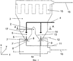
на фиг.1 сечение через предлагаемый в изобретении аппарат с фонтанирующим слоем иfigure 1 section through the proposed in the invention apparatus with a gushing layer and
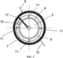
на фиг.2 разрез показанного на фиг.1 аппарата плоскостью по A-A.in Fig.2 a section shown in Fig.1 of the apparatus by a plane along A-A.
Показанный на фиг.1 аппарат с фонтанирующим слоем обладает круглой формой и включает технологическую камеру 5 с цилиндрической верхней частью и конической нижней частью. Выше технологической камеры 5 находится конически расширяющаяся расширительная камера 3. Ниже технологической камеры 5 расположена приточная камера 1, предназначенная для подачи ожижающего агента в технологическую камеру 5. Позицией 10 обозначен вход ожижающего агента в приточную камеру 1. Ожижающим агентом, как правило является газовый поток, который в соответствии с подлежащей осуществлению обработкой материала термостатируют в технологической камере 5.The apparatus with a gushing layer shown in FIG. 1 has a round shape and includes a
Технологическая камера 5 снизу ограничена расположенным в центре вытесняющим элементом 2 и находящимся на определенном расстоянии от него кольцеобразным средним контуром 9. При этом вытесняющий элемент 2, который обладает вращательно-симметричной конфигурацией, а также средний контур 9 выполнены таким образом, что их профиль вдается внутрь технологической камеры 5. Вытесняющий элемент 2 имеет выступающую в направлении технологической камеры 5 и конически сужающуюся вдоль оси X часть, к которой может примыкать цилиндрическая часть. Вследствие наличия в технологической камере 5 вытесняющего элемента 2 она обладает кольцеобразной поверхностью основания. Технологическая камера 5 расширяется в направлении от кольцеобразной поверхности основания вдоль оси X, причем ее расширение с одной стороны ограничено расширяющимся во внешнюю сторону коническим внешним контуром 14, а с другой стороны расширяющимся внутрь контуром 13 вытесняющего элемента 2.The
Средний контур 9 выполнен таким образом, что его внешний периметр ниже внешнего края технологической камеры 5 образует зазор 7', в то время как его внутренний периметр ниже внешнего края вытесняющего элемента 2 образует зазор 8'. При этом, как показано на фиг.1, соответствующие зазоры расширяются в направлении оси X. Ниже вытесняющего элемента 2 и среднего контура 9 находится не показанное на чертежах перемещающее устройство, которое предназначено для регулирования соответствующей ширины зазора 7' и/или 8'.The
Вытесняющий элемент 2 и кольцеобразный средний контур 9 расположены таким образом, что между вытесняющим элементом 2 и внутренним профилем кольцеобразного среднего контура 9 образуется внутренний кольцевой зазор 7 для подачи ожижающего агента, в то время как между внешним профилем кольцеобразного среднего контура 9 и нижним наружным краем технологической камеры 5 образуется наружный кольцевой зазор 8 для подачи ожижающего агента.The
Внутри технологической камеры 5 находится перегородка 17, которая продолжается от внутренней стороны наружной стенки технологической камеры 5 до контура вытесняющего элемента 2. В цилиндрической части расширительной камеры 3 находится сама по себе известная система пылеулавливания 15, а также отверстие 16 для выхода ожижающего агента. Во внешнем коническом контуре 14 технологической камеры 5 находится место загрузки 6 подлежащего обработке в технологической камере 5 твердого материала. Выгрузку обработанного в технологической камере 5 материала осуществляют через находящееся в коническом внешнем контуре 14 место выгрузки 12 твердого материала и/или через одно или несколько мест выгрузки 18 твердого материала, находящихся в кольцеобразном среднем контуре 9.Inside the
Для орошения находящегося в технологической камере 5 материала жидкостью используют одну или несколько распылительных форсунок. При этом орошение материала можно осуществлять сверху, сбоку и/или снизу. Орошение материала в направлении оси X снизу осуществляют посредством одной или нескольких распылительных форсунок 11, расположенных в кольцеобразном среднем контуре 9. Орошение сверху осуществляют посредством системы 4 для впрыскивания жидкости в слой материала через насадки. Боковое впрыскивание осуществляют посредством одной или нескольких не показанных на чертежах форсунок, проходящих через наружную стенку технологической камеры 5.To irrigate the material in the
Материал, подлежащий обработке в технологической камере 5, ожижают посредством газового потока, подаваемого через наружный кольцевой зазор 7 и внутренний кольцевой зазор 8. При этом благодаря двум кольцевым зонам ожижения, которые образуются в технологической камере 5 и конусообразно расширяются соответственно наружу и вовнутрь, происходят типичные для фонтанирующих слоев перемещения находящегося в указанных зонах материала. Подобному перемещению способствует также то обстоятельство, что скорость круговых газовых потоков, формирующихся из подаваемого через внешний кольцевой зазор 7 газа, в соответствующей Y-Z-плоскости в зоне меньшего диаметра больше, чем в зоне большего диаметра, тогда как скорость круговых газовых потоков, формирующихся из подаваемого через внешний кольцевой зазор 8 газа, в соответствующей Y-Z-плоскости в зоне меньшего диаметра меньше, чем в зоне большего диаметра.The material to be processed in the
Перегородка 17 разделяет зону ожижения материала в технологической камере 5. Как показано на фиг.2, место загрузки 6 подлежащего обработке дисперсного или порошкообразного твердого материала расположено относительно перегородки 17 под углом около 10°. Подлежащий обработке материал перемещается через зону ожижения технологической камеры 5 аппарата с фонтанирующим слоем кругообразно вдоль плоскости Y-Z, причем форсунки 4 и/или 11 смачивают материал, в то время как ожижающий агент высушивает его, пока материал, наконец, не будет удален из технологического процесса через отверстие 18 для выгрузки, например, под углом около 350°.The
В находящейся в технологической камере 5 расширительной камере 3 происходит снижение скорости подаваемого через кольцевые зазоры 7 и 8 газового потока, следствием которого является сепарация уносимых указанным потоком частиц твердого материала. Таким образом, в системе пылеулавливания 15 происходит отделение унесенной воздушным потоком пыли, которая возвращается в зону ожижения.In the
Круговому перемещению материала в плоскости Y-Z технологической камеры 5 способствует возможность независимого регулирования ширины зазоров 7' и 8'. Таким образом, ожижающий агент можно пропускать через внутренний кольцевой зазор 8 и наружный кольцевой зазор 7 с варьируемой скоростью и варьируемым расходом. Вместе с тем обусловленная соответствующей конфигурацией зазоров 7 и 7', соответственно 8 и 8', возможность корректировки их ширины позволяет оказывать воздействие на направление входящего в технологическую камеру 5 газового потока. На перемещение материала в технологической камере 5 можно оказывать также дополнительное воздействие посредством направляющих устройств, которые расположены внутри технологической камеры 5 у внутренних стенок конического внешнего контура 4, конического контура 13 вытесняющего элемента 2 и/или выступающего внутрь технологической камеры 5 среднего контура 9.The circular movement of the material in the Y-Z plane of the
Дополнительное воздействие на процесс обработки материала в технологической камере 5 можно оказывать благодаря сегментированию приточной камеры 1. Наличие соответствующих сегментов позволяет варьировать температуру, скорость и/или расход ожижающего агента вдоль периметра круговых кольцевых зазоров 7 и 8. Сегментирование приточной камеры 1 обеспечивают посредством соответствующих перегородок.An additional impact on the material processing in the
В заключение, можно констатировать следующее.In conclusion, we can state the following.
Настоящее изобретение относится к способу обработки мелкозернистого материала в фонтанирующем слое и устройству для осуществления указанного способа.The present invention relates to a method for processing fine-grained material in a flowing layer and a device for implementing this method.
В основу настоящего изобретения положена задача создать способ обработки мелкозернистого материала в фонтанирующем слое, а также пригодное для осуществления указанного способа устройство с возможностью регулирования варьируемых режимов в технологической камере, которое обладает простой и экономичной конструкцией и позволяет устранить присущие уровню техники недостатки.The present invention is based on the task of creating a method for processing fine-grained material in a flowing layer, as well as a device suitable for implementing this method with the ability to control variable modes in a process chamber, which has a simple and economical design and eliminates the inherent disadvantages of the prior art.
Предлагаемый в изобретении способ отличается тем, что в технологической камере 5 посредством расположенного в плоскости Y-Z наружного кольцевого зазора 7 создают почти круговой газовый поток ожижающего агента, причем диаметр указанного потока вдоль оси X возрастает в на правлении наружной стенки технологической камеры 5, тогда как посредством расположенного в плоскости Y-Z внутреннего кольцевого зазора 8 создают почти круговой газовый поток ожижающего агента, причем диаметр указанного потока вдоль оси X возрастает в направлении внутрь технологической камеры 5.The method according to the invention is characterized in that an almost circular gas flow of the fluidizing agent is created in the
Предлагаемое в изобретении устройство отличается тем, что в центре нижней части технологической камеры 5 расположен вытесняющий элемент 2, а также находится кольцеобразный средний контур 9, причем вытесняющий элемент 2 и внутренний профиль кольцеобразного среднего контура 9 образуют внутренний кольцевой зазор 7 для подачи ожижающего агента, в то время как внешний профиль кольцеобразного среднего контура 9 и нижний наружный край технологической камеры 5 образуют наружный кольцевой зазор 8 для подачи ожижающего агента.The device according to the invention is characterized in that a displacing
Claims (18)
Applications Claiming Priority (3)
| Application Number | Priority Date | Filing Date | Title |
|---|---|---|---|
| DE102008046772A DE102008046772A1 (en) | 2008-09-11 | 2008-09-11 | Method and device for treating fine-grained material in a spouted bed |
| DE102008046772.3 | 2008-09-11 | ||
| PCT/EP2009/004473 WO2010028710A2 (en) | 2008-09-11 | 2009-06-20 | Method and apparatus for the treatment of fine-grained material in a spouted bed |
Publications (2)
| Publication Number | Publication Date |
|---|---|
| RU2011108940A RU2011108940A (en) | 2012-09-20 |
| RU2494807C2 true RU2494807C2 (en) | 2013-10-10 |
Family
ID=41151808
Family Applications (1)
| Application Number | Title | Priority Date | Filing Date |
|---|---|---|---|
| RU2011108940/05A RU2494807C2 (en) | 2008-09-11 | 2009-06-20 | Method and device for fine material processing in spouted bed |
Country Status (8)
| Country | Link |
|---|---|
| US (1) | US9079147B2 (en) |
| EP (1) | EP2352579B1 (en) |
| JP (1) | JP5130404B2 (en) |
| CN (1) | CN102149455B (en) |
| DE (1) | DE102008046772A1 (en) |
| DK (1) | DK2352579T3 (en) |
| RU (1) | RU2494807C2 (en) |
| WO (1) | WO2010028710A2 (en) |
Families Citing this family (4)
| Publication number | Priority date | Publication date | Assignee | Title |
|---|---|---|---|---|
| DE102011119939A1 (en) | 2011-12-01 | 2013-06-06 | Technische Universität Hamburg-Harburg | Method of making a composite, the composite and the use of the composite to make certain products |
| CN107115823B (en) * | 2017-06-22 | 2023-12-12 | 济川(上海)医学科技有限公司 | One-step granulator |
| CN107754627A (en) * | 2017-11-08 | 2018-03-06 | 常州大学 | rotating fluidized bed powder mixer |
| EP3829303A1 (en) | 2018-07-27 | 2021-06-09 | Bayer Aktiengesellschaft | Controlled release formulations for agrochemicals |
Citations (4)
| Publication number | Priority date | Publication date | Assignee | Title |
|---|---|---|---|---|
| SU478987A1 (en) * | 1972-06-23 | 1975-07-30 | Институт Физико-Химических Основ Переработки Минерального Сырья | Heat treatment device |
| SU563550A1 (en) * | 1972-05-22 | 1977-06-30 | Институт Физико-Химических Основ Переработки Минерального Сырья | Installation for heat treatment of fine-granular materials |
| US4372228A (en) * | 1980-12-04 | 1983-02-08 | York-Shipley, Inc. | Fluidized bed reactor utilizing a conical-shaped support and method of operating the reactor |
| DE4304405A1 (en) * | 1993-02-15 | 1994-08-18 | Bayer Ag | Process for continuous fluidized bed agglomeration |
Family Cites Families (14)
| Publication number | Priority date | Publication date | Assignee | Title |
|---|---|---|---|---|
| IN155886B (en) | 1980-05-07 | 1985-03-23 | Toyo Engineering Corp | |
| IT1150650B (en) * | 1982-03-10 | 1986-12-17 | Montedison Spa | FLUID BED REACTOR |
| GB2130504B (en) * | 1982-09-24 | 1985-11-13 | Freunt Ind Co Ltd | Granulating and coating machine |
| JPS59128096U (en) * | 1983-02-15 | 1984-08-29 | 石川島播磨重工業株式会社 | Fluidized fluidized kiln for powder raw materials |
| JPS59152396U (en) * | 1983-03-31 | 1984-10-12 | 石川島播磨重工業株式会社 | Fluidized fluidized kiln for powder raw materials |
| DE4000572C1 (en) * | 1990-01-10 | 1991-02-21 | Herbert 7853 Steinen De Huettlin | |
| JPH0718739Y2 (en) * | 1991-06-03 | 1995-05-01 | 川崎重工業株式会社 | Spouted bed granulator |
| JPH0639269A (en) * | 1992-04-10 | 1994-02-15 | Takeda Chem Ind Ltd | Granulating and coating device |
| US7429407B2 (en) * | 1998-12-30 | 2008-09-30 | Aeromatic Fielder Ag | Process for coating small bodies, including tablets |
| US6579365B1 (en) * | 1999-11-22 | 2003-06-17 | Glatt Air Techniques, Inc. | Apparatus for coating tablets |
| DE10129166C1 (en) * | 2001-06-12 | 2003-01-16 | Herbert Huettlin | Device for treating particulate material |
| DE10322062A1 (en) * | 2003-05-15 | 2004-12-02 | Glatt Ingenieurtechnik Gmbh | Method and device for applying liquids in a solid flow of a spouted bed apparatus |
| PL1638678T3 (en) * | 2003-06-11 | 2012-02-29 | Glatt Ingtech Gmbh | Method for production of enzyme granules and enzyme granules produced thus |
| DE202005003791U1 (en) * | 2005-02-28 | 2006-07-06 | Hüttlin, Herbert, Dr. h.c. | Apparatus for the treatment of particulate material |
-
2008
- 2008-09-11 DE DE102008046772A patent/DE102008046772A1/en not_active Ceased
-
2009
- 2009-06-20 EP EP09776796.6A patent/EP2352579B1/en active Active
- 2009-06-20 CN CN200980135445.8A patent/CN102149455B/en not_active Expired - Fee Related
- 2009-06-20 WO PCT/EP2009/004473 patent/WO2010028710A2/en active Application Filing
- 2009-06-20 US US13/063,575 patent/US9079147B2/en active Active
- 2009-06-20 DK DK09776796.6T patent/DK2352579T3/en active
- 2009-06-20 RU RU2011108940/05A patent/RU2494807C2/en not_active IP Right Cessation
- 2009-06-20 JP JP2011526381A patent/JP5130404B2/en not_active Expired - Fee Related
Patent Citations (4)
| Publication number | Priority date | Publication date | Assignee | Title |
|---|---|---|---|---|
| SU563550A1 (en) * | 1972-05-22 | 1977-06-30 | Институт Физико-Химических Основ Переработки Минерального Сырья | Installation for heat treatment of fine-granular materials |
| SU478987A1 (en) * | 1972-06-23 | 1975-07-30 | Институт Физико-Химических Основ Переработки Минерального Сырья | Heat treatment device |
| US4372228A (en) * | 1980-12-04 | 1983-02-08 | York-Shipley, Inc. | Fluidized bed reactor utilizing a conical-shaped support and method of operating the reactor |
| DE4304405A1 (en) * | 1993-02-15 | 1994-08-18 | Bayer Ag | Process for continuous fluidized bed agglomeration |
Also Published As
| Publication number | Publication date |
|---|---|
| WO2010028710A2 (en) | 2010-03-18 |
| JP2012501834A (en) | 2012-01-26 |
| WO2010028710A3 (en) | 2010-05-27 |
| JP5130404B2 (en) | 2013-01-30 |
| CN102149455A (en) | 2011-08-10 |
| DE102008046772A1 (en) | 2010-03-18 |
| US20110228628A1 (en) | 2011-09-22 |
| CN102149455B (en) | 2014-11-19 |
| DK2352579T3 (en) | 2017-02-13 |
| EP2352579A2 (en) | 2011-08-10 |
| RU2011108940A (en) | 2012-09-20 |
| EP2352579B1 (en) | 2016-11-09 |
| US9079147B2 (en) | 2015-07-14 |
Similar Documents
| Publication | Publication Date | Title |
|---|---|---|
| US7993595B2 (en) | Apparatus for depositing fluids in a solids flow of a spouted bed apparatus | |
| CN105358244B (en) | Rotary dryer star and method for treating solid particles | |
| RU2432200C2 (en) | Method of producing carbamide granules | |
| US5096744A (en) | Granulating and coating apparatus and granulating and coating method using the same | |
| RU2494807C2 (en) | Method and device for fine material processing in spouted bed | |
| JPH01274832A (en) | Method and apparatus for spraying and granulating of fluidized bed | |
| CN100479911C (en) | Device for treating particulate material | |
| US20200023402A1 (en) | Fluid bed granulation process | |
| RU2595696C2 (en) | Urea granulation in fluidised bed and corresponding apparatus | |
| US20140310980A1 (en) | Device for the continuous treatment of solids in a fluidized bed apparatus | |
| JP7009376B2 (en) | Equipment for producing powdered poly (meth) acrylate | |
| JP2003527961A (en) | Bottom element for equipment for processing particulate matter | |
| IE58681B1 (en) | Improved device for introducing the gaseous flow stream in apparatuses for granulating and/or coating particles in a spouted bed | |
| CA1136497A (en) | Granule producing machine | |
| RU2798165C1 (en) | Device and method for making granulated product in a fluidized bed | |
| SU889082A1 (en) | Apparatus for granulating materials | |
| RU2394638C2 (en) | Device to process powder material | |
| SU921618A1 (en) | Apparatus for granulating and/or encapsulating loose materials | |
| KR830001409B1 (en) | Assembly method | |
| RU2207187C1 (en) | Multisectional fluidized bed apparatus | |
| UA111592U (en) | PORTABLE DEVICE IN A VEHICLE WEIGHTED BALL | |
| UA112021U (en) | Vortex pelletizer |
Legal Events
| Date | Code | Title | Description |
|---|---|---|---|
| TK4A | Correction to the publication in the bulletin (patent) |
Free format text: AMENDMENT TO CHAPTER -FG4A- IN JOURNAL: 28-2013 |
|
| MM4A | The patent is invalid due to non-payment of fees |
Effective date: 20200621 |