RU2492811C2 - X-ray apparatus for tomographic reconstruction - Google Patents
X-ray apparatus for tomographic reconstruction Download PDFInfo
- Publication number
- RU2492811C2 RU2492811C2 RU2010149309/14A RU2010149309A RU2492811C2 RU 2492811 C2 RU2492811 C2 RU 2492811C2 RU 2010149309/14 A RU2010149309/14 A RU 2010149309/14A RU 2010149309 A RU2010149309 A RU 2010149309A RU 2492811 C2 RU2492811 C2 RU 2492811C2
- Authority
- RU
- Russia
- Prior art keywords
- support plate
- possibility
- rotary base
- detector
- ray
- Prior art date
Links
Images


Classifications
-
- A—HUMAN NECESSITIES
- A61—MEDICAL OR VETERINARY SCIENCE; HYGIENE
- A61B—DIAGNOSIS; SURGERY; IDENTIFICATION
- A61B6/00—Apparatus for radiation diagnosis, e.g. combined with radiation therapy equipment
- A61B6/02—Devices for diagnosis sequentially in different planes; Stereoscopic radiation diagnosis
- A61B6/025—Tomosynthesis
-
- A—HUMAN NECESSITIES
- A61—MEDICAL OR VETERINARY SCIENCE; HYGIENE
- A61B—DIAGNOSIS; SURGERY; IDENTIFICATION
- A61B6/00—Apparatus for radiation diagnosis, e.g. combined with radiation therapy equipment
- A61B6/04—Positioning of patients; Tiltable beds or the like
- A61B6/0407—Supports, e.g. tables or beds, for the body or parts of the body
-
- A—HUMAN NECESSITIES
- A61—MEDICAL OR VETERINARY SCIENCE; HYGIENE
- A61B—DIAGNOSIS; SURGERY; IDENTIFICATION
- A61B6/00—Apparatus for radiation diagnosis, e.g. combined with radiation therapy equipment
- A61B6/04—Positioning of patients; Tiltable beds or the like
- A61B6/0487—Motor-assisted positioning
-
- A—HUMAN NECESSITIES
- A61—MEDICAL OR VETERINARY SCIENCE; HYGIENE
- A61B—DIAGNOSIS; SURGERY; IDENTIFICATION
- A61B6/00—Apparatus for radiation diagnosis, e.g. combined with radiation therapy equipment
- A61B6/42—Apparatus for radiation diagnosis, e.g. combined with radiation therapy equipment with arrangements for detecting radiation specially adapted for radiation diagnosis
- A61B6/4283—Apparatus for radiation diagnosis, e.g. combined with radiation therapy equipment with arrangements for detecting radiation specially adapted for radiation diagnosis characterised by a detector unit being housed in a cassette
-
- A—HUMAN NECESSITIES
- A61—MEDICAL OR VETERINARY SCIENCE; HYGIENE
- A61B—DIAGNOSIS; SURGERY; IDENTIFICATION
- A61B6/00—Apparatus for radiation diagnosis, e.g. combined with radiation therapy equipment
- A61B6/44—Constructional features of apparatus for radiation diagnosis
- A61B6/4429—Constructional features of apparatus for radiation diagnosis related to the mounting of source units and detector units
- A61B6/4452—Constructional features of apparatus for radiation diagnosis related to the mounting of source units and detector units the source unit and the detector unit being able to move relative to each other
-
- A—HUMAN NECESSITIES
- A61—MEDICAL OR VETERINARY SCIENCE; HYGIENE
- A61B—DIAGNOSIS; SURGERY; IDENTIFICATION
- A61B6/00—Apparatus for radiation diagnosis, e.g. combined with radiation therapy equipment
- A61B6/44—Constructional features of apparatus for radiation diagnosis
- A61B6/4476—Constructional features of apparatus for radiation diagnosis related to motor-assisted motion of the source unit
-
- A—HUMAN NECESSITIES
- A61—MEDICAL OR VETERINARY SCIENCE; HYGIENE
- A61B—DIAGNOSIS; SURGERY; IDENTIFICATION
- A61B6/00—Apparatus for radiation diagnosis, e.g. combined with radiation therapy equipment
- A61B6/58—Testing, adjusting or calibrating apparatus or devices for radiation diagnosis
- A61B6/587—Alignment of source unit to detector unit
Landscapes
- Health & Medical Sciences (AREA)
- Life Sciences & Earth Sciences (AREA)
- Medical Informatics (AREA)
- Engineering & Computer Science (AREA)
- Radiology & Medical Imaging (AREA)
- Biomedical Technology (AREA)
- Biophysics (AREA)
- Nuclear Medicine, Radiotherapy & Molecular Imaging (AREA)
- Optics & Photonics (AREA)
- Pathology (AREA)
- Physics & Mathematics (AREA)
- High Energy & Nuclear Physics (AREA)
- Heart & Thoracic Surgery (AREA)
- Molecular Biology (AREA)
- Surgery (AREA)
- Animal Behavior & Ethology (AREA)
- General Health & Medical Sciences (AREA)
- Public Health (AREA)
- Veterinary Medicine (AREA)
- Apparatus For Radiation Diagnosis (AREA)
Abstract
Description
ЗАДАЧА ИЗОБРЕТЕНИЯOBJECT OF THE INVENTION
Задачей настоящего изобретения является создание рентгеновского аппарата, одной из существенных и отличительных особенностей которого является обеспечение томографической реконструкции. Томографическая реконструкция относится к радиологическим способам, позволяющим просматривать объекты в трехмерном изображении, и тесно связана с компьютерной томографией.The present invention is the creation of an x-ray apparatus, one of the essential and distinctive features of which is to provide tomographic reconstruction. Tomographic reconstruction refers to radiological methods that allow you to view objects in a three-dimensional image, and is closely related to computed tomography.
В соответствии с поставленной задачей рентгеновский аппарат содержит складной стол и поворотную основу, благодаря чему в дополнение к возможности получения рентгеновских изображений при горизонтальном расположении пациента на столе также обеспечена возможность получения фронтальных рентгенограмм грудной клетки при вертикальном расположении пациента.In accordance with the task, the x-ray apparatus contains a folding table and a rotary base, so that in addition to the possibility of obtaining x-ray images with the patient lying horizontally on the table, it is also possible to obtain front chest radiographs for the vertical position of the patient.
Специальные конфигурация и конструкция элементов согласно настоящему изобретению позволяют решить вышеуказанную задачу, состоящую в обеспечении томографической реконструкции.The special configuration and construction of the elements according to the present invention allows to solve the above problem, which consists in providing tomographic reconstruction.
Кроме того, настоящее изобретение позволяет получать боковые рентгенограммы грудной клетки лежащего на носилках пациента без необходимости его перемещения.In addition, the present invention allows to obtain lateral radiographs of the chest of a patient lying on a stretcher without the need to move it.
Таким образом, настоящее изобретение относится к рентгеновским аппаратам, содержащим складной стол, закрепленный на поворотном основании.Thus, the present invention relates to x-ray apparatuses comprising a folding table fixed to a rotary base.
УРОВЕНЬ ТЕХНИКИBACKGROUND
Из уровня техники известен рентгеновский аппарат по патенту FR 2821263 A1. Конструкционные признаки этого аппарата включают складной стол, соединенный с основанием, поворачиваемым вокруг неподвижной стойки.The prior art x-ray machine according to patent FR 2821263 A1. The structural features of this apparatus include a folding table connected to a base pivotable around a fixed stand.
Указанный аппарат позволяет получать большое число рентгенограмм, когда пациент лежит горизонтально на столе, а также когда он находится в вертикальном положении; в последнем случае узел поворотного основания поворачивается на угол 90°, а стол складывается таким образом, что детектор рентгеновского излучения и трубки расположены друг напротив друга, что позволяет получать рентгенограммы грудной клетки, когда пациент находится в вертикальном положении.The specified apparatus allows you to get a large number of radiographs when the patient is lying horizontally on the table, as well as when he is in a vertical position; in the latter case, the knot of the rotary base is rotated through an angle of 90 °, and the table is folded so that the X-ray detector and the tubes are located opposite each other, which allows you to receive chest radiographs when the patient is in an upright position.
Однако указанный аппарат имеет несколько ограничений. Первым и наиболее важным ограничением является то, что поддерживающий кронштейн рентгеновской трубки не поворачивается независимо от поворотного основания, вследствие чего невозможно выполнить радиологические исследования для томографической реконструкции, поскольку поворот кронштейна рентгеновского аппарата требует поворота всей поворотной основы и, следовательно, также приемника и складного стола.However, this apparatus has several limitations. The first and most important limitation is that the support arm of the X-ray tube does not rotate independently of the rotary base, which makes it impossible to perform radiological studies for tomographic reconstruction, since the rotation of the bracket of the X-ray apparatus requires the rotation of the entire rotary base and, therefore, the receiver and folding table.
С другой стороны, указанный аппарат также не позволяет получать рентгенограммы пациентов, лежащих на носилках. Как показано на фиг.5 патента FR 2821263 A1, указанного в качестве наиболее близкого аналога настоящего изобретения, поворотное основание и стол повернуты, а детектор размещен напротив рентгеновской трубки таким образом, что между ними имеется зазор. В середине этого зазора расположена неподвижная стойка, на которую сложено складное устройство, что препятствует проходу носилок.On the other hand, this apparatus also does not allow to obtain radiographs of patients lying on a stretcher. As shown in FIG. 5 of patent FR 2821263 A1, indicated as the closest analogue of the present invention, the rotary base and table are rotated, and the detector is positioned opposite the x-ray tube so that there is a gap between them. In the middle of this gap there is a fixed rack on which a folding device is folded, which prevents the passage of the stretcher.
Таким образом, задачей настоящего изобретения является создание рентгеновского аппарата, который позволяет выполнять томографическую реконструкцию, а также получать рентгенограммы боковой части грудной клетки даже тогда, когда пациенты расположены на носилках, на которых их доставили в рентгеновский кабинет.Thus, it is an object of the present invention to provide an X-ray machine that allows tomographic reconstruction and radiographs of the lateral part of the chest, even when the patients are located on a stretcher on which they were taken to the X-ray room.
РАСКРЫТИЕ ИЗОБРЕТЕНИЯSUMMARY OF THE INVENTION
Задачей настоящего изобретения является создание рентгеновского аппарата, позволяющего осуществлять томографическую реконструкцию и содержащего этой целью неподвижную стойку для блока управления и блока питания, на которой расположено поворотное основание, соединенное со складным столом, опорной пластиной для кронштейна узла, содержащего рентгеновскую трубку и коллиматор, и детектором. Использование неподвижной стойки рентгеновского аппарата для вмещения блока питания и блока управления обеспечивает возможность автономного использования такого аппарата.The present invention is the creation of an x-ray apparatus that allows for tomographic reconstruction and containing for this purpose a stationary stand for the control unit and the power unit, on which there is a rotary base connected to a folding table, a support plate for the bracket of the unit containing the x-ray tube and collimator, and a detector . The use of a fixed rack of an X-ray apparatus for accommodating a power supply unit and a control unit enables the autonomous use of such an apparatus.
Эта опорная пластина может быть присоединена к поворотному основанию таким образом, что при повороте этого основания обеспечен поворот всего узла, т.е. складного стола, кронштейна узла, содержащего рентгеновскую трубку и коллиматор, а также детектора.This support plate can be attached to the rotary base in such a way that when the base is rotated, the entire assembly is rotated, i.e. a folding table, an arm of a unit containing an X-ray tube and a collimator, as well as a detector.
Если эта опорная пластина не присоединена к поворотному основанию, то узел, содержащий кронштейн и детектор, может быть перемещен в продольном направлении вдоль поворотного основания в наиболее подходящее положение, что обеспечивает возможность получения рентгенограммы любой части тела пациента, расположенного на столе, без изменения положения самого пациента.If this support plate is not attached to the rotary base, then the assembly containing the bracket and the detector can be moved longitudinally along the rotary base to the most suitable position, which makes it possible to obtain x-rays of any part of the patient’s body located on the table without changing the position of the patient.
Кронштейн рентгеновской трубки и коллиматора можно поворачивать независимо от детектора, что позволяет осуществлять томографическую реконструкцию. Следует отметить, что штанга кронштейна узла, содержащего рентгеновскую трубку и коллиматор, совпадает с поверхностью детектора, что необходимо для осуществления томографической реконструкции.The bracket for the x-ray tube and collimator can be rotated independently of the detector, which allows tomographic reconstruction. It should be noted that the rod bracket of the node containing the x-ray tube and the collimator coincides with the surface of the detector, which is necessary for the implementation of tomographic reconstruction.
С другой стороны, поскольку поворот поворотного основания может приводить к повороту остальных элементов, т.е. кронштейна узла, содержащего рентгеновскую трубку и коллиматор, складного стола и детектора, то можно разместить все эти элементы вертикально с обеспечением возможности получения рентгенограмм грудной клетки, черепа, бедра, позвоночника и т.д. при вертикальном положении пациента без необходимости его размещения на носилках.On the other hand, since the rotation of the rotary base can lead to the rotation of the remaining elements, i.e. the bracket of the node containing the x-ray tube and collimator, folding table and detector, you can place all these elements vertically with the possibility of obtaining radiographs of the chest, skull, thigh, spine, etc. in the vertical position of the patient without the need for its placement on a stretcher.
Ввиду указанного размещения оси поворота поворотного основания относительно неподвижной стойки для блока управления и блока питания при повороте поворотного основания и всех присоединенных к нему элементов (кронштейна узла, содержащего рентгеновскую трубку и коллиматор, складного стола и детектора) между детектором и рентгеновской трубкой имеется зазор, через который носилки могут проходить таким образом, что неподвижная стойка для блока управления и блока питания не затрудняет их продольное перемещение.In view of the indicated arrangement of the axis of rotation of the rotary base relative to the fixed stand for the control unit and the power supply when rotating the rotary base and all the elements connected to it (the bracket of the unit containing the x-ray tube and collimator, folding table and detector) there is a gap between the detector and the x-ray tube, through which the stretcher can pass in such a way that a fixed stand for the control unit and the power supply does not impede their longitudinal movement.
Это также позволяет получать рентгенограммы боковой части грудной клетки пациента, находящегося на носилках. Это является важным преимуществом, поскольку некоторых пациентов трудно перемещать или поднимать с носилок ввиду их состояния и необходимо упростить получение боковых рентгенограмм без необходимости беспокойства пациента.It also allows you to receive radiographs of the lateral chest of a patient on a stretcher. This is an important advantage because some patients are difficult to move or lift from the stretcher due to their condition and it is necessary to simplify the acquisition of lateral radiographs without the need for patient concern.
ОПИСАНИЕ ЧЕРТЕЖЕЙDESCRIPTION OF DRAWINGS
Для лучшего уяснения признаков изобретения настоящее описание дополнено сопроводительными чертежами, на которых исключительно в иллюстративных и неограничительных целях представлены наиболее важные составляющие части изобретения.For a better understanding of the features of the invention, the present description is supplemented by the accompanying drawings, in which, for illustrative and non-limiting purposes only, the most important components of the invention are presented.
На фиг.1 представлено перспективное изображение предлагаемого рентгеновского аппарата, иллюстрирующее все его составные элементы и взаимосвязь между ними.Figure 1 presents a perspective image of the proposed x-ray apparatus, illustrating all its constituent elements and the relationship between them.
На фиг.2 представлен вид рентгеновского аппарата спереди.Figure 2 presents the front view of the x-ray apparatus.
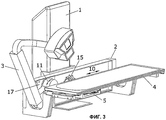
На фиг.3 представлено перспективное изображение рентгеновского аппарата, иллюстрирующее поворот кронштейна узла, содержащего рентгеновскую трубку и коллиматор, независимо от поворотного основания.Figure 3 presents a perspective image of the x-ray apparatus, illustrating the rotation of the bracket of the node containing the x-ray tube and the collimator, regardless of the rotary base.
На фиг.4 представлен вид спереди указанного узла.Figure 4 presents a front view of the specified node.
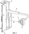
На фиг.5 представлено перспективное изображение, на котором узел, содержащий основание и присоединенные к нему элементы, повернут на угол 90° относительно неподвижной стойки для блока управления и блока питания.Figure 5 presents a perspective image in which the node containing the base and the attached elements are rotated through an angle of 90 ° relative to the fixed rack for the control unit and the power supply.
ПРЕДПОЧТИТЕЛЬНЫЙ ВАРИАНТ РЕАЛИЗАЦИИ ИЗОБРЕТЕНИЯBEST MODE FOR CARRYING OUT THE INVENTION
Далее со ссылками на чертежи описан предпочтительный вариант реализации настоящего изобретения.Next, with reference to the drawings, a preferred embodiment of the present invention is described.
Как показано на фиг.1, предлагаемый рентгеновский аппарат содержит неподвижную стойку (1) для блока управления и блока питания, соединенную с поворотным основанием (2).As shown in figure 1, the proposed x-ray apparatus contains a stationary rack (1) for the control unit and the power supply connected to the rotary base (2).
Поворотное основание (2) неразъемно соединено со складным столом (4) таким образом, что поворот поворотного основания (2) приводит к повороту складного стола (4).The swivel base (2) is inseparably connected to the folding table (4) so that the rotation of the swivel base (2) leads to the rotation of the folding table (4).
К поворотному основанию (2) присоединена опорная пластина (17), на которой установлен U-образный кронштейн (3), на конце которого расположен детектор (5) и узел, содержащий рентгеновскую трубку (6) и коллиматор (7).A support plate (17) is attached to the rotary base (2), on which a U-shaped bracket (3) is mounted, at the end of which there is a detector (5) and a unit containing an x-ray tube (6) and a collimator (7).
Эта опорная пластина (17) может быть присоединена к поворотному основанию (2) таким образом, что поворот этого основания (2) приводит к повороту всех элементов, т.е. складного стола (4), опорной пластины (17) и, следовательно, кронштейна (3) узла, содержащего рентгеновскую трубку (6) и коллиматор, и детектора (5).This support plate (17) can be attached to the rotary base (2) so that the rotation of this base (2) leads to the rotation of all elements, i.e. a folding table (4), a support plate (17) and, therefore, an arm (3) of a unit containing an X-ray tube (6) and a collimator, and a detector (5).
Кроме того, эта опорная пластина (17) может быть частично высвобождена из соединения с вращающимся основанием (2) с обеспечением некоторой степени свободы и возможности перемещения в продольном направлении вдоль длины поворотного основания (2) в наиболее подходящее положение.In addition, this support plate (17) can be partially released from the connection with the rotating base (2) with a certain degree of freedom and the possibility of moving in the longitudinal direction along the length of the rotating base (2) to the most suitable position.
Узел, содержащий поворотное основание (2), вертикально перемещается в продольном направлении (8) относительно неподвижной стойки (1) с обеспечением подъема и спуска всего узла.A node containing a rotary base (2), vertically moves in the longitudinal direction (8) relative to the stationary rack (1) with the provision of lifting and lowering the entire node.
Кроме того, как показано на фиг.5, узел, содержащий поворотное основание (2), можно поворачивать (9) вокруг горизонтальной оси относительно неподвижной стойки (1), что обеспечивает поворот всего узла, содержащего поворотное основание (2) и присоединенные к нему элементы.In addition, as shown in Fig. 5, the assembly containing the rotary base (2) can be rotated (9) about a horizontal axis relative to the stationary stand (1), which allows rotation of the entire assembly containing the rotary base (2) and attached thereto elements.
С другой стороны, при высвобождении опорной пластины (17) из соединения с поворотным основанием (2) опорная пластина и соединенные с ней элементы, т.е. кронштейн (3) и детектор (5), можно перемещать в продольном направлении (10) вдоль поворотного основания (2).On the other hand, when the support plate (17) is released from the connection with the rotary base (2), the support plate and the elements connected thereto, i.e. the bracket (3) and the detector (5) can be moved in the longitudinal direction (10) along the rotary base (2).
На опорной пластине (17) установлены кронштейн (3) узла, содержащего рентгеновскую трубку и коллиматор, и детектор (5), причем кронштейн (3) можно поворачивать (11) относительно опорной пластины (17) независимо от детектора (5). Поворот (11) кронштейна (3) позволяет осуществлять томографическую реконструкцию.The bracket (3) of the assembly containing the x-ray tube and the collimator and the detector (5) are mounted on the support plate (17), and the bracket (3) can be rotated (11) relative to the support plate (17) independently of the detector (5). The rotation (11) of the bracket (3) allows tomographic reconstruction.
Кронштейн (3) также может перемещать узел, содержащий рентгеновскую трубку и коллиматор, вертикально в продольном направлении (12).The bracket (3) can also move the assembly containing the x-ray tube and the collimator vertically in the longitudinal direction (12).
Наконец, складной стол (4) выполнен с возможностью перемещения (13) к поворотному основанию (2) или от него, а также возможностью поворота (14) относительно расположенных на его концах шарниров, что позволяет складывать стол (4) таким образом, что он расположен параллельно поворотному основанию (2).Finally, the folding table (4) is arranged to move (13) to or away from the rotary base (2), and also to rotate (14) relative to the hinges located at its ends, which allows folding the table (4) so that it located parallel to the swivel base (2).
Как показано на фиг.3, опорная пластина (17) высвобождена из соединения с поворотным основанием (2) и перемещена в продольном направлении с открытием отверстия (15) поворотного основания. Опорная пластина (17) имеет некоторую степень свободы и может перемещаться в продольном направлении (10) вдоль поворотного основания (2). Необходимо отметить, что кронштейн (3) можно поворачивать независимо от детектора (5), что позволяет осуществлять томографическую реконструкцию.As shown in FIG. 3, the support plate (17) is released from the connection with the rotary base (2) and is moved in the longitudinal direction with the opening of the hole (15) of the rotary base. The support plate (17) has a certain degree of freedom and can move in the longitudinal direction (10) along the rotary base (2). It should be noted that the bracket (3) can be rotated independently of the detector (5), which allows tomographic reconstruction.
Присоединение опорной пластины (17) к поворотному основанию (2) и ее высвобождение осуществляют с помощью крепежных и высвобождающих средств, расположенных на верхнем и нижнем краях опорной пластины (17).The attachment of the base plate (17) to the rotary base (2) and its release is carried out using fastening and releasing means located on the upper and lower edges of the base plate (17).
На фиг.4 показан вид спереди отверстия (15) для соединения опорной пластины (17) с неподвижной стойкой (1), определяющей ось, относительно которой поворачивают поворотное основание (2). Следует отметить, что это отверстие расположено вблизи одной из сторон неподвижной стойки (1).Figure 4 shows a front view of the hole (15) for connecting the base plate (17) with a fixed column (1) defining an axis about which the pivot base (2) is rotated. It should be noted that this hole is located near one of the sides of the stationary rack (1).
Расположение отверстия (15) и оси поворота вблизи одной из сторон неподвижной стойки (15) означает, что при повороте узла, содержащего поворотное основание (2), со всеми прикрепленными к нему элементами они оказываются расположены на одной стороне неподвижной стойки (1) таким образом, что между узлом, содержащим рентгеновскую трубку (6) и коллиматор (7), и складным столом (4) имеется зазор (16), как показано на фиг.5. Этот зазор (16) непрерывен по всей длине и достаточен для обеспечения прохода носилок, что позволяет получать боковые рентгенограммы пациента без необходимости перемещения пациента с носилок, на которых его доставили.The location of the hole (15) and the axis of rotation near one of the sides of the fixed stand (15) means that when you turn the node containing the rotary base (2), with all the elements attached to it, they are located on the same side of the fixed stand (1) in this way that between the node containing the x-ray tube (6) and the collimator (7), and the folding table (4) there is a gap (16), as shown in Fig.5. This gap (16) is continuous along the entire length and is sufficient to allow passage of the stretcher, which allows obtaining lateral radiographs of the patient without the need to move the patient from the stretcher on which he was delivered.
Настоящее изобретение не ограничено приведенным выше описанием и может быть реализовано специалистами с использованием различных материалов, форм, размеров и конфигураций составляющих элементов.The present invention is not limited to the above description and can be implemented by specialists using various materials, shapes, sizes and configurations of constituent elements.
Claims (3)
неподвижную стойку (1) для блока питания и блока управления;
поворотное основание (2), установленное на неподвижной стойке и выполненное с возможностью перемещения в вертикальном направлении (8) вдоль этой стойки (1) и возможностью поворота (9) вокруг горизонтальной оси относительно этой неподвижной стойки (1);
складной стол (4), присоединенный к поворотному основанию (2);
опорную пластину (17), установленную на поворотном основании и выполненную с возможностью частичного высвобождения из соединения с этим поворотным основанием (2) таким образом, что опорная пластина (17) имеет степень свободы и обеспечена возможностью ее перемещения в продольном направлении (10) по длине поворотного основания (2);
установленные на опорной пластине (17) детектор (5) и кронштейн (3), на котором расположен узел, содержащий рентгеновскую трубку (6) и коллиматор (7);
отличающийся тем, что
кронштейн (3) имеет U-образную форму и выполнен с возможностью перемещения в продольном направлении (12) с подъемом и спуском относительно складного стола (4) и с возможностью поворота (11) относительно опорной пластины (17) независимо от детектора (5).1. X-ray apparatus containing
fixed rack (1) for power supply and control unit;
a swivel base (2) mounted on a stationary rack and made with the possibility of movement in the vertical direction (8) along this rack (1) and the possibility of rotation (9) around a horizontal axis relative to this stationary rack (1);
a folding table (4) attached to the rotary base (2);
a support plate (17) mounted on a rotary base and configured to partially release from the connection with this rotary base (2) so that the support plate (17) has a degree of freedom and is provided with the possibility of its movement in the longitudinal direction (10) along the length swivel base (2);
a detector (5) and an arm (3) mounted on a support plate (17), on which a unit comprising an x-ray tube (6) and a collimator (7) is located;
characterized in that
the bracket (3) has a U-shape and is configured to move in the longitudinal direction (12) with up and down relative to the folding table (4) and with the possibility of rotation (11) relative to the support plate (17) regardless of the detector (5).
Applications Claiming Priority (1)
| Application Number | Priority Date | Filing Date | Title |
|---|---|---|---|
| PCT/ES2009/070054 WO2010100292A1 (en) | 2009-03-04 | 2009-03-04 | X-ray equipment for performing tomosynthesis |
Publications (2)
| Publication Number | Publication Date |
|---|---|
| RU2010149309A RU2010149309A (en) | 2013-04-10 |
| RU2492811C2 true RU2492811C2 (en) | 2013-09-20 |
Family
ID=41396296
Family Applications (1)
| Application Number | Title | Priority Date | Filing Date |
|---|---|---|---|
| RU2010149309/14A RU2492811C2 (en) | 2009-03-04 | 2009-03-04 | X-ray apparatus for tomographic reconstruction |
Country Status (14)
| Country | Link |
|---|---|
| US (1) | US8475040B2 (en) |
| EP (1) | EP2308376B1 (en) |
| JP (1) | JP5501385B2 (en) |
| KR (1) | KR101371341B1 (en) |
| CN (1) | CN102215753B (en) |
| AR (1) | AR078021A1 (en) |
| AU (1) | AU2009341272A1 (en) |
| BR (1) | BRPI0909873A2 (en) |
| CA (1) | CA2727236C (en) |
| ES (1) | ES2403457T3 (en) |
| MX (1) | MX2010013506A (en) |
| RU (1) | RU2492811C2 (en) |
| TW (1) | TW201110942A (en) |
| WO (1) | WO2010100292A1 (en) |
Cited By (3)
| Publication number | Priority date | Publication date | Assignee | Title |
|---|---|---|---|---|
| RU2562013C1 (en) * | 2014-06-25 | 2015-09-10 | Закрытое акционерное общество "Научно-исследовательская производственная компания "Электрон" (ЗАО "НИПК "Электрон"). | General-purpose x-ray imaging system |
| RU2587313C1 (en) * | 2015-04-03 | 2016-06-20 | Закрытое акционерное общество "Научно-исследовательская производственная компания "Электрон" (ЗАО "НИПК "Электрон") | Universal x-ray system |
| RU2785902C1 (en) * | 2021-11-01 | 2022-12-14 | Акционерное общество "МЕДИЦИНСКИЕ ТЕХНОЛОГИИ Лтд" (АО "МТЛ") | Robotic x-ray system |
Families Citing this family (14)
| Publication number | Priority date | Publication date | Assignee | Title |
|---|---|---|---|---|
| CN102430207B (en) * | 2011-09-27 | 2014-07-30 | 重庆德马光电技术有限公司 | Superficial X-ray therapy system |
| CN103784153B (en) * | 2012-11-01 | 2016-04-06 | 上海联影医疗科技有限公司 | The servo-actuated decontrol of a kind of bed systems |
| US9795347B2 (en) * | 2013-10-24 | 2017-10-24 | Institute Of Nuclear Energy Research Atomic Energy Council, Executive Yuan | Scanning system for three-dimensional imaging |
| US9808211B2 (en) * | 2013-11-12 | 2017-11-07 | Carestream Health, Inc. | Head and neck imager |
| USD757271S1 (en) * | 2014-10-31 | 2016-05-24 | Carestream Health, Inc. | Dental mount for cephalometric imaging module |
| USD745970S1 (en) * | 2014-10-31 | 2015-12-22 | Carestream Health, Inc. | Dental arm for cephalometric imaging module |
| UA112351C2 (en) | 2014-11-10 | 2016-08-25 | Сергій Іванович Мірошниченко | X-ray THOMOSYNTHESIS INSTALLATION |
| USD767144S1 (en) * | 2015-04-01 | 2016-09-20 | Shanghai United Imaging Healthcare Co., Ltd. | X-ray digital imaging apparatus |
| UA117599C2 (en) | 2016-05-20 | 2018-08-27 | Сергій Іванович Мірошниченко | MULTI-SENSOR DIGITAL DIGITAL RECEIVER AND PYAMIDAL-X-RAY TOMOGRAPHICAL SUPPLIER |
| CN106691483A (en) * | 2017-01-22 | 2017-05-24 | 上海冠瑞医疗设备股份有限公司 | Pet X-ray photography device with safety protection |
| US10830712B2 (en) * | 2017-03-27 | 2020-11-10 | KUB Technologies, Inc. | System and method for cabinet x-ray systems with camera |
| US20190003982A1 (en) * | 2017-07-03 | 2019-01-03 | The L.S. Starrett Company | Optical Video Measurement System Operable in Multiple Positions |
| FR3084579B1 (en) * | 2018-08-06 | 2020-08-07 | Stephanix | REMOTE CONTROL RADIOLOGY SYSTEM |
| BR102020013650A2 (en) * | 2020-07-02 | 2020-10-20 | Vmi Tecnologias Ltda | X-ray machine with static tube holder / orthogonal bucky with articulated arm with isocentric rotation |
Citations (5)
| Publication number | Priority date | Publication date | Assignee | Title |
|---|---|---|---|---|
| SU940744A1 (en) * | 1981-01-12 | 1982-07-07 | Московский научно-исследовательский институт туберкулеза | Stand to x-ray apparatus |
| FR2821263A1 (en) * | 2001-02-27 | 2002-08-30 | Jacques Gaudel | Remote-controlled patient support device for use in medical radiography or radiotherapy is highly flexible and allows x-ray tube and image receiver to be positioned such that all type of examination can be executed |
| WO2003021629A1 (en) * | 2001-08-28 | 2003-03-13 | Hologic, Inc. | Digital flat panel x-ray receptor positioning in diagnostic radiology |
| RU35211U1 (en) * | 2003-03-19 | 2004-01-10 | Солобоев Сергей Владимирович | The device is x-ray ward |
| US20080240343A1 (en) * | 2007-03-30 | 2008-10-02 | General Electric Company | Portable digital tomosynthesis imaging system and method |
Family Cites Families (14)
| Publication number | Priority date | Publication date | Assignee | Title |
|---|---|---|---|---|
| DE3003976A1 (en) * | 1980-02-04 | 1981-08-13 | Siemens AG, 1000 Berlin und 8000 München | TRIPOD FOR A RETRACTABLE RADIOGENOGRAPHIC IMAGE DETECTION DEVICE UNDER THE PATIENT STORAGE PLATE OF A X-RAY EXAMINATION DEVICE |
| JPH01284231A (en) * | 1988-05-09 | 1989-11-15 | Toshiba Corp | Device for x-ray fluoroscopic photographing |
| US5155757A (en) * | 1990-06-20 | 1992-10-13 | Kabushiki Kaisha Toshiba | X-ray diagnosing apparatus |
| JPH074357B2 (en) * | 1991-06-19 | 1995-01-25 | 株式会社島津製作所 | X-ray fluoroscopy stand |
| JPH07327982A (en) * | 1994-06-08 | 1995-12-19 | Toshiba Corp | X-ray diagnostic device |
| JP2776275B2 (en) * | 1994-10-31 | 1998-07-16 | 株式会社島津製作所 | X-ray fluoroscope |
| JPH09238937A (en) * | 1996-03-11 | 1997-09-16 | Toshiba Corp | Fluoroscopic photographing table for infant |
| JPH11137544A (en) * | 1997-09-02 | 1999-05-25 | Toshiba Corp | Radiographic device |
| JP2000279405A (en) * | 1999-03-30 | 2000-10-10 | Shimadzu Corp | X-ray radiographing device |
| WO2001026132A1 (en) * | 1999-10-06 | 2001-04-12 | Hologic, Inc. | Digital flat panel x-ray detector positioning in diagnostic radiology |
| US6733177B2 (en) * | 2002-09-12 | 2004-05-11 | Ge Medical Systems Global Technology Company, Llc | Friction ring for improved orbital balance of C-arm x-ray apparatus |
| JP4393462B2 (en) * | 2004-01-06 | 2010-01-06 | 株式会社日立メディコ | X-ray equipment |
| US8160205B2 (en) | 2004-04-06 | 2012-04-17 | Accuray Incorporated | Robotic arm for patient positioning assembly |
| JP4851296B2 (en) * | 2006-10-26 | 2012-01-11 | 富士フイルム株式会社 | Radiation tomographic image acquisition apparatus and radiation tomographic image acquisition method |
-
2009
- 2009-03-04 CA CA2727236A patent/CA2727236C/en active Active
- 2009-03-04 AU AU2009341272A patent/AU2009341272A1/en not_active Abandoned
- 2009-03-04 ES ES09784105T patent/ES2403457T3/en active Active
- 2009-03-04 EP EP09784105A patent/EP2308376B1/en active Active
- 2009-03-04 US US12/996,744 patent/US8475040B2/en active Active
- 2009-03-04 WO PCT/ES2009/070054 patent/WO2010100292A1/en active Application Filing
- 2009-03-04 KR KR1020107027450A patent/KR101371341B1/en active IP Right Grant
- 2009-03-04 JP JP2011552475A patent/JP5501385B2/en active Active
- 2009-03-04 CN CN200980146115.9A patent/CN102215753B/en active Active
- 2009-03-04 BR BRPI0909873A patent/BRPI0909873A2/en not_active Application Discontinuation
- 2009-03-04 MX MX2010013506A patent/MX2010013506A/en active IP Right Grant
- 2009-03-04 RU RU2010149309/14A patent/RU2492811C2/en active
-
2010
- 2010-03-03 AR ARP100100627A patent/AR078021A1/en active IP Right Grant
- 2010-03-03 TW TW099106244A patent/TW201110942A/en unknown
Patent Citations (5)
| Publication number | Priority date | Publication date | Assignee | Title |
|---|---|---|---|---|
| SU940744A1 (en) * | 1981-01-12 | 1982-07-07 | Московский научно-исследовательский институт туберкулеза | Stand to x-ray apparatus |
| FR2821263A1 (en) * | 2001-02-27 | 2002-08-30 | Jacques Gaudel | Remote-controlled patient support device for use in medical radiography or radiotherapy is highly flexible and allows x-ray tube and image receiver to be positioned such that all type of examination can be executed |
| WO2003021629A1 (en) * | 2001-08-28 | 2003-03-13 | Hologic, Inc. | Digital flat panel x-ray receptor positioning in diagnostic radiology |
| RU35211U1 (en) * | 2003-03-19 | 2004-01-10 | Солобоев Сергей Владимирович | The device is x-ray ward |
| US20080240343A1 (en) * | 2007-03-30 | 2008-10-02 | General Electric Company | Portable digital tomosynthesis imaging system and method |
Cited By (3)
| Publication number | Priority date | Publication date | Assignee | Title |
|---|---|---|---|---|
| RU2562013C1 (en) * | 2014-06-25 | 2015-09-10 | Закрытое акционерное общество "Научно-исследовательская производственная компания "Электрон" (ЗАО "НИПК "Электрон"). | General-purpose x-ray imaging system |
| RU2587313C1 (en) * | 2015-04-03 | 2016-06-20 | Закрытое акционерное общество "Научно-исследовательская производственная компания "Электрон" (ЗАО "НИПК "Электрон") | Universal x-ray system |
| RU2785902C1 (en) * | 2021-11-01 | 2022-12-14 | Акционерное общество "МЕДИЦИНСКИЕ ТЕХНОЛОГИИ Лтд" (АО "МТЛ") | Robotic x-ray system |
Also Published As
| Publication number | Publication date |
|---|---|
| WO2010100292A1 (en) | 2010-09-10 |
| CN102215753A (en) | 2011-10-12 |
| RU2010149309A (en) | 2013-04-10 |
| AR078021A1 (en) | 2011-10-12 |
| BRPI0909873A2 (en) | 2015-10-06 |
| AU2009341272A1 (en) | 2010-09-10 |
| EP2308376A1 (en) | 2011-04-13 |
| US8475040B2 (en) | 2013-07-02 |
| MX2010013506A (en) | 2011-07-01 |
| KR20110125159A (en) | 2011-11-18 |
| CA2727236C (en) | 2015-08-18 |
| ES2403457T3 (en) | 2013-05-20 |
| TW201110942A (en) | 2011-04-01 |
| CN102215753B (en) | 2014-01-08 |
| US20110135055A1 (en) | 2011-06-09 |
| JP2012519518A (en) | 2012-08-30 |
| KR101371341B1 (en) | 2014-03-06 |
| CA2727236A1 (en) | 2010-09-10 |
| JP5501385B2 (en) | 2014-05-21 |
| EP2308376B1 (en) | 2013-01-30 |
Similar Documents
| Publication | Publication Date | Title |
|---|---|---|
| RU2492811C2 (en) | X-ray apparatus for tomographic reconstruction | |
| US9962132B2 (en) | Multi-directional X-ray imaging system with single support column | |
| US9055912B2 (en) | Supporting device and intra-operative imaging device having the supporting device | |
| US10151810B2 (en) | Pivoting multi-directional X-ray imaging system with a pair of diametrically opposite vertical support columns tandemly movable along a stationary base support | |
| JP7260585B2 (en) | radiation absorbing assembly | |
| JP5372461B2 (en) | Portable tomography diagnostic system with an open gantry | |
| US9039282B2 (en) | Imaging apparatus comprising a ring-shaped gantry | |
| EP2600770B1 (en) | Patient stool for an x-ray imaging apparatus | |
| US20110280379A1 (en) | Imaging apparatus comprising a ring-shaped gantry | |
| US8052325B2 (en) | X-ray fluoroscope table and X-ray fluoroscope system | |
| US11576625B2 (en) | Multi-directional x-ray imaging system | |
| JP7297835B2 (en) | Subject carrier | |
| JP2013524967A5 (en) | ||
| RU2562013C1 (en) | General-purpose x-ray imaging system | |
| RU2328217C2 (en) | Diagnostic scanning digital radiograph | |
| JP4359366B2 (en) | Radiation equipment | |
| JP2008113702A (en) | Radiography equipment | |
| EP0877538A2 (en) | An X-ray apparatus and a method for rearranging such an X-ray apparatus | |
| JP2022523431A (en) | Operating table with integrated imaging device | |
| RU2587313C1 (en) | Universal x-ray system | |
| IT201900002910U1 (en) | EQUIPMENT FOR THE ACQUISITION OF VOLUMETRIC CBCT RADIOGRAPHIES | |
| RU56157U1 (en) | DIAGNOSTIC X-RAY SCANNING DIGITAL APPARATUS | |
| BR102020013650A2 (en) | X-ray machine with static tube holder / orthogonal bucky with articulated arm with isocentric rotation | |
| RU96113127A (en) | MEDICAL VISUALIZING DEVICE FOR PERFORMING A RADIOLOGICAL GENERAL RESEARCH AND / OR STUDY OF THE CARDIOVASCULAR SYSTEM FOR DIAGNOSTIC OR THERAPEUTIC PURPOSES |