RU2492498C2 - Method of determining direction of hydroacoustic transponder beacon on horizontal and vertical angle - Google Patents
Method of determining direction of hydroacoustic transponder beacon on horizontal and vertical angle Download PDFInfo
- Publication number
- RU2492498C2 RU2492498C2 RU2011146852/28A RU2011146852A RU2492498C2 RU 2492498 C2 RU2492498 C2 RU 2492498C2 RU 2011146852/28 A RU2011146852/28 A RU 2011146852/28A RU 2011146852 A RU2011146852 A RU 2011146852A RU 2492498 C2 RU2492498 C2 RU 2492498C2
- Authority
- RU
- Russia
- Prior art keywords
- cos
- plane
- transducers
- coordinate system
- signal
- Prior art date
Links
Images

Landscapes
- Measurement Of Velocity Or Position Using Acoustic Or Ultrasonic Waves (AREA)
Abstract
Description
Изобретение относится к области гидроакустики и может быть использовано для определения направления на гидроакустический маяк-ответчик.The invention relates to the field of sonar and can be used to determine the direction of the sonar beacon responder.
Известен способ обнаружения шумящих в море объектов в фиксированном частотном диапазоне, при котором принимают шумовые сигналы в горизонтальной и вертикальной плоскостях многоэлементной антенной решеткой гидролокатора и осуществляют первичную обработку, для чего преобразуют в цифровую форму напряжения шумовых сигналов антенной решетки, выполняют преобразование Фурье отсчетов напряжений шумовых сигналов антенной решетки, вычисляют для каждого из полученных частотных отсчетов амплитудные и фазовые коэффициенты синфазного сложения напряжений сигналов антенной решетки, суммируют выходные напряжения сигналов антенной решетки с постоянными весами, равными произведению амплитудных и фазовых коэффициентов, чем образуют пространственные каналы наблюдения в горизонтальной и вертикальной плоскостях, квадрируют и осуществляют вторичную обработку на каждом цикле обзора, для чего суммируют по всем частотным отсчетам выходные напряжения образованных пространственных каналов в фиксированном частотном диапазоне, усредняют по времени, центрируют и нормируют шумовые сигналы к помехе, осуществляют наблюдение на каждом цикле обзора полученных отметок принятых шумовых сигналов и принимают решение об обнаружении путем сравнения с пороговым значением отношения сигнал-помеха, отличающийся тем, что на каждом цикле обзора до квадрирования для каждого частотного отсчета формируют адаптивные пространственные каналы наблюдения, каждый из которых образован, по крайней мере, тремя смежными пространственными каналами в горизонтальной или в вертикальной плоскости, для чего формируют взаимные спектры мощности между шумовыми сигналами пространственных каналов, участвующих в формировании адаптивного пространственного канала наблюдения, накапливают взаимные спектры мощности шумовых сигналов для заданного времени накопления, составляют матрицу накопленных взаимных спектров мощности шумовых сигналов и осуществляют ортогональное преобразование матрицы, вычисляют векторы фазовых коэффициентов синфазного сложения сигналов пространственных каналов, участвующих в формировании адаптивного пространственного канала наблюдения, вычисляют вектор выходных напряжений пространственных каналов, участвующих в формировании адаптивного пространственного канала путем решения векторно-матричного уравнения для ортогонально преобразованной матрицы накопленных взаимных спектров мощности и вектора фазовых коэффициентов синфазного сложения сигналов, квадрирование производят, вычисляя отклик полученного адаптивного пространственного канала наблюдения, равного обратной величине суммы квадратов элементов вектора выходных напряжений, а вторичную обработку осуществляют для выходных напряжений адаптивных пространственных каналов наблюдения (см. описание изобретения к патенту РФ №2339050, МПК G01S 3/80, G01S 15/04, публикация 20.11.2008).A known method of detecting objects that are noisy at sea in a fixed frequency range, in which noise signals are received in the horizontal and vertical planes by a multi-element sonar array and carry out initial processing, for which the voltage of the noise signals of the antenna array is digitized, Fourier transform of the samples of noise signal voltages is performed antenna array, the amplitude and phase coefficients of the in-phase addition are calculated for each of the obtained frequency samples voltage signals of the antenna array, summarize the output voltage of the signals of the antenna array with constant weights equal to the product of the amplitude and phase coefficients, which form the spatial observation channels in the horizontal and vertical planes, quadrate and perform secondary processing on each review cycle, for which they are summed over all frequency samples output voltages of the formed spatial channels in a fixed frequency range, averaged over time, center and normalize the noise signals the interference channels, they observe on each review cycle the received marks of the received noise signals and make a decision to detect, by comparing with the threshold value, the signal-to-noise ratio, characterized in that adaptive spatial observation channels are formed on each review cycle prior to squaring, each of which is formed by at least three adjacent spatial channels in the horizontal or vertical plane, for which mutual power spectra of the noise signals of the spatial channels involved in the formation of the adaptive spatial observation channel, accumulate the mutual power spectra of the noise signals for a given accumulation time, compose a matrix of the accumulated mutual power spectra of the noise signals and perform orthogonal transformation of the matrix, calculate the phase coefficient vectors of the in-phase addition of the signals of the spatial channels involved in the formation of an adaptive spatial observation channel, a vector is calculated the output voltages of the spatial channels involved in the formation of the adaptive spatial channel by solving the vector-matrix equation for the orthogonally transformed matrix of the accumulated mutual power spectra and the vector of phase coefficients of the in-phase addition of signals, the squaring is performed by calculating the response of the resulting adaptive spatial observation channel equal to the inverse of the sum of the squares of the elements vectors of output voltages, and secondary processing is carried out for output n stresses adaptive spatial channel monitoring (see. Description of the invention to RF patent No. 2339050, IPC G01S 3/80, G01S 15/04, publication November 20, 2008).
Недостатком известного способа является невозможность его применения в случае использования ограниченных аппаратных ресурсов.The disadvantage of this method is the impossibility of its application in the case of using limited hardware resources.
Известен способ адаптивной пространственной фильтрации сигналов, заключающийся в приеме сигналов в N пространственно разнесенных точках, где N≥2, расчете весовых коэффициентов, взвешенном суммировании принятых сигналов, в котором генерируют первый и второй опорные сигналы с различными частотами, разделяют каждый из них на N равноамплитудных составляющих, сдвигают по фазе каждую составляющую на предварительно заданную величину фазы, после чего i-й принятый сигнал, где i=1, 2, … N, и i-e составляющие первого и второго опорных сигналов суммируют, причем i-й весовой коэффициент рассчитывают по формулеA known method of adaptive spatial filtering of signals, which consists in receiving signals at N spatially separated points, where N≥2, calculating weight coefficients, weighted summation of the received signals, in which the first and second reference signals with different frequencies are generated, divide each of them into N equally amplitude components, phase-shift each component by a predetermined phase value, after which the i-th received signal, where i = 1, 2, ... N, and ie the components of the first and second reference signals, I summarize , The i-th weighting factor is calculated by the formula
![]()
![]()
где Wi(t) - текущее значение i-го весового коэффициента;where W i (t) is the current value of the i-th weight coefficient;
Wyi - значение i-го управляющего сигнала;W yi is the value of the i-th control signal;
Δt - интервал временной дискретизации;Δt is the time sampling interval;
Y(t) - взвешенно суммированный сигнал;Y (t) is the weighted summed signal;
Zi(t) - суммарный сигнал от сложения i-го принятого сигнала и i-x составляющих первого и второго опорных сигналов;Z i (t) is the total signal from the addition of the i-th received signal and ix components of the first and second reference signals;
* - обозначение операции комплексного сопряжения;* - designation of the operation of complex pairing;
µ - коэффициент усиления (передачи), а частоты первого ω1 и второго ω2 опорных сигналов выбирают из условия ω1<(ω0-Δω), ω2>(ω0+Δω), где ω0 и Δω соответственно несущая частота и ширина спектра принимаемого полезного сигнала (см. описание изобретения к патенту РФ №2141706, МПК H01Q 21/00, публикация 20.11.1999).µ is the gain (transmission), and the frequencies of the first ω 1 and second ω 2 reference signals are selected from the condition ω 1 <(ω 0 -Δω), ω 2 > (ω 0 + Δω), where ω 0 and Δω are the carrier frequencies, respectively and the width of the spectrum of the received useful signal (see the description of the invention to the patent of the Russian Federation No. 2141706, IPC H01Q 21/00, publication November 20, 1999).
К недостаткам указанного выше способа можно отнести использование опорных сигналов с предустановленной несущей частотой, что в условиях наличия доплеровского сдвига частоты в результате взаимного движения источника и приемника сигнала приведет к расстройке контура обработки сигнала.The disadvantages of the above method include the use of reference signals with a predefined carrier frequency, which in the presence of a Doppler frequency shift as a result of the mutual movement of the source and receiver of the signal will lead to mismatch of the signal processing loop.
Известен способ формирования диаграмм направленности N-элементной линейной эквидистантной антенной решетки, заключающийся в том, что сигналы с элементов антенной решетки усиливают, ограничивают в полосе частот и осуществляют преобразование Фурье каждого сигнала, осуществляют инвертирование преобразованного сигнала первого элемента и его попарное суммирование с преобразованными сигналами последующих элементов, для каждого из полученных (N-1) сигналов измеряют спектральную плотность мощности, умножают их на вещественные весовые коэффициенты An, которые определяют из соотношенияA known method of forming radiation patterns of an N-element linear equidistant antenna array, which consists in the fact that the signals from the antenna array elements are amplified, limited in the frequency band and Fourier transform of each signal, the converted signal of the first element is inverted and its pairwise summation with converted signals of subsequent elements, for each of the received (N-1) signals the spectral power density is measured, multiplied by real weight coefficients itsienty A n, which is determined from the relation
An=sin[nπ(N-1)/N]/n,A n = sin [nπ (N-1) / N] / n,
где n=1, (N-1),where n = 1, (N-1),
эти сигналы суммируют и суммарный сигнал подвергают частотной фильтрации, амплитудно-частотную характеристику которой выбирают пропорционально функцииthese signals are summed and the total signal is subjected to frequency filtering, the amplitude-frequency characteristic of which is selected in proportion to the function
где d - расстояние между соседними элементами;where d is the distance between adjacent elements;
c - скорость распространения волновых процессов в среде;c is the propagation velocity of wave processes in the medium;
α - угол между направлением главного лепестка диаграммы направленности и нормалью к плоскости апертуры (см. описание изобретения к авторскому свидетельству СССР №1327026, МПК G01S 3/80, H01Q 3/26, публикация 30.07.1987).α is the angle between the direction of the main lobe of the radiation pattern and the normal to the plane of the aperture (see the description of the invention for the USSR copyright certificate No. 1327026, IPC G01S 3/80, H01Q 3/26, publication July 30, 1987).
К недостаткам данного метода можно отнести ограниченность его применения только областью линейных эквидистантных антенных решеток, а значит с его помощью можно определить либо только горизонтальный, либо только вертикальный угол направления на источник сигнала.The disadvantages of this method include the limited use of it only in the field of linear equidistant antenna arrays, which means that it can be used to determine either only the horizontal or only the vertical direction angle to the signal source.
Известен способ обзора пространства гидроакустической системой, включающий прием акустического сигнала в водной среде с помощью неподвижной гидроакустической антенны, преобразование акустического сигнала в электрические колебания, усиление и частотную фильтрацию этих колебаний, формирование N направлений пространственной фильтрации в пространстве обзора, сдвинутых относительно друг друга на угол 

где G1(f), G2(f) энергетические спектры, соответствующие соседним направлениям пространственной фильтрации;where G 1 (f), G 2 (f) energy spectra corresponding to neighboring spatial filtering directions;
R(Θx) любая из характеристик направленности статического веера, причем Θx определяют для каждой из частот спектрального анализа в рабочем диапазоне,R (Θ x ) any of the directivity characteristics of a static fan, and Θ x is determined for each of the frequencies of the spectral analysis in the working range,
после чего усредняют по ансамблю полученные данные, при этом после сопоставления энергетических спектров G1(f) и G2(f) подавляют сигналы в направлениях с меньшими значениями энергетических спектров на всех частотах (см. описание изобретения к патенту РФ №2047278, МПК G01S 7/52, H04R 1/44, публикация 27.10.1995).after which the data are averaged over the ensemble, while after comparing the energy spectra G 1 (f) and G 2 (f), the signals are suppressed in directions with lower values of the energy spectra at all frequencies (see the description of the invention to RF patent No. 2047278, IPC G01S 7/52, H04R 1/44, publication October 27, 1995).
К недостаткам данного способа можно отнести необходимость построения веера характеристик направленности антенной решетки, что приводит к большим вычислительным затратам, а значит невозможности его реализации в условиях использования ограниченных вычислительных ресурсов.The disadvantages of this method include the need to build a fan of the directivity of the antenna array, which leads to high computational costs, and therefore the impossibility of its implementation in terms of using limited computing resources.
Известен способ подледного приема сигналов спутниковых навигационных систем при нахождении подводного объекта на горизонте плавания с использованием гидроакустического канала передачи навигационной информации, включающий ввод в лед антенны приемника спутниковой навигационной системы в месте приледнения данной антенны к нижней кромке льда, прием этой антенной сигналов космических аппаратов, измерение приемником параметров этих сигналов и по полученным данным определение вычислительным путем искомых поправок к геодезическим счислимым координатам и курсу, вырабатываемых бортовой инерциальной навигационной системой подводного объекта, осуществление путем учета данных поправок коррекции бортовой инерциальной навигационной системы, в котором доставляют от горизонта плавания подводного объекта до места приледнения к нижней кромки льда антенну с приемником сигналов спутниковой навигационной системы и с механизмом внедрения ее в лед, двухканальный маяк-ответчик, который имеет разные коды запроса и разную частоту излучаемого гидроакустического сигнала, измеритель скорости распространения звука в воде и гидростатический датчик, внедряют антенну с приемником сигналов спутниковой навигационной системы в лед в месте ее приледнения к нижней кромке льда с помощью механизма внедрения до момента выхода данной антенны изо льда в воздушную среду, а на подводном объекте используют двухканальную гидроакустическую систему с двумя гидроакустическими приемоизлучающими антеннами, одну приемоизлучающую гидроакустическую антенну устанавливают в заданном месте в корме, а другую гидроакустическую приемоизлучающую антенну устанавливают в заданном месте в носу подводного объекта, при этом две данные антенны располагают вдоль направления его диаметральной плоскости или под известным углом к ней, определяют геодезические координаты маяка-ответчика приемником сигналов спутниковой навигационной системы, в период подъема до нижней кромки льда антенны с приемником сигналов спутниковой навигационной системы и их погружения до подводного объекта измеряют гидростатическое давление воды гидростатическим датчиком, а также скорость звука в воде измерителем скорости звука, а на подводном объекте синхронно излучают в направлении маяка-ответчика сигналы «запроса» одной и второй гидроакустическими приемоизлучающими антеннами и принимают переизлученные сигналы маяка-ответчика данными антеннами, по измеренным параметрам которых определяют вычислительным путем наклонные расстояния от подводного объекта до маяка-ответчика и пеленги на маяк-ответчик из двух заданных мест установки данных двух гидроакустических приемоизлучающих антенн двухканальной навигационной гидроакустической системы (см. описание изобретения к патенту РФ №2398316, МПК H01Q 1/04, публикация 27.08.2009).There is a method of sub-ice reception of satellite navigation system signals when the underwater object is on the horizon using a hydroacoustic channel for transmitting navigation information, which includes inputting the antenna of the satellite navigation system receiver into ice at the location of the antenna near the lower ice edge, receiving spacecraft signals from this antenna, measuring the receiver of the parameters of these signals and, based on the data obtained, the computational determination of the desired corrections to geodetic numbers the coordinates and heading generated by the onboard inertial navigation system of the underwater object, by taking into account these corrections, the correction of the onboard inertial navigation system, in which an antenna with a satellite navigation system signal receiver and with an implementation mechanism is delivered from the navigation horizon of the underwater object to the point of ice adhering to the lower ice edge measure it into ice, a two-channel transponder beacon that has different request codes and different frequencies of the emitted sonar signal, measure l the speed of sound propagation in water and a hydrostatic sensor, they introduce an antenna with a satellite navigation system signal receiver into the ice at the place of its adhering to the lower edge of the ice using the introduction mechanism until this antenna emerges from the ice into the air, and a two-channel sonar is used on the underwater object a system with two hydro-acoustic receiving-radiating antennas, one receiving-radiating hydro-acoustic antenna is installed in a given place in the stern, and the other hydro-acoustic receiving-radiating the teaching antenna is installed in a predetermined place in the nose of the underwater object, while two of these antennas are placed along the direction of its diametrical plane or at a known angle to it, the geodetic coordinates of the responder beacon are determined by the signal receiver of the satellite navigation system, during the rise to the lower ice edge of the antenna with the receiver of the signals of the satellite navigation system and their immersion to the underwater object measure the hydrostatic pressure of water with a hydrostatic sensor, as well as the speed of sound in water a sound speed measuring instrument, and on an underwater object synchronously emit “request” signals in the direction of the responder beacon by one and the second hydro-acoustic receiving-emitting antennas and receive re-emitted signals of the responder beacon with these antennas, the measured parameters of which determine the slope distances from the underwater object to the beacon of the transponder and bearings to the beacon-transponder from two predetermined data locations of two sonar transceiving antennas of a two-channel navigation sonar system (see Description of the invention to the patent of the Russian Federation No. 2398316, IPC H01Q 1/04, publication August 27, 2009).
К недостаткам данного изобретения можно отнести применение двух гидроакустических приемоизлучающих антенн, которые необходимо установить в носу и корме судна носителя (так называемая система с длинной базой), что не всегда возможно.The disadvantages of this invention include the use of two sonar transceiver antennas, which must be installed in the bow and stern of the carrier vessel (the so-called system with a long base), which is not always possible.
Задачей заявляемого изобретения является уменьшение вычислительных затрат на выполнение процедуры определения направления на гидроакустический маяк-ответчик при обработке сигналов, принятых преобразователями антенной решетки. Уменьшение вычислительных затрат достигается тем, что в предлагаемом способе отсутствует процедура вычисления пространственного спектра или веера диаграмм направленности антенной решетки для всех возможных направлений прихода сигнала от маяка-ответчика. Вместо этого на основе относительных задержек прихода фронта волны сигнала, измеренных для пар преобразователей, аналитическим способом вычисляется направление прихода сигнала от маяка-ответчика. Данный метод эффективен для антенных решеток с небольшим количеством преобразователей при применении в качестве ответного сигнала маяка-ответчика сложного навигационного сигнала с фазовой манипуляцией по закону м-последовательности или с линейной частотной модуляцией.The objective of the invention is to reduce the computational cost of performing the procedure for determining the direction of the sonar beacon responder when processing signals received by the transducers of the antenna array. The reduction in computational costs is achieved by the fact that in the proposed method there is no procedure for calculating the spatial spectrum or fans of the radiation patterns of the antenna array for all possible directions of the signal from the transponder beacon. Instead, based on the relative arrival time delays of the signal front measured for pairs of transducers, the direction of arrival of the signal from the transponder beacon is calculated in an analytical way. This method is effective for antenna arrays with a small number of converters when using a complex navigation signal with phase shift keying according to the law of m-sequence or with linear frequency modulation as a response signal from a responder beacon.
Сущность заявляемого изобретения заключается в следующем.The essence of the claimed invention is as follows.
Способ определения направления на гидроакустический маяк-ответчик по горизонтальному и вертикальному углу, включающий излучение судном сигнала запроса и прием пространственной антенной решеткой сигнала ответа от маяка-ответчика, пространственную антенную решетку разбивают на набор плоскостей таким образом, чтобы каждая плоскость образовывалась акустическими центрами трех или четырех преобразователей, лежащих на двух взаимно пересекающихся прямых, с каждой плоскостью связывают свою прямоугольную систему координат и вычисляют горизонтальный и вертикальный углы направления на источник сигнала, для чего преобразователи, акустические центры которых образуют данную плоскость, разбивают на две пары, сигнал оцифровывают с частотой дискретизации Fs, вычисляют взаимную корреляционную функцию сигналов x1 и x2, принятых преобразователями каждой пары по формуле:The method for determining the direction to the hydroacoustic transponder beacon according to the horizontal and vertical angles, including the radiation of the request signal by the ship and receiving the response signal from the transponder beacon by the spatial antenna array, the spatial antenna array is divided into a set of planes so that each plane is formed by three or four acoustic centers transducers lying on two mutually intersecting lines, with each plane they connect their rectangular coordinate system and calculate the mountains zontally and vertical angle direction to the source signal, which transducers acoustic centers form a given plane, divided into two pairs, the signal is digitized with a sampling frequency F s, is calculated mutual correlation function of signals x 1 and x 2 taken transducers of each pair of the formula :
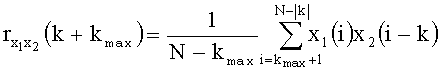
где k - аргумент взаимной корреляционной функции соответствующий сдвигу в отсчетах двух сигналов x1 и x2, изменяющийся в диапазоне - kmax≤k≤kmax;where k is the argument of the mutual correlation function corresponding to the shift in the samples of two signals x 1 and x 2 , varying in the range - k max ≤k≤k max ;
![]()
![]()
- количество отсчетов максимально возможной с задержки сигнала на преобразователях одной пары;- the number of samples maximum possible with a signal delay on the converters of one pair;
N - количество отсчетов анализируемого фрагмента сигнала;N is the number of samples of the analyzed fragment of the signal;
и для каждой пары преобразователей вычисляют разность моментов времени прихода плоского фронта волны к преобразователям:and for each pair of transducers calculate the difference in moments of time of arrival of a plane wave front to the transducers:
![]()
![]()
где ![]()
![]()
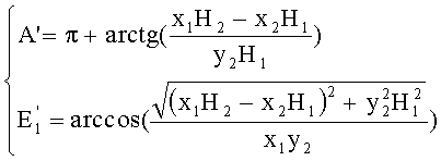
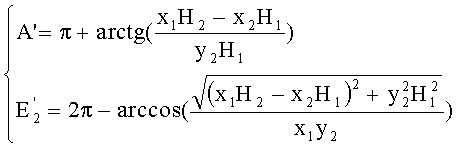
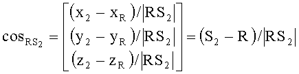
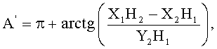
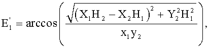
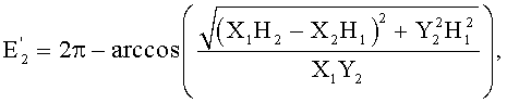
затем для каждой плоскости по найденным относительным задержкам для двух пар преобразователей и известным координатам акустических центров преобразователей вычисляют горизонтальный A′ и вертикальный E′ углы направления на источник сигнала в системе координат O′X′Y′Z′ соответствующей плоскости:then, for each plane, based on the found relative delays for the two pairs of transducers and the known coordinates of the acoustic centers of the transducers, the horizontal A ′ and vertical E ′ angles of direction to the signal source in the coordinate system O′X′Y′Z ′ of the corresponding plane are calculated:


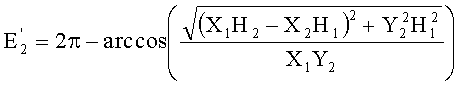
где X1=x1-x3 - разность абсцисс акустических центров преобразователей 1 и 3, образующих плоскость;where X 1 = x 1 -x 3 - the difference of the abscissas of the acoustic centers of the transducers 1 and 3, forming a plane;
X2=x2-x4 - разность абсцисс акустических центров преобразователей 2 и 4;X 2 = x 2 -x 4 - the difference of the abscissas of the acoustic centers of the
H1=h1-h3, где h1 и h3 - расстояние, проходимое плоским фронтом волны от преобразователей 1 и 3 до начала системы координат, связанной с рассматриваемой плоскостью;H 1 = h 1 -h 3 , where h 1 and h 3 - the distance traveled by the plane wave front from the transducers 1 and 3 to the origin of the coordinate system associated with the plane in question;
H2=h2-h3, где h2 и h3 - расстояния, проходимые плоским фронтом волны от преобразователей 2 и 3 до начала системы координат, связанной с рассматриваемой плоскостью;H 2 = h 2 -h 3 , where h 2 and h 3 are the distances traveled by the plane wave front from transducers 2 and 3 to the origin of the coordinate system associated with the plane in question;
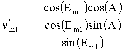
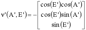
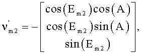
затем для каждого направления, задаваемого значениями горизонтального и вертикального углов, вычисляют единичный вектор в прямоугольной системе координат, связанной с каждой из плоскостей:then, for each direction specified by the values of horizontal and vertical angles, a unit vector is calculated in a rectangular coordinate system associated with each of the planes:

где ![]()
![]()
![]()
![]()
![]()
![]()
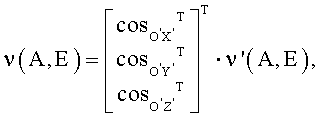
и выполняют перевод прямоугольных координат найденных векторов в систему координат, связанную с антенной решеткой, по формуле:and translate the rectangular coordinates of the vectors found into the coordinate system associated with the antenna array, according to the formula:
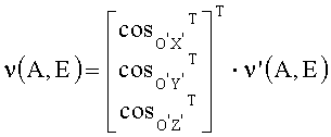
где cosO′X′ - направляющий косинус оси O'X' в системе координат OXYZ;where cos O′X ′ is the direction cosine of the axis O'X 'in the coordinate system OXYZ;
cosO′Y′ - направляющий косинус оси O'Y' в системе координат OXYZ;cos O′Y ′ is the direction cosine of the O'Y 'axis in the OXYZ coordinate system;
cosO′Z′ - направляющий косинус оси O'Z' в системе координат OXYZ;cos O′Z ′ is the direction cosine of the O'Z 'axis in the OXYZ coordinate system;
после вычисления векторов ![]()
![]()
![]()
![]()
![]()
![]()

![]()
![]()
где ![]()
![]()
![]()
![]()
![]()
![]()
это позволяет определить значения горизонтального A и вертикального E углов, задающих направление на гидроакустический маяк-ответчик.this allows you to determine the values of horizontal A and vertical E angles that specify the direction to the sonar beacon responder.
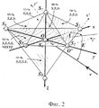
Сущность заявляемого изобретения поясняется чертежами: где на фиг.1 показана антенная решетка со своей системой координат OXYZ и фронт волны акустического сигнала маяка-ответчика:The essence of the claimed invention is illustrated by the drawings: where in Fig.1 shows an antenna array with its coordinate system OXYZ and the wavefront of the acoustic signal of the beacon-transponder:
S1÷S7, Si - акустические центры преобразователей; α0 - плоскость фронта волны принимаемого антенной сигнала в момент времени t=0, αi - в момент времени t=ti, когда фронт достигает преобразователя Si; ν - нормаль к плоскости фронта волны, ri - радиус-вектор преобразователя Si, hi - расстояние между фронтами волны в момент времени t=ti и t=0; A и E - горизонтальный и вертикальный углы направления на источник сигнала - гидроакустический маяк-ответчик;S 1 ÷ S 7 , S i - acoustic centers of the transducers; α 0 is the plane of the wave front of the signal received by the antenna at time t = 0, α i is at time t = t i when the front reaches the converter S i ; ν is the normal to the plane of the wave front, r i is the radius vector of the transducer S i , h i is the distance between the wave fronts at time t = t i and t = 0; A and E - horizontal and vertical angles of direction to the signal source - sonar transponder beacon;
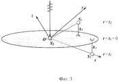
на фиг.2 показано разбиение антенной решетки на плоскости:figure 2 shows a partition of the antenna array in the plane:
S1÷S7 - акустические центры преобразователей; ν - нормаль к плоскости фронта волны - вектор, задающий направление прихода сигнала; A и E - горизонтальный и вертикальный углы направления на источник сигнала - гидроакустический маяк-ответчик; OXYZ - система координат антенной решетки, O'X'Y'Z' - система координат, связанная с плоскостью преобразователей S2S3S7.;S 1 ÷ S 7 - acoustic centers of the transducers; ν - normal to the plane of the wave front - a vector that sets the direction of arrival of the signal; A and E - horizontal and vertical angles of direction to the signal source - sonar transponder beacon; OXYZ - coordinate system of the antenna array, O'X'Y'Z '- coordinate system associated with the plane of the transducers S 2 S 3 S 7 .;
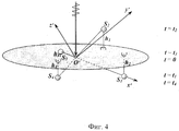
на фиг.3 показана плоскость со связанной системой координат O'X'Y'Z', образованная тремя преобразователями S1, S2, S3, и ее расположение относительно фронта волны в момент времени t=0; t1 и t2 - моменты времени, когда фронт волны достигает преобразователи S1 и S2 соответственно, h1 и h2 - расстояния, измеренные относительно нулевого положения, проходимые фронтом волны при достижении преобразователей S1 и S2 соответственно;figure 3 shows a plane with an associated coordinate system O'X'Y'Z ', formed by three transducers S 1 , S 2 , S 3 , and its location relative to the wave front at time t = 0; t 1 and t 2 are times when the wave front reaches the transducers S 1 and S 2, respectively, h 1 and h 2 are the distances measured relative to the zero position traveled by the wave front when the transducers S 1 and S 2 are reached, respectively;
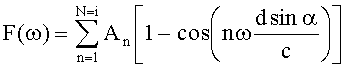
на фиг.4 показана плоскость со связанной системой координат O'X'Y'Z', образованная двумя парами преобразователей S1, S3 и S2, S4, и расположение ее относительно фронта волны в момент времени t=0; t1, t2, t3, t4 - моменты времени, когда фронт волны достигают преобразователи S1, S2, S3 и S4 соответственно; h1, h2, h3, h4 - расстояния, измеренные относительно нулевого положения, проходимые фронтом волны при достижении преобразователей S1, S2, S3 и S4 соответственно;figure 4 shows a plane with an associated coordinate system O'X'Y'Z 'formed by two pairs of transducers S 1 , S 3 and S 2 , S 4 , and its location relative to the wave front at time t = 0; t 1 , t 2 , t 3 , t 4 - time instants when the wavefront reaches the transducers S 1 , S 2 , S 3 and S 4, respectively; h 1 , h 2 , h 3 , h 4 - distances measured relative to the zero position traveled by the wave front when converters S 1 , S 2 , S 3 and S 4 are reached, respectively;
на фиг.5 показаны координаты ![]()
![]()
![]()
![]()
![]()
![]()
![]()
![]()
Заявляемый способ осуществляют следующим образом.The inventive method is as follows.
С пространственной антенной решеткой связывают трехмерную прямоугольную систему координат OXYZ, ось OZ которой направлена вниз для удобства, так как вертикальный угол под водой отсчитывают от плоскости OXY вниз. Радиус-вектор произвольного преобразователя Si в системе координат OXYZ обозначим как ri=[xi yi zi]T. Расположение преобразователей и системы координат показано на фиг.1.A three-dimensional rectangular coordinate system OXYZ is connected to the spatial antenna array, the OZ axis of which is directed downward for convenience, since the vertical angle under water is counted down from the OXY plane. The radius vector of an arbitrary transducer S i in the coordinate system OXYZ is denoted by r i = [x i y i z i ] T. The location of the transducers and the coordinate system is shown in figure 1.
В описываемом способе делают следующие допущения: каждый преобразователь считают точкой, координаты которой совпадают с акустическим центром преобразователя; ввиду относительной удаленности источника сигнала от антенны, по сравнению с расстояниями между преобразователями, фронт волны, приходящий к каждому преобразователю, считают плоским.In the described method, the following assumptions are made: each transducer is considered a point whose coordinates coincide with the acoustic center of the transducer; in view of the relative distance of the signal source from the antenna, compared with the distances between the transducers, the wavefront coming to each transducer is considered flat.
Направление на источник сигнала задают горизонтальным и вертикальным углами - вектором [A, E] в сферической системе координат с началом координат в точке O. Горизонтальный угол A - угол между осью OX и проекцией вектора направления на плоскость OXY, отсчитывают от оси OX по часовой стрелке, если смотреть на плоскость OXY сверху. Вертикальный угол E - угол между вектором направления на источник и его проекцией на плоскость OXY и отсчитывают от плоскости OXY вниз (см. фиг.1).The direction to the signal source is set by the horizontal and vertical angles - the vector [A, E] in the spherical coordinate system with the origin at the point O. The horizontal angle A is the angle between the OX axis and the projection of the direction vector onto the OXY plane, counted clockwise from the OX axis if you look at the OXY plane from above. The vertical angle E is the angle between the direction vector to the source and its projection onto the OXY plane and is counted down from the OXY plane (see Fig. 1).
Плоскости фронта волны α0 и αi, схематически показаны на фиг.1 эллипсами. Направление на источник сигнала есть нормаль к плоскости фронта волны - вектор ν на фиг.1. Благодаря пространственной удаленности преобразователей, фронт волны сигнала от источника излучения достигнет преобразователей в разные моменты времени. Для расчетов необходимы только относительные времена прихода сигнала к преобразователям, поэтому для удобства расчетов за t=0 принимают момент времени, когда плоский фронт волны достигнет точки O - начала системы координат антенной решетки. Фронт волны достигает i-й преобразователь в момент времени t=ti, причем, если преобразователь находится ближе к источнику чем т.O, то знак у ti будет отрицательный, а если дальше - положительный.The plane of the wave front α 0 and α i are schematically shown in figure 1 by ellipses. The direction to the signal source is normal to the plane of the wave front - the vector ν in figure 1. Due to the spatial remoteness of the transducers, the wavefront of the signal from the radiation source reaches the transducers at different points in time. For calculations, only the relative arrival times of the signal to the converters are necessary, therefore, for the convenience of calculations, for t = 0, we take the time moment when the plane wave front reaches point O - the origin of the antenna array coordinate system. The wave front reaches the i-th transducer at time t = t i , and if the transducer is closer to the source than t.O, then the sign of t i will be negative, and if it is positive further.
Пространственная антенная решетка разбивают на набор плоскостей. Пример объединения преобразователей антенной решетки в плоскости представлен на фиг.2. Каждая плоскость образуют акустическими центрами трех или четырех преобразователей антенной решетки. В случае образования плоскости четырьмя преобразователями их акустические центры должны лежать на двух взаимно пересекающихся прямых. Выбор разбиения антенной решетки на плоскости должен производиться так, чтобы плоскости, образованные акустическими центрами преобразователей, не совпадали друг с другом.The spatial antenna array is divided into a set of planes. An example of combining the transducers of the antenna array in the plane is presented in figure 2. Each plane is formed by the acoustic centers of three or four transducers of the antenna array. In the case of the formation of a plane by four transducers, their acoustic centers should lie on two mutually intersecting straight lines. The choice of dividing the antenna array into planes should be made so that the planes formed by the acoustic centers of the transducers do not coincide with each other.
С каждой плоскостью связывают свою прямоугольную систему координат (на фиг.2 показана система координат O'X'Y'Z', связанная с плоскостью преобразователей S2S3S7) и вычисляют горизонтальный и вертикальный углы направления на источник сигнала в системе координат соответствующей плоскости преобразователей. Для этого преобразователи, акустические центры которых образуют данную плоскость, разбивают на две пары. В случае трех преобразователей один из преобразователей будет общим для обоих пар. Для каждой пары преобразователей вычисляют разность моментов времени прихода фронта волны к преобразователям - относительная задержка. Для этого сигнал оцифровывают с частотой дискретизации Fs, вычисляют взаимную корреляционную функцию сигналов x1 и x2, принятых преобразователями каждой пары по формуле:Each plane is associated with its own rectangular coordinate system (Fig. 2 shows the coordinate system O'X'Y'Z 'associated with the plane of the transducers S 2 S 3 S 7 ) and the horizontal and vertical angles of direction to the signal source in the coordinate system of the corresponding transducer planes. For this, transducers whose acoustic centers form a given plane are divided into two pairs. In the case of three transducers, one of the transducers will be common to both pairs. For each pair of transducers, the difference in the times of arrival of the wave front to the transducers is calculated - the relative delay. For this, the signal is digitized with a sampling frequency F s , the mutual correlation function of the signals x 1 and x 2 received by the transducers of each pair is calculated by the formula:
где k - аргумент взаимной корреляционной функции соответствующий сдвигу в отсчетах двух сигналов x1 и x2, изменяющийся в диапазоне - kmax≤k≤kmax;where k is the argument of the mutual correlation function corresponding to the shift in the samples of two signals x 1 and x 2 , varying in the range - k max ≤k≤k max ;
![]()
![]()
- количество отсчетов максимально возможной с задержки сигнала на преобразователях одной пары;- the number of samples maximum possible with a signal delay on the converters of one pair;
N - количество отсчетов анализируемого фрагмента сигнала;N is the number of samples of the analyzed fragment of the signal;
и для каждой пары преобразователей вычисляют разность моментов времени прихода плоского фронта волны к преобразователям:and for each pair of transducers calculate the difference in moments of time of arrival of a plane wave front to the transducers:
![]()
![]()
где ![]()
![]()
Для каждой плоскости по найденным относительным задержкам для двух пар преобразователей и известным координатам акустических центров преобразователей вычисляют горизонтальный A' и вертикальный E' углы направления на источник сигнала в системе координат O'X'Y'Z', связанной с данной плоскостью преобразователей.For each plane, based on the relative delays found for the two pairs of transducers and the known coordinates of the acoustic centers of the transducers, the horizontal A 'and vertical E' angles of direction to the signal source are calculated in the coordinate system O'X'Y'Z 'associated with this transformer plane.
Для этого зададим плоскость фронта волны ее нормалью ν' (см. фиг.1). В сферической системе координат вектор ν определяют тройкой чисел (|ν|, A', E'), где |ν|, - длина вектора. С учетом того, что вектор ν′ направлен от плоскости αi (см. фиг.1) к точке O' (в соответствии с направлением прихода сигнала), его прямоугольные координаты определяют следующим образом:To do this, we define the plane of the wave front by its normal ν '(see Fig. 1). In a spherical coordinate system, the vector ν is determined by a triple of numbers (| ν |, A ', E'), where | ν |, is the length of the vector. Given that the vector ν ′ is directed from the plane α i (see FIG. 1) to the point O '(in accordance with the direction of arrival of the signal), its rectangular coordinates are determined as follows:
![]()
![]()
![]()
![]()
![]()
![]()
Что можно записать в векторной форме:What can be written in vector form:

Так как нас интересует лишь направление вектора, то примем |ν|=1.Since we are only interested in the direction of the vector, we take | ν | = 1.
ТогдаThen

Рассмотрим фронт волны в двух положениях: в момент времени t=0, когда он находится в начале координат, и в момент времени t=ti, когда он проходит преобразователь Si (см. фиг.1). Обозначим расстояние между фронтами в эти моменты времени как hi, которое определяют как скалярное произведение нормали к плоскости ν' и радиус-вектора ri преобразователя Si.Consider the wave front in two positions: at time t = 0, when it is at the origin, and at time t = t i , when it passes through the converter S i (see Fig. 1). We denote the distance between the fronts at these points in time as h i , which is defined as the scalar product of the normal to the plane ν 'and the radius vector r i of the transducer S i .
hi=ν'(A', E')·ri=-(xicos(E')cos(A')+yicos(E')sin(A')+zisin(E'))h i = ν '(A', E ') r i = - (x i cos (E') cos (A ') + y i cos (E') sin (A ') + z i sin (E' )))
Сначала рассмотрим случай, когда две базы образованы тремя преобразователями S1, S2, S3, т.е. один преобразователь общий, пусть это будет S3. Свяжем с этими преобразователями систему координат O'X'Y'Z' таким образом, чтобы точка O' совпадала с S3, ось О'Х' совпадала с вектором S3S1, а база S3S2 произвольно лежала в плоскости O'X'Y'Z'. Схему такого расположения преобразователей см. на фиг.3.First, consider the case when two bases are formed by three transducers S 1 , S 2 , S 3 , i.e. one converter is common, let it be S 3 . We connect the coordinate system O'X'Y'Z 'with these transducers so that the point O' coincides with S 3 , the axis O'X 'coincides with the vector S 3 S 1 , and the base S 3 S 2 arbitrarily lies in the plane O 'X'Y'Z'. The scheme of this arrangement of the transducers, see figure 3.
При анализе сигналов, приходящих на преобразователи возможно измерение только относительных задержек прихода сигнала на соответствующих преобразователях, в данном случае это S3S1 и S3S2. Зная скорость распространения волн, можно вычислить путь, который проходит фронт волны между преобразователями, соответственно Δh13 и Δh23.When analyzing the signals arriving at the converters, it is possible to measure only the relative delays of the signal arrival at the respective converters, in this case S 3 S 1 and S 3 S 2 . Knowing the wave propagation velocity, we can calculate the path that the wave front travels between the transducers, Δh 13 and Δh 23 , respectively.
Составим систему уравнений для трех преобразователей:We compose a system of equations for three converters:
x1cos(E')cos(A')+y1cos(E')sin(A')+z1sin(E')=-h1 x 1 cos (E ') cos (A') + y 1 cos (E ') sin (A') + z 1 sin (E ') = - h 1
x2cos(E')cos(A')+y2cos(E')sin(A')+z2sin(E')=-h2 x 2 cos (E ') cos (A') + y 2 cos (E ') sin (A') + z 2 sin (E ') = - h 2
x3cos(E')cos(A')+y3cos(E')sin(A')+z3sin(E')=-h3 x 3 cos (E ') cos (A') + y 3 cos (E ') sin (A') + z 3 sin (E ') = - h 3
Δh13=h1-h3 Δh 13 = h 1 -h 3
Δh23=h2-h3 Δh 23 = h 2 -h 3
Так как за точку, в которой t=0, принято начало координат, в котором находится преобразователь S3, то h3=0, x3=y3=z3=0. Координата по оси O'Z' у всех преобразователей равна 0, у S1 также равна нулю координата по оси O'Y'.Since the origin at which the transducer S 3 is located is taken as the point at which t = 0, then h 3 = 0, x 3 = y 3 = z 3 = 0. The coordinate along the O'Z 'axis for all transducers is 0, for S 1 the coordinate along the O'Y' axis is also equal to zero.
Учитывая все вышеизложенные условия, систему упрощают до следующего вида:Given all the above conditions, the system is simplified to the following form:
x1cos(E')cos(A')=-Δh13 x 1 cos (E ') cos (A') = - Δh 13
x2cos(E')cos(A')+y2cos(E')sin(A')=-Δh23 x 2 cos (E ') cos (A') + y 2 cos (E ') sin (A') = - Δh 23
Для простоты обозначим Δh31=H1, Δh32=H2 и окончательно получим:For simplicity, we denote Δh 31 = H 1 , Δh 32 = H 2 and finally get:
x1cos(E')cos(A')=-H1 x 1 cos (E ') cos (A') = - H 1
x2cos(E')cos(A')+y2cos(E')sin(A')=-H2 x 2 cos (E ') cos (A') + y 2 cos (E ') sin (A') = - H 2
Рассмотрим теперь случай, когда плоскость образована пересечением прямых, соответствующих двум базам преобразователей S4S2 и S3S1 (см. фиг.4). Свяжем с преобразователями систему координат O'X'Y'Z' таким образом, чтобы точка O' лежала на пересечении прямых S4S2 и S3S1, ось О'Х' совпадала с вектором S3S1, а база S4S2 произвольно лежала в плоскости O'X'Y'Z' (см. фиг.4). По относительным задержкам сигналов можно найти Δh13 и Δh24.Consider now the case when the plane is formed by the intersection of lines corresponding to two bases of transducers S 4 S 2 and S 3 S 1 (see figure 4). We connect the coordinate system O'X'Y'Z 'to the transducers so that the point O' lies at the intersection of the lines S 4 S 2 and S 3 S 1 , the axis O'X 'coincides with the vector S 3 S 1 , and the base S 4 S 2 arbitrarily lay in the plane O'X'Y'Z '(see figure 4). From the relative signal delays, Δh 13 and Δh 24 can be found.
Составим систему уравнений для данного случая:We compose a system of equations for this case:
x1cos(E')cos(A')+y1cos(E')sin(A')+z1sin(E')=-h1 x 1 cos (E ') cos (A') + y 1 cos (E ') sin (A') + z 1 sin (E ') = - h 1
x2cos(E')cos(A')+y2cos(E')sin(A')+z2sin(E')=-h2 x 2 cos (E ') cos (A') + y 2 cos (E ') sin (A') + z 2 sin (E ') = - h 2
x3cos(E')cos(A')+y3cos(E')sin(A')+z3sin(E')=-h3 x 3 cos (E ') cos (A') + y 3 cos (E ') sin (A') + z 3 sin (E ') = - h 3
x4cos(E')cos(A')+y4cos(E')sin(A')+z4sin(E')=-h4 x 4 cos (E ') cos (A') + y 4 cos (E ') sin (A') + z 4 sin (E ') = - h 4
Δh13=h1-h3 Δh 13 = h 1 -h 3
Δh24=h2-h4 Δh 24 = h 2 -h 4
Учитывая, что координата по оси O'Z' у всех преобразователей равна 0, у S1 и S3 также равны нулю координаты по оси O'Y', упрощаем систему:Given that the coordinate along the O'Z 'axis for all transducers is 0, for S 1 and S 3 the coordinates along the O'Y' axis are also equal to zero, we simplify the system:
x1cos(E')cos(A')=-h1 x 1 cos (E ') cos (A') = - h 1
x2cos(E')cos(A')+y2cos(E')sin(A')=-h2 x 2 cos (E ') cos (A') + y 2 cos (E ') sin (A') = - h 2
x3cos(E′)cos(A′)=-h3 x 3 cos (E ′) cos (A ′) = - h 3
x4cos(E′)cos(A′)+y4cos(E′)sin(A′)=-h4 x 4 cos (E ′) cos (A ′) + y 4 cos (E ′) sin (A ′) = - h 4
Δh13=h1-h3 Δh 13 = h 1 -h 3
Δh24=h2-h4 Δh 24 = h 2 -h 4
Вычитая третье уравнение из первого, а четвертое из второго, и подставляя в них Δh13, Δh24, получаем:Subtracting the third equation from the first, and the fourth from the second, and substituting Δh 13 , Δh 24 into them, we obtain:
(x1-x3)cos(E′)cos(A′)=-Δh13 (x 1 -x 3 ) cos (E ′) cos (A ′) = - Δh 13
(x2-x4)cos(E′)cos(A′)+(y2-y4)cos(E′)sin(A′)=-Δh24 (x 2 -x 4 ) cos (E ′) cos (A ′) + (y 2 -y 4 ) cos (E ′) sin (A ′) = - Δh 24
Произведем замену: x1-x3=X1, x2-x4=X2, Δh31=H1, Δh32=H2, в результате которой получим окончательно:We make the replacement: x 1 -x 3 = X 1 , x 2 -x 4 = X 2 , Δh 31 = H 1 , Δh 32 = H 2 , as a result of which we obtain finally:
x1cos(E′)cos(A′)=-H1 x 1 cos (E ′) cos (A ′) = - H 1
x2cos(E′)cos(A′)+Y2cos(E′)sin(A′)=-H2 x 2 cos (E ′) cos (A ′) + Y 2 cos (E ′) sin (A ′) = - H 2
Получено тоже самое уравнение, что и для случая баз, образованных тремя преобразователями. Итак, в обоих случаях задачу решают аналогично.The same equation is obtained as for the case of bases formed by three converters. So, in both cases, the problem is solved in the same way.
Полученная система тригонометрических уравнений дает два решения относительно A' и E':The resulting system of trigonometric equations gives two solutions for A 'and E':
Поскольку для каждой из плоскостей получают два направления на источник сигнала в системе координат связанной с конкретной плоскостью, выполняют перевод найденных величин в систему координат, связанную с антенной решеткой и разрешение неоднозначности следующим способом. Для каждого направления, задаваемого значениями горизонтального и вертикального углов, вычисляют единичный вектор в прямоугольной системе координат, связанной с антенной решеткой.Since for each of the planes, two directions are obtained to the signal source in the coordinate system associated with a particular plane, they translate the found values into the coordinate system associated with the antenna array and resolve the ambiguity in the following way. For each direction specified by the horizontal and vertical angles, a unit vector is calculated in a rectangular coordinate system associated with the antenna array.
Для того чтобы по направлению, полученному в системе координат плоскости преобразователей, определить вектор направления в системе координат антенны, необходимо выполнить поворот вектора направления в соответствии с направляющими косинусами осей системы координат O'X'Y'Z' в системе OXYZ. Вектор направления на источник получим по горизонтальному A' и вертикальному E' углам по формуле:In order to determine the direction vector in the direction obtained in the coordinate system of the transducer plane in the antenna coordinate system, it is necessary to rotate the direction vector in accordance with the direction cosines of the axes of the O'X'Y'Z 'coordinate system in the OXYZ system. The direction vector to the source is obtained by horizontal A 'and vertical E' angles according to the formula:
Направляющие косинусы системы координат O'X'Y'Z' получим, исходя из вышеперечисленных условий привязки этой системы координат к двум парам преобразователей. Рассмотрим теперь сразу случай четырех преобразователей в одной плоскости, так как случай трех преобразователей аналогичен. Система координат и преобразователи изображены на фиг.5. Для начала нам необходимо определить точку пересечения прямых, образованных базами преобразователей. Это можно сделать, решив систему уравнений для прямых S4S2 и S3S1 (см. фиг.5):The direction cosines of the O'X'Y'Z 'coordinate system will be obtained based on the above conditions for linking this coordinate system to two pairs of transducers. Now let us immediately consider the case of four converters in one plane, since the case of three converters is similar. The coordinate system and the transducers are shown in Fig.5. To begin with, we need to determine the intersection point of the lines formed by the bases of the transducers. This can be done by solving the system of equations for lines S 4 S 2 and S 3 S 1 (see figure 5):
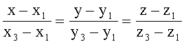

Таким образом, получаем координаты (xo, yo, zo) точки O' - начало координат для координатной системы O'X'Y'Z'.Thus, we obtain the coordinates (x o , y o , z o ) of the point O '- the origin for the coordinate system O'X'Y'Z'.
Далее по двум точкам из множества S4S2S3S1 и точке O' нужно определить направляющие косинусы осей координат системы координат O'X'Y'Z'. Мы условились, что одна из прямых, соединяющих преобразователи, будет осью O'X'. Пусть ось O'X' проходит через точку S1, как и в предыдущих случаях.Next, using two points from the set S 4 S 2 S 3 S 1 and point O ', we need to determine the direction cosines of the coordinate axes of the coordinate system O'X'Y'Z'. We agreed that one of the lines connecting the transducers will be the O'X 'axis. Let the axis O'X 'pass through the point S 1 , as in the previous cases.
Определим длины сторон треугольника O'S1S2:Define the lengths of the sides of the triangle O'S 1 S 2 :
![]()
![]()
![]()
![]()
![]()
![]()
Вектор направляющих косинусов оси О′X′ определяют просто:The vector of the direction cosines of the O′X ′ axis is determined simply:

Определим направляющие косинусы оси O'Y':Define the direction cosines of the O'Y 'axis:

Для этого необходимо определить координаты точки R в системе координат OXYZ. Точка R является проекцией S2 на ось O'Y'.For this, it is necessary to determine the coordinates of the point R in the coordinate system OXYZ. Point R is the projection of S 2 onto the O'Y 'axis.
Прямая RS2 параллельна оси O'X', а значит, их направляющие косинусы совпадают.The straight line RS 2 is parallel to the O'X 'axis, which means that their direction cosines coincide.
Вектор направляющих косинусов прямой RS2 вычисляют как:The vector of the directing cosines of the straight line RS 2 is calculated as:
Поскольку прямая ОХ параллельна RS2, то cosOX=cosRS2, соответственно:Since the direct OH is parallel to RS 2 , then cos OX = cos RS2 , respectively:
(S2-R)/|RS2|=cosO′X′.(S 2 -R) / | RS 2 | = cos O′X ′ .
Откуда получаем координатный вектор точки R:Where do we get the coordinate vector of the point R:
R=S2-|RS2|=cosO′X′.R = S 2 - | RS 2 | = cos O′X ′ .
Отрезок |O'R| определяем из прямоугольного треугольника O′PS2:Line | O'R | determined from the right triangle O′PS 2 :
![]()
![]()
Отрезок |O'P| можно определить следующим образом:Line | O'P | can be defined as follows:
|O'P|=|O′S2|cos(α).| O'P | = | O′S 2 | cos (α).
По теореме косинусов:By the cosine theorem:
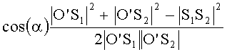
Подставляя данное выражение в предыдущее, получаем:Substituting this expression into the previous one, we get:
Упрощая, получаем:Simplifying, we get:

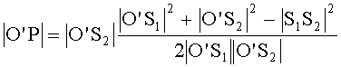
Подставляя полученное выражение для |O'P| в выражение для вычисления значения |O′R|, окончательно получаем длину отрезка O'R:Substituting the resulting expression for | O'P | into the expression for calculating the value of | O′R |, we finally obtain the length of the segment O'R:

Итак, зная значение координат точки R и длину отрезка O'R, получим направляющие косинусы оси O'Y'.So, knowing the value of the coordinates of the point R and the length of the segment O'R, we obtain the direction cosines of the axis O'Y '.
Направляющие косинусы оси O'Z' определяют, исходя из того, что эта ось перпендикулярна к плоскости O'X'Y', а значит, ее направляющие косинусы равны направляющим косинусам нормали к этой плоскости.The direction cosines of the O'Z 'axis are determined based on the fact that this axis is perpendicular to the O'X'Y' plane, which means that its direction cosines are equal to the direction cosines of the normal to this plane.
Зная уравнение плоскости:Knowing the equation of the plane:
A·x+B·y+C·z+D=0,A x + B y + C z + D = 0,
направляющие косинусы нормали вычисляют следующим образом:normal direction cosines are calculated as follows:
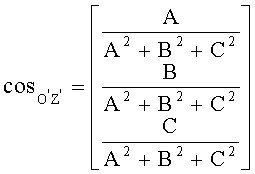
В нашем случае, проще задать уравнение плоскости по 3-м точкам:In our case, it is easier to set the equation of the plane for 3 points:
O'(x0, y0, z0), S1(x1, y1, z1), S2(x2, y2, z2), тогда A, B, C задают следующими определителями:O '(x 0 , y 0 , z 0 ), S 1 (x 1 , y 1 , z 1 ), S 2 (x 2 , y 2 , z 2 ), then A, B, C are defined by the following determinants:
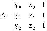
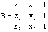

Зная направляющие косинусы всех осей системы координат O'X'Y'Z', можно определить матрицу вращения T для перехода из координатной системы O'X'Y'Z' в OXYZ.Knowing the direction cosines of all the axes of the O'X'Y'Z 'coordinate system, we can determine the rotation matrix T for the transition from the O'X'Y'Z' coordinate system to OXYZ.
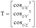
Теперь, используя данную матрицу вращения, мы можем перевести вектор направления на источник сигнала ν' из координатной системы O'X'Y'Z' в OXYZ следующим образом (в матричном виде):Now, using this rotation matrix, we can translate the direction vector to the signal source ν 'from the coordinate system O'X'Y'Z' into OXYZ as follows (in matrix form):
ν(A, E)=TT·ν(A, E)'.ν (A, E) = T T · ν (A, E) '.
После вычисления векторов ![]()
![]()
![]()
![]()
![]()
![]()
Затем координаты найденного таким образом вектора, переводят в сферическую систему координат, связанную с антенной решеткой, с помощью формул:Then the coordinates of the vector found in this way are transferred to a spherical coordinate system associated with the antenna array using the formulas:
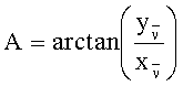
![]()
![]()
где ![]()
![]()
![]()
![]()
![]()
![]()
в результате чего получают значения горизонтального A и вертикального E углов, задающих направление на гидроакустический маяк-ответчик.as a result, the values of the horizontal A and vertical E angles that specify the direction to the sonar beacon responder are obtained.
Заявляемый способ позволяет уменьшить вычислительные затраты на выполнение процедуры определения направления на гидроакустический маяк-ответчик при обработке сигналов, принятых преобразователями антенной решетки.The inventive method allows to reduce the computational cost of the procedure for determining the direction to the sonar beacon-transponder when processing signals received by the transducers of the antenna array.
Claims (1)

где k - аргумент взаимной корреляционной функции, соответствующий сдвигу в отсчетах двух сигналов x1 и x2, изменяющийся в диапазоне - kmax≤k≤kmax;
N - количество отсчетов анализируемого фрагмента сигнала;
и для каждой пары преобразователей вычисляют разность моментов времени прихода плоского фронта волны к преобразователям:
где
затем для каждой плоскости по найденным относительным задержкам для двух пар преобразователей и известным координатам акустических центров преобразователей вычисляют горизонтальный A' и вертикальный E' углы направления на источник сигнала в системе координат O'X'Y'Z' соответствующей плоскости:
где X1=x1-x3 - разность абсцисс акустических центров преобразователей 1 и 3, образующих плоскость;
Х2=x2-x4 - разность абсцисс акустических центров преобразователей 2 и 4;
H1=h1-h3, где h1 и h3 - расстояние, проходимое плоским фронтом волны от преобразователей 1 и 3 до начала системы координат, связанной с рассматриваемой плоскостью;
H2=h2-h3, где h2 и h3 - расстояния, проходимые плоским фронтом волны от преобразователей 2 и 3 до начала системы координат, связанной с рассматриваемой плоскостью;
затем для каждого направления, задаваемого значениями горизонтального и вертикального углов, вычисляют единичный вектор в прямоугольной системе координат, связанной с каждой из плоскостей:
где
и выполняют перевод прямоугольных координат найденных векторов в систему координат, связанную с антенной решеткой, по формуле:
где cosO'X' - направляющий косинус оси O'X' в системе координат OXYZ;
cosO'Y' - направляющий косинус оси O'Y' в системе координат OXYZ;
cosO'Z' - направляющий косинус оси O'Z' в системе координат OXYZ;
после вычисления векторов

где
в результате чего получают значения горизонтального A и вертикального E углов, задающих направление на гидроакустический маяк-ответчик. A method for determining the direction of a hydroacoustic transponder beacon in a horizontal and vertical angle, including emitting a request signal from a ship and receiving a response signal from a transponder beacon by a spatial antenna array, characterized in that the spatial antenna array is divided into a set of planes so that each plane is formed by acoustic the centers of three or four transducers lying on two mutually intersecting straight lines, with each plane connect their rectangular system of coordinates the horizontal and vertical angles of direction to the signal source are calculated and the transducers whose acoustic centers form this plane are divided into two pairs, the signal is digitized with a sampling frequency F s , the mutual correlation function of the signals x 1 and x 2 received by the transducers of each pairs according to the formula:
where k is the argument of the mutual correlation function corresponding to the shift in the samples of two signals x 1 and x 2 , varying in the range - k max ≤k≤k max ;
N is the number of samples of the analyzed fragment of the signal;
and for each pair of transducers calculate the difference in moments of time of arrival of a plane wave front to the transducers:
Where
then, for each plane, based on the found relative delays for two pairs of transducers and the known coordinates of the acoustic centers of the transducers, the horizontal A 'and vertical E' angles of direction to the signal source in the coordinate system O'X'Y'Z 'of the corresponding plane are calculated:
where X 1 = x 1 -x 3 - the difference of the abscissas of the acoustic centers of the transducers 1 and 3, forming a plane;
X 2 = x 2 -x 4 - the difference of the abscissas of the acoustic centers of the transducers 2 and 4;
H 1 = h 1 -h 3 , where h 1 and h 3 - the distance traveled by the plane wave front from the transducers 1 and 3 to the origin of the coordinate system associated with the plane in question;
H 2 = h 2 -h 3 , where h 2 and h 3 are the distances traveled by the plane wave front from transducers 2 and 3 to the origin of the coordinate system associated with the plane in question;
then, for each direction specified by the values of horizontal and vertical angles, a unit vector is calculated in a rectangular coordinate system associated with each of the planes:
Where
and translate the rectangular coordinates of the vectors found into the coordinate system associated with the antenna array, according to the formula:
where cos O'X ' is the direction cosine of the O'X' axis in the OXYZ coordinate system;
cos O'Y ' - the directing cosine of the O'Y' axis in the OXYZ coordinate system;
cos O'Z ' is the direction cosine of the O'Z' axis in the OXYZ coordinate system;
after computing vectors
Where
as a result, the values of the horizontal A and vertical E angles that specify the direction to the sonar beacon responder are obtained.
Priority Applications (1)
| Application Number | Priority Date | Filing Date | Title |
|---|---|---|---|
| RU2011146852/28A RU2492498C2 (en) | 2011-11-17 | 2011-11-17 | Method of determining direction of hydroacoustic transponder beacon on horizontal and vertical angle |
Applications Claiming Priority (1)
| Application Number | Priority Date | Filing Date | Title |
|---|---|---|---|
| RU2011146852/28A RU2492498C2 (en) | 2011-11-17 | 2011-11-17 | Method of determining direction of hydroacoustic transponder beacon on horizontal and vertical angle |
Publications (2)
| Publication Number | Publication Date |
|---|---|
| RU2011146852A RU2011146852A (en) | 2013-05-27 |
| RU2492498C2 true RU2492498C2 (en) | 2013-09-10 |
Family
ID=48789033
Family Applications (1)
| Application Number | Title | Priority Date | Filing Date |
|---|---|---|---|
| RU2011146852/28A RU2492498C2 (en) | 2011-11-17 | 2011-11-17 | Method of determining direction of hydroacoustic transponder beacon on horizontal and vertical angle |
Country Status (1)
| Country | Link |
|---|---|
| RU (1) | RU2492498C2 (en) |
Cited By (1)
| Publication number | Priority date | Publication date | Assignee | Title |
|---|---|---|---|---|
| RU2826224C1 (en) * | 2023-11-24 | 2024-09-06 | Иван Иванович Павлов | Underwater wireless acoustic transceiver |
Families Citing this family (1)
| Publication number | Priority date | Publication date | Assignee | Title |
|---|---|---|---|---|
| CN118534447B (en) * | 2024-07-22 | 2024-10-11 | 蓝海星网装备科技(青岛)有限公司 | Ultra-short baseline ten-array-element acoustic array and positioning method thereof |
Citations (5)
| Publication number | Priority date | Publication date | Assignee | Title |
|---|---|---|---|---|
| US4229809A (en) * | 1979-01-29 | 1980-10-21 | Sperry Corporation | Acoustic under sea position measurement system |
| US4758997A (en) * | 1986-08-25 | 1988-07-19 | Hydroacoustics Inc. | Method and apparatus for the generation and transmission of signals for echo location and other signaling purposes, particularly in geophysical exploration |
| RU2285273C1 (en) * | 2005-04-18 | 2006-10-10 | Государственное образовательное учреждение высшего профессионального образования Военно-морская академия им. Адмирала Флота Советского Союза Н.Г. Кузнецова | Method for using navigational hydro-acoustic system by underwater apparatuses with determining of position by difference between distances to leading underwater device and response beacons |
| RU2292057C1 (en) * | 2005-06-07 | 2007-01-20 | Государственное образовательное учреждение высшего профессионального образования Военно-морская академия им. Адмирала Флота Н.Г. Кузнецова | Mode of using by underwater vehicles of a hydro acoustic system with determination of the location by differences of distances to responder beacons |
| RU2010103076A (en) * | 2010-01-29 | 2011-08-10 | Сергей Борисович Курсин (RU) | METHOD FOR DETERMINING COORDINATES BY MEANS OF A HYDROACOUSTIC NAVIGATION SYSTEM |
-
2011
- 2011-11-17 RU RU2011146852/28A patent/RU2492498C2/en not_active IP Right Cessation
Patent Citations (5)
| Publication number | Priority date | Publication date | Assignee | Title |
|---|---|---|---|---|
| US4229809A (en) * | 1979-01-29 | 1980-10-21 | Sperry Corporation | Acoustic under sea position measurement system |
| US4758997A (en) * | 1986-08-25 | 1988-07-19 | Hydroacoustics Inc. | Method and apparatus for the generation and transmission of signals for echo location and other signaling purposes, particularly in geophysical exploration |
| RU2285273C1 (en) * | 2005-04-18 | 2006-10-10 | Государственное образовательное учреждение высшего профессионального образования Военно-морская академия им. Адмирала Флота Советского Союза Н.Г. Кузнецова | Method for using navigational hydro-acoustic system by underwater apparatuses with determining of position by difference between distances to leading underwater device and response beacons |
| RU2292057C1 (en) * | 2005-06-07 | 2007-01-20 | Государственное образовательное учреждение высшего профессионального образования Военно-морская академия им. Адмирала Флота Н.Г. Кузнецова | Mode of using by underwater vehicles of a hydro acoustic system with determination of the location by differences of distances to responder beacons |
| RU2010103076A (en) * | 2010-01-29 | 2011-08-10 | Сергей Борисович Курсин (RU) | METHOD FOR DETERMINING COORDINATES BY MEANS OF A HYDROACOUSTIC NAVIGATION SYSTEM |
Cited By (1)
| Publication number | Priority date | Publication date | Assignee | Title |
|---|---|---|---|---|
| RU2826224C1 (en) * | 2023-11-24 | 2024-09-06 | Иван Иванович Павлов | Underwater wireless acoustic transceiver |
Also Published As
| Publication number | Publication date |
|---|---|
| RU2011146852A (en) | 2013-05-27 |
Similar Documents
| Publication | Publication Date | Title |
|---|---|---|
| US8107320B2 (en) | Autonomous sonar system and method | |
| RU2515179C1 (en) | Method of determining direction of hydroacoustic transponder in multibeam navigation signal propagation conditions | |
| US20120098703A1 (en) | Method for Determining Azimuth and Elevation Angles of Arrival of Coherent Sources | |
| US5615175A (en) | Passive direction finding device | |
| RU2624449C1 (en) | Method of polarisation deprecition of radiosignals | |
| US11953580B2 (en) | Over the horizon radar (OTH) system and method | |
| CN101581785A (en) | Three-dimensional looking forward sound imaging sonar system for underwater vehicle and using method thereof | |
| JP2020193881A (en) | Azimuth estimating device, azimuth estimating method, and program | |
| RU2557808C1 (en) | Method of determining inclined range to moving target using passive monostatic direction-finder | |
| EP2317335B1 (en) | Improved beamforming method for analysing signals received by a transducer arrray, and relative detection system | |
| Boiko et al. | Design concepts for mobile computing direction finding systems | |
| RU2613369C1 (en) | Method of aircraft navigation using high-precision single-phase direction finder and address-respond packet digital radio link in decameter waves range | |
| RU2711341C1 (en) | Two-dimensional direction finding method | |
| Dzikowicz et al. | Demonstration of spiral wave front sonar for active localization | |
| RU2492498C2 (en) | Method of determining direction of hydroacoustic transponder beacon on horizontal and vertical angle | |
| JP3484995B2 (en) | Instantaneous passive distance measuring device | |
| US20020126043A1 (en) | Method and apparatus for locating a terrestrial transmitter from a satellite | |
| RU2653956C1 (en) | Method of determination of present position data in the bistatic mode of hydrospace detection | |
| US20060083110A1 (en) | Ambient bistatic echo ranging system and method | |
| JP7413850B2 (en) | Angle estimation device and method for object position, and radar device | |
| RU2614035C1 (en) | One-stage method of decameter range radiation sources direction finding using phased antenna array consisting of mutually orthogonal symmetric horizontal dipoles | |
| US7362655B1 (en) | Time-synchronous acoustic signal ranging system and method | |
| RU2405166C2 (en) | Method for determining location of transmitter with portable position finder | |
| RU2195683C2 (en) | Method determining direction on target | |
| CN116736283A (en) | A near-field angle measurement method for wide-area ultra-sparse MIMO radar system |
Legal Events
| Date | Code | Title | Description |
|---|---|---|---|
| MM4A | The patent is invalid due to non-payment of fees |
Effective date: 20141118 |