RU2492429C2 - Measuring device for determining parameter of fluid medium - Google Patents
Measuring device for determining parameter of fluid medium Download PDFInfo
- Publication number
- RU2492429C2 RU2492429C2 RU2010124614/28A RU2010124614A RU2492429C2 RU 2492429 C2 RU2492429 C2 RU 2492429C2 RU 2010124614/28 A RU2010124614/28 A RU 2010124614/28A RU 2010124614 A RU2010124614 A RU 2010124614A RU 2492429 C2 RU2492429 C2 RU 2492429C2
- Authority
- RU
- Russia
- Prior art keywords
- lattice
- flow
- measuring device
- partitions
- forming
- Prior art date
Links
- 239000012530 fluid Substances 0.000 title claims abstract description 53
- 238000005192 partition Methods 0.000 claims abstract description 69
- 238000002485 combustion reaction Methods 0.000 claims description 6
- 230000000694 effects Effects 0.000 abstract description 6
- 239000000126 substance Substances 0.000 abstract description 2
- 238000013461 design Methods 0.000 description 7
- 238000000034 method Methods 0.000 description 5
- 238000002156 mixing Methods 0.000 description 5
- 230000008569 process Effects 0.000 description 5
- 239000007789 gas Substances 0.000 description 3
- 230000001788 irregular Effects 0.000 description 3
- 239000012528 membrane Substances 0.000 description 3
- 230000001413 cellular effect Effects 0.000 description 2
- 239000013078 crystal Substances 0.000 description 2
- 239000012634 fragment Substances 0.000 description 2
- 230000007704 transition Effects 0.000 description 2
- XUIMIQQOPSSXEZ-UHFFFAOYSA-N Silicon Chemical compound [Si] XUIMIQQOPSSXEZ-UHFFFAOYSA-N 0.000 description 1
- 230000009471 action Effects 0.000 description 1
- 230000003197 catalytic effect Effects 0.000 description 1
- 238000001311 chemical methods and process Methods 0.000 description 1
- 238000005516 engineering process Methods 0.000 description 1
- 239000000446 fuel Substances 0.000 description 1
- 238000010438 heat treatment Methods 0.000 description 1
- 230000006872 improvement Effects 0.000 description 1
- 230000004941 influx Effects 0.000 description 1
- 230000002401 inhibitory effect Effects 0.000 description 1
- 238000003780 insertion Methods 0.000 description 1
- 230000037431 insertion Effects 0.000 description 1
- 239000007788 liquid Substances 0.000 description 1
- 238000004519 manufacturing process Methods 0.000 description 1
- 238000005259 measurement Methods 0.000 description 1
- 238000011089 mechanical engineering Methods 0.000 description 1
- 238000006386 neutralization reaction Methods 0.000 description 1
- 238000012545 processing Methods 0.000 description 1
- 229910052710 silicon Inorganic materials 0.000 description 1
- 239000010703 silicon Substances 0.000 description 1
- 230000006641 stabilisation Effects 0.000 description 1
- 238000011105 stabilization Methods 0.000 description 1
Images
Classifications
-
- G—PHYSICS
- G01—MEASURING; TESTING
- G01F—MEASURING VOLUME, VOLUME FLOW, MASS FLOW OR LIQUID LEVEL; METERING BY VOLUME
- G01F15/00—Details of, or accessories for, apparatus of groups G01F1/00 - G01F13/00 insofar as such details or appliances are not adapted to particular types of such apparatus
-
- G—PHYSICS
- G01—MEASURING; TESTING
- G01F—MEASURING VOLUME, VOLUME FLOW, MASS FLOW OR LIQUID LEVEL; METERING BY VOLUME
- G01F1/00—Measuring the volume flow or mass flow of fluid or fluent solid material wherein the fluid passes through a meter in a continuous flow
- G01F1/68—Measuring the volume flow or mass flow of fluid or fluent solid material wherein the fluid passes through a meter in a continuous flow by using thermal effects
- G01F1/684—Structural arrangements; Mounting of elements, e.g. in relation to fluid flow
- G01F1/6842—Structural arrangements; Mounting of elements, e.g. in relation to fluid flow with means for influencing the fluid flow
Landscapes
- Physics & Mathematics (AREA)
- Fluid Mechanics (AREA)
- General Physics & Mathematics (AREA)
- Measuring Volume Flow (AREA)
- Indicating Or Recording The Presence, Absence, Or Direction Of Movement (AREA)
Abstract
Description
Уровень техникиState of the art
Настоящее изобретение относится к устройствам для измерения по меньшей мере одного параметра потока текучей среды, прежде всего движущегося по проточной трубе потока текучей среды, типа тех, которые известны из различных областей техники. Так, в частности, при проведении многих процессов, например, различных технологических процессов, химических процессов или процессов в машиностроении, требуется подача текучих сред, прежде всего газов (например, воздуха), с определенными свойствами (например, температурой, давлением, скоростью потока, массовым расходом, объемным расходом и т.д.). К числу таких процессов относятся прежде всего процессы сгорания, протекающие при регулируемых условиях.The present invention relates to devices for measuring at least one parameter of a fluid flow, in particular a fluid flow moving along a flow pipe, such as those known from various fields of technology. So, in particular, when carrying out many processes, for example, various technological processes, chemical processes or processes in mechanical engineering, it is necessary to supply fluids, primarily gases (for example, air), with certain properties (for example, temperature, pressure, flow rate, mass flow, volume flow, etc.). Among these processes are primarily combustion processes occurring under controlled conditions.
Важным примером практического применения являются процессы сгорания топлива в двигателях внутреннего сгорания (ДВС), которые устанавливаются на автомобили, прежде всего с последующей каталитической нейтрализацией отработавших газов, для чего требуется регулируемая подача определенной массы воздуха в единицу времени (массовый расход воздуха). Для измерения массового расхода воздуха при этом используются датчики различных типов. Одним из известных из уровня техники типов датчиков является пленочный термоанемометрический массовый расходомер воздуха (ПТМРВ), один из вариантов конструктивного исполнения которого описан, например, в DE 19601791 А1. В таких пленочных термоанемометрических массовых расходомерах воздуха обычно используется кристалл с датчиком, имеющий тонкую мембрану, например, кремниевый кристалл с датчиком. На мембране обычно расположен по меньшей мере один нагревательный резистор, который окружен двумя или более термометрами сопротивления (температурными датчиками). В воздушном потоке, проходящем через мембрану, изменяется распределение температур, что в свою очередь может регистрироваться термометрами сопротивления и обрабатываться схемой управления и обработки результатов измерения. Так, например, на основании разности сопротивлений термометров сопротивлений можно определять массовый расход воздуха. Различные другие варианты датчиков этого типа известны из уровня техники. Настоящее изобретение, кроме того, не ограничено датчиками описанного типа, к которому относятся пленочные термоанемометрические массовые расходомеры воздуха, а в принципе может использоваться применительно к датчикам большинства типов, которые используются в виде стационарно смонтированных датчиков или в виде вставных датчиков в потоке текучей среды.An important example of practical application are the processes of fuel combustion in internal combustion engines (ICE), which are installed on cars, primarily with the subsequent catalytic neutralization of exhaust gases, which requires an adjustable supply of a certain mass of air per unit time (mass air flow). To measure the mass air flow, various types of sensors are used. One of the types of sensors known from the prior art is a film hot-wire anemometric mass air flow meter (PTMRV), one of the design options of which is described, for example, in DE 19601791 A1. Such film hot-film air mass flowmeters typically use a crystal with a sensor having a thin membrane, for example, a silicon crystal with a sensor. At least one heating resistor is usually located on the membrane, which is surrounded by two or more resistance thermometers (temperature sensors). The temperature distribution changes in the air flow passing through the membrane, which in turn can be recorded by resistance thermometers and processed by a control and processing circuit for the measurement results. So, for example, based on the difference in resistance of the resistance thermometers, it is possible to determine the mass air flow. Various other sensor variants of this type are known in the art. The present invention, in addition, is not limited to sensors of the described type, which include film hot-film anemometric mass air flow meters, and in principle can be used with most types of sensors, which are used as permanently mounted sensors or as plug-in sensors in a fluid stream.
Однако недостаток описанных в уровне техники конструкций вставных датчиков состоит в том, что известные вставные датчики из-за их аэродинамически неблагоприятной конфигурации во многих случаях создают проблемы во впускном тракте касательно обусловленного аэрогидродинамическим сопротивлением падения давления. Сказанное означает, в частности, что воспроизводимость сигналов подобных датчиков не оптимальна. Многие датчики и прежде всего пленочные термоанемометрические массовые расходомеры воздуха на практике оснащают решеткой или комбинацией решеток. Такие решетки, которые могут быть встроены, например, в проточную трубу, обычно расположены в потоке текучей среды в нескольких сантиметрах перед вставным измерительным преобразователем, соответственно перед датчиком и служат для выравнивания профиля скорости потока в проточной трубе. Назначение подобных решеток состоит далее в устранении возможно возникшего завихрения потока текучей среды. Выравнивающее поток действие решетки достигается благодаря ее тормозящему воздействию на поток. Одновременно с этим возникает турбулентность, в результате которой происходит перемешивание быстро и медленно движущихся частичных потоков текучей среды и которая тем самым способствует выравниванию скорости всего потока текучей среды по всему поперечному сечению трубы. Достигаемый благодаря этому эффект состоит в том, что характеристика датчика (например, взаимосвязь между массой воздуха и выходной частотой или выходным напряжением) становится практически не зависящей от профиля скорости входящего потока воздуха.However, a drawback of the plug-in sensor designs described in the prior art is that the known plug-in sensors, due to their aerodynamically unfavorable configuration, in many cases create problems in the inlet tract regarding the pressure drop caused by the aero-hydrodynamic resistance. The foregoing means, in particular, that the reproducibility of the signals of such sensors is not optimal. Many sensors, and especially film hot-film anemometric mass air flow meters, are equipped in practice with a grating or a combination of gratings. Such gratings, which can be integrated, for example, in a flow pipe, are usually located in the fluid stream a few centimeters in front of the plug-in measuring transducer, respectively in front of the sensor, and serve to equalize the flow velocity profile in the flow pipe. The purpose of such grids is further to eliminate the possible turbulence in the fluid flow. The flow equalizing effect of the grate is achieved due to its inhibitory effect on the flow. At the same time, turbulence occurs, as a result of which mixing of fast and slowly moving partial fluid flows occurs and which thereby helps to equalize the speed of the entire fluid flow over the entire cross section of the pipe. The effect achieved thanks to this is that the characteristic of the sensor (for example, the relationship between the mass of air and the output frequency or output voltage) becomes practically independent of the profile of the velocity of the incoming air flow.
Пример подобного устройства с решеткой известен из DE 19647081 А1. В отличие от известных решеток с равновеликими и равноотстоящими проточными отверстиями или ячейками эту известную из указанной публикации решетку предлагается выполнять с проточными отверстиями разного проходного сечения. Проходные сечения проточных отверстий решетки при этом согласованы с притоком текучей среды с целью создать по ходу потока после решетки поток с в основном равномерным распределением скорости.An example of such a device with a grid is known from DE 19647081 A1. In contrast to the known gratings with equal and equally spaced flow openings or cells, it is proposed to perform this grating known from the publication with flow openings of different flow cross sections. The cross sections of the flow openings of the grate are aligned with the influx of fluid in order to create a flow with a substantially uniform velocity distribution along the flow after the grate.
Однако у многих датчиков, используемых в сочетании с обычными решетками, таких, например, как массовые расходомеры воздуха с обычными пластмассовыми решетками с размером ячеек от 4 до 7 мм и глубиной ячеек от 5 до 10 мм, в некоторых диапазонах значений массового расхода воздуха следует ожидать сравнительно неудовлетворительной воспроизводимости характеристик. Возможная причина этого заключается в неконтролируемом переходе одной формы течения в другую, т.е. в переходе ламинарного движения в турбулентное, в пределах пограничного слоя у стенки трубы. Пограничный слой у стенки трубы при своем прохождении через решетку типа той, которая используется в большинстве датчиков, обычно становится недостаточно турбулентным, поскольку такая решетка, как правило, по технологическим причинам имеет вблизи стенки более крупные ячейки, чем в центре трубы. Решетка известной из DE 19647081 А1 конструкции с меньшим размером ячеек в краевой зоне предполагает возможность ее дальнейшего усовершенствования, прежде всего усовершенствования, позволяющего улучшить воспроизводимость характеристик датчиков.However, many sensors used in combination with conventional grilles, such as, for example, mass air flow meters with conventional plastic grilles with a cell size of 4 to 7 mm and a cell depth of 5 to 10 mm, can be expected in some ranges of mass air flow comparatively unsatisfactory reproducibility of characteristics. A possible reason for this is the uncontrolled transition of one form of flow to another, i.e. in the transition of laminar motion to turbulent, within the boundary layer at the pipe wall. The boundary layer near the pipe wall, when passing through a grating such as that used in most sensors, usually becomes not sufficiently turbulent, because such a grating, for technological reasons, usually has larger cells near the wall than in the center of the pipe. The lattice of the design known from DE 19647081 A1 with a smaller cell size in the marginal zone suggests the possibility of its further improvement, first of all, to improve the reproducibility of the characteristics of the sensors.
Краткое изложение сущности изобретенияSummary of the invention
В соответствии с этим в изобретении предлагается измерительное устройство для определения по меньшей мере одного параметра движущегося в основном направлении потока текучей среды, прежде всего движущегося по проточной трубе потока впускаемого в двигатель внутреннего сгорания воздуха. В изобретении предлагается далее проточно-трубчатый модуль для применения в подобном измерительном устройстве. Конструктивное исполнение предлагаемых в изобретении измерительного устройства и проточно-трубчатого модуля позволяет по меньшей мере практически полностью устранить описанные выше недостатки, присущие известным измерительным устройствам, соответственно проточно-трубчатым модулям.Accordingly, the invention provides a measuring device for determining at least one parameter of a fluid moving in the main direction, in particular a flow of air admitted into the internal combustion engine, moving through a flow pipe. The invention further provides a flow-tube module for use in such a measuring device. The design of the inventive measuring device and flow-tube module allows at least almost completely eliminate the above-described disadvantages inherent in known measuring devices, respectively, flow-tube modules.
Предлагаемое в изобретении измерительное устройство может быть рассчитано на определение одного или нескольких физических и/или химических параметров текучей среды. В качестве примера таких параметров можно назвать указанные в начале описания параметры. Однако возможно измерение и иных параметров текучей среды. Предлагаемое в изобретении измерительное устройство имеет по меньшей мере один расположенный в потоке текучей среды датчик, способный измерять эти параметры. Без ограничения возможных иных вариантов осуществления изобретения в последующем предполагается, что датчик представляет собой пленочный термоанемометрический массовый расходомер воздуха, такой, например, как известный из указанного выше уровня техники.Proposed in the invention, the measuring device can be designed to determine one or more physical and / or chemical parameters of the fluid. As an example of such parameters, we can mention the parameters indicated at the beginning of the description. However, it is possible to measure other fluid parameters. Proposed in the invention, the measuring device has at least one sensor located in the fluid stream, capable of measuring these parameters. Without limiting the possible other embodiments of the invention, it is further assumed that the sensor is a film hot-wire air mass flow meter, such as, for example, known from the aforementioned prior art.
Текучая среда может представлять собой, например, газ и/или жидкость. Под "основным направлением потока" при этом подразумевается локальное направление потока текучей среды по месту расположения датчика, соответственно всего измерительного устройства, при этом наличие локальных неравномерностей потока (например, наличие турбулентностей) может не учитываться. Тем самым под основным направлением потока текучей среды прежде всего может подразумеваться локальное усредненное направление перемещения потока текучей среды.The fluid may be, for example, gas and / or liquid. In this case, the "main flow direction" means the local direction of the fluid flow at the location of the sensor, respectively, of the entire measuring device, while the presence of local flow irregularities (for example, the presence of turbulences) can be ignored. Thus, the main direction of the fluid flow can primarily be understood as the local averaged direction of movement of the fluid flow.
Предлагаемое в изобретении измерительное устройство имеет далее по меньшей мере одну расположенную поперечно основному направлению потока перед датчиком решетку с образующими ее перегородками. Такие образующие решетку перегородки могут быть выполнены, например, в виде стержней с круглым, овальным или многоугольным поперечным сечением. Особенно предпочтительно, однако, придавать образующим решетку перегородкам уплощенную форму с узкой стороной, обращенной навстречу основному направлению потока, и с продольной протяженностью по существу в основном направлении потока, при этом образующие решетку перегородки можно также (см. ниже) располагать наклонно под углом к основному направлению потока. Указанной продольной протяженностью образующих решетку перегородок вдоль основного направления потока может определяться, например, толщина решетки.The measuring device according to the invention further has at least one grating arranged transversely to the main flow direction in front of the sensor and having partitions forming it. Such lattice-forming partitions can be made, for example, in the form of rods with a round, oval or polygonal cross section. However, it is particularly preferable to give the lattice-forming partitions a flattened shape with a narrow side facing the main flow direction and with a longitudinal extension essentially in the main flow direction, while the lattice-forming partitions can also be arranged (see below) obliquely to the main flow direction. The indicated longitudinal extent of the partitions forming the lattice along the main direction of flow can be determined, for example, the thickness of the lattice.
Основная идея настоящего изобретения заключается в том, что для достижения эффективного действия решетки по выравниванию профиля скорости потока важное значение имеет равномерное создание турбулентностей вплоть до краевых зон проточной трубы с целью положительного влияния на поток и в этих зонах. Для этого решетку предлагается выполнять состоящей из по меньшей мере двух частей и предусматривать по меньшей мере одну первую часть решетки и по меньшей мере одну ее вторую часть. В отличие, например, от DE 19647081 А1 в первой части решетки образующие ее перегородки должны проходить в основном радиально. Выражение "в основном радиально" в данном контексте означает, что образующие решетку перегородки в основном направлении своей протяженности должны располагаться в основном на воображаемой оси, проходящей через ось проточной трубы (которая может иметь, например, круглое или многоугольное поперечное сечение). При этом, однако, в расположении образующих решетку перегородок возможны также отклонения от такой их строго радиальной ориентации, которые должны рассматриваться как подпадающие под понятие "в основном радиально" и которые составляют, например, до 50°, предпочтительно не более 45°, особенно предпочтительно не более 20°.The main idea of the present invention is that in order to achieve the effective action of the lattice in aligning the flow velocity profile, it is important to uniformly create turbulences up to the edge zones of the flow pipe in order to positively influence the flow in these zones as well. For this, it is proposed that the lattice be made up of at least two parts and that at least one first part of the lattice and at least one second part thereof be provided. In contrast, for example, from DE 19647081 A1, in the first part of the lattice, the partitions forming it must pass mainly radially. The expression "mainly radial" in this context means that the partitions forming the lattice in the main direction of their length should be located mainly on an imaginary axis passing through the axis of the flow pipe (which may have, for example, a circular or polygonal cross section). However, in the arrangement of the partitions forming the lattice, deviations from their strictly radial orientation are also possible, which should be considered as falling into the concept of "mainly radial" and which are, for example, up to 50 °, preferably not more than 45 °, particularly preferably no more than 20 °.
Во второй же части решетки образующие ее перегородки должны проходить в основном по секущим. Выражение "в основном по секущим" при этом означает, что образующие решетку перегородки в этой части решетки должны располагаться на секущих к воображаемым окружностям с центрами, лежащими на оси проточной трубы.In the second part of the lattice, the partitions forming it should pass mainly along the secants. The expression "mainly in secants" in this case means that the partitions forming the lattice in this part of the lattice should be located on secants to imaginary circles with centers lying on the axis of the flow pipe.
Подобное измерительное устройство с решеткой вышеописанного типа, подразделенной на две части, позволяет целенаправленно в определенных зонах, которые на практике зарекомендовали себя как проблематичные касательно характера движения в них потока текучей среды, улучшить перемешивание частичных потоков текучей среды. Благодаря этому можно, например, в зоне пограничного слоя у стенки проточной трубы обеспечить постоянно надежное перемешивание, что, например, позволяет во всех рабочих условиях поддерживать турбулентный характер потока. В результате поток за решеткой приобретает более стабильный характер, вследствие чего повышается и воспроизводимость характеристик измерительного устройства. Тем самым появляется возможность отказаться от применения необходимой в противном случае при определенных условиях дополнительной проволочной сетки, снизив благодаря этому стоимость изготовления измерительного устройства. Помимо этого благодаря стабилизации потока удается значительно уменьшить уровень шума в сигнале измерительного устройства.Such a measuring device with a lattice of the type described above, divided into two parts, allows purposefully in certain areas, which in practice have proved to be problematic regarding the nature of the movement of fluid flow in them, to improve the mixing of partial fluid flows. Due to this, it is possible, for example, in the zone of the boundary layer near the wall of the flow pipe to ensure constantly reliable mixing, which, for example, allows you to maintain the turbulent nature of the flow in all operating conditions. As a result, the flow behind the grate becomes more stable, as a result of which the reproducibility of the characteristics of the measuring device increases. Thus, it becomes possible to abandon the use of an additional wire mesh otherwise necessary under certain conditions, thereby reducing the manufacturing cost of the measuring device. In addition, due to the stabilization of the flow, it is possible to significantly reduce the noise level in the signal of the measuring device.
Особенно предпочтительно при этом, чтобы первая часть решетки кольцом охватывала ее вторую часть. Этот вариант осуществления изобретения позволяет целенаправленно в краевой зоне решетки, которая, например, в целом может быть выполнена круглой, достичь описанного выше эффекта перемешивания, обеспечив возможность надежного перемешивания пограничного слоя у стенки проточной трубы. Вторая часть решетки может иметь, например, в основном круглую форму при выполнении первой части решетки, например, в основном в форме кругового кольца. Однако обе части решетки можно также выполнять отличной от круглой формы, например, овальной или многоугольной формы.In this case, it is particularly preferred that the first part of the grating ring enclose its second part. This embodiment of the invention allows purposefully in the edge zone of the lattice, which, for example, can generally be made round, to achieve the mixing effect described above, making it possible to reliably mix the boundary layer near the wall of the flow pipe. The second part of the lattice can, for example, have a substantially circular shape when the first part of the lattice is made, for example, mainly in the form of a circular ring. However, both parts of the lattice can also be made different from a round shape, for example, oval or polygonal.
Как уже указывалось выше, особенно предпочтительной формой образующих решетку перегородок является уплощенная или плоская форма. Так, образующим решеткам перегородкам придана форма, при которой они во второй части решетки аналогично, например, описанной в DE 19647081 А1 решетке имеют поверхности, ориентированные в основном параллельно основному направлению потока. Под выражением "в основном параллельно" при этом может подразумеваться ориентация параллельно основному направлению потока. Однако возможны также небольшие отклонения от такой параллельности, например, отклонения, не превышающие 20°, предпочтительно не превышающие 5°. В отличие от второй части решетки, в ее первой части наряду с образующими решетку перегородками, поверхности которых ориентированы в основном параллельно основному направлению потока, также используются образующие решетку перегородки, которые имеют поверхности с ориентацией, сообщающей потоку текучей среды составляющую скорости, перпендикулярную основному направлению потока. Для этого, например, образующие решетку перегородки по меньшей мере в первой части решетки можно расположить, если смотреть в сечении плоскостью, параллельной основному направлению потока, под углом наклона к основному направлению потока. Благодаря подобному наклонному расположению образующих решетку перегородок потоку текучей среды при его набегании на решетку сообщается составляющая скорости, перпендикулярная основному направлению потока. Указанный угол наклона образующих решетку перегородок может, например, составлять от 5 до 60°, особенно предпочтительно от 10 до 40°. Однако возможны и другие значения угла наклона образующих решетку перегородок. Благодаря обеспечиваемой таким путем закрутке или завихрению потока текучей среды в его радиально внешней зоне за первой частью решетки, например, между радиально внутренней и внешней зонами потока текучей среды может образовываться крайне нестабильный промежуточный слой, который обычно сразу же приводит к возникновению турбулентностей. В результате этого пограничный слой у стенки трубы становится турбулентным, и между медленным потоком текучей среды, движущимся вблизи стенки, и быстрым потоком текучей средой, движущимся в центре проточной трубы, происходит более интенсивный обмен импульсами. Направление, в котором решетка закручивает поток текучей среды, исходно может быть любым, поскольку требуемый эффект может создаваться право - либо левовращающей решеткой.As already indicated above, a particularly preferred shape of the lattice-forming partitions is a flattened or flat shape. Thus, the partitions forming the gratings are given a shape in which they in the second part of the grating, similarly to, for example, the grating described in DE 19647081 A1, have surfaces oriented mainly parallel to the main flow direction. The expression "mainly in parallel" may mean orientation parallel to the main direction of flow. However, small deviations from such parallelism are also possible, for example, deviations not exceeding 20 °, preferably not exceeding 5 °. Unlike the second part of the lattice, in its first part, along with the partitions forming the lattice, the surfaces of which are oriented mainly parallel to the main flow direction, the partitions forming the lattice are also used, which have surfaces with an orientation that imparts a velocity component perpendicular to the main flow direction to the fluid flow . For this, for example, the grating partitions in at least the first part of the grating can be positioned when viewed in cross-section by a plane parallel to the main flow direction, at an angle of inclination to the main flow direction. Due to such an inclined arrangement of the lattice-forming partitions, a fluid component is communicated to the flow of the fluid when it runs onto the lattice, perpendicular to the main flow direction. The specified angle of inclination of the lattice-forming partitions may, for example, be from 5 to 60 °, particularly preferably from 10 to 40 °. However, other values of the angle of inclination of the lattice-forming partitions are possible. Due to the swirling or swirling of the fluid flow in this way in its radially outer zone behind the first part of the grating, for example, an extremely unstable intermediate layer can form between the radially inner and outer zones of the fluid flow, which usually immediately leads to turbulence. As a result of this, the boundary layer near the pipe wall becomes turbulent, and between the slow fluid flow moving near the wall and the fast fluid flow moving in the center of the flow pipe, a more intense exchange of pulses occurs. The direction in which the lattice swirls the fluid flow can initially be any, since the required effect can be created by the right or left-handed lattice.
Угол наклона образующих решетку перегородок может варьироваться в пределах первой части решетки. Особенно предпочтительно, однако, чтобы угол наклона всех образующих решетку перегородок в этой первой части решетки был в основном одинаков (при этом и в данном случае возможны отклонения, например, отклонения в пределах не более 5°). Благодаря подобному однообразному углу наклона всех образующих решетку перегородок в первой части решетки вследствие их радиального расположения потоку текучей среды в зоне за первой частью решетки сообщается завихрение. При расположении первой части решетки кольцом охватывающей ее вторую часть, например, первая часть решетки может обладать в основном однообразным правовращающим или левовращающим свойством для сообщения потоку текучей среды завихрения вправо (т.е. завихрения по часовой стрелке при движении в основном направлении потока) либо завихрения влево (т.е. завихрения против часовой стрелки при движении в основном направлении потока). Благодаря такому целенаправленному завихрению потока в краевой зоне у стенки проточной трубы, но не в ее центральной зоне, дополнительно повышается эффективность перемешивания в этой краевой зоне.The angle of inclination of the partitions forming the grating may vary within the first part of the grating. It is especially preferred, however, that the angle of inclination of all the partitions forming the lattice in this first part of the lattice is basically the same (in this case, deviations are possible, for example, deviations within no more than 5 °). Due to a similar uniform angle of inclination of all the partitions forming the lattice in the first part of the lattice due to their radial arrangement, a turbulence is reported to the fluid flow in the area behind the first part of the lattice. When the first part of the lattice is arranged with a ring enclosing the second part, for example, the first part of the lattice can have basically the same right-handed or left-handed property to impart a swirl to the right of the fluid flow (i.e., swirl clockwise when moving in the main flow direction) or swirl to the left (i.e., counterclockwise swirls when moving in the main flow direction). Due to this purposeful swirling of the flow in the boundary zone near the wall of the flow pipe, but not in its central zone, the mixing efficiency in this boundary zone is further increased.
Образующие решетку перегородки во второй части решетки могут представлять собой перегородки одного или нескольких типов. Так, например, все образующие решетку перегородки в этой части решетки могут быть ориентированы параллельно. Особенно предпочтительно, однако, чтобы аналогично известной из DE 19647081 А1 решетке образующие решетку перегородки в этой второй части решетки образовывали несколько типов взаимно пересекающихся образующих решетку перегородок. Так, например, образующие решетку перегородки первого типа могут быть ориентированы в первом направлении, а образующие решетку перегородки второго типа - во втором направлении, отличном от первого направления. В результате образующие решетку перегородки обоих типов пересекаются между собой, образуя ячеистую решетку. Особенно предпочтительно при этом, поскольку таким путем удается избежать преимущественных направлений, чтобы ячеистая решетка представляла собой решетку с квадратными ячейками, например, ячеистую решетку с размером ячеек (соответствующем длине кромки отверстий или ячеек) от 3 до 7 мм и с глубиной ячеек, например, от 5 до 10 мм.The partitions forming the lattice in the second part of the lattice can be partitions of one or several types. So, for example, all the partitions forming the lattice in this part of the lattice can be oriented in parallel. It is particularly preferred, however, that, similarly to the lattice known from DE 19647081 A1, the lattice-forming partitions in this second part of the lattice form several types of mutually intersecting lattice-forming partitions. So, for example, the lattice-forming partitions of the first type can be oriented in the first direction, and the lattice-forming partitions of the second type can be oriented in the second direction, different from the first direction. As a result, the lattice-forming partitions of both types intersect each other, forming a cellular lattice. In this case, it is particularly preferable, since in this way it is possible to avoid the advantageous directions so that the mesh lattice is a square mesh grid, for example, a mesh grid with a cell size (corresponding to the length of the edge of the holes or cells) from 3 to 7 mm and with a cell depth, for example, from 5 to 10 mm.
Датчик может быть постоянно или стационарно установлен в измерительном устройстве и может иметь, например, консольную измерительную головку, выступающую в поток текучей среды. Однако альтернативно этому или дополнительно к этому датчик может быть также выполнен сменным, например, в виде вставного датчика, помещаемого в поток текучей среды. В соответствии с этим измерительное устройство можно также изготавливать и/или поставлять в виде узла без датчика. Подобный узел ниже обозначается как проточно-трубчатый модуль. Такой проточно-трубчатый модуль, предназначенный для применения в измерительном устройстве, выполненном по одному или нескольким рассмотренным выше вариантам, может иметь прежде всего по меньшей мере один корпус с по меньшей мере одним креплением для размещения датчика, предназначенного для определения по меньшей мере одного параметра движущегося по этому проточно-трубчатому модулю потока текучей среды. Указанное крепление может, например, представлять собой отверстие в корпусе, через которое в поток текучей среды можно вставить консольную измерительную головку датчика. Для крепления датчика могут быть предусмотрены также штуцер, фланец или крепежные элементы иных аналогичных типов.The sensor may be permanently or permanently mounted in the measuring device and may have, for example, a cantilever measuring head protruding into the fluid stream. However, an alternative to this or in addition to this, the sensor can also be made replaceable, for example, in the form of an insertion sensor placed in a fluid stream. Accordingly, the measuring device can also be manufactured and / or delivered as an assembly without a sensor. A similar assembly is referred to below as a flow-tube module. Such a flow-tube module, intended for use in a measuring device made according to one or more of the above options, may have at least one housing with at least one mount to accommodate a sensor for detecting at least one moving parameter along this flow-tubular fluid flow module. Said mount may, for example, be an opening in the housing through which a cantilever measuring head of the sensor can be inserted into the fluid stream. A fitting, flange or other similar types of fasteners may also be provided for mounting the sensor.
Проточно-трубчатый модуль имеет далее по меньшей мере одну решетку, выполненную по одному из рассмотренных выше вариантов, т.е. решетку с по меньшей мере одной первой частью с радиальным расположением образующих решетку перегородок и с по меньшей мере одной второй частью с расположением образующих решетку перегородок на секущих.The flow-tube module further has at least one grate made according to one of the above options, i.e. a lattice with at least one first part with a radial arrangement of the lattice-forming partitions and with at least one second part with an arrangement of the lattice-forming partitions on the secant.
Краткое описание чертежейBrief Description of the Drawings
Ниже изобретение более подробно рассмотрено на примере некоторых вариантов его осуществления со ссылкой на прилагаемые к описанию чертежи, на которых показано:Below the invention is described in more detail on the example of some variants of its implementation with reference to the accompanying drawings, which show:
на фиг.1 и 2 - различные виды в аксонометрии выполненного по одному из вариантов измерительного устройства, известного из уровня техники,figure 1 and 2 are various views in a perspective view made according to one of the variants of the measuring device known from the prior art,
на фиг.3 - вид в плане решетки, выполненной по одному из предлагаемых в изобретении вариантов,figure 3 is a view in plan of the lattice made according to one of the proposed invention,
на фиг.4 - вид в разрезе фрагмента решетки с наклонным расположением образующих ее перегородок, иfigure 4 is a view in section of a fragment of the lattice with an inclined arrangement of the partitions forming it, and
на фиг.5 - вид в плане решетки с наклонным расположением образующих ее перегородок.figure 5 is a view in plan of the lattice with an inclined arrangement of the partitions forming it.
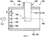
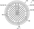
На фиг.1 и 2 в разных видах показано выполненное по одному из вариантов измерительное устройство 110, известное из уровня техники. При этом на фиг.1 измерительное устройство 110 показано в разрезе плоскостью, параллельной основному направлению 112 потока текучей среды, а на фиг.2 - в виде в плане с направления, соответствующего основному направлению 112 потока.Figure 1 and 2 in different views shows made according to one of the variants of the measuring
Измерительное устройство 110 имеет датчик 114, который в данном варианте выполнен в виде пленочного термоанемометрического массового расходомера 116 воздуха. Такой пленочный термоанемометрический массовый расходомер 116 воздуха имеет консольную измерительную головку 118 с впускным отверстием 120, которое расположено примерно по центру в проточной трубе 122 измерительного устройства 110. Конструктивное исполнение пленочного термоанемометрического массового расходомера 116 воздуха может соответствовать, например, одному из известных из уровня техники вариантов его конструктивного исполнения, в частности описанному в DE 19647981 А1 устройству.The measuring
Наряду с датчиком 114 измерительное устройство 110 имеет проточно-трубчатый модуль 124. Такой проточно-трубчатый модуль 124 имеет корпус 126, который в зоне измерительного устройства 110 образует проточную трубу 122. С этой целью корпус 126 может быть снабжен, например, соответствующими соединительными патрубками для применения, например, во впускном тракте ДВС. Помимо этого могут быть предусмотрены крепежные элементы, такие, например, как фланцы, канавки, выступы и т.д., известные специалистам в данной области из уровня техники.Along with the sensor 114, the measuring
Корпус 126 имеет далее крепление 128 для датчика 114. Такое крепление 128 имеет отверстие 130, а также надставку 132. Отверстие 130 и надставка 132 имеют такие размеры, что консольную измерительную головку 118 датчика 114 можно вставить в отверстие 130 в основном по точно пригнанной посадке и зафиксировать в надставке 132.The housing 126 further has a
Проточно-трубчатый модуль 124 измерительного устройства 110 имеет далее расположенную в основном направлении 112 потока перед впускным отверстием 120 решетку 134. Такая решетка 134 расположена в основном поперечно основному направлению 112 потока, предпочтительно перпендикулярно основному направлению 112 потока, при этом, однако, возможны также отклонения от подобной ортогональности. Решетка 134 имеет толщину D, измеряемую в основном направлении 112 потока и составляющую обычно от 5 до 10 мм. Решетка 134 имеет далее множество образующих ее перегородок 136, которые в поперечном сечении имеют плоскую форму и узкая сторона которых тем самым обращена навстречу основному направлению 112 потока. Как показано на фиг.1, образующие решетку перегородки 136 могут иметь в поперечном сечении, например, слегка клиновидную форму. Помимо этого образующие решетку перегородки могут иметь и иной профиль в поперечном сечении, например, форму крыла (несущей поверхности), прямоугольную форму, овальную форму или аналогичную форму.The flow-
Как показано в виде в плане на фиг.2, решетка в данном варианте, которая соответствует, например, имеющемуся в продаже пленочному термоанемометрическому массовому расходомеру воздуха типа "HFM7" фирмы Robert Bosch GmbH, выполнена в виде решетки с квадратными ячейками. Сказанное означает, что образующие решетку перегородки 136 первого типа 138 расположены в основном параллельно друг другу и перпендикулярно образующим решетку перегородкам 136 второго типа 140, которые между собой в свою очередь также расположены параллельно друг другу. У образующейся в результате решетки ее ячейки имеют размер (соответствующей длине стороны квадратов), который обычно составляет от 4 до 7 мм. Согласно изобретению было установлено, что искажения проточных свойств измерительного устройства 110, показанного на фиг.1 и 2, возникают прежде всего из-за наличия нерегулярной структуры решетки 134 в ее краевой зоне. Такая нерегулярная структура решетки обозначена на фиг.2 позицией 142 и обусловлена главным образом тем, что ячейки в этой зоне по технологическим причинам имеют большую ширину, чем в центре проточной трубы 122.As shown in the plan view in FIG. 2, the grill in this embodiment, which corresponds, for example, to a commercially available film hot-film air mass meter type “HFM7” from Robert Bosch GmbH, is made in the form of a grid with square cells. The aforesaid means that the lattice-forming
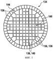
На фиг.3-5 показана решетка 134, выполненная по предлагаемым в изобретении вариантам, позволяющим согласно изобретению модифицировать показанное, например, на фиг.1 и 2 измерительное устройство 110.Figure 3-5 shows the
На фиг.3 в виде в плане с направления, соответствующего основному направлению 112 потока, показана выполненная по первому варианту предлагаемая в изобретении решетка 134. Как показано на чертеже, решетка 134, как и у показанного на фиг.2 измерительного устройства, выполнена в виде круглой решетки, что, однако, не является строго обязательным. Решетка 134 имеет первую часть 144, которая в виде кругового кольца охватывает вторую часть 146 решетки, представляющую собой ее центральную часть, расположенную вокруг оси 148 измерительного устройства (см. фиг.1).Figure 3 in a plan view from the direction corresponding to the main direction of
Вторая часть 146 решетки при этом также выполнена в виде ячеистой решетки, например, аналогично решетке 134, показанной на фиг.2. Речь при этом также идет о решетке с квадратными ячейками.The
Вокруг этой второй части 146 решетки расположена имеющая форму кругового кольца ее первая часть 144, в которой образующие решетку перегородки 136 расположены радиально. Такие образующие решетку перегородки 136 с радиальным их расположением могут быть равномерно распределены по окружности. В другом варианте радиальные образующие решетку перегородки 136 могут также располагаться в первой части 144 решетки, гранича непосредственно с нерегулярной структурой 142 решетки в краевой зоне ее второй части 146. Возможны и иные схемы расположения образующих решетку радиальных перегородок 136 в первой части 144 решетки.Around this
Образующие решетку перегородки 136 в ее первой части 144 могут быть выполнены такой же толщины, что и образующие решетку перегородки 136 в ее второй части 146. В другом варианте, однако, эти образующие решетку перегородки 136 могут также иметь иное исполнение касательно их размеров и/или их формы и/или их прочих характеристик. В общем случае во второй части 146 решетки 134 ее ячейки предпочтительно выполнять размером от 3 до 7 мм при толщине D решетки (см. фиг.1) примерно от 5 до 10 мм. Однако решетку можно выполнять и с другими размерами.The lattice-forming
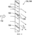
В показанных на фиг.1 и 3 вариантах выполнения решеток 134 образующие их перегородки 136 своими поверхностями 159 проходят в основном параллельно основному направлению 112 потока. Однако такое расположение образующих решетку перегородок не является строго обязательным. Тем не менее предпочтительно, чтобы поверхности 150 образующих решетку перегородок во второй части 146 решетки проходили, как и ранее, параллельно основному направлению 112 потока. В первой же части 144 решетки возможна также ориентация поверхностей 150 образующих решетку перегородок наклонно к основному направлению 112 потока под углом а. Вариант выполнения решетки 134 с подобным наклонным расположением образующих ее перегородок схематично показан на фиг.4 и 5. При этом на фиг.4 в разрезе показан фрагмент первой части 144 решетки, а на фиг.5 решетка показана в виде в плане аналогично виду, приведенному на фиг.3.In the
Как показано на фиг.4, благодаря наклонному расположению поверхностей 150 образующих решетку перегородок к основному направлению 112 потока под углом а поток текучей среды, условно показанные на фиг.4 линии которого обозначены позицией 152, приобретает составляющую скорости, перпендикулярную основному направлению 112 потока. В этом отношении образующие решетку перегородки в первой части 144 решетки создают эффект, аналогичный эффекту пропеллера.As shown in FIG. 4, due to the oblique arrangement of the
При расположении всех образующих решетку перегородок 136 в первой части 144 решетки с одинаковым углом наклона а поток текучей среды за первой частью 144 решетки, т.е. в краевой зоне проточной трубы 122, завихряется или закручивается. В зависимости от того, движется ли текучая среда, если смотреть с направления, соответствующего основному направлению 112 потока, против часовой стрелки или по часовой стрелке, можно говорить о наличии у первой части 144 решетки "левовращающего" или "правовращающего" свойства. В результате завихрения или закрутки потока текучей среды в радиально внешней зоне между радиально внутренней и радиально внешней зонами потока текучей среды образуется крайне нестабильный промежуточный (сдвиговый) слой, который непосредственно приводит к возникновению турбулентности. Сказанное проиллюстрировано на фиг.5 на примере левовращающей решетки 134. Образующие решетку перегородки 136 ориентированы при этом наклонно к основному направлению 112 потока под углом а, например, аналогично показанному на фиг.4 варианту. Углы наклона при этом одинаковы для всех образующих решетку перегородок 136, и поэтому, например, образующая решетку перегородка, находящаяся на фиг.5 в положении на 9 часов, при ее рассматривании с направления, соответствующего основному направлению 112 потока, наклонена вниз, тогда как образующая решетку перегородка, находящаяся на фиг.5 в положении на 3 часа, наклонена вверх. Соответственно в показанном на фиг.5 варианте речь идет о левовращающей решетке. Такая левовращающая решетка сообщает пограничному слою у стенки вращательный импульс.With the arrangement of all the lattice-forming
Промежуточный слой между радиально внутренней и радиально внешней зонами потока текучей среды за первой частью 144 решетки и ее второй частью 146 условно показан на фиг.5 и обозначен позицией 154. Такой промежуточный слой 154, который сразу же приводит к возникновению турбулентности, приводит к тому, что пограничный слой у стенки также становится турбулентным и что между потоком текучей среды, движущимся вблизи стенки, и быстрым потоком текучей средой, движущимся в центре трубы, происходит более интенсивный обмен импульсами. Очевидно, однако, что решетку 134 можно также выполнить закручивающей или завихряющей поток текучей среды в противоположном направлении.The intermediate layer between the radially internal and radially external zones of the fluid flow behind the
Claims (11)
Applications Claiming Priority (3)
| Application Number | Priority Date | Filing Date | Title |
|---|---|---|---|
| DE102007055193.4 | 2007-11-19 | ||
| DE102007055193A DE102007055193A1 (en) | 2007-11-19 | 2007-11-19 | Sensor arrangement for determining a parameter of a fluid medium |
| PCT/EP2008/064090 WO2009065680A1 (en) | 2007-11-19 | 2008-10-20 | Sensor arrangement for determining a parameter of a fluid medium |
Publications (2)
| Publication Number | Publication Date |
|---|---|
| RU2010124614A RU2010124614A (en) | 2011-12-27 |
| RU2492429C2 true RU2492429C2 (en) | 2013-09-10 |
Family
ID=40419015
Family Applications (1)
| Application Number | Title | Priority Date | Filing Date |
|---|---|---|---|
| RU2010124614/28A RU2492429C2 (en) | 2007-11-19 | 2008-10-20 | Measuring device for determining parameter of fluid medium |
Country Status (5)
| Country | Link |
|---|---|
| EP (1) | EP2215433B1 (en) |
| CN (1) | CN101868697B (en) |
| DE (1) | DE102007055193A1 (en) |
| RU (1) | RU2492429C2 (en) |
| WO (1) | WO2009065680A1 (en) |
Families Citing this family (10)
| Publication number | Priority date | Publication date | Assignee | Title |
|---|---|---|---|---|
| DE102009054622A1 (en) | 2009-12-14 | 2015-08-06 | Robert Bosch Gmbh | flow grille |
| DE102010062891A1 (en) | 2010-12-13 | 2012-06-14 | Robert Bosch Gmbh | Flow grid of sensor arrangement for determining intake air mass of combustion engine, has grid cell with fluid medium guide surface extended over entire cross-section of flow tube while generating vortices along fluid medium flow |
| DE102010062892B4 (en) | 2010-12-13 | 2023-07-06 | Robert Bosch Gmbh | Flow grid for use in a flow tube of a flowing fluid medium |
| DE102011105441B3 (en) * | 2011-06-20 | 2012-07-26 | Mann + Hummel Gmbh | Flow grid for equalizing air stream in flow channel, has two meander-shaped strips, where strips have multiple legs, where belts are arranged in flow direction of air stream behind each other and relative to legs offset from each other |
| DE102011078992A1 (en) | 2011-07-12 | 2013-01-17 | Robert Bosch Gmbh | Sensor arrangement i.e. hot-film air mass gauge, for determination of flow property of intake air of internal combustion engine in motor car, has profile component located at distance from inner side of wall of flow pipe |
| DE102011086088A1 (en) * | 2011-11-10 | 2013-05-16 | Mahle International Gmbh | Air parameters measuring device |
| DE102012211126A1 (en) | 2012-06-28 | 2014-01-02 | Robert Bosch Gmbh | Sensor arrangement for determining flow property of fluid medium e.g. intake air of combustion engine, has lattice struts which are arranged such that at each connection point, the maximum of three lattice elements are interconnected |
| DE102013200344A1 (en) * | 2013-01-11 | 2014-07-17 | Robert Bosch Gmbh | Sensor arrangement for determining flow characteristic of fluid medium, particularly intake air mass of internal combustion engine, has wing grid which is arranged in main flow direction upstream of plug-in sensor |
| CN109505829B (en) * | 2018-11-28 | 2021-12-03 | 中国核电工程有限公司 | Passive modularized fluid resistance element |
| US20240379986A1 (en) * | 2023-05-10 | 2024-11-14 | GM Global Technology Operations LLC | Flow straightener for a fuel cell cathode subsystem |
Citations (3)
| Publication number | Priority date | Publication date | Assignee | Title |
|---|---|---|---|---|
| DE19705660A1 (en) * | 1997-02-14 | 1998-08-20 | Elster Produktion Gmbh | Measuring insert for gas meter |
| DE19942502A1 (en) * | 1999-09-07 | 2001-03-08 | Bosch Gmbh Robert | Device for measuring at least one parameter of a medium flowing in a line |
| RU2257549C2 (en) * | 1999-09-07 | 2005-07-27 | Роберт Бош Гмбх | Arrangement for measuring at least of one parameter of a flow of fluid medium |
Family Cites Families (5)
| Publication number | Priority date | Publication date | Assignee | Title |
|---|---|---|---|---|
| DE19647981A1 (en) | 1995-11-23 | 1997-05-28 | Basf Ag | Insulation giving protection against frost, consisting of extruded hard polystyrene foam plate |
| DE19601791A1 (en) | 1996-01-19 | 1997-07-24 | Bosch Gmbh Robert | Membrane-type sensor especially mass flow sensor |
| DE19647081A1 (en) | 1996-11-14 | 1998-05-28 | Bosch Gmbh Robert | Device for measuring the mass of a flowing medium |
| US6899081B2 (en) * | 2002-09-20 | 2005-05-31 | Visteon Global Technologies, Inc. | Flow conditioning device |
| JP4341645B2 (en) * | 2006-06-06 | 2009-10-07 | 株式会社日立製作所 | Flow measuring device, flow measuring passage and air flow measuring device |
-
2007
- 2007-11-19 DE DE102007055193A patent/DE102007055193A1/en not_active Withdrawn
-
2008
- 2008-10-20 WO PCT/EP2008/064090 patent/WO2009065680A1/en not_active Ceased
- 2008-10-20 EP EP08851621.6A patent/EP2215433B1/en not_active Not-in-force
- 2008-10-20 CN CN2008801168888A patent/CN101868697B/en not_active Expired - Fee Related
- 2008-10-20 RU RU2010124614/28A patent/RU2492429C2/en not_active IP Right Cessation
Patent Citations (3)
| Publication number | Priority date | Publication date | Assignee | Title |
|---|---|---|---|---|
| DE19705660A1 (en) * | 1997-02-14 | 1998-08-20 | Elster Produktion Gmbh | Measuring insert for gas meter |
| DE19942502A1 (en) * | 1999-09-07 | 2001-03-08 | Bosch Gmbh Robert | Device for measuring at least one parameter of a medium flowing in a line |
| RU2257549C2 (en) * | 1999-09-07 | 2005-07-27 | Роберт Бош Гмбх | Arrangement for measuring at least of one parameter of a flow of fluid medium |
Also Published As
| Publication number | Publication date |
|---|---|
| RU2010124614A (en) | 2011-12-27 |
| EP2215433B1 (en) | 2017-06-07 |
| DE102007055193A1 (en) | 2009-05-20 |
| EP2215433A1 (en) | 2010-08-11 |
| CN101868697B (en) | 2013-03-27 |
| WO2009065680A1 (en) | 2009-05-28 |
| CN101868697A (en) | 2010-10-20 |
Similar Documents
| Publication | Publication Date | Title |
|---|---|---|
| RU2492429C2 (en) | Measuring device for determining parameter of fluid medium | |
| US8752420B2 (en) | Sensor system for determining a parameter of a fluid medium | |
| RU2257550C2 (en) | Arrangement for measuring of at least one parameter of the flow of fluid medium moving along the tubing | |
| US9222811B2 (en) | Flowmeter | |
| US6928884B1 (en) | Method and apparatus for measurement of flow rate | |
| JP4904024B2 (en) | Apparatus for measuring at least one parameter of a medium flowing in a conduit | |
| CN1119626C (en) | Device for measuring amount of flowing medium | |
| JP2000241222A (en) | Flow measurement device | |
| JPS6165053A (en) | air flow meter | |
| KR101957680B1 (en) | Flow lattice for using in a flow pipe of a flowing fluid medium | |
| KR20060039904A (en) | Device for determining at least one parameter of the medium flowing in the tube | |
| JP4073324B2 (en) | Thermal flow meter | |
| JP2011530707A5 (en) | ||
| RU2482452C2 (en) | Measuring instrument for fluid parameter determination | |
| JP3245362B2 (en) | Rectifier grid for air flow measurement device | |
| KR100702817B1 (en) | Measuring device for measuring one or more parameters of the medium flowing in the conduit | |
| CN207850462U (en) | A kind of super-wide range industrial ultrasonic wave gas meter, flow meter | |
| ES2534704B1 (en) | Detection device for the flow measurement of a fluid medium | |
| CN110476041B (en) | Sensor element for sensing at least one property of a fluid medium | |
| CN114323174A (en) | Ultrasonic flowmeter | |
| JP4820032B2 (en) | Fluidic element manufacturing method, fluidic element, fluidic flow meter, and composite flow meter | |
| CN223623660U (en) | Rectifying structure, ultrasonic metering module and gas meter | |
| CN205192551U (en) | Ultrasonic wave gas table gas flow path device of super wide -range | |
| US11215486B2 (en) | Pressure based flow sensor element having a pressure sensor and ribs positioned in the flow passage | |
| JP2007085724A (en) | Heat exchanger |
Legal Events
| Date | Code | Title | Description |
|---|---|---|---|
| MM4A | The patent is invalid due to non-payment of fees |
Effective date: 20191021 |