RU2492418C2 - Electronic temporary device of detonators and safety and arming mechanisms - Google Patents
Electronic temporary device of detonators and safety and arming mechanisms Download PDFInfo
- Publication number
- RU2492418C2 RU2492418C2 RU2011143892/03A RU2011143892A RU2492418C2 RU 2492418 C2 RU2492418 C2 RU 2492418C2 RU 2011143892/03 A RU2011143892/03 A RU 2011143892/03A RU 2011143892 A RU2011143892 A RU 2011143892A RU 2492418 C2 RU2492418 C2 RU 2492418C2
- Authority
- RU
- Russia
- Prior art keywords
- input
- output
- flip
- flop
- reset
- Prior art date
Links
Images
Abstract
Description
Изобретение относится к области военной техники, а более конкретно к электронным временным устройствам взрывателей и предохранительно-исполнительных механизмов (ПИМ), и может быть использовано для отсчета времени дистанционного действия, дальнего взведения, подключения датчика цели, замедления при встрече с преградой взрывателей артиллерийских и реактивных снарядов, авиабомб и других боеприпасов.The invention relates to the field of military equipment, and more specifically to electronic temporary devices of fuses and safety-actuating mechanisms (PIM), and can be used to count off time, long-range cocking, connecting a target sensor, slowing down when meeting artillery and reactive fuses shells, bombs and other ammunition.
Известны электронные временные устройства взрывателей по патентам США: №4389937, МПК F42C 9/02, F42C 15/04, F42C 15/34, опубл. 28.06.1983 г.; №4739706, МПК F42C 9/02, F42C 9/14, F42C 15/24, опубл. 26.04.1988 г.; №4750424, МПК F42C 9/00, опубл. 14.06 1988 г. - содержащие генератор, делитель частоты и счетчик импульсов.Known electronic temporary fuse devices according to US patents: No. 4389937, IPC F42C 9/02, F42C 15/04, F42C 15/34, publ. 06/28/1983; No. 4739706, IPC F42C 9/02, F42C 9/14, F42C 15/24, publ. 04/26/1988; No. 4750424, IPC
Наиболее близким к заявляемому является электронный взрыватель по патенту США №4240350, МПК F42C 11/06, опубл. 23.12.1980 г. Данное устройство выбрано в качестве прототипа.Closest to the claimed is an electronic fuse according to US patent No. 4240350, IPC F42C 11/06, publ. 12/23/1980, this device is selected as a prototype.
Временное устройство этого электронного взрывателя содержит формирователь сигнала сброса, источник пускового сигнала и последовательно соединенные генератор, счетчик импульсов и исполнительное устройство. Отсчет времени известного устройства начинается при приходе сигнала от источника пускового сигнала в момент начала движения боеприпаса. При заполнении счетчика импульсов на его выходе формируется команда, подаваемая на исполнительное устройство взрывателя. Если с выхода источника пускового сигнала поступит помеха, связанная с падением боеприпаса, электромагнитными наводками и др., произойдет несанкционированный запуск временного устройства, отсчет времени и выдача команды на исполнительное устройство. Особенно это недопустимо при отсчете времени дальнего взведения.The temporary device of this electronic fuse contains a reset signal driver, a trigger signal source, and a generator, a pulse counter, and an actuator connected in series. The countdown of a known device begins when a signal arrives from a trigger source at the moment the ammunition starts to move. When filling out the pulse counter, a command is generated at its output, which is sent to the actuator of the fuse. If the output from the source of the starting signal receives interference associated with the drop of ammunition, electromagnetic interference, etc., an unauthorized start of the temporary device will occur, the time will be counted and the command will be issued to the actuator. This is especially unacceptable when counting the time of distant cocking.
Таким образом, причиной, препятствующей получению требуемого технического результата, является невысокая помехозащищенность электронного временного устройства по цепи пускового сигнала, с приходом которого начинается отсчет времени формирования выходной команды. Известное техническое решение не исключает возможности запуска временного устройства не в момент начала движения боеприпаса, а несанкционированного запуска при случайном падении боеприпаса, ударных и вибрационных нагрузках, возникающих в снарядах реактивных систем залпового огня при сходе с направляющих соседних снарядов, при действии электромагнитных помех и других подобных случаях.Thus, the reason that impedes obtaining the required technical result is the low noise immunity of the electronic temporary device along the start signal circuit, with the arrival of which the countdown of the formation of the output command begins. A well-known technical solution does not exclude the possibility of starting a temporary device not at the moment the ammunition starts to move, but an unauthorized start when the ammunition is accidentally dropped, shock and vibration loads occurring in shells of multiple launch rocket systems when they exit neighboring guiding shells, under the influence of electromagnetic interference and other similar cases.
Задача, на решение которой направлено заявляемое изобретение, состоит в разработке устройства, обеспечивающего высокую помехозащищенность электронного временного устройства взрывателя, исключающего отсчет времени при появлении пусковой команды, не связанной с началом нормального движения боеприпаса.The problem to which the claimed invention is directed, is to develop a device that provides high noise immunity of the electronic temporary fuse device, eliminating the countdown when a start command appears that is not associated with the start of the normal movement of ammunition.
Сущность изобретения заключается в том, что в предлагаемое устройство, содержащее формирователь сигнала сброса, источник пускового сигнала и последовательно соединенные генератор, счетчик импульсов и исполнительное устройство, между генератором и счетчиком импульсов введен делитель частоты. Кроме того, во временное устройство введены D-триггер, RS-триггер, НЕ RS-триггер, три инвертора, логические элементы 2 ИЛИ НЕ, 2 ИЛИ И НЕ. Выход формирователя сигнала сброса подсоединен к первому входу сброса RS-триггера и через первый инвертор к входу И логического элемента 2 ИЛИ И НЕ. Выход источника пускового сигнала соединен с входом установки RS-триггера и первым входом логического элемента 2 ИЛИ НЕ. Инверсный выход D-триггера соединен с первым входом ИЛИ логического элемента 2 ИЛИ И НЕ, выход которого соединен с входом сброса делителя частоты, а через второй инвертор с входом сброса НЕ RS-триггера. Инверсный выход RS-триггера соединен со вторым входом ИЛИ логического элемента 2 ИЛИ И НЕ, первым входом установки НЕ RS-триггера, с входом запрета генератора и объединенными входами информации и установки D-триггера, вход синхронизации которого подсоединен к выходу генератора. Выход делителя частоты через третий инвертор соединен с входом установки НЕ RS-триггера, выход которого подключен ко второму входу логического элемента 2 ИЛИ НЕ. Выход логического элемента 2 ИЛИ НЕ подключен к входу сброса RS-триггера.The essence of the invention lies in the fact that in the proposed device containing a shaper of the reset signal, a trigger signal source and series-connected generator, pulse counter and actuator, a frequency divider is introduced between the generator and the pulse counter. In addition, a D-trigger, RS-trigger, NOT RS-trigger, three inverters,
Технический результат предлагаемого устройства - высокая помехозащищенность электронного временного устройства взрывателя, исключение возможности несанкционированного запуска временного устройства, отсчета им времени и формирования команды на исполнительное устройство в моменты, не связанные с началом движения боеприпаса.The technical result of the proposed device is the high noise immunity of the electronic temporary fuse device, eliminating the possibility of unauthorized starting of the temporary device, counting the time and forming a command to the executive device at moments not related to the start of the movement of the ammunition.
Общими признаками прототипа с предлагаемым изобретением является использование в составе электронного временного устройства взрывателей и предохранительно-исполнительных механизмов формирователя сигнала сброса, источника пускового сигнала и последовательно соединенных генератора, счетчика импульсов и исполнительного устройства.Common features of the prototype with the invention is the use of fuses and safety-executive mechanisms of a reset signal generator, a trigger source and a series-connected generator, pulse counter and actuator as part of an electronic temporary device.
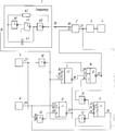
Схема электронного временного устройства взрывателей и ПИМов приведена на чертеже. В его состав входят последовательно соединенные генератор 1, делитель частоты 2, счетчик импульсов 3, исполнительное устройство 4, формирователь сигнала сброса 5, источник пускового сигнала 6, D-триггер 7, RS-триггер 8, НЕ RS-триггер 9, инверторы 10, 11, 12, логический элемент 2 ИЛИ НЕ 13 и логический элемент 2 ИЛИ И НЕ 14.A diagram of an electronic temporary device for fuses and PIMs is shown in the drawing. It consists of a series-connected
D-триггер 7 имеет информационный D-вход 15, С-вход синхронизации 16, S-вход установки 17, инверсный выход 18.D-
RS-триггер 8 имеет 2 R входа сброса 19, 20, S-вход установки 21 и инверсный выход 22. НЕ RS-триггер 9 имеет R-вход сброса 23, 2 S-входа установки 24, 25 и выход 26.The RS-flip-
Выход 27 формирователя сигнала сброса соединен с первым R-входом сброса 19 RS-триггера 8, а через инвертор 10 с входом 28 логического элемента 2 ИЛИ И НЕ 14. Выход 29 источника пускового сигнала 6 соединен с S-входом установки 21 RS-триггера 8 и первым входом 30 логического элемента 2 ИЛИ НЕ 13. Инверсный выход 18 D-триггера 7 соединен с первым входом ИЛИ 31 логического элемента 2 ИЛИ И НЕ 14.The
Выход 32 логического элемента 2 ИЛИ И НЕ 14 соединен с входом сброса 33 делителя частоты 2 и через инвертор 11 с R-входом сброса 23 НЕ RS-триггера 9.The
Инверсный выход 22 RS-триггера 8 соединен со вторым входом ИЛИ 34 логического элемента 2 ИЛИ И НЕ 14 и S-входом установки 24 НЕ RS-триггера 9. Кроме того инверсный выход 22' RS-триггера 8 соединен с объединенными D-входом информации 15 и S-входом установки 17 D-триггера 7, а также с входом запрета 35 генератора 1. С-вход синхронизации 16 D-триггера 7 соединен с выходом 36 генератора 1, одновременно соединенным со счетным входом 30 делителя частоты 2.The
Выход 37 делителя частоты через инвертор 12 соединен с S-входом установки 25 НЕ RS-триггера 9. Выход 26 НЕ RS-триггера 9 соединен с входом 38 логического элемента 2 ИЛИ НЕ 13. Выход этого логического элемента подсоединен к R-входу сброса 20 RS-триггера 8.The
Устройство работает следующим образом. Перед началом отсчета времени на выходе 27 формирователя сигнала сброса 5 формируется импульс логической "1", поступающий на R-вход сброса 19 RS-триггера 8, устанавливая его в исходное состояние, соответствующее сигналу логической "1" на выходе 22. Через инвертор 10 импульс логической "1" с выхода 27 формирователя сигнала сброса 5 поступает в виде импульса логического "0" на вход И 28 логического элемента 2 ИЛИ И НЕ 14, на выходе 32 которого появляется импульс логической "1". Этот импульс поступает на вход сброса 33 делителя частоты 2, устанавливая его в исходное состояние.The device operates as follows. Before starting the countdown, the output of the shaper of the
Одновременно указанный импульс с выхода 32 логического элемента 2 ИЛИ И НЕ 14 через инвертор 11, поступая на R-вход сброса 23 НЕ RS-триггера 9, устанавливает его в исходное состояние, соответствующее сигналу логического "0" на его выходе 26. До пуска боеприпаса на выходе 29 источника пускового сигнала 6 уровень логического "0", поступающий на вход 30 логического элемента 2 ИЛИ НЕ 13 и далее на R-вход сброса 20 RS-триггера 8. Этим сигналом подтверждается исходное состояние указанного триггера, соответствующее уровню логической "1" на выходе 22.Simultaneously, the specified pulse from the
Таким образом, после сброса триггеры 7, 8, 9 находятся в исходном состоянии, генератор 1 не работает из-за запрета по его входу 35.Thus, after the reset, the
При приходе пускового сигнала на выходе 29 источника пускового сигнала 6 появляется импульс логической "1". Это импульс поступает на вход 30 логического элемента 2 ИЛИ НЕ 13. На выходе этого логического элемента логический "0", поступающий на R-вход сброса 20 RS-триггера 8, снимая сигнал сброса с RS-триггера 8. Одновременно импульс логической "1" поступает на S-вход установки 21 RS-триггера 8, переключая его в состояние, соответствующее логическому "0" на его выходе 22, сигналом с которого по входу 35 снимается запрет на работу генератора 1. На выходе 36 генератора начинают формироваться импульсы. Одновременно с этим на входе 34 логического элемента 2 ИЛИ И НЕ 14 логический "0". До появления импульса на выходе 36 генератора 1, связанном с С-входом 16 D-триггера 7, на выходе 18 указанного триггера логический "0", поступающий на вход 31 логического элемента 2 ИЛИ И НЕ 14.When the trigger signal arrives at the
Это приводит к появлению логической "1" на выходе 32 логического элемента 2 ИЛИ И НЕ 14. Эта логическая "1", поступая на вход сброса 33 делителя частоты 2, сбрасывает его в исходное состояние, а, поступая через инвертор 11 на R-вход сброса 23 НЕ RS-триггера 9, подтверждает его исходное состояние.This leads to the appearance of a logical "1" at the
Логический "0" с выхода 22 RS-триггера 8 поступает на объединенный информационный D-вход 15 и S-вход установки 17 RS-триггера 7. Однако состояние триггера 7 до прихода импульса от генератора 1 на его С-вход синхронизации 16 не изменяется. После начала работы генератора 1 импульс с его выхода 36 поступает на С-вход синхронизации 16 D-триггера 7, переключая его в состояние, соответствующее логической "1" на его выходе 18 и связанным с ним входом 31 логического элемента 2 ИЛИ И НЕ 14. В результате этого на выходе 32 логического элемента 2 ИЛИ И НЕ 14 логический "0". Сброс по входу 33 делителя частоты 2 снят. Также снят сброс по R-входу сброса 23 триггера 9.Logical "0" from the
Если до прихода импульса с выхода 37 делителя частоты 2 пусковой сигнал закончится, он трактуется как помеха. При этом на выходе 29 появляется сигнал логического "0", поступающий на вход 30 логического элемента 2 ИЛИ НЕ 13. На втором входе 38 этого элемента также логический "0", поступающий с выхода 26 НЕ RS-триггера 9. На выходе логического элемента 13 логическая "1", поступающая на вход R-сброса 20 RS-триггера 8. Этот RS-триггер устанавливается в исходное состояние, соответствующее сигналу логической "1" на его выходе 22. Работа генератора 1 по входу 35 останавливается. Схема возвращается в исходное состояние.If, before the pulse arrives from the
При повторном появлении пускового сигнала процессы повторяются.When the trigger signal reappears, the processes repeat.
Формируется импульс сброса на входе 33 делителя частоты 2, сигнал запрета с входа 35 генератора 1 снимается.A reset pulse is generated at the
Если до окончания пускового сигнала на выходе делителя частоты 37 появляется импульс логической "1", то, поступая через инвертор 12 в виде логического "0" на S-вход установки 25 НЕ RS-триггера 9, он устанавливает его в состояние, соответствующее логической "1" на выходе 26. На входе 38 логического элемента 2 ИЛИ НЕ 13 появляется логическая "1". Эта логическая "1" блокирует влияние сигнала на выводе 29 источника пускового сигнала 6 на сигнал на R-входе сброса 20 RS-триггера 8. На указанном входе сигнал логического "0". Теперь, независимо от пускового сигнала, в исходное состояние RS-триггер 8 вернуться не может. Сигнал запрета на входе 35 генератора 1 не появляется. Импульсы с выхода 36 генератора 1 поступают на вход 30 делителя частоты 2 и далее с его выхода 37 на счетчик импульсов 3. При заполнении счетчика 3 на его выходе появляется сигнал, поступающий на исполнительное устройство 4, по команде которого осуществляется необходимое действие (дальнее взведение, дистанционное действие взрывателя и др.).If, before the end of the start signal, a logical "1" pulse appears at the output of the
Таким образом, при длительности пускового сигнала менее времени появления первого импульса на выходе 37 делителя частоты 2, время действия временным устройством не отсчитывается.Thus, when the duration of the start signal is less than the time of the appearance of the first pulse at the
Источник пускового сигнала 6 может быть построен с использованием инерционного замыкателя или пьезодатчика инерционных нагрузок, выдающих сигнал при пуске боеприпаса (снаряда, ракеты).The
Появление помехи по цепи 29 пускового сигнала несанкционированное формирование пускового сигнала (при случайном падении боеприпаса, вибрациях, ударных нагрузках до пуска боеприпаса) не приводят к отсчету времени. Отсчет времени и формирование выходной команды исполнительным устройством 4 будут осуществлены только при длительности tp пускового сигнала, равной или превышающей время tдел появления первого выходного импульса делителя частоты 2, т.е. приThe appearance of interference on the
tp≥tдел.t p ≥t Affairs.
Не произойдет отсчета времени и при появлении многократных импульсов на выходе источника пускового сигнала 6 при длительности каждого из них менее tдел, так как при появлении на выходе 29 каждого импульса осуществляется обнуление делителя частоты 2.There will also be no countdown when multiple pulses appear at the output of the
Предложенное техническое решение позволяет начать отсчет времени сразу же после появления пускового сигнала, вернуться в исходное состояние при малой длительности пускового сигнала и продолжить и завершить отсчет времени при длительности пускового сигнала, превышающей tдел.The proposed technical solution allows you to start the countdown immediately after the appearance of the start signal, return to its original state with a short duration of the start signal and continue and complete the countdown when the duration of the start signal exceeds t div .
Генератор 1 может быть выполнен, как это показано на чертеже, на инверторах 39, 40, логическом элементе 2 ИЛИ НЕ 41, резисторе 42 и конденсаторе 43.
В этом случае длительность импульса сброса tсбр, поступающего на вход 33 делителя частоты 2 при появлении пускового сигнала на выводе 29, определяется выражением:In this case, the pulse duration t RRF reset input to the
tcбp=RCln2≈0,7RC,t cbp = RCln2≈0.7RC,
где R, С - соответственно сопротивление и емкость резистора 42 и конденсатора 43.where R, C - respectively, the resistance and capacitance of the
Период Tг генератора в этой схеме определяется выражениемThe period T g of the generator in this scheme is determined by the expression
Тг=2RCln3≈2,2RC.T g = 2RCln3≈2.2RC.
Длительность импульса сброса tсбр составляетThe pulse duration t RRF is reset
![]()
![]()
Приведем пример реализации для случая использования временного устройства во взрывателе реактивного снаряда.Here is an example implementation for the case of using a temporary device in a fuse for a rocket projectile.
Период генератора Тг=95,4 мкс. Делитель частоты 2 построен на 9-ти последовательно соединенных счетных триггерах. Его коэффициент деления Кd=29=512.Generator period T g = 95.4 μs.
Первый импульс с выхода 37 делителя частоты 2 формируется при поступлении на него N1дел, импульсов.The first pulse from the
N1дел=28=256.N 1del = 2 8 = 256.
Счетчик импульсов 3 формирует выходной сигнал на исполнительное устройство 4 при поступлении на него Nсч=1024 импульсов.The
В этом случае время Тd, формируемое временным устройством, равноIn this case, the time T d generated by the temporary device is
Td=KdNсчTг=512·1024·95,4·10-6=50 с.T d = K d N sc T g = 512 · 1024 · 95.4 · 10 -6 = 50 s.
Длительность импульса сброса tсбр, формируемого на входе 33 делителя частоты 2 при поступлении по выводу 29 пусковой команды, равнаDischarge
tсбр=0,32·Тг=0,32·95,4·10-6=30,5·10-6 с.t SBR = 0.32 · T g = 0.32 · 95.4 · 10 -6 = 30.5 · 10 -6 s.
Длительность tp пускового сигнала, необходимая для отсчета времени и формирования временным устройством выходной команды, составляетThe duration t p of the start signal, necessary for counting the time and the formation of the output device by the temporary device, is
tp≥tдел=N1делТг=256·95,4·10-6=24,4·10-3c.t p ≥t cases 1del = N T d = 256 · 95.4 · 10 -6 = 24.4 · 10 -3 c.
Такая длительность пускового сигнала возможна только при нормальном движении реактивного снаряда на начальном участке траектории полета.Such a duration of the launch signal is possible only with normal movement of the rocket in the initial section of the flight path.
Проведенные лабораторно-стендовые испытания подтвердили достижение технического результата заявляемого способа - высокую помехозащищенность электронного временного устройства взрывателя, исключение возможности несанкционированного запуска временного устройства, отсчета им времени и формирования команды на исполнительное устройство в моменты, не связанные с началом движения боеприпаса.The laboratory bench tests have confirmed the achievement of the technical result of the proposed method - high noise immunity of the electronic temporary fuse device, eliminating the possibility of unauthorized starting of the temporary device, counting the time and forming a command for the executive device at moments not related to the beginning of the movement of ammunition.
Claims (1)
Priority Applications (1)
| Application Number | Priority Date | Filing Date | Title |
|---|---|---|---|
| RU2011143892/03A RU2492418C2 (en) | 2011-10-28 | 2011-10-28 | Electronic temporary device of detonators and safety and arming mechanisms |
Applications Claiming Priority (1)
| Application Number | Priority Date | Filing Date | Title |
|---|---|---|---|
| RU2011143892/03A RU2492418C2 (en) | 2011-10-28 | 2011-10-28 | Electronic temporary device of detonators and safety and arming mechanisms |
Publications (2)
| Publication Number | Publication Date |
|---|---|
| RU2011143892A RU2011143892A (en) | 2013-05-10 |
| RU2492418C2 true RU2492418C2 (en) | 2013-09-10 |
Family
ID=48788528
Family Applications (1)
| Application Number | Title | Priority Date | Filing Date |
|---|---|---|---|
| RU2011143892/03A RU2492418C2 (en) | 2011-10-28 | 2011-10-28 | Electronic temporary device of detonators and safety and arming mechanisms |
Country Status (1)
| Country | Link |
|---|---|
| RU (1) | RU2492418C2 (en) |
Cited By (1)
| Publication number | Priority date | Publication date | Assignee | Title |
|---|---|---|---|---|
| CN106788400A (en) * | 2016-12-05 | 2017-05-31 | 中国科学技术大学 | The dutycycle quadrature divider of broadband programmable 50% of high-speed low-power-consumption |
Citations (6)
| Publication number | Priority date | Publication date | Assignee | Title |
|---|---|---|---|---|
| US4240350A (en) * | 1977-09-16 | 1980-12-23 | Werkzeugmaschinenfabrik Oerlikon-Buhrle | Electronic fuze |
| US4389937A (en) * | 1980-01-29 | 1983-06-28 | Mefina S.A. | Fuze for non-spinning projectiles |
| US4750424A (en) * | 1986-03-06 | 1988-06-14 | Honeywell Regelsysteme Gmbh | Running time display for a projectile time fuze |
| RU2076303C1 (en) * | 1993-03-02 | 1997-03-27 | Специальное конструкторское бюро "Ротор" | Signal generator for setting of electronic time fuze with inductive control circuit |
| RU2169344C1 (en) * | 2000-06-06 | 2001-06-20 | Государственное унитарное предприятие "Научно-исследовательский институт "Поиск" | Remote-control blasting devices for jet projectiles of salvo-fire systems |
| RU2240493C1 (en) * | 2003-08-04 | 2004-11-20 | Федеральное государственное унитарное предприятие "Научно-исследовательский институт "Поиск" | Time fuze of shells of salvo-fire jet-propelled systems (sfjps) |
-
2011
- 2011-10-28 RU RU2011143892/03A patent/RU2492418C2/en not_active IP Right Cessation
Patent Citations (6)
| Publication number | Priority date | Publication date | Assignee | Title |
|---|---|---|---|---|
| US4240350A (en) * | 1977-09-16 | 1980-12-23 | Werkzeugmaschinenfabrik Oerlikon-Buhrle | Electronic fuze |
| US4389937A (en) * | 1980-01-29 | 1983-06-28 | Mefina S.A. | Fuze for non-spinning projectiles |
| US4750424A (en) * | 1986-03-06 | 1988-06-14 | Honeywell Regelsysteme Gmbh | Running time display for a projectile time fuze |
| RU2076303C1 (en) * | 1993-03-02 | 1997-03-27 | Специальное конструкторское бюро "Ротор" | Signal generator for setting of electronic time fuze with inductive control circuit |
| RU2169344C1 (en) * | 2000-06-06 | 2001-06-20 | Государственное унитарное предприятие "Научно-исследовательский институт "Поиск" | Remote-control blasting devices for jet projectiles of salvo-fire systems |
| RU2240493C1 (en) * | 2003-08-04 | 2004-11-20 | Федеральное государственное унитарное предприятие "Научно-исследовательский институт "Поиск" | Time fuze of shells of salvo-fire jet-propelled systems (sfjps) |
Cited By (2)
| Publication number | Priority date | Publication date | Assignee | Title |
|---|---|---|---|---|
| CN106788400A (en) * | 2016-12-05 | 2017-05-31 | 中国科学技术大学 | The dutycycle quadrature divider of broadband programmable 50% of high-speed low-power-consumption |
| CN106788400B (en) * | 2016-12-05 | 2019-11-22 | 中国科学技术大学 | The 50% duty ratio quadrature divider of broadband programmable of high-speed low-power-consumption |
Also Published As
| Publication number | Publication date |
|---|---|
| RU2011143892A (en) | 2013-05-10 |
Similar Documents
| Publication | Publication Date | Title |
|---|---|---|
| US8887640B1 (en) | Electro-mechanical fuze for hand grenades | |
| US8661982B2 (en) | Adaptable smart warhead and method for use | |
| US4829899A (en) | Timing control system | |
| EP0100130A2 (en) | Fuze actuating system having a variable impact delay | |
| EP2867609B1 (en) | Intermediate voltage arming | |
| US6295932B1 (en) | Electronic safe arm and fire device | |
| US4541341A (en) | Self-checking arming and firing controller | |
| RU2451896C1 (en) | Detonating cap | |
| JPH09159400A (en) | Programming method of time fuse for missile | |
| RU2492418C2 (en) | Electronic temporary device of detonators and safety and arming mechanisms | |
| US6401621B1 (en) | Electronic safe and arm apparatus for initiating a pyrotechnic | |
| EP3341675B1 (en) | Firing arrangement | |
| EP1840497A1 (en) | Weapon arming system and method | |
| RU2579321C1 (en) | Detonation commands retarder of ballistic type | |
| RU2603654C1 (en) | Method for controlling pyro device blasting | |
| JPH0215799B2 (en) | ||
| RU2296943C1 (en) | Method for initiation and formation of blast wave in main explosive charge | |
| RU2532509C1 (en) | Fuse device for torpedoes | |
| RU2489678C2 (en) | Electronic remote detonating fuse of missile projectile | |
| Babu et al. | Programmable electronic delay device for detonator | |
| RU2550705C1 (en) | Deceleration of knocking commands in onboard acs | |
| EP0275445B1 (en) | Random time fuse for submunition exploding unpredictably | |
| RU2787169C1 (en) | Method for multiple contactless installation and counting of time of action of remote fuse | |
| US9625243B1 (en) | Electronic setback validation for fuzes | |
| RU2764513C1 (en) | Apparatus for blasting penetrating-type warheads in critical conditions of hull deformation |
Legal Events
| Date | Code | Title | Description |
|---|---|---|---|
| MM4A | The patent is invalid due to non-payment of fees |
Effective date: 20141029 |