RU2485382C2 - Valve block with double-control mechanism - Google Patents
Valve block with double-control mechanism Download PDFInfo
- Publication number
- RU2485382C2 RU2485382C2 RU2010146799/06A RU2010146799A RU2485382C2 RU 2485382 C2 RU2485382 C2 RU 2485382C2 RU 2010146799/06 A RU2010146799/06 A RU 2010146799/06A RU 2010146799 A RU2010146799 A RU 2010146799A RU 2485382 C2 RU2485382 C2 RU 2485382C2
- Authority
- RU
- Russia
- Prior art keywords
- valve
- pressure
- control
- actuator
- inlet
- Prior art date
Links
Images


Classifications
-
- G—PHYSICS
- G05—CONTROLLING; REGULATING
- G05D—SYSTEMS FOR CONTROLLING OR REGULATING NON-ELECTRIC VARIABLES
- G05D16/00—Control of fluid pressure
- G05D16/04—Control of fluid pressure without auxiliary power
- G05D16/06—Control of fluid pressure without auxiliary power the sensing element being a flexible membrane, yielding to pressure, e.g. diaphragm, bellows, capsule
- G05D16/063—Control of fluid pressure without auxiliary power the sensing element being a flexible membrane, yielding to pressure, e.g. diaphragm, bellows, capsule the sensing element being a membrane
- G05D16/0675—Control of fluid pressure without auxiliary power the sensing element being a flexible membrane, yielding to pressure, e.g. diaphragm, bellows, capsule the sensing element being a membrane the membrane acting on the obturator through a lever
- G05D16/0694—Control of fluid pressure without auxiliary power the sensing element being a flexible membrane, yielding to pressure, e.g. diaphragm, bellows, capsule the sensing element being a membrane the membrane acting on the obturator through a lever using a spring-loaded membrane with a spring-loaded slideable obturator
-
- G—PHYSICS
- G05—CONTROLLING; REGULATING
- G05D—SYSTEMS FOR CONTROLLING OR REGULATING NON-ELECTRIC VARIABLES
- G05D16/00—Control of fluid pressure
- G05D16/02—Modifications to reduce the effects of instability, e.g. due to vibrations, friction, abnormal temperature, overloading or unbalance
-
- G—PHYSICS
- G05—CONTROLLING; REGULATING
- G05D—SYSTEMS FOR CONTROLLING OR REGULATING NON-ELECTRIC VARIABLES
- G05D16/00—Control of fluid pressure
- G05D16/04—Control of fluid pressure without auxiliary power
- G05D16/0404—Control of fluid pressure without auxiliary power with two or more controllers mounted in parallel
-
- Y—GENERAL TAGGING OF NEW TECHNOLOGICAL DEVELOPMENTS; GENERAL TAGGING OF CROSS-SECTIONAL TECHNOLOGIES SPANNING OVER SEVERAL SECTIONS OF THE IPC; TECHNICAL SUBJECTS COVERED BY FORMER USPC CROSS-REFERENCE ART COLLECTIONS [XRACs] AND DIGESTS
- Y10—TECHNICAL SUBJECTS COVERED BY FORMER USPC
- Y10T—TECHNICAL SUBJECTS COVERED BY FORMER US CLASSIFICATION
- Y10T137/00—Fluid handling
- Y10T137/7722—Line condition change responsive valves
- Y10T137/7754—Line flow effect assisted
- Y10T137/7756—Reactor surface separated from flow by apertured partition
- Y10T137/7757—Through separate aperture
-
- Y—GENERAL TAGGING OF NEW TECHNOLOGICAL DEVELOPMENTS; GENERAL TAGGING OF CROSS-SECTIONAL TECHNOLOGIES SPANNING OVER SEVERAL SECTIONS OF THE IPC; TECHNICAL SUBJECTS COVERED BY FORMER USPC CROSS-REFERENCE ART COLLECTIONS [XRACs] AND DIGESTS
- Y10—TECHNICAL SUBJECTS COVERED BY FORMER USPC
- Y10T—TECHNICAL SUBJECTS COVERED BY FORMER US CLASSIFICATION
- Y10T137/00—Fluid handling
- Y10T137/7722—Line condition change responsive valves
- Y10T137/7781—With separate connected fluid reactor surface
- Y10T137/7793—With opening bias [e.g., pressure regulator]
- Y10T137/7794—With relief valve
-
- Y—GENERAL TAGGING OF NEW TECHNOLOGICAL DEVELOPMENTS; GENERAL TAGGING OF CROSS-SECTIONAL TECHNOLOGIES SPANNING OVER SEVERAL SECTIONS OF THE IPC; TECHNICAL SUBJECTS COVERED BY FORMER USPC CROSS-REFERENCE ART COLLECTIONS [XRACs] AND DIGESTS
- Y10—TECHNICAL SUBJECTS COVERED BY FORMER USPC
- Y10T—TECHNICAL SUBJECTS COVERED BY FORMER US CLASSIFICATION
- Y10T137/00—Fluid handling
- Y10T137/7722—Line condition change responsive valves
- Y10T137/7781—With separate connected fluid reactor surface
- Y10T137/7793—With opening bias [e.g., pressure regulator]
- Y10T137/7795—Multi-stage
-
- Y—GENERAL TAGGING OF NEW TECHNOLOGICAL DEVELOPMENTS; GENERAL TAGGING OF CROSS-SECTIONAL TECHNOLOGIES SPANNING OVER SEVERAL SECTIONS OF THE IPC; TECHNICAL SUBJECTS COVERED BY FORMER USPC CROSS-REFERENCE ART COLLECTIONS [XRACs] AND DIGESTS
- Y10—TECHNICAL SUBJECTS COVERED BY FORMER USPC
- Y10T—TECHNICAL SUBJECTS COVERED BY FORMER US CLASSIFICATION
- Y10T137/00—Fluid handling
- Y10T137/7722—Line condition change responsive valves
- Y10T137/7781—With separate connected fluid reactor surface
- Y10T137/7793—With opening bias [e.g., pressure regulator]
- Y10T137/7831—With mechanical movement between actuator and valve
Abstract
Description
Настоящая заявка претендует на приоритет по предварительной заявке на патент США №61/046788, поданной 21 апреля 2008 года, под названием "Блок клапанов с механизмом двойного контроля", включенной в данный документ путем ссылки.This application claims priority to provisional application for US patent No. 61/046788, filed April 21, 2008, under the name "Valve block with a double control mechanism", incorporated herein by reference.
Область техники, к которой относится изобретениеFIELD OF THE INVENTION
Данное изобретение относится к устройствам, регулирующим поток жидкости, таким как регуляторы давления газа, и, в частности, к регуляторам со вспомогательными устройствами, измеряющими давление в заданных точках устройства, таких как устройство контроля избыточного давления, активатор закрытия задвижки, маркерное сигнальное устройство и тому подобных.This invention relates to devices that control the flow of liquid, such as gas pressure regulators, and, in particular, to regulators with auxiliary devices that measure pressure at predetermined points of the device, such as an overpressure control device, gate closure activator, marker signal device, and the like like that.
Уровень техникиState of the art
Стандартные газораспределительные системы подачи газа могут различаться по требованиям к давлению в зависимости от нагрузки системы, климатических условий, источника снабжения и/или других факторов. При этом, большинство объектов конечного потребителя оборудовано газовыми приборами, такими как нагреватели, печи и т.д., требующими доставку газа в соответствии с установленным давлением и без превышения максимальной емкости регулятора давления газа. Таким образом, системы распределения оснащены регуляторами давления газа для обеспечения качества газа согласно требованиям устройств конечного потребления. Традиционные регуляторы давления газа, как правило, оснащены механизмом замкнутой системы управления клапанами для измерения и контроля давления поставляемого газа.Standard gas distribution systems for gas supply may vary in pressure requirements depending on the system load, climatic conditions, supply source and / or other factors. Moreover, most of the end-user facilities are equipped with gas appliances, such as heaters, furnaces, etc., requiring gas delivery in accordance with the set pressure and without exceeding the maximum capacity of the gas pressure regulator. Thus, the distribution systems are equipped with gas pressure regulators to ensure gas quality according to the requirements of end-use devices. Traditional gas pressure regulators are typically equipped with a closed valve control mechanism to measure and control the pressure of the gas supplied.
Помимо замкнутой системы управления, некоторые традиционные регуляторы газа оснащены регулирующим запорным механизмом для улучшения реакции регулятора давления газа на изменения выходного давления. Регулирующий запорный механизм применяется для уменьшения влияния входного давления на функционирование регулятора давления газа. Входное давление находится в жидкостной связи с регулирующей мембраной, которая давит с той же силой, что и выходное давление, на управляющий элемент регулятора давления газа, но в противоположном направлении. Таким образом, как только входное давление меняется, применяется соответствующее воздействие для балансировки воздействия, созданного входным давлением, так, как это описано далее, таким образом, регулятор давления газа приводится в действие только выходным давлением газа.In addition to a closed-loop control system, some traditional gas regulators are equipped with a regulating shut-off mechanism to improve the response of the gas pressure regulator to changes in output pressure. The regulating locking mechanism is used to reduce the influence of the inlet pressure on the functioning of the gas pressure regulator. The inlet pressure is in fluid communication with the control membrane, which presses with the same force as the outlet pressure on the control element of the gas pressure regulator, but in the opposite direction. Thus, as soon as the inlet pressure changes, the corresponding action is applied to balance the effect created by the inlet pressure, as described below, thus, the gas pressure regulator is actuated only by the gas outlet pressure.
Некоторые традиционные регуляторы давления газа также оснащены вспомогательными устройствами, такими как устройство контроля избыточного давления, запорные механизмы, маркерное сигнальное устройство и тому подобными, которые приводятся в действие, если измеряемое входное давление, например давление потока после регулятора, отличается от заранее определенного стандартного диапазона давлений. Устройство контроля избыточного давления контролирует давление на выходе из регулятора в случае, если регулятор неисправен и выходное давление увеличивается до нежелательного уровня. В случае неисправности регулятора и роста выходного давления выше заранее заданного значения, устройство контроля избыточного давления закрывает отверстие в регулирующем клапане и перекрывает поток газа, поступающий в нижеследующие узлы газораспределительной системы. Как только потребление увеличивается и/или проблема с регулятором устраняется, т.е. выходное давление падает, устройство контроля открывает отверстие клапана и, соответственно, обеспечивает дальнейшее движение газа в системе.Some traditional gas pressure regulators are also equipped with auxiliary devices, such as an overpressure control device, shut-off mechanisms, a marker signal device and the like, which are activated if the measured inlet pressure, for example, the flow pressure after the regulator, differs from the predetermined standard pressure range . The overpressure control device controls the pressure at the outlet of the regulator in case the regulator is faulty and the outlet pressure increases to an undesirable level. In the event of a controller malfunction and an increase in the outlet pressure above a predetermined value, the overpressure control device closes the hole in the control valve and shuts off the gas flow entering the following gas distribution system nodes. As soon as consumption increases and / or the problem with the regulator is eliminated, i.e. the outlet pressure drops, the control device opens the valve opening and, accordingly, provides further gas movement in the system.
В других моделях, регуляторы давления газа нуждаются в дополнительных предохранительных устройствах, перекрывающих газовый поток в случае неисправности регулятора, или в других условиях, провоцирующих рост или падение давления на выходе регулятора давления газа. Обычно быстродействующие предохранительные запорные клапаны используются для того, чтобы перекрыть газовый поток в случае возникновения одной (или более) из таких ситуаций. Предохранительный запорный клапан обычно располагается на входе в регулятор давления таким образом, чтобы не допустить попадания газа в редуктор давления газа в случае повышенного или пониженного давления. Предохранительный запорный клапан контролирует давление на выходе регулятора, чтобы оно оставалось в пределах между максимальным и минимальным допустимыми значениями. Если выходное давление превышает максимально допустимое или падает ниже минимального заданного значения, предохранительный запорный клапан закрывается, перекрывая газовый поток в регулятор давления газа и предотвращая нежелательную утечку газа. Закрывшись, быстродействующий запорный клапан обычно остается в закрытом состоянии до того момента, пока не будет произведен ремонт и клапан не будет открыт вручную. В других моделях может использоваться другое вспомогательное устройство - маркерное сигнальное устройство, которое не сбрасывает давление в случае его превышения, а вместо этого сбрасывает некоторое количество газа до появления запаха, предупреждающего конечного пользователя о необходимости связаться с поставщиком газа для ремонта и обслуживания регулятора давления газа.In other models, gas pressure regulators need additional safety devices that block the gas flow in case of a regulator malfunction, or in other conditions that provoke an increase or decrease in pressure at the outlet of the gas pressure regulator. Typically, high-speed safety shut-off valves are used to shut off gas flow in the event of one (or more) of these situations. The safety shut-off valve is usually located at the inlet to the pressure regulator in such a way as to prevent gas from entering the gas pressure reducer in case of high or low pressure. A safety shut-off valve controls the pressure at the outlet of the regulator so that it remains between the maximum and minimum permissible values. If the outlet pressure exceeds the maximum permissible or falls below the minimum set value, the safety shut-off valve closes, blocking the gas flow into the gas pressure regulator and preventing undesired gas leakage. When closed, the high-speed shut-off valve usually remains closed until it is repaired and the valve is manually opened. Other models may use another auxiliary device, a marker signal device, which does not release pressure if it is exceeded, but instead releases a certain amount of gas until an odor appears, warning the end user to contact the gas supplier for repair and maintenance of the gas pressure regulator.
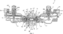
На фиг.1 (закрытое положение) и 2 (полностью открытое положение) показан традиционный регулятор давления газа 10. Регулятор 10 в общих чертах состоит из привода 12 и регулирующего клапана 14. Регулирующий клапан 14 контролирует поступление газа на входе 16 из, например, газораспределительной системы, и поступление газа на выходе 18, к объектам конечного потребителя, таким как фабрики, рестораны, жилые здания и т.д., имеющим один или более газовый прибор. Кроме того, регулирующий клапан 14 включает в себя клапанное окно 20, расположенное между входом 16 и выходом 18. Газ перемещается от входа 16 до выхода 18 только через клапанное окно 20 регулирующего клапана 14.1 (closed position) and 2 (fully open position) shows a traditional
Привод 12 связан с регулирующим клапаном 14 для обеспечения давления на выходе 18 регулирующего клапана 14, т.е. выходного давления в соответствии с требуемым выходным или контрольным давлением, т.е. так называемым заданным давлением. Следовательно, привод 12 находится в жидкостной связи с регулирующим клапаном 14 через отверстие клапана 22 и отверстие привода 24. В приводе 12 находится узел управления 26 для измерения и регулировки выходного давления из регулирующего клапана 14. В частности, узел управления 26 содержит мембрану 28, поршень 30 и рукоятку управления 32, с функционально связанной клапанной тарелкой 34. Традиционная конструкция клапанной тарелки 34 регулирующего запорного механизма включает в себя, как правило, цилиндрический корпус 36 и герметизирующую вставку 38, прикрепленную к корпусу 36. Узел управления 26 также может быть оснащен регулирующим запорным механизмом 40 с регулирующей мембраной 42 для выравнивания силы, оказываемой давлением на входе на клапанную тарелку 34. Мембранный механизм 28 измеряет давление на выходе регулирующего клапана 14 с помощью трубки Пито 44, при этом выход 18 находится в жидкостной связи с полостью привода 12 и нижней частью мембраны 28. Далее в узле управления 26 находится регулирующая пружина 46, сцепленная с верхней частью мембраны 28 и предназначенная для компенсации измеряемого выходного давления. Таким образом, требуемое выпускное давление, которое также называется контрольным давлением, или заданным давлением привода, устанавливается при помощи соответствующей регулирующей пружины 46.The
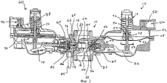
Мембрана 28 функционально соединена с рукояткой управления 32, и, таким образом, клапанная тарелка 34 посредством поршня 30 контролирует открытие регулирующего клапана 14, основываясь на измеренном выпускном давлении. Например, в случае, если конечный пользователь использует такой прибор, как, например, обогреватель, увеличивая, таким образом, потребность в газе в распределительной системе на выходе регулятора 10, выходной поток увеличивается, уменьшая тем самым выпускное давление. Соответственно, мембрана 28 фиксирует это уменьшение выпускного давления. Это позволяет регулирующей пружине 46 расшириться и передвинуть поршень 30 и правую часть рукоятки управления 32 в нижнее положение, относительно расположения на фиг.1. Это перемещение рукоятки управления 32 отодвигает клапанную тарелку 34 от отверстия клапана 20, что открывает регулирующий клапан 14. На фиг.2 показана клапанная тарелка 34 в нормальном, открытом рабочем положении. Прибор, настроенный таким образом, может проводить газ через клапанное окно 20 на выход 18 регулирующего клапана 14.The
В стандартном регуляторе давления газа 10, показанном на фиг.1 и 2, узел управления 26 функционирует в дальнейшем как перепускной клапан, как показано выше. В частности, узел управления 26 оснащен уравновешивающей пружиной 48 и выпускным клапаном 50. Мембрана 28 содержит отверстие 52, в середине которого, а также через поршень 30 проходит уплотняющая манжета 54. Уравновешивающая пружина 48 находится между поршнем 30 и мембраной 28 для того, чтобы в нормальном режиме эксплуатации смещать мембрану 28 относительно уплотняющей манжеты 54 для перекрытия отверстия 52. В случае возникновения неполадок, таких как поломка рукоятки управления 32, клапанная тарелка 34 более не может напрямую контролировать узел управления 26, следовательно, входной поток передвигает клапанную тарелку 34 до предельно открытого положения. Это позволяет максимальному количеству газа попадать в привод 12. Таким образом, как только газ заполняет привод 12, давление на мембрану 28 возрастает, выдавливая мембрану 28 из уплотняющей манжеты 54, тем самым воздействуя на отверстие 52. Вследствие этого газ проходит через отверстие 52 в мембрану 28 и по направлению к выпускному клапану 50. Выпускной клапан 50 состоит из стержня клапана 56 и оттяжной пружины 58, давящей в закрытом положении на стержень клапана 56. В случае если давление внутри привода 12 и близлежащего выпускного клапана 50 достигает заданного предела, стержень клапана 56 смещается вверх относительно положения оттяжной пружины 58 и открывается, тем самым выпуская газ в атмосферу и уменьшая давление в регуляторе 10.In the standard
Несмотря на то что выпускной клапан 50 выпускает газ из привода 12, он обычно не сбрасывает давление в достаточной степени, и выходное давление не падает ниже верхнего предела значений, для контроля которых разработан регулятор давления газа 10. Для такой ситуации существуют вспомогательные устройства, рассмотренные выше, которые могут обеспечить контроль и перекрыть поток газа или, как минимум, предупредить пользователя о превышении допустимого давления. В конструкции, показанной на фиг.1 и 2, контроллер избыточного давления 60 срабатывает после поломки регулятора давления газа 10 и перекрывает поток газа через регулирующий клапан 14 до тех пор, пока выходное давление не упадет. В проиллюстрированном примере контроллер 60 имеет такую же конфигурацию, как и привод 12. Контроллер 60 связан с регулирующим клапаном 14 напротив привода 12 и на входе в отверстие клапана 20. Вследствие этого, контроллер 60 находится в жидкостной связи с регулирующим клапаном 14 через впускное отверстие клапана 62 и отверстие устройства контроля 64, связанных с корпусом контроллера 66. Контроллер 60 имеет узел управления 68 для измерения давления после регулирующего клапана 14 и закрытия клапана 14, если выходное давление достигает контрольного заданного значения или давления отсечки. Узел управления 68 состоит из мембраны 70, поршня 72 и рукоятки управления 74 с функционально связанной с ней клапанной тарелкой 76. Контроллер 60 имеет регулирующий запорный механизм, а клапанная тарелка 76 состоит из основного цилиндрического корпуса 78 и герметизирующей вставки 80, прикрепленной к корпусу 78. Регулирующий запорный механизм включает в себя регулирующую мембрану 82 для уравновешивания силы, прикладываемой входным давлением к клапанной тарелке 76.Despite the fact that the exhaust valve 50 releases gas from the
Мембрана контроллера 70 измеряет давление на выходе из регулирующего клапана 14 посредством внешнего трубопровода обратной связи по давлению на выходе 84, соединенному с отверстием 86 корпуса контроллера 66. Трубопровод обратной связи 84 перемещает выходную точку из регулирующего клапана 14 в жидкостную связь с внутренней частью контроллера 60 и нижней частью мембраны контроллера 70. Узел управления 68 также включает в себя регулирующую пружину 88, сцепленную с верхней частью мембраны 70, предназначенную для выравнивания измеряемого выходного давления. Необходимое заданное давление или давление отсечки устанавливается путем выбора и сжатия регулирующей пружины 88. Мембрана 70 в рабочем состоянии соединена с рукояткой управления 74, и, таким образом, клапанная тарелка 76, посредством поршня 72, контролирует закрытие регулирующего клапана 14 в ситуации повышенного давления. Уравновешивающая пружина 90 оказывает давление на клапанную тарелку 76 для того, чтобы привести ее в открытое положение, а поршень 72 и рукоятка управления 74 соединены таким образом, что рукоятка управления 74 приводится в движение только тогда, когда мембрана 70 фиксирует превышение выходного давления над давлением отсечки и сгибается (это не проиллюстрировано) в верхнем направлении, приводя в движение поршень 72. Мембрана 70 и поршень 72 также реагируют на падение давления, но поршень 72 не двигает рукоятку управления 74, если выходное давление меньше значения давления отсечки. На случай отказа контроллера 60, контроллер 60 может включать в себя выпускной клапан 90, идентичный выпускному клапану 50 привода 12, для сбрасывания газа в атмосферу.The membrane of the
У регулятора давления газа 10 с приводом 12 и контроллером избыточного давления 60, описанным выше, имеются две основные функции. Во-первых, регулятор давления газа 10 перекачивает объем поступающей жидкости, поддерживая постоянное выпускное давление. Во-вторых, регулятор давления газа 10 прекращает пропускать поток жидкости в последующие блоки распределительной сети, если регулятор 10 больше не может поддерживать выпускное давление. Что касается первой функции, то ключевой параметр работы регулятора 10 - это количество объема жидкости при сохранении постоянного давления. Для оптимизации объема жидкости предпочтительно измерять выходное давление так, как показано на фиг.1 и 2 внутри выхода 18. Трубка Пито 44 при таком положении обеспечивает быструю ответную реакцию на изменения выходного давления для узла управления 26 и устраняет необходимость установки внешнего трубопровода обратной связи по выходному давлению. В настоящее время, такая внутренняя индикация не имеет широкого распространения на таких вспомогательных устройствах, как, например, контроллер 60.The
Функционирование может быть нарушено, если привод 12 и вспомогательное устройство используют разные положения индикации, при этом внешняя индикация все еще используется чаще всего на контроллерах избыточного давления, запорных механизмах, маркерных сигнальных устройствах и других вспомогательных устройствах. Использование внешней индикации на вспомогательных устройствах ведет к возникновению различных проблем. Например, напорные линии подачи газа требуют дополнительного обслуживания и могут оказаться слишком дорогостоящими для газовых компаний с большим количеством регуляторов давления в эксплуатации. Кроме того, открытые напорные линии, при наличии повреждений, могут вывести из строя вспомогательные устройства. Если вспомогательное устройство не может измерить выходное давление, то оно не может перекрыть поток жидкости или иным образом предупредить о наличии проблемы, что может ввести операторов в заблуждение относительно исправности регулятора давления газа 10. Таким образом, существует необходимость в усовершенствованном регуляторе, получающем измерения внутреннего давления и от привода, и от вспомогательного устройства.Functioning may be impaired if the
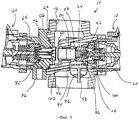
Измерение внутреннего давления для вспомогательного устройства обеспечивается регулирующим клапаном, сконфигурированным для управления потоком жидкости для более точной индикации давления на выходе 18. Благодаря доведению жидкости до требуемого состояния жидкость быстро преобразуется из турбулентного режима потока в ламинарный поток с целью обеспечения более точной индикации выходного давления. В одном из примеров режима потока, показанном на фиг.3, регулирующий клапан 14 регулятора 10 имеет модифицированный выход 92, настроенный для получения контроля над потоком вспомогательным блоком. Вспомогательный блок контроля потока состоит из сетчатого фильтра 94, который состоит из множества перегородок или ячеечного экрана, полукруглого сита 96 с множеством отверстий и центральной измерительной трубки 98. Внутренний конец измерительной трубки 98 находится в жидкостной связи с внутренней частью привода 12 и внутренней частью контроллера 60 посредством трубок 100, 102 соответственно; окно 86 закрыто с целью предотвращения протечек. Поток жидкости преобразуется из турбулентного режима потока в ламинарный поток, когда жидкость проходит через сетчатый фильтр 94 и сито 96, что приводит к более точному измерению выходного давления в контрольной точке на измерительной трубке 98. Принцип доведения потока до необходимого состояния доказал свою эффективность, однако блок режима потока довольно дорог в производстве. Более того, этот блок требует значительных и дорогостоящих модификаций стандартного корпуса регулятора и не может быть с легкостью изменен под другие размеры корпуса. Таким образом, существует необходимость в разработке внутреннего механизма двойного контроля для привода и вспомогательного устройства в регуляторе давления газа, который был бы менее дорогостоящим в производстве и легко модифицировался под различные размеры регулирующего клапана и типы корпусов.The measurement of the internal pressure for the auxiliary device is provided by a control valve configured to control the fluid flow to more accurately indicate the
Раскрытие изобретенияDisclosure of invention
В одном аспекте изобретение относится к жидкостным регуляторам, которые могут включать в себя регулирующий клапан, имеющий вход, выход и отверстие клапана, расположенное между входом и выходом; привод, связанный с регулирующим клапаном и укомплектованный клапанной тарелкой привода, которая расположена внутри регулирующего клапана и перемещается между закрытым положением, закрывающим выпускную сторону клапанного отверстия, и открытым положением, расположенным удаленно от клапанного отверстия; и вспомогательное устройство, связанное с регулирующим клапаном и настроенное на измерение входного давления и соответствующее реагирование, если полученное входное давление отличается от заданного давления вспомогательного устройства. Жидкостный регулятор далее может состоять из трубки Пито, имеющей первый конец с точкой измерения, расположенной внутри выхода регулирующего клапана, первого патрубка, протянутого по направлению к приводу, и второго патрубка, протянутого в сторону вспомогательного устройства. Первый конец и первый патрубок трубки Пито могут приводить точку измерения и выход в жидкостную связь с внутренней частью привода, а первый конец и второй патрубок трубки Пито могут приводить точку измерения и выход в жидкостную связь с внутренней частью вспомогательного устройства. Привод может быть сконфигурирован так, чтобы двигать клапанную тарелку привода в сторону отверстия клапана, если давление на точке измерения трубки Пито возрастает, и отодвигать клапанную тарелку привода от отверстия клапана, если давление на контрольной точке падает, с целью поддержания давления за жидкостным регулятором приблизительно равным заданному значению давления регулятора, а давление на точке измерения может быть входным давлением на вспомогательном устройстве.In one aspect, the invention relates to fluid controllers, which may include a control valve having an inlet, an outlet, and a valve opening located between the inlet and the outlet; an actuator associated with the control valve and equipped with a valve poppet, which is located inside the control valve and moves between the closed position covering the outlet side of the valve hole and the open position located remotely from the valve hole; and an auxiliary device associated with the control valve and configured to measure the input pressure and the corresponding response if the received input pressure is different from the set pressure of the auxiliary device. The liquid regulator may further consist of a pitot tube having a first end with a measuring point located inside the outlet of the control valve, a first nozzle extended towards the actuator, and a second nozzle extended towards the auxiliary device. The first end and the first nozzle of the pitot tube can bring the measuring point and outlet into fluid communication with the inside of the drive, and the first end and the second nozzle of the pitot tube can bring the measurement point and outlet into fluid communication with the inside of the auxiliary device. The actuator can be configured to move the actuator poppet toward the valve opening if the pressure at the measuring point of the Pitot tube rises and move the actuator poppet away from the valve opening if the pressure at the set point drops to approximately equal the pressure behind the fluid regulator the set pressure of the regulator, and the pressure at the measuring point may be the input pressure on the auxiliary device.
В другом аспекте изобретение относится к жидкостным регуляторам, которые могут быть оснащены регулирующим клапаном, имеющим вход, выход и отверстие клапана, расположенное между входом и выходом; привод, связанный с регулирующим клапаном и укомплектованный клапанной тарелкой привода, которая расположена внутри регулирующего клапана и перемещается между закрытым положением, закрывающим выпускную сторону клапанного отверстия, и открытым положением, расположенным удаленно от клапанного отверстия; и вспомогательное устройство, связанное с регулирующим клапаном и настроенное таким образом, чтобы измерять входное давление и производить соответствующие действия, если полученное входное давление отличается от заданного давления вспомогательного устройства. Жидкостный регулятор далее может состоять из трубки Пито, имеющей первый конец с точкой измерения, расположенной внутри выхода регулирующего клапана, первого патрубка, протянутого по направлению к приводу, и второго патрубка, протянутого в сторону вспомогательного устройства. Первый конец и первый патрубок трубки Пито могут приводить точку измерения и выход в жидкостную связь с внутренней частью привода, а первый конец и второй патрубок трубки Пито могут приводить точку измерения и выход в жидкостную связь с внутренней частью вспомогательного устройства. Привод может быть сконфигурирован так, чтобы двигать клапанную тарелку привода в сторону отверстия клапана, если давление на точке измерения трубки Пито возрастает, и отодвигать клапанную тарелку привода от отверстия клапана, если давление на точке измерения падает с целью поддержания давления за жидкостным регулятором приблизительно равным заданному значению давления регулятора, а давление на точке измерения может быть входным давлением на вспомогательном устройстве.In another aspect, the invention relates to fluid controllers that may be equipped with a control valve having an inlet, an outlet, and a valve opening located between the inlet and the outlet; an actuator associated with the control valve and equipped with a valve poppet, which is located inside the control valve and moves between the closed position covering the outlet side of the valve hole and the open position located remotely from the valve hole; and an auxiliary device associated with the control valve and configured so as to measure the inlet pressure and take appropriate action if the received inlet pressure is different from the set pressure of the auxiliary device. The liquid regulator may further consist of a pitot tube having a first end with a measuring point located inside the outlet of the control valve, a first nozzle extended towards the actuator, and a second nozzle extended towards the auxiliary device. The first end and the first nozzle of the pitot tube can bring the measuring point and outlet into fluid communication with the inside of the drive, and the first end and the second nozzle of the pitot tube can bring the measurement point and outlet into fluid communication with the inside of the auxiliary device. The actuator can be configured to move the actuator valve disc toward the valve opening if the pressure at the measuring point of the pitot tube rises and move the actuator disc from the valve opening if the pressure at the measuring point drops to maintain the pressure behind the fluid regulator approximately equal to the set the pressure of the regulator, and the pressure at the measuring point may be the input pressure on the auxiliary device.
В еще одном аспекте изобретение относится к механизмам двойного контроля для жидкостных регуляторов, которые могут быть оснащены регулирующим клапаном, имеющим вход, выход и отверстие клапана, расположенное между входом и выходом; привод, связанный с регулирующим клапаном и укомплектованный клапанной тарелкой привода, которая расположена внутри регулирующего клапана и перемещается между закрытым положением, закрывающим выпускную сторону клапанного отверстия, и открытым положением, расположенным удаленно от клапанного отверстия; и вспомогательное устройство, связанное с регулирующим клапаном и настроенное таким образом, чтобы измерять входное давление и производить соответствующие действия, если полученное входное давление отличается от заданного давления вспомогательного устройства. Механизм двойного контроля может содержать трубку Пито, имеющую первый конец с точкой измерения, расположенной внутри выхода регулирующего клапана, первый патрубок, протянутый из трубки Пито по направлению к приводу, при этом трубка Пито и первый патрубок приводят точку измерения и выход в жидкостную связь с внутренней частью привода; второй патрубок, протянутый из трубки Пито по направлению к вспомогательному устройству, при этом трубка Пито и второй патрубок трубки Пито приводят точку измерения и выход в жидкостную связь с внутренней частью вспомогательного устройства. Привод может быть сконфигурирован так, чтобы двигать клапанную тарелку привода в сторону отверстия клапана, если давление на точке измерения трубки Пито возрастает, и отодвигать клапанную тарелку привода от отверстия клапана, если давление на точке измерения падает с целью поддержания давления за жидкостным регулятором приблизительно равным заданному давлению регулятора, а давление на точке измерения может быть входным давлением на вспомогательном устройстве.In yet another aspect, the invention relates to dual control mechanisms for fluid controllers, which may be equipped with a control valve having an inlet, an outlet, and a valve opening located between the inlet and the outlet; an actuator associated with the control valve and equipped with a valve poppet, which is located inside the control valve and moves between the closed position covering the outlet side of the valve hole and the open position located remotely from the valve hole; and an auxiliary device associated with the control valve and configured so as to measure the inlet pressure and take appropriate action if the received inlet pressure is different from the set pressure of the auxiliary device. The dual control mechanism may include a pitot tube having a first end with a measuring point located inside the outlet of the control valve, a first nozzle extended from the pitot tube toward the actuator, while the pitot tube and the first nozzle bring the measurement point and exit into fluid communication with the internal part of the drive; a second pipe extending from the pitot tube towards the auxiliary device, while the pitot tube and the second pipe of the pitot tube lead to the measuring point and exit into fluid communication with the inside of the auxiliary device. The actuator can be configured to move the actuator poppet toward the valve opening if the pressure at the measuring point of the pitot tube rises and move the actuator poppet away from the valve opening if the pressure at the measuring point drops to keep the pressure behind the fluid regulator approximately equal to the set the pressure of the regulator, and the pressure at the measuring point may be the input pressure at the auxiliary device.
Дополнительные аспекты изобретения определены в формуле изобретения данного патента.Additional aspects of the invention are defined in the claims of this patent.
Краткое описание чертежейBrief Description of the Drawings
На фиг.1 изображен регулятор давления газа в боковом поперечном сечении в закрытом положении, с приводом и контроллером избыточного давления.Figure 1 shows a gas pressure regulator in a lateral cross section in the closed position, with a drive and an overpressure controller.
Фиг.2 - регулятор давления газа в боковом поперечном сечении, изображенный на фиг.1, в полностью открытом положении.Figure 2 - gas pressure regulator in a lateral cross section, shown in figure 1, in a fully open position.
Фиг.3 - регулятор давления газа в боковом поперечном сечении, со вспомогательным блоком контроля потока, в полностью открытом положении.Figure 3 - gas pressure regulator in a lateral cross section, with an auxiliary flow control unit, in the fully open position.
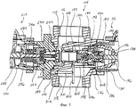
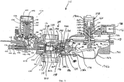
На фиг.4 показан регулятор давления газа в боковом поперечном сечении, с двойной индикацией давления для привода и контроллера избыточного давления, в соответствии с данным описанием, в закрытом положении.Figure 4 shows the gas pressure regulator in a lateral cross-section, with a double pressure indication for the actuator and controller overpressure, in accordance with this description, in the closed position.
Фиг.5 - регулирующий клапан регулятора давления газа, изображенного на фиг.4, в боковом поперечном сечении.Figure 5 - control valve of the gas pressure regulator shown in figure 4, in a lateral cross section.
На фиг.6 показан регулятор давления газа в боковом поперечном сечении, с двойной индикацией давления для привода и предохранительного запорного механизма, в соответствии с данным описанием; предохранительный запорный механизм находится в закрытой позиции.Figure 6 shows the gas pressure regulator in a lateral cross section, with a double pressure indication for the actuator and safety locking mechanism, in accordance with this description; safety locking mechanism is in the closed position.
Фиг.7 - чертеж со вскрытием внутренней части верхней обшивки предохранительного запорного механизма, показанного на фиг.6.Fig.7 is a drawing with the opening of the inner part of the upper casing of the safety locking mechanism shown in Fig.6.
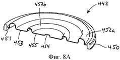
Фиг.8А - вид мембраны в разрезе, расположенной между верхней обшивкой и корпусом клапана предохранительного запорного механизма, изображенного на фиг.6.Fig. 8A is a sectional view of the membrane located between the upper casing and the valve body of the safety locking mechanism shown in Fig. 6.
Фиг.8В - вид мембраны, изображенной на фиг.8А, в разрезе, в конфигурации, работающей при низком давлении.8B is a cross-sectional view of the membrane of FIG. 8A in a configuration operating at low pressure.
Фиг.8С - вид мембраны, изображенной на фиг.8А, в разрезе, в конфигурации, работающей при высоком давлении.FIG. 8C is a cross-sectional view of the membrane of FIG. 8A in a high pressure configuration.
Фиг.9А представляет собой вид в вертикальном разрезе блока клапанов предохранительного запорного механизма, изображенного на фиг.6, с выделенным возвратным валиком в положении возврата.Fig. 9A is a vertical sectional view of the valve block of the safety locking mechanism of Fig. 6, with the return roller highlighted in the return position.
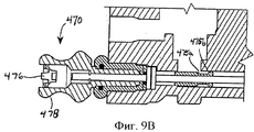
На фиг.9В показан вид в вертикальном разрезе блока клапанов предохранительного запорного механизма, изображенного на фиг.6, с выделенным возвратным валиком в обратном запертом положении.FIG. 9B is a vertical sectional view of the valve block of the safety locking mechanism of FIG. 6, with the return roller highlighted in the reverse locked position.
Осуществление изобретенияThe implementation of the invention
Хотя приведенный ниже текст содержит подробное описание множества различных вариантов осуществления изобретения, нужно понимать, что законную силу имеет объем изобретения, определенный в формуле изобретения, приведенной в конце этого патента. Следует понимать, что подробное описание изобретения содержит только примеры, а не все возможные варианты воплощения данного изобретения, так как описание всех возможных вариантов было бы если не невозможным, то, по крайней мере, практически нецелесообразным. Многочисленные альтернативные варианты осуществления настоящего изобретения, которые могли бы реализовываться с помощью существующих технологий или технологий, которые будут разработаны после даты подачи этой заявки на патент, все равно попадают в объем притязаний, определенный формулой данного изобретения.Although the text below contains a detailed description of many different embodiments of the invention, it should be understood that the scope of the invention defined in the claims at the end of this patent has legal force. It should be understood that a detailed description of the invention contains only examples, and not all possible embodiments of the present invention, since a description of all possible options would be, if not impossible, then at least practically impractical. Numerous alternative embodiments of the present invention, which could be implemented using existing technologies or technologies that will be developed after the filing date of this patent application, still fall within the scope of the claims defined by the claims of this invention.
Также нужно понимать, что, за исключением случаев, когда термин определен в настоящем патенте в явной форме с использованием фразы «Для целей настоящей заявки термин '__' используется в следующем значении…» или подобной фразы, значение такого термина не ограничивается, ни явно, ни косвенно, простым и обыкновенным значением, и значение такого термина не должно ограничиваться каким-либо утверждением, приведенным в любом разделе этого описания изобретения (кроме формулы изобретения). Термины, перечисленные в формуле изобретения в конце этого документа, упоминаются в описании изобретения каждый в своем единственном значении лишь для ясности, чтобы не запутать читателя, и не предполагается, что такие термины, перечисленные в формуле изобретения, должны ограничиваться (подразумеваемым или иным образом) таким единственным значением. Наконец, за исключением случаев, когда элемент формулы изобретения определен упоминанием слова "означает" и функцией без описания какой-либо структуры, не предполагается интерпретировать полное значение какого-либо элемента формулы изобретения на основании использования Свода законов США, раздел 35, §112, шестой абзац.It should also be understood that, unless the term is explicitly defined in this patent using the phrase "For the purposes of this application, the term '__' is used in the following sense ..." or a similar phrase, the meaning of such a term is not limited, nor explicitly, nor indirectly, by a simple and ordinary meaning, and the meaning of such a term should not be limited to any statement given in any section of this description of the invention (except for the claims). The terms listed in the claims at the end of this document are mentioned in the description of the invention each in its sole meaning for clarity, so as not to confuse the reader, and it is not intended that such terms listed in the claims be limited (implied or otherwise) such a single meaning. Finally, unless the element of the claims is defined by the word “means” and by a function without describing any structure, it is not intended to interpret the full meaning of any element of the claims based on the use of the United States Code, section 35, §112, sixth paragraph.
На фиг.4 и 5 изображен регулятор давления газа 110, сконструированный в соответствии с одним вариантом осуществления настоящего изобретения. Данный регулятор давления газа 110 состоит, главным образом, из привода 112 и регулирующего клапана 114. Регулирующий клапан 114 имеет вход 116, куда поступает газ, например, из газораспределительной системы, и выход 118 для доставки газа, например, к объекту, имеющему один или более газовых приборов. Привод 112 соединен с регулирующим клапаном 114 и имеет узел управления 120 с таким управляющим элементом, как клапанная тарелка 122. В условиях так называемого первого или нормального режима эксплуатации, узел управления 120 измеряет давление на выходе 118 регулирующего клапана 114, т.е. выпускное давление, и управляет положением клапанной тарелки 122 так, чтобы выпускное давление было приблизительно равным заранее определенному заданному значению - контрольному значению давления. Кроме того, в случаях возникновения неполадок в системе, регулятор 110 выполняет предохранительную функцию, которая в целом соответствует предохранительной функции, описанной выше со ссылкой на регулятор 10, изображенный на фиг.1 и 2.Figures 4 and 5 show a
Далее, с отсылкой на фиг.4, регулирующий клапан 114 определяет размер соединительной части 124 и отверстия клапана 126. Соединительная часть 124 расположена между входом 116 и выходом 118 с клапанным отверстием 128. Для перемещения между входом 116 и выходом 118 газ должен пройти через клапанное отверстие 128 регулирующего клапана 114. Клапанное отверстие 128 можно извлечь из регулирующего клапана 114 и заменить другим клапанным отверстием, имеющим другой внутренний диаметр или конфигурацию трубы, для соответствия параметрам потока и эксплуатационным характеристикам регулирующего клапана 114 для конкретной области применения. В описываемой модификации отверстие клапана 126 определяет размер отверстия, расположенного вдоль оси, перпендикулярной оси входа 116 и выхода 118 регулирующего клапана 114.Further, with reference to FIG. 4, the
Привод 112 состоит из корпуса 130 и узла управления 120, как уже упоминалось выше. Корпус 130 состоит из верхней части корпуса 130а и нижней части корпуса 130b, скрепленных между собой, например, множеством скоб. Нижняя часть корпуса 130b изменяет размер контрольной полости 132 и отверстия привода 134. Отверстие привода 134 соединено с отверстием 126 регулирующего клапана 114 для обеспечения жидкостной связи между приводом 112 и регулирующим клапаном 114. Верхняя часть корпуса 130а изменяет размер предохранительной полости 136 и выпускного отверстия 138. Кроме того, верхняя часть корпуса 130а имеет элемент башенного типа 140, в котором находится элемент узла управления 120, назначение которого будет описано ниже.The
Узел управления 120 состоит из мембранного узла 142, диска и балансировочного узла 144, а также выпускного клапана 146. Мембранный узел 142 состоит из мембраны 148, поршня 150, регулирующей пружины 152, уравновешивающей пружины 154, гнезда комбинированной пружины 156, гнезда уравновешивающей пружины 158, гнезда пружины регулятора 160 и направляющей поршня 162.The
В частности, мембрана 148 состоит из мембраны круглой формы, определяющей размер отверстия соответствующей центральной части. Мембрана 148 сделана из гибкого, практически воздухонепроницаемого материала, ее край плотно закреплен между верхней 130а и нижней 130b частями корпуса 130. Таким образом, мембрана 148 отделяет предохранительное отверстие 136 от контрольной полости 132.In particular, the
Гнездо комбинированной пружины 156 расположено на верху мембраны 148 и образует отверстие, расположенное коаксиально относительно мембраны 148. Как изображено на фиг.4, гнездо комбинированной пружины 156 поддерживает регулирующую пружину 152 и уравновешивающую пружину 154.The
Поршень 150 в изложенном варианте реализации изобретения включает обычно продолговатую стержнеобразную деталь, имеющую часть уплотнительной манжеты 164, хомут 166, резьбовую часть 168 и направляющую часть 170. Часть уплотнительной манжеты 164 является вогнутой и, в целом, имеет форму диска, и продолжается по окружности до средней части поршня 150, и расположена чуть ниже мембраны 148. Хомут 166 включает полость, соответствующую размерам соединительной муфты 172, соединенной с диском и балансировочным узлом 144, который обеспечивает соединение между узлом мембраны 142 и диском и балансировочным узлом 144, как будет описано далее.The
Направляющая часть 170 и резьбовая часть 168 поршня 150 проходят через отверстия в мембране 148 и гнезде комбинированной пружины 156 соответственно. Направляющая часть 170 поршня 150 подвижно располагается в полости направляющей поршня 162, которая обеспечивает осевое центрирование поршня 150 и оставшейся части узла управления 120. Уравновешивающая пружина 154, гнездо уравновешивающей пружины 158 и муфта 174 расположены на резьбовой части 170 поршня 150. Муфта 174 удерживает уравновешивающую пружину 154 между гнездом комбинированной пружины 156 и гнездом уравновешивающей пружины 158. Регулирующая пружина 152 расположена в верхней части гнезда комбинированной пружины 156, как было упомянуто, и в башенной части 140 верхнего элемента 130а корпуса. Гнездо регулирующей пружины 160 ввинчивается в башенную часть 140 и прижимает регулирующую пружину 152 вплотную к гнезду комбинированной пружины 156. В представленном варианте реализации изобретения регулирующая пружина 152 и уравновешивающая пружина 154 включают в себя цилиндрические пружины сжатия. Таким образом, регулирующая пружина 152 устанавливается против верхнего элемента корпуса 130а и прикладывает направленную вниз силу к гнезду комбинированной пружины 156 и к мембране 148. Уравновешивающая пружина 154 устанавливается против гнезда комбинированной пружины 156 и прилагает направленную вверх силу к гнезду уравновешивающей пружины 158, которая, в свою очередь, прилагает силу к поршню 150. В представленном варианте реализации изобретения, силу, образованную регулирующей пружиной 152, можно регулировать путем изменения положения гнезда регулирующей пружины 160 в башенной части 140 и, таким образом, контролировать давление в регуляторе 110.The
Регулирующая пружина 152 противодействует давлению в контрольной полости 132, которое измеряется мембраной 148. Как уже было отмечено, это давление равно давлению на выходе 118 регулирующего клапана 114. Соответственно, сила, создаваемая регулирующей пружиной 152, устанавливает давление в выходном отверстии в соответствии с заданным значением или в соответствии с контрольным давлением для регулятора 110. Узел 142 мембраны функционально соединяется с диском и балансировочным узлом 144, как упомянуто выше, через хомут 166 поршня 150 и соединительную муфту 172, и посредством рукоятки управления 176.The
Диск и балансировочный узел 144 включает шток привода 178, который приводится в действие рукояткой управления 176 и приводит в движение клапанную тарелку 122, перемещающуюся из открытого положения в закрытое и обратно, при сгибании мембраны 148 под влиянием изменения выходного давления. В частности, шток привода 178, как правило, представляет собой длинный стержень, торцевая поверхность которого соединена с рукояткой управления 176. Рукоятка управления 176 представляет собой слегка искривленный стержень с опорной точкой 176а и свободным концом 176b. Опорная точка 176а шарнирно соединена с нижней частью корпуса 130b и включает палец 180, имеющий скругленный конец и сцепляющийся с торцевой поверхностью штока привода 178. Свободный конец 176b расположен между верхней частью и стержнем соединительной муфты 172, которая соединена с хомутом 166 поршня 150. Таким образом, соединительная муфта 172 и рукоятка управления 176 функционально соединяют диск и балансировочный узел 144 с узлом мембраны 142.The disk and balancing assembly 144 includes a
Клапанная тарелка 122 диска и балансировочного узла 144 функционально соединяется со штоком привода 178 и содержит герметизирующую вставку 182, которая соединяется с выходом клапанного отверстия 128 и перекрывает поток жидкости через регулирующий клапан 114. Клапанная тарелка 122 соединяется со штоком привода 178 через отверстие регулирующего штока 184 и гнезда 186 балансировочной пружины, эти элементы осуществляют прямолинейное движение при помощи направляющей штока 188, стопорной планки 190, стопорного кольца регулирующей мембраны 192 и корпуса регулирующего канала 194. Направляющая штока 188 без зазора входит во входное отверстие привода 134 и состоит из цилиндрической внутренней части, которая удерживает шток привода 178. Направляющая штока 188, кроме того, включает каналы 196, посредством которых создается участок пути, помещающий выход 118 в жидкостную связь с контрольной полостью 132, как будет показано ниже.The
Направляющая штока 188 сцепляется со стопорной планкой 190, которая расположена между направляющей штока 188 и корпусом балансировочного канала 194, чтобы удерживать стопорную планку 190 и корпус балансировочного канала 194 на месте во входном отверстии клапана 126. Стопорная планка 190 обычно бывает круглой и включает центральное отверстие, через которое проходит шток балансировочного канала 184. Корпус регулирующего канала 194, как правило, цилиндрической формы и полый, он доходит до клапанного отверстия 128 и имеет внутренний диаметр, соответствующий размеру клапанной тарелки 122. Стопорное кольцо мембраны 206 расположено в пределах корпуса регулирующего канала 194 и отверстия стопорной планки 190 и удерживается на месте между поверхностью стопорной планки 190 и внутренним краем корпуса регулирующего канала 194. В пределах корпуса регулирующего канала 194 предусматривается регулирующая мембрана 198 в форме диска, с отверстием в центре. Регулирующая мембрана 198 сделана из гибкого, практически воздухонепроницаемого материала, и ее внешняя поверхность закрепляется между стопорным кольцом регулируюущей мембраны 192 и корпусом регулирующего канала 194. Внутренняя грань центрального отверстия регулирующей мембраны 198 плотно закреплена между клапанной тарелкой 122 и штоком регулирующего канала 184. Клапанная тарелка 122, шток регулирующего канала 184 и шток привода 178 смещаются в сторону открытого положения регулирующего клапана 114 при помощи балансировочной пружины 200, расположенной между гнездом пружины 186 и опорной поверхностью стопорного кольца мембраны 192.The
Регулирующая мембрана 198 передает усилие на клапанную тарелку 122 в направлении клапанного отверстия 128, чтобы компенсировать давление на клапанную тарелку 122, создаваемое входным давлением жидкости, проходящей через клапанное отверстие 128. Клапанная тарелка 122, шток регулирующего канала 184 и стопорное кольцо мембраны 192 сконфигурированы для создания канала, за счет обеспечения жидкостной связи поверхности регулирующей мембраны 198 напротив клапанного отверстия 128 со входным давлением, воздействующим на клапанную тарелку 122. Компоненты диска и регулирующего узла 144 настроены так, чтобы усилие, направленное на регулирующую мембрану 198, было противоположно и приблизительно равно силе входного давления на клапанную тарелку 122. Это делается для того, чтобы устранить любое воздействие входного давления на узел мембраны 142 и, тем самым, обеспечить более точное регулирование выходного давления регулятором давления газа 110.The
В приведенном варианте реализации изобретения регулятор давления газа 110 включает в себя также вспомогательное устройство в виде устройства контроля избыточного давления 212, которое перекрывает поток жидкости через регулирующий клапан 114 в случае возникновения избыточного давления, пока выходное давление не нормализуется после сбоя привода 112. Контроллер избыточного давления 212 в приведенном варианте реализации изобретения имеет конфигурацию, подобную конфигурации привода 112, при этом используется аналогичнная нумерация, только первая цифра «1» заменяется на цифру «2» для соответствующих элементов контроллера избыточного давления 212. Контроллер избыточного давления 212 действует так же, как привод 112, с соответствующими отличиями, которые будут рассмотрены далее в данном документе.In the illustrated embodiment, the
Так как контроллер 212 реагирует только в случае, когда выходное давление превышает давление отсечки, установленное мембраной 248 и регулирующей пружиной 252, узел контрольной мембраны 242 и регулирующий узел 244 настраиваются соответствующим образом. Балансировочная пружина 300, расположенная между гнездом пружины 286 и стопорным кольцом мембраны 292, смещает клапанную тарелку 222 в нормальное открытое положение, как показано на фиг.4 и 5. Соединительная муфта 272 и рукоятка управления 276 настроены так, чтобы соединительная муфта 272 направляла рукоятку управления 276 в нужном направлении для смещения клапанной тарелки 222 в закрытое положение и до ее совмещения с входной стороной клапанного отверстия 128, чтобы перекрыть поток жидкости через регулирующий клапан 114. Штифт 272а соединительной муфты 272 соединяется со свободным концом 276b рукоятки управления 276, что обеспечивает вращение рукоятки управления 276, когда мембрана 248 и поршень 250 движутся вверх под действием выходного давления, превышающего давление отсечки. И наоборот, верхняя часть 272а соединительной муфты 272 располагается на расстоянии от рукоятки управления 276, таким образом, нисходящее движение мембраны 248 и поршня 250, вызванное понижением выходного давления, не приводит к перемещению рукоятки управления 276. Конечно, специалистам в данной области техники известны альтернативные конфигурации устройств контроля избыточного давления, включая такие, которые настроены на срабатывание при падении выходного давления ниже нижней границы давления отсечки. Изобретатели считают, что данные конфигурации, используемые в регуляторах газового давления, попадают в сферу действия настоящего изобретения.Since the
Конфигурация диска и регулирующего узла 244 отличается, но он функционирует так же, как и узел 144 привода 112. Входное отверстие контроллера и корпус регулирующего канала объединены в соединительном модуле 294, который соединяет контроллер 212 со вторым входным отверстием 226 регулирующего клапана 114, расположенного напротив привода 112, и на входе клапанного отверстия 128. Внутренний диаметр модуля 294 соответствует размеру клапанной тарелки 222. Регулирующая мембрана 298 закреплена между стопорным кольцом мембраны 292 и корпусом регулирующего канала 294 на внешней границе, а внутренняя граница центрального отверстия регулирующей мембраны 298 плотно закреплена между клапанной тарелкой 222 и штоком 284. Клапанная тарелка 222, шток регулирующего канала 284 и стопорное кольцо мембраны 292 настроены для обеспечения прохода, помещая регулирующую мембрану 298 напротив клапанного отверстия 128 в жидкостную связь, при этом входное давление на клапанную тарелку 222 уравновешивает усилие, применяемое к клапанной тарелке 222 входным давлением.The configuration of the disk and the control unit 244 is different, but it functions in the same way as the node 144 of the
Контроллер 212, изображенный на фиг.4 и 5, является модификацией контроллера 60, показанного на фиг.1 и 2, что должно облегчить двойной контроль выходного давления, как в приводе 112, так и в контроллере 212, при помощи измерения давления в регуляторе давления газа на выходе 118. Отверстие 86, куда поступает трубопровод обратной связи выходного давления 84, можно исключить, таким образом, внешний трубопровод обратной связи 84 больше не требуется. В этом варианте реализации изобретения трубка Пито 302 с контрольной точкой на выходе 118 регулирующего клапана 114 обеспечивает обратную связь выходного давления как для привода 112, так и для контроллера избыточного давления 212. Трубка Пито 302 проходит внутри устройства до клапанного отверстия 128 с первым патрубком 304, отходящим от основной ветви трубки Пито 302 во входное отверстие клапана 126. Патрубок 304 привода проходит через отверстия 306, 308 (см. фиг.5) через корпус регулирующего канала 194 и стопорную планку 190 соответственно. Выходное давление, пройдя через патрубок привода 304 и через отверстия 306 и 308, передается по каналам 196 в контрольную полость 132.The
В дополнение к патрубку привода 304, от трубки Пито 302 отходит второй патрубок 310 и идет в направлении контроллера избыточного давления 212. В проиллюстрированном варианте реализации изобретения ветвь контроллера 310 идет до прохода или канала 312 через стенку регулирующего клапана 114, непосредственно у выхода 118. Канал регулирующего клапана 312 проходит через стенку регулирующего клапана 114 и соединяется с внешним отверстием соответствующего прохода или канала 314 через стенку соединительного модуля 294. Проход соединительного модуля 314 аналогичным образом проходит через стенку соединительного модуля 294 и за пределы корпуса контроллера 230. Выходное давление, пройдя через патрубок контроллера 310 и проходы 312 и 314, передается через диск и регулирующий узел 244 в контрольную полость 232 контроллера 214.In addition to the
В условиях роста операционного спроса в газораспределительной системе, например, когда пользователь начинает использовать прибор, такой как печь, кухонную плиту и так далее, газ поступает в такой прибор из выхода 118 и, соответственно, контрольной полости 132 привода 112 и контрольной полости 232 контроллера 212, тем самым уменьшая давление, измеряемое мембранами 148, 248. При уменьшении давления на мембране 148, возникает дисбаланс между силой регулирующей пружины и силой выходного давления на мембране 148, в результате, регулирующая пружина 152 растягивается и смещает мембрану 148 и поршень 150 вниз относительно корпуса 130. Это заставляет рукоятку управления 176 вращаться по часовой стрелке, что, в свою очередь, вращает палец 180 относительно поверхности штока привода 178. Таким образом, шток 178 и клапанная тарелка 122 отодвигаются от выхода 124 клапанного отверстия 128 под воздействием балансирующей пружины 200 и открывают регулирующий клапан 114. В то же время, уменьшение давления может также привести к дисбалансу между силой регулирующей пружины и силой выпускного давления на мембране 248, в результате регулирующая пружина 252 растягивается и смещает диафрагму 248 и поршень 250 вниз относительно корпуса 230. Но, так как верхняя часть соединительной муфты 272 расположена далеко от рукоятки управления 276, контроллер 212 не реагирует аналогичным образом на падение давления с движением клапанной тарелки 222.In the context of growing operational demand in the gas distribution system, for example, when the user begins to use a device such as a stove, stove and so on, gas enters such a device from the
Когда спрос в газораспределительной системе падает, например, когда пользователь выключает свои газовые приборы, регулятор давления газа 110 изначально реагирует уменьшением потока жидкости через регулирующий клапан 114. Так как газ продолжает поступать через клапанное отверстие 128 в нижестоящие элементы системы, давление на выходе 118 возрастает, равно как и в контрольной полости 132 привода 112 и контрольной полости 232 контроллера 212. Так как давление на мембране 148 увеличивается и превосходит силу регулирующей пружины, мембрана 148 и поршень 150 поднимаются вверх относительно корпуса 130. Движение вверх заставляет рукоятку управления 176 вращаться против часовой стрелки, что, в свою очередь, перемещает шток привода 178 и клапанную тарелку 122 по направлению к клапанному отверстию 128, сокращая поток жидкости через регулирующий клапан 114. При нормальных условиях, выпускное давление будет падать приблизительно до значения, установленного на приводе и будет поддерживаться на таком уровне, пока спрос в нижестоящих элементах ситсемы не приведет к соответствующей реакции привода 112.When the demand in the gas distribution system falls, for example, when the user turns off their gas appliances, the
Давление отсечки на контроллере выше, чем давление, установленное на приводе, и, как правило, контроллер 212 не реагирует на изменения давления в нормальном рабочем диапазоне регулятора давления газа 110. В случае выхода из строя привода 112, например разрыва мембраны 148, клапанная тарелка 122 может оставаться открытой несмотря на рост выходного давления выше установленного на приводе. В конце концов, давление в точке измерения трубки Пито 302 достигает уровня давления отсечки контроллера 212. Выходное давление передается в контрольную полость 232 через патрубок контроллера 310, что приводит к дисбалансу между силой регулирующей пружины и силой выпускного давления мембраны 248, в итоге, регулирующая пружина 252 сокращается и смещает мембрану 248 и поршень 250 вверх относительно корпуса 230. При движении поршня 250, штифт 272а соединительной муфты 272 поворачивает рукоятку управления 276, что приводит в движение привод 278 и смещает клапанную тарелку 222 до совмещения с клапанным отверстием 128, тем самым перекрывая поток жидкости через регулирующий клапан 114. Контроллер 212 не будет пропускать поток жидкости до тех пор, пока давление в точке измерения трубки Пито 302 превышает давление отсечки контроллера.The cutoff pressure on the controller is higher than the pressure set on the actuator, and, as a rule, the
Если клапанная тарелка 122 не закрывает выход 124 клапанного отверстия 128, газ поступает во вторую часть 236 корпуса регулирующего канала 194. Вследствие настройки внутренней поверхности второй части 236, клапанной тарелки 122 и отверстия 242, жидкость выталкивается через отверстие 242 и расположенные там перегородки 244 с незначительным отклонением от пути потока. При прохождении жидкости через перегородки 244, турбулентный поток жидкости, в той степени, в которой присутствует турбулентность, преобразуется в ламинарный поток. Соответственно, когда жидкость достигает выхода 118 регулирующего клапана 114 и точки измерения трубки Пито 302, плавный поток жидкости позволяет лучше измерить выходное давление и, соответственно, лучше регулировать такое выходное давление с помощью узла управления 120.If the
Как уже отмечалось, контроллер 212 - это лишь один из множества вариантов вспомогательных устройств, которые могут использоваться с регуляторами давления газа 110. На фиг.6 показан предохранительный запорный механизм 410, реализованный с регулятором давления газа 110 и настроенный на двойной контроль в соответствии с данным изложением сущности изобретения при помощи трубки Пито 302. Предохранительный запорный механизм в общих чертах похож на устройство, проиллюстрированное и описанное в патенте США №2008/0257420, который включен в настоящий документ путем ссылки. Предохранительный запорный механизм 410 можно устанавливать на регулирующий клапан 114 с входной стороны клапанного отверстия 128 на основном регуляторе давления газа 110. Предохранительный запорный механизм 410 состоит из блока клапанов 412, верхнего кожуха 414, присоединенного к блоку клапанов, фланца стопорного кольца 416, установленного на одной стороне блока клапанов 412, концевого выключателя 418 и штифта сброса 420, идущего от блока клапанов. Предохранительный запорный механизм 410 также присоединяется к регулирующему клапану 114 крепежными элементами 422. Аналогично, верхний кожух 414 присоединен к блоку клапанов 412 крепежными элементами 426. В качестве крепежных элементов 422 и 426 могут использоваться болты, заклепки, винты или практически любой тип крепежа, пригодный для соединения одного элемента к другому.As already noted, the
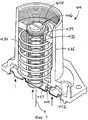
Верхний кожух 414 (фиг.7) содержит в себе пружину избыточного давления 430 и пружину пониженного давления 432. Пружина пониженного давления 432 определяет нижнее (минимальное) допустимое давление газа в газораспределительной системе. Аналогично, пружина избыточного давления 430 определяет верхнее (максимальное) допустимое давление газа в газораспределительной системе. Обе пружины - 430 повышенного давления и 432 пониженного давления - соосно располагаются внутри верхнего кожуха 414 (т.е. центральные оси обеих пружин совмещены). Однако соосное расположение пружин не является обязательным, оси пружин могут быть смещены относительно друг друга. Внутренняя литниковая трубка 434 отделяет пружину избыточного давления 430 от пружины пониженного давления 432. Между тем, пружина избыточного давления 430 находится внутри внешней литниковой трубки, которая защищает обе пружины - 430 и 432 - от вредных воздействий окружающей среды. Пружина пониженного давления 432 на одном конце соединена с пластиной мембраны 437, а пружина избыточного давления на одном конце соединена с кольцом избыточного давления 441. Кольцо избыточного давления 441 может соединяться с пластиной мембраны 437. И пластина мембраны 437, и кольцо избыточного давления 441 могут соединяться с мембраной 442, что будет рассмотрено подробнее ниже. Мембрана 442 с одной стороны подвергается воздействию давления в системе, как будет показано ниже, а с другой стороны мембрана 442 подвергается воздействию сил пружин избыточного давления 430 и пониженного давления 432. Часть мембраны 442 является подвижной и может смещаться во внутреннюю часть блока клапанов 412 или верхнего кожуха 414, в зависимости от системного давления вдоль оси А. Ось А по существу параллельна или даже соосна центральным осям пружины избыточного давления 430 и пружины пониженного давления 432.The upper casing 414 (Fig. 7) contains an
На концах, противоположных мембране 442, пружина избыточного давления 430 и пружина пониженного давления 432 соприкасаются с крышкой регулирования избыточного давления 444 и крышкой регулирования пониженного давления 446 соответственно. Крышка регулирования избыточного давления 444 и крышка регулирования пониженного давления 446 смещаются вдоль оси А в обоих направлениях относительно мембраны 442. В одном варианте реализации изобретения крышка регулирования избыточного давления 444 и крышка регулирования пониженного давления 446 могут соединяться резьбой с внешней литниковой трубкой 436 и внутренней литниковой трубкой 434 соответственно. В частности, крышка регулирования избыточного давления 444 может соединяться резьбой с внутренней поверхностью внешней литниковой трубки 436 или с внешней поверхностью внутренней литниковой трубки 434. Крышка регулирования пониженного давления 446 может соединяться резьбой с внутренней поверхностью внутренней литниковой трубки 434. Как крышка 446, так и крышка 444 могут перемещаться вдоль оси А для регулирования натяжения пружины избыточного давления 430 и пружины пониженного давления 432 на пластине мембраны 437. Расстояние между крышками 444 и 446 и пластиной мембраны 437 определяет заданные значения избыточного давления и пониженного давления для предохранительного быстродействующего запорного клапана 410. Размещение обоих пружин - пружины избыточного давления 430 и пружины пониженного давления 432 - на одной стороне мембраны 442 облегчает регулирование как пружины избыточного давления 430, так и пружины пониженного давления 432 за пределами клапана. Пружины 430 и 432 могут регулироваться независимо друг от друга.At the ends opposite the
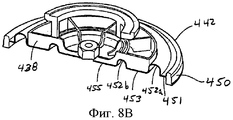
Мембрана 442 (фиг.8А, 8В, 8С) включает внешнее уплотнительное кольцо 450 для уплотнения верхнего кожуха 414 с блоком клапанов 412. Мембрана 442 также включает первый и второй концентрические витки 452а и 452b. В качестве разделителя уплотнительного кольца 450 и первого витка 452а выступает внешняя плоская область 451. В качестве разделителя первого кольца 452а и второго кольца 452b выступает средняя плоская область 453, а в качестве разделителя второго витка 452b и центрального отверстия 454 выступает внутренняя плоская область 455. Первый и второй витки 452а и 452b позволяют использовать мембрану 442 как для настройки низкого давления, так и для настройки высокого давления. Конфигурация низкого давления показана на фиг.8В, а конфигурация высокого давления - на фиг.8С. В центральное отверстие 454 может вставляться крепежный элемент (например, болт) при соединении мембраны 442 и пластины мембраны 437.Membrane 442 (FIGS. 8A, 8B, 8C) includes an outer o-
Конфигурация низкого давления включает пластину мембраны низкого давления 438, которая представляет собой жесткую пластину, покрывающую внутренний виток 452b, внутреннюю плоскую область 455 и среднюю плоскую область 453 (фиг.8В), оставляя подвижными внешний виток 452а и внешнюю плоскую область 451. Аналогично, конфигурация высокого давления включает пластину мембраны высокого давления 440, которая является жесткой пластиной и покрывает внешний виток 452а, и среднюю плоскую область 453 (фиг.8С), оставляя подвижными внутренний виток 452а, внутреннюю плоскую область 455 и внешнюю плоскую область 451. Таким образом, пластина мембраны низкого давления 438 и пластина мембраны высокого давления 440 определяют, какая часть мембраны 442 остается подвижной, а какая - неподвижной.The low-pressure configuration includes a low-
Вернемся к фиг.6. Блок клапанов 412 включает концевой выключатель 418, соединенный с поворотным кулачком 462, который имеет три рычага 463а, 463b, 463с. Кулачок 462 соединен с мембраной 442 через плунжер 464 на первом рычаге кулачка 463а. Плунжер 464 включает плечо плунжера 465, направленное вниз. Плечо плунжера 465 соединено с кулачком 462 в точке соединения 466 на первом рычаге кулачка 463а, которое отклоняется от оси вращения кулачка 462. Когда плунжер 464 движется вверх под действием избыточного давления, превосходящего силу воздействия пружины избыточного давления 430, кулачок 462 вращается против часовой стрелки (в данном варианте реализации изобретения). Во время вращения кулачка 462, зажим, соединенный с первым рычагом кулачка 463а, освобождается, и быстродействующая задвижка 468 закрывает клапанное отверстие 128, тем самым перекрывая подачу газу в основной регулятор давления газа. При пониженном давлении, при котором сила пружины пониженного давления 432 превосходит давление газа в системе, плунжер 464 движется вниз, заставляя кулачок 462 вращаться по часовой стрелке. После заранее установленного объема вращения, зажим, соединенный с первым рычагом кулачка 463а, освобождается, и быстродействующая задвижка 468 закрывается, перекрывая подачу газа в основной регулятор давления. Движение мембраны 442 сообщается концевому выключателю 418 через вращение кулачка 462, потому что концевой переключатель 418 напрямую связан с кулачком 462 через второй рычаг кулачка 462b, который соединен с мембраной 442 посредством кулачка 462 и плунжера 464. Таким образом, концевой выключатель 418 движется в продольном направлении, реагируя на незначительные изменения давления, обнаруживая движение мембраны 442, даже если узел штифта сброса 470 поврежден.Back to Fig.6. The
Блок клапанов 412 также включает в себя узел штифта сброса 470 для повторной установки зажима в кулачке 462. Узел штифта сброса 470 состоит из стержня сброса 472, задвижки повторного зажима 474, индикатора перемещения 476 (фиг.9А, 9В) и рукава сброса 478. Стержень сброса 472 скользит в рукаве сброса 478 в ответ на взаимодействие между задвижкой повторного зажима 474 и кулачком 462 на третьем рычаге кулачка 463с. При вращении кулачка 462 в ответ на движение мембраны 442, третий рычаг кулачка 463с соприкасается с первым плечом 475а задвижки повторного зажима 474 и выталкивает задвижку повторного зажима 474 (слева на фиг.6, 9А и 9В). Это, в свою очередь, выталкивает стержень сброса 472, и он соприкасается с индикатором перемещения 476 (фиг.9А и 9В). Индикатор перемещения 476 может быть изготовлен из упругого деформируемого материала. Когда стержень сброса 472 соприкасается с индикатором перемещения 476, центральная часть индикатора 476 выгибается (как показано на фиг.9А), тем самым формируя визуальную и тактильную индикацию того, что кулачок 462 вращался в ответ на условия повышенного или пониженного давления. Индикатор перемещения 476 обеспечивает защиту от воды и других воздействий окружающей среды, образуя уплотнение между рукавом сброса 474 и таким образом защищая стержень сброса 468.The
После нормализации повышенного или пониженного давления, узел штифта сброса 470 можно использовать для повторного зажима в кулачке 462. Пользователь может сместить один конец штифта сброса 472 (конец, расположенный на индикаторе перемещения) в направлении внутрь блока клапанов 412. Таким образом, можно также сместить задвижку повторного зажима 474, и второе плечо 475b задвижки повторного зажима 474 соприкоснется с третьим рычагом кулачка 463с, обеспечивая вращение кулачка 462 в закрытую позицию.After normalizing the increased or reduced pressure, the
Можно также обеспечить двойной контроль выходного давления, как в приводе 112, так и в предохранительном быстродействующем запорном механизме 410 как уже обсуждалось ранее, в отношении контроллера 212. Трубка Пито 302 может иметь такое же строение, что и патрубок привода 304, и заходить внутрь входного отверстия клапана 126, а второй патрубок, отходящий от трубки Пито 302 в направлении вспомогательного устройства, в данном случае это предохранительный запорный механизм 410. В этом варианте реализации изобретения проходной канал 312 через стенку регулирующего клапана 114 может совмещаться с внешним отверстием соответствующего проходного канала 480 через стенку блока клапанов 412 до предохранительного запорного механизма 410. Канал 480 может проходить через блок клапанов 412 во внутрь механизма 410, образуя жидкостную связь точки измерения трубки Пито 302 и внутренней части механизма 410. Кроме того, канал 480 может быть частью верхнего проходного канала 482 блока клапанов 412, который, в свою очередь, также обеспечивает жидкостную связь между внутренней частью маханизма 410 и точкой измерения.It is also possible to provide dual control of the outlet pressure, both in the
В описанной конфигурации, привод 112 и предохранительный запорный механизм 410 измеряют одно и то же выпускное давление на выходе 118 регулирующего клапана 114. В отличие от контроллера 212, описанного выше, предохранительный запорный механизм 410 остается в открытом положении. Быстродействующая задвижка 468 также остается в открытом положении (не показано) и не закрывает клапанное отверстие 128 в нормальных условиях эксплуатации регулятора давления газа 110 и при нормальном выходном давлении согласно измерениям трубки Пито 302. Однако, когда выходное давление на выходе 118 превышает установленные пределы, то срабатывает механизм 410, и быстродействующая задвижка 468 перекрывает клапанное отверстие 128, прекращая тем самым подачу газа через регулирующий клапан 114. Рассмотрим ситуацию избыточного давления, вызванного аварией в механизме привода 112 (например, повреждением мембраны 148, сломанной рукояткой управления 176 и т.п.). В этом случае давление на выходе 118 может превысить заданное значение пружины избыточного давления 430, что приведет к вращению кулачка 462 против часовой стрелки, зажим освободится, и быстродействующая задвижка 468 переместится в закрытое положение. Наоборот, в случае пониженного давления, вызванного, например, разрывом выходного газопровода, давление на выходе 118 может упасть ниже заданного значения пружины пониженного давления 432. Таким образом, пружина 432 переместит плунжер 464 вниз, обусловив вращение кулачка 462 против часовой стрелки до освобождения зажима, соединенного с рычагом кулачка 4б3а. В результате, быстродействующая задвижка 468 перемещается и входит в клапанное отверстие 128.In the described configuration, the
Регулятор газового давления 110 с внутренним двойным контролем выходного давления при помощи трубки Пито 302, расположенной в выходном отверстии 118 регулирующего клапана 114, позволяет создавать газораспределительные системы без трубопроводов обратной связи для выходного давления. Без внешних трубопроводов обратной связи установка регулятора газа 110 сводится к присоединению регулирующего клапана 114 к входному и выходному трубопроводу. Трубопровод обратной связи и связанный с ним выходной канал упраздняются, что может послужить немаловажным преимуществом в условиях ограниченного пространства в связи с наличием других компонентов системы. Сокращение числа деталей также снижает требования к техническому обслуживанию и его стоимость. Отсутствие внешних трубопроводов, склонных к повреждениям, которые выводят контроллеры из строя, делает систему более эффективной. Кроме того, двойной контроль трубки Пито 302 позволяет приводу 112 и вспомогательному устройству измерять давление в одном и том же месте. Тем самым решаются проблемы, связанные с эксплуатационными характеристиками и возникающие из-за противоречивости значений давления, измеренного в разных точках. Регулятор давления газа с двойным контролем 110 в соответствии с настоящим изложением сущности изобретения представляет собой альтернативу предшествующим регуляторам давления газа, отличающуюся более низкой стоимостью производства и совместимостью с различными клапанами и корпусами.The
Предшествующий текст представляет собой подробное описание многочисленных различных вариантов осуществления изобретения, но при этом следует понимать, что юридический объем изобретения определяется словами формулы изобретения, изложенной в конце патента. Следует также понимать, что подробное описание изобретения содержит только примеры, а не описывает все возможные варианты реализации изобретения, так как описание всех возможных вариантов было бы практически нецелесообразным, а то и невозможным. Многочисленные альтернативные варианты осуществления настоящего изобретения, которые могли бы реализовываться с помощью существующих технологий или технологий, которые будут разработаны после даты подачи этой заявки на патент, все равно попадают в объем притязаний, определенный формулой данного изобретения.The preceding text is a detailed description of numerous different embodiments of the invention, but it should be understood that the legal scope of the invention is defined by the words of the claims set forth at the end of the patent. It should also be understood that a detailed description of the invention contains only examples, and does not describe all possible embodiments of the invention, since a description of all possible options would be practically impractical, if not impossible. Numerous alternative embodiments of the present invention, which could be implemented using existing technologies or technologies that will be developed after the filing date of this patent application, still fall within the scope of the claims defined by the claims of this invention.
Claims (27)
регулирующий клапан с входом, выходом и клапанным отверстием, расположенным между входом и выходом;
привод, связанный с регулирующим клапаном и имеющий клапанную тарелку, которая расположена в регулирующем клапане с возможностью перемещения из закрытого положения, перекрывающего выход клапанного отверстия, в открытое положение, расположенное в отдалении от клапанного отверстия;
вспомогательное устройство, соединенное с регулирующим клапаном и настроенное на измерение входного давления и соответствующую реакцию, если измеренное входное давление отличается от заданного давления вспомогательного устройства; и
трубку Пито с точкой измерения на первом конце, расположенной на выходе регулирующего клапана, где первый патрубок отводится к приводу, а второй патрубок - к вспомогательному устройству, причем первый конец и первый патрубок трубки Пито устанавливают жидкостную связь между точкой измерения и выходом с внутренним пространством привода, тогда как первый конец и второй патрубок трубки Пито устанавливают жидкостную связь между точкой измерения и выходом с внутренним пространством вспомогательного устройства, при этом привод настроен таким образом, что при повышении давления на точке измерения в трубке Пито клапанная тарелка привода перемещается в сторону клапанного отверстия, и при снижении давления на точке измерения в трубке Пито клапанная тарелка привода перемещается в направлении от клапанного отверстия для поддержания давления за жидкостным регулятором, приблизительно равным заданному давлению регулятора, при этом давление на точке измерения является входным давлением вспомогательного устройства.1. A liquid pressure regulator, including:
a control valve with an inlet, an outlet, and a valve opening located between the inlet and the outlet;
an actuator associated with the control valve and having a valve disc, which is located in the control valve to move from a closed position that overlaps the outlet of the valve hole to an open position located away from the valve hole;
an auxiliary device connected to the control valve and configured to measure the input pressure and the corresponding reaction if the measured input pressure is different from the set pressure of the auxiliary device; and
a pitot tube with a measuring point at the first end located at the outlet of the control valve, where the first nozzle is diverted to the actuator and the second nozzle to the auxiliary device, and the first end and the first nozzle of the pitot tube establish a fluid connection between the measuring point and the outlet with the internal space of the actuator , while the first end and the second nozzle of the pitot tube establish a fluid connection between the measuring point and the output with the internal space of the auxiliary device, while the drive is configured so that when the pressure at the measuring point in the Pitot tube increases, the valve disc of the actuator moves towards the valve hole, and when the pressure decreases at the measuring point in the Pitot tube, the valve disc of the actuator moves away from the valve hole to maintain the pressure behind the fluid regulator, approximately equal to the specified the pressure of the regulator, while the pressure at the measuring point is the input pressure of the auxiliary device.
трубкой Пито с точкой измерения на первом конце, расположенной на выпускном отверстии регулирующего клапана, где первый патрубок отводится к приводу, а второй патрубок - к вспомогательному устройству, причем первый конец и первый патрубок трубки Пито устанавливают жидкостную связь между точкой измерения и выпускным отверстием с внутренним пространством привода, тогда как первый конец и второй патрубок трубки Пито устанавливают жидкостную связь между точкой измерения и выпускным отверстием с внутренним пространством вспомогательного устройства, при этом привод настроен таким образом, что при повышении давления на точке измерения в трубке Пито клапанная тарелка перемещается в сторону клапанного отверстия, а при снижении давления на точке измерения в трубке Пито клапанная тарелка привода перемещается от клапанного отверстия для поддержания давления за жидкостным регулятором, приблизительно равным заданному давлению регулятора, при этом давление на точке измерения является входным давлением вспомогательного устройства.10. A liquid pressure regulator including a control valve having an inlet, an outlet, and a valve bore located therebetween, a drive coupled to a control valve and equipped with a valve disc located inside the control valve to move between a closed position covering the outlet side of the valve bore and an open position located remotely from the valve hole, and an auxiliary device associated with the control valve and configured to measure the input of pressure and an appropriate response if the inlet pressure resulting from the different accessory predetermined pressure, provided with:
a pitot tube with a measuring point at the first end located on the outlet of the control valve, where the first nozzle is discharged to the actuator, and the second nozzle to the auxiliary device, and the first end and the first nozzle of the pitot tube establish a fluid connection between the measuring point and the outlet with the inner the drive space, while the first end and the second nozzle of the pitot tube establish a fluid connection between the measuring point and the outlet with the interior of the auxiliary devices, while the actuator is configured in such a way that when the pressure at the measuring point in the Pitot tube increases, the valve disc moves toward the valve hole, and when the pressure at the measuring point in the Pitot tube decreases, the valve actuator plate moves from the valve hole to maintain pressure behind the fluid regulator approximately equal to the set pressure of the regulator, while the pressure at the measuring point is the input pressure of the auxiliary device.
трубку Пито с точкой измерения на первом конце, расположенной на выпускном отверстии регулирующего клапана;
первый патрубок, протянутый от трубки Пито к приводу, причем трубка Пито и первый патрубок обеспечивают жидкостную связь между точкой измерения и выпускным отверстием с внутренним пространством привода;
второй патрубок, протянутый от трубки Пито к вспомогательному устройству, причем трубка Пито и второй патрубок обеспечивают жидкостную связь между точкой измерения и выпускным отверстием с внутренним пространством вспомогательного устройства,
при этом привод сконфигурирован так, чтобы двигать клапанную тарелку привода в сторону отверстия клапана, если давление на точке измерения трубки Пито возрастает, и отодвигать клапанную тарелку привода от отверстия клапана, если давление на точке измерения падает, с целью поддержания давления за жидкостным регулятором приблизительно равным заданному давлению регулятора, причем давление на точке измерения является входным давлением на вспомогательном устройстве.19. Double control mechanism for a liquid pressure regulator, including a control valve having an inlet, outlet and a valve hole located between the inlet and outlet, an actuator connected to the control valve and equipped with a valve disc actuator located inside the control valve with the possibility of movement between a closed position covering the outlet side of the valve hole, and an open position located remotely from the valve hole, and an auxiliary device associated with Adjusts the valve and configured on the input pressure measurement and appropriate response, if the input pressure received from the auxiliary device differs predetermined pressure, comprising:
a pitot tube with a measuring point at a first end located at the outlet of the control valve;
a first pipe extending from the pitot tube to the actuator, the pitot tube and the first nozzle providing fluid communication between the measurement point and the outlet with the interior of the actuator;
a second pipe extending from the pitot tube to the auxiliary device, the pitot tube and the second pipe providing fluid communication between the measuring point and the outlet with the interior of the auxiliary device,
while the actuator is configured to move the actuator valve disc towards the valve opening if the pressure at the measuring point of the Pitot tube increases, and to move the actuator valve disc from the valve opening if the pressure at the measuring point drops, in order to keep the pressure behind the fluid regulator approximately equal set pressure of the regulator, and the pressure at the measuring point is the input pressure on the auxiliary device.
Applications Claiming Priority (3)
| Application Number | Priority Date | Filing Date | Title |
|---|---|---|---|
| US4678808P | 2008-04-21 | 2008-04-21 | |
| US61/046,788 | 2008-04-21 | ||
| PCT/US2009/041259 WO2009132007A2 (en) | 2008-04-21 | 2009-04-21 | Valve body with dual sense mechanism |
Publications (2)
| Publication Number | Publication Date |
|---|---|
| RU2010146799A RU2010146799A (en) | 2012-05-27 |
| RU2485382C2 true RU2485382C2 (en) | 2013-06-20 |
Family
ID=41200098
Family Applications (1)
| Application Number | Title | Priority Date | Filing Date |
|---|---|---|---|
| RU2010146799/06A RU2485382C2 (en) | 2008-04-21 | 2009-04-21 | Valve block with double-control mechanism |
Country Status (9)
| Country | Link |
|---|---|
| US (1) | US8286660B2 (en) |
| EP (1) | EP2279366B1 (en) |
| JP (1) | JP5496183B2 (en) |
| CN (1) | CN102067054B (en) |
| AT (1) | ATE532120T1 (en) |
| BR (1) | BRPI0910721A2 (en) |
| CA (1) | CA2722144C (en) |
| RU (1) | RU2485382C2 (en) |
| WO (1) | WO2009132007A2 (en) |
Cited By (1)
| Publication number | Priority date | Publication date | Assignee | Title |
|---|---|---|---|---|
| RU2686781C2 (en) * | 2017-08-29 | 2019-04-30 | Общество с ограниченной ответственностью производственно-коммерческая фирма "Экс-Форма" (ООО ПКФ "Экс-Форма") | Gas pressure regulator |
Families Citing this family (24)
| Publication number | Priority date | Publication date | Assignee | Title |
|---|---|---|---|---|
| CA2997878A1 (en) | 2008-10-27 | 2010-05-06 | Mueller International, Llc | Infrastructure monitoring system and method |
| US8823509B2 (en) | 2009-05-22 | 2014-09-02 | Mueller International, Llc | Infrastructure monitoring devices, systems, and methods |
| CN102365600B (en) * | 2010-01-18 | 2016-01-27 | 艾默生过程管理调节技术公司 | There is the pressure regulator of registration flow modifier |
| DE102010012435B4 (en) * | 2010-03-18 | 2013-10-31 | Mertik Maxitrol Gmbh & Co. Kg | Actuator for a gas valve |
| US9027581B2 (en) * | 2010-04-27 | 2015-05-12 | Dresser, Inc. | Pneumatic controlled slam shut valve |
| CN103547844B (en) * | 2011-02-21 | 2015-05-06 | 艾默生电气公司 | Valves, pressure sensing devices, and controllers for heating appliances |
| CN202484376U (en) * | 2011-04-15 | 2012-10-10 | 艾默生过程管理调节技术公司 | Cam assembly applied in emergency cut-out safety valve and emergency cut-out safety valve applied in gas distribution system |
| CA2880534A1 (en) * | 2012-02-02 | 2013-08-08 | Active Tools International (Hk) Ltd. | Integrated supplying apparatus for gas and sizing |
| US9234599B2 (en) * | 2012-09-14 | 2016-01-12 | Emerson Process Management Regulator Technologies, Inc. | Method and apparatus for damping an actuator on a fluid regulator |
| CN103672078B (en) * | 2012-09-21 | 2019-03-26 | 艾默生过程管理调节技术公司 | The method of the stability of fluid conditioner, actuator and improvement fluid conditioner |
| CN103672077B (en) * | 2012-09-21 | 2018-04-24 | 艾默生过程管理调节技术公司 | Balance pressure intensity regulator and balance plug assembly with inlet pressure induction tube |
| US9400507B2 (en) * | 2012-09-28 | 2016-07-26 | Emerson Process Management Regulator Technologies, Inc. | Upstream sense for balance port |
| CN103711963B (en) * | 2012-09-28 | 2018-07-24 | 艾默生过程管理调节技术公司 | Balanced interface for improving capacity characteristic senses shape |
| US9229458B2 (en) * | 2012-10-01 | 2016-01-05 | Emerson Process Management Regulator Technologies, Inc. | Dynamic pressure registration device for internally registered actuators and over pressure protection devices |
| US9297465B2 (en) * | 2012-10-01 | 2016-03-29 | Emerson Process Management Regulator Technologies, Inc. | Pilot-operated regulator with balanced port |
| US9709998B2 (en) | 2013-03-14 | 2017-07-18 | Marshall Excelsior Co. | Pressure regulator |
| CA3115584C (en) * | 2013-03-15 | 2023-09-19 | Mueller International, Llc | Systems for measuring properties of water in a water distribution system |
| US9574672B2 (en) * | 2014-05-15 | 2017-02-21 | Emerson Process Management Regulator Technologies, Inc. | Methods and apparatus to access and align sealing discs |
| US10054247B2 (en) * | 2015-03-31 | 2018-08-21 | Emerson Process Management Regulator Technologies, Inc. | Fluid regulators |
| US11041839B2 (en) | 2015-06-05 | 2021-06-22 | Mueller International, Llc | Distribution system monitoring |
| DE102016125734A1 (en) * | 2016-12-27 | 2018-06-28 | Oventrop Gmbh & Co. Kg | control valve |
| RO134311A2 (en) * | 2018-10-10 | 2020-07-30 | Emerson Process Management Regulator Technologies Inc. | Slam shut-off safety assembly for providing redundant safety switch-off |
| US11725366B2 (en) | 2020-07-16 | 2023-08-15 | Mueller International, Llc | Remote-operated flushing system |
| CN116576281B (en) * | 2023-07-13 | 2023-09-15 | 艾肯(江苏)工业技术有限公司 | Circulation opposite-flushing type flow regulating valve |
Citations (8)
| Publication number | Priority date | Publication date | Assignee | Title |
|---|---|---|---|---|
| SU189241A1 (en) * | ||||
| US3228417A (en) * | 1963-08-13 | 1966-01-11 | American Meter Co | Pressure regulator with high pressure cut off |
| GB1137500A (en) * | 1966-07-26 | 1968-12-18 | Amercon Corp | Over pressure shut off device |
| US3722536A (en) * | 1971-12-17 | 1973-03-27 | Singer Co | Monitor pressure regulator assembly |
| US4754778A (en) * | 1987-05-26 | 1988-07-05 | Fisher Controls International, Inc. | Velocity boost body with wrap-around pitot tube |
| US5697398A (en) * | 1995-08-08 | 1997-12-16 | Fisher Controls International, Inc. | Fluid pressure regulator with boost tube unit including stem guide and lever retainer |
| WO1999023544A1 (en) * | 1997-11-05 | 1999-05-14 | Fluid Controls Uk Limited | Pilot valve |
| US5967176A (en) * | 1998-04-17 | 1999-10-19 | Blann; Brian David Francis | Automatic flow control valve with variable set-points |
Family Cites Families (40)
| Publication number | Priority date | Publication date | Assignee | Title |
|---|---|---|---|---|
| US1945834A (en) | 1931-08-25 | 1934-02-06 | Cash A W Co | Valve |
| US2042781A (en) | 1932-01-06 | 1936-06-02 | Grove Marvin Henry | Flow regulating valve |
| US2261364A (en) | 1938-08-29 | 1941-11-04 | Marvin H Grove | Fluid flow controlling apparatus |
| US2273111A (en) | 1939-03-06 | 1942-02-17 | Pittsburgh Equitable Meter Co | Pressure control system |
| US2599577A (en) | 1947-10-08 | 1952-06-10 | Norgren Co C A | Balanced fluid pressure regulating valve |
| US2664674A (en) | 1948-04-27 | 1954-01-05 | Rockwell Mfg Co | Fluid regulator valve |
| US2624980A (en) | 1950-06-30 | 1953-01-13 | Reynolds Gas Regulator Company | Pilot operated fluid pressure regulator |
| US2619983A (en) | 1952-01-04 | 1952-12-02 | Fisher Governor Co | Universal diaphragm valve |
| US3086548A (en) | 1962-06-08 | 1963-04-23 | Leslie Co | Self-regulating pitot for regulator valves |
| US3392749A (en) | 1966-08-18 | 1968-07-16 | American Meter Co | Pressure regulator with balancing piston |
| US3542052A (en) | 1968-08-05 | 1970-11-24 | Fisher Governor Co | Relief monitor for gas service |
| US3742972A (en) | 1972-01-03 | 1973-07-03 | Textron Inc | Twin regulator arrangement |
| US4176677A (en) | 1977-12-09 | 1979-12-04 | Textron Inc. | Relay pilot regulator |
| FR2451597A1 (en) | 1979-03-13 | 1980-10-10 | Flonic Sa | Control of pressure for principal regulator - uses membrane in pilot regulator to operate pressure exhaust valve, and has spherical or conical seat adapted to pilot valve |
| DE3532751A1 (en) | 1985-09-13 | 1987-03-19 | Graeber Peter | Gas-pressure regulator with a measuring chamber |
| JPH0454486Y2 (en) * | 1988-06-03 | 1992-12-21 | ||
| DE3836878C2 (en) | 1988-10-29 | 1996-12-19 | Gok Gmbh & Co Kg | Safety shut-off valve |
| NL9000339A (en) | 1990-02-13 | 1991-09-02 | System Engineering & Component | PRESSURE DROP REDUCTION DEVICE, AND VALVE FITTED WITH A PRESSURE DROP REDUCTION DEVICE. |
| CN2129429Y (en) * | 1992-05-03 | 1993-04-07 | 中国建筑科学研究院空气调节研究所 | Gravimetric-type intelligent displaying flow-regulating deivce |
| JPH0716167Y2 (en) * | 1992-05-14 | 1995-04-12 | 株式会社 協成 | Governor |
| US5285810A (en) | 1993-02-11 | 1994-02-15 | Itt Corporation | Pressure-reducing regulator for compressed natural gas |
| DE29506395U1 (en) | 1995-04-13 | 1995-06-08 | Rheinauer Masch Armaturen | Gas pressure regulator |
| US5586569A (en) | 1995-07-27 | 1996-12-24 | Parker-Hannifin Corporation | Pneumatic pressure regulator |
| CN1163804C (en) * | 1997-02-06 | 2004-08-25 | Smc株式会社 | Pneumatic pressure regulator |
| DE19821292A1 (en) | 1998-05-13 | 1999-11-18 | Elster Produktion Gmbh | Two stage gas pressure regulator |
| US6192912B1 (en) | 2000-02-24 | 2001-02-27 | Itt Manufacturing Enterprises, Inc. | Low profile pneumatically activated valve assembly |
| US6354319B1 (en) | 2000-04-13 | 2002-03-12 | Dresser, Inc. | Low differential, pilot operated fluid pressure regulation apparatus and method |
| DE10019049C2 (en) | 2000-04-18 | 2002-04-18 | Mertik Maxitrol Gmbh & Co Kg | Gas pressure regulator |
| JP2001325028A (en) * | 2000-05-17 | 2001-11-22 | Kyosei:Kk | Governor device |
| JP4163888B2 (en) * | 2002-02-20 | 2008-10-08 | 伊藤工機株式会社 | Pressure regulating valve with shut-off valve |
| JP3812462B2 (en) | 2002-03-08 | 2006-08-23 | 日産自動車株式会社 | Canister vent valve mounting structure |
| JP4163889B2 (en) * | 2002-04-02 | 2008-10-08 | 伊藤工機株式会社 | Pressure control valve with upper / lower pressure cutoff mechanism |
| US20050011554A1 (en) | 2003-01-28 | 2005-01-20 | Taprite-Fassco Manufacturing Inc. | Modular regulator |
| US6923197B2 (en) | 2003-01-30 | 2005-08-02 | Keyspan Energy | Pressure regulator with tamper-proof safety feature |
| US6968857B2 (en) | 2003-03-27 | 2005-11-29 | Emerson Process Control | Pressure reducing fluid regulators |
| CN2634516Y (en) * | 2003-06-20 | 2004-08-18 | 浙江大学 | Flow type low vacuum gas pressure controller |
| US7131634B2 (en) | 2004-10-26 | 2006-11-07 | Mando Corporation | Solenoid valve |
| ITBO20060400A1 (en) | 2006-05-24 | 2007-11-25 | Omt Off Mecc Tartarini | PRESSURE REGULATOR FOR PERFECTED GAS. |
| AU2008242777B2 (en) | 2007-04-20 | 2011-06-02 | Fisher Controls International Llc | Gas regulator flow boost cartridge |
| CN100520136C (en) * | 2007-06-26 | 2009-07-29 | 河海大学 | Batch pressure-differential controlling valve |
-
2009
- 2009-04-21 EP EP20090735363 patent/EP2279366B1/en active Active
- 2009-04-21 BR BRPI0910721A patent/BRPI0910721A2/en not_active IP Right Cessation
- 2009-04-21 US US12/427,419 patent/US8286660B2/en active Active
- 2009-04-21 WO PCT/US2009/041259 patent/WO2009132007A2/en active Application Filing
- 2009-04-21 RU RU2010146799/06A patent/RU2485382C2/en active
- 2009-04-21 CN CN2009801235618A patent/CN102067054B/en active Active
- 2009-04-21 JP JP2011506396A patent/JP5496183B2/en active Active
- 2009-04-21 CA CA2722144A patent/CA2722144C/en active Active
- 2009-04-21 AT AT09735363T patent/ATE532120T1/en active
Patent Citations (9)
| Publication number | Priority date | Publication date | Assignee | Title |
|---|---|---|---|---|
| SU189241A1 (en) * | ||||
| SU282780A1 (en) * | А. П. Масленников, А. Ф. Панфилов , А. П. Теренин | GAS PRESSURE REGULATOR | ||
| US3228417A (en) * | 1963-08-13 | 1966-01-11 | American Meter Co | Pressure regulator with high pressure cut off |
| GB1137500A (en) * | 1966-07-26 | 1968-12-18 | Amercon Corp | Over pressure shut off device |
| US3722536A (en) * | 1971-12-17 | 1973-03-27 | Singer Co | Monitor pressure regulator assembly |
| US4754778A (en) * | 1987-05-26 | 1988-07-05 | Fisher Controls International, Inc. | Velocity boost body with wrap-around pitot tube |
| US5697398A (en) * | 1995-08-08 | 1997-12-16 | Fisher Controls International, Inc. | Fluid pressure regulator with boost tube unit including stem guide and lever retainer |
| WO1999023544A1 (en) * | 1997-11-05 | 1999-05-14 | Fluid Controls Uk Limited | Pilot valve |
| US5967176A (en) * | 1998-04-17 | 1999-10-19 | Blann; Brian David Francis | Automatic flow control valve with variable set-points |
Cited By (1)
| Publication number | Priority date | Publication date | Assignee | Title |
|---|---|---|---|---|
| RU2686781C2 (en) * | 2017-08-29 | 2019-04-30 | Общество с ограниченной ответственностью производственно-коммерческая фирма "Экс-Форма" (ООО ПКФ "Экс-Форма") | Gas pressure regulator |
Also Published As
| Publication number | Publication date |
|---|---|
| JP2011520187A (en) | 2011-07-14 |
| WO2009132007A2 (en) | 2009-10-29 |
| ATE532120T1 (en) | 2011-11-15 |
| EP2279366B1 (en) | 2011-11-02 |
| CA2722144A1 (en) | 2009-10-29 |
| WO2009132007A3 (en) | 2010-12-02 |
| US20090260697A1 (en) | 2009-10-22 |
| CA2722144C (en) | 2015-07-21 |
| BRPI0910721A2 (en) | 2017-05-16 |
| EP2279366A2 (en) | 2011-02-02 |
| RU2010146799A (en) | 2012-05-27 |
| CN102067054A (en) | 2011-05-18 |
| JP5496183B2 (en) | 2014-05-21 |
| US8286660B2 (en) | 2012-10-16 |
| CN102067054B (en) | 2013-04-03 |
Similar Documents
| Publication | Publication Date | Title |
|---|---|---|
| RU2485382C2 (en) | Valve block with double-control mechanism | |
| RU2498387C2 (en) | Direct gas pressure regulator with pressure load with balanced pressure shutter | |
| CA2421346C (en) | Gas flow monitoring device | |
| US8500092B2 (en) | Secondary seat for gas regulator | |
| RU2558487C2 (en) | Device increasing force of drive with locking device | |
| JP2011520187A5 (en) | ||
| BRPI0810373B1 (en) | FLUID FLOW MONITORING AND ADJUSTMENT DEVICES | |
| KR20160099706A (en) | A valve and a method of controlling a valve in a fluid conduit | |
| JP2013127317A (en) | Flow controlled actuator apparatus for use with self-closing stop valve | |
| WO2017019215A1 (en) | Automatic shutoff valve for a pipeline | |
| US9027581B2 (en) | Pneumatic controlled slam shut valve | |
| US11079776B2 (en) | Hybrid flow and pressure regulation | |
| US9086163B2 (en) | Controlling fluid flow | |
| EA036587B1 (en) | Axial gas pressure regulator | |
| KR200424132Y1 (en) | remote control pressure control valve | |
| DK178871B1 (en) | Valve with detachable regulation unit | |
| BRPI0910721B1 (en) | DOUBLE SENSING MECHANISM |