RU2483844C2 - Cutter and its cutting tool - Google Patents
Cutter and its cutting tool Download PDFInfo
- Publication number
- RU2483844C2 RU2483844C2 RU2011108547/02A RU2011108547A RU2483844C2 RU 2483844 C2 RU2483844 C2 RU 2483844C2 RU 2011108547/02 A RU2011108547/02 A RU 2011108547/02A RU 2011108547 A RU2011108547 A RU 2011108547A RU 2483844 C2 RU2483844 C2 RU 2483844C2
- Authority
- RU
- Russia
- Prior art keywords
- insert
- cutting edges
- main cutting
- planes
- cutting
- Prior art date
Links
- 238000005520 cutting process Methods 0.000 title claims abstract description 186
- 230000002093 peripheral effect Effects 0.000 claims abstract description 38
- 238000003801 milling Methods 0.000 claims description 32
- 230000000694 effects Effects 0.000 abstract description 2
- 238000010327 methods by industry Methods 0.000 abstract 1
- 239000000126 substance Substances 0.000 abstract 1
- 238000003780 insertion Methods 0.000 description 5
- 230000037431 insertion Effects 0.000 description 5
- 238000003754 machining Methods 0.000 description 2
- CDBYLPFSWZWCQE-UHFFFAOYSA-L Sodium Carbonate Chemical compound [Na+].[Na+].[O-]C([O-])=O CDBYLPFSWZWCQE-UHFFFAOYSA-L 0.000 description 1
- 238000007792 addition Methods 0.000 description 1
- 239000011248 coating agent Substances 0.000 description 1
- 238000000576 coating method Methods 0.000 description 1
- 229910052751 metal Inorganic materials 0.000 description 1
- 239000002184 metal Substances 0.000 description 1
- 238000003825 pressing Methods 0.000 description 1
- 238000005245 sintering Methods 0.000 description 1
- 238000004381 surface treatment Methods 0.000 description 1
- UONOETXJSWQNOL-UHFFFAOYSA-N tungsten carbide Chemical compound [W+]#[C-] UONOETXJSWQNOL-UHFFFAOYSA-N 0.000 description 1
- 238000009827 uniform distribution Methods 0.000 description 1
Images


Classifications
-
- B—PERFORMING OPERATIONS; TRANSPORTING
- B23—MACHINE TOOLS; METAL-WORKING NOT OTHERWISE PROVIDED FOR
- B23C—MILLING
- B23C5/00—Milling-cutters
- B23C5/16—Milling-cutters characterised by physical features other than shape
- B23C5/20—Milling-cutters characterised by physical features other than shape with removable cutter bits or teeth or cutting inserts
- B23C5/202—Plate-like cutting inserts with special form
-
- B—PERFORMING OPERATIONS; TRANSPORTING
- B23—MACHINE TOOLS; METAL-WORKING NOT OTHERWISE PROVIDED FOR
- B23C—MILLING
- B23C5/00—Milling-cutters
- B23C5/003—Milling-cutters with vibration suppressing means
-
- B—PERFORMING OPERATIONS; TRANSPORTING
- B23—MACHINE TOOLS; METAL-WORKING NOT OTHERWISE PROVIDED FOR
- B23C—MILLING
- B23C5/00—Milling-cutters
- B23C5/02—Milling-cutters characterised by the shape of the cutter
- B23C5/10—Shank-type cutters, i.e. with an integral shaft
- B23C5/109—Shank-type cutters, i.e. with an integral shaft with removable cutting inserts
-
- B—PERFORMING OPERATIONS; TRANSPORTING
- B23—MACHINE TOOLS; METAL-WORKING NOT OTHERWISE PROVIDED FOR
- B23C—MILLING
- B23C2200/00—Details of milling cutting inserts
- B23C2200/04—Overall shape
- B23C2200/0416—Irregular
-
- B—PERFORMING OPERATIONS; TRANSPORTING
- B23—MACHINE TOOLS; METAL-WORKING NOT OTHERWISE PROVIDED FOR
- B23C—MILLING
- B23C2200/00—Details of milling cutting inserts
- B23C2200/08—Rake or top surfaces
- B23C2200/085—Rake or top surfaces discontinuous
-
- B—PERFORMING OPERATIONS; TRANSPORTING
- B23—MACHINE TOOLS; METAL-WORKING NOT OTHERWISE PROVIDED FOR
- B23C—MILLING
- B23C2210/00—Details of milling cutters
- B23C2210/04—Angles
- B23C2210/0407—Cutting angles
-
- B—PERFORMING OPERATIONS; TRANSPORTING
- B23—MACHINE TOOLS; METAL-WORKING NOT OTHERWISE PROVIDED FOR
- B23C—MILLING
- B23C2210/00—Details of milling cutters
- B23C2210/04—Angles
- B23C2210/0407—Cutting angles
- B23C2210/0414—Cutting angles different
-
- B—PERFORMING OPERATIONS; TRANSPORTING
- B23—MACHINE TOOLS; METAL-WORKING NOT OTHERWISE PROVIDED FOR
- B23C—MILLING
- B23C2210/00—Details of milling cutters
- B23C2210/04—Angles
- B23C2210/0407—Cutting angles
- B23C2210/0442—Cutting angles positive
- B23C2210/045—Cutting angles positive axial rake angle
-
- B—PERFORMING OPERATIONS; TRANSPORTING
- B23—MACHINE TOOLS; METAL-WORKING NOT OTHERWISE PROVIDED FOR
- B23C—MILLING
- B23C2210/00—Details of milling cutters
- B23C2210/04—Angles
- B23C2210/0407—Cutting angles
- B23C2210/0442—Cutting angles positive
- B23C2210/0457—Cutting angles positive radial rake angle
-
- B—PERFORMING OPERATIONS; TRANSPORTING
- B23—MACHINE TOOLS; METAL-WORKING NOT OTHERWISE PROVIDED FOR
- B23C—MILLING
- B23C2210/00—Details of milling cutters
- B23C2210/04—Angles
- B23C2210/0485—Helix angles
- B23C2210/0492—Helix angles different
-
- B—PERFORMING OPERATIONS; TRANSPORTING
- B23—MACHINE TOOLS; METAL-WORKING NOT OTHERWISE PROVIDED FOR
- B23C—MILLING
- B23C2210/00—Details of milling cutters
- B23C2210/32—Details of teeth
- B23C2210/325—Different teeth, i.e. one tooth having a different configuration to a tooth on the opposite side of the flute
-
- B—PERFORMING OPERATIONS; TRANSPORTING
- B23—MACHINE TOOLS; METAL-WORKING NOT OTHERWISE PROVIDED FOR
- B23C—MILLING
- B23C2250/00—Compensating adverse effects during milling
- B23C2250/16—Damping vibrations
-
- Y—GENERAL TAGGING OF NEW TECHNOLOGICAL DEVELOPMENTS; GENERAL TAGGING OF CROSS-SECTIONAL TECHNOLOGIES SPANNING OVER SEVERAL SECTIONS OF THE IPC; TECHNICAL SUBJECTS COVERED BY FORMER USPC CROSS-REFERENCE ART COLLECTIONS [XRACs] AND DIGESTS
- Y10—TECHNICAL SUBJECTS COVERED BY FORMER USPC
- Y10T—TECHNICAL SUBJECTS COVERED BY FORMER US CLASSIFICATION
- Y10T407/00—Cutters, for shaping
- Y10T407/19—Rotary cutting tool
- Y10T407/1906—Rotary cutting tool including holder [i.e., head] having seat for inserted tool
- Y10T407/1908—Face or end mill
-
- Y—GENERAL TAGGING OF NEW TECHNOLOGICAL DEVELOPMENTS; GENERAL TAGGING OF CROSS-SECTIONAL TECHNOLOGIES SPANNING OVER SEVERAL SECTIONS OF THE IPC; TECHNICAL SUBJECTS COVERED BY FORMER USPC CROSS-REFERENCE ART COLLECTIONS [XRACs] AND DIGESTS
- Y10—TECHNICAL SUBJECTS COVERED BY FORMER USPC
- Y10T—TECHNICAL SUBJECTS COVERED BY FORMER US CLASSIFICATION
- Y10T407/00—Cutters, for shaping
- Y10T407/23—Cutters, for shaping including tool having plural alternatively usable cutting edges
- Y10T407/235—Cutters, for shaping including tool having plural alternatively usable cutting edges with integral chip breaker, guide or deflector
Abstract
Description
Область техники, к которой относится изобретениеFIELD OF THE INVENTION
Настоящее изобретение относится к многогранной режущей пластине и фрезе с идентичными многогранными режущими пластинами для использования, в общем, в процессах резания металла, и, в частности, в процессах фрезерной резки.The present invention relates to a multi-faceted cutting insert and milling cutter with identical multi-faceted cutting inserts for use in general in metal cutting processes, and in particular in milling cutting processes.
Уровень техникиState of the art
При определенных условиях работы вращающегося режущего инструмента может возникать дрожание или вибрация, приводящая к ускоренному износу инструмента, снижающая степень обработки поверхности и, во многих случаях, к повреждению шпинделя. Для устранения или уменьшения этих вибраций, не прибегая к альтернативной механической обработке, требуется регулировка рабочих параметров, включающих в себя глубину резания, скорость резания и скорость подачи, что может очень часто приводить к снижению производительности и коэффициента полезного действия.Under certain operating conditions of the rotary cutting tool, jitter or vibration can occur, leading to accelerated tool wear, reduced surface finish and, in many cases, spindle damage. To eliminate or reduce these vibrations, without resorting to alternative machining, it is necessary to adjust the operating parameters, including cutting depth, cutting speed and feed rate, which can very often lead to a decrease in productivity and efficiency.
В следующих примерах предшествующего уровня техники описаны изобретения альтернативных инструментов, направленных на уменьшение/устранение отрицательных эффектов дрожания или вибрации, при этом обеспечивая достаточно высокие уровни эффективности механической обработки, степень точности и качество.The following examples of the prior art describe the invention of alternative tools aimed at reducing / eliminating the negative effects of jitter or vibration, while ensuring sufficiently high levels of machining efficiency, degree of accuracy and quality.
В патенте США 4808044 описана торцевая фреза, включающая в себя державку для режущего инструмента и множество идентичных режущих пластин, съемно установленных в гнездах, разнесенных по периферии, выполненных в корпусе фрезы. Первое и второе углубления выполнены в чередующихся гнездах, при этом первое углубление имеет нижнюю часть, обращенную по существу в направлении вращения, а второе углубление имеет нижнюю часть, немного наклоненную относительно первого углубления. Каждая пластина имеет по существу квадратную форму с четырьмя главными режущими кромками, образованными на пересечении передней поверхности с четырьмя боковыми поверхностями, и плоской задней поверхностью, которая соединяет нижнюю часть углубления посредством опорного элемента, и съемно закреплена посредством клинового элемента. Пластина, установленная в гнезде с первым углублением, имеет меньший осевой передний угол и больший радиальный передний угол, чем пластина, установленная в смежном гнезде со вторым углублением. В результате, из-за различных осевых и радиальных передних углов, пластины в первом и втором углублениях подвергаются различным ударным силам, действующим на зацепление с обрабатываемой деталью, так, что корпус фрезы не резонирует со станком, а вибрация предотвращается.US Pat. No. 4,808,044 describes an end mill, including a tool holder for a cutting tool and a plurality of identical cutting inserts detachably mounted in nests spaced around the periphery of the cutter body. The first and second recesses are made in alternating sockets, wherein the first recess has a lower part that faces essentially in the direction of rotation, and the second recess has a lower part slightly inclined relative to the first recess. Each insert has a substantially square shape with four main cutting edges formed at the intersection of the front surface with the four side surfaces and a flat rear surface that connects the lower part of the recess through the support element, and is removably fixed by the wedge element. The plate installed in the socket with the first recess has a smaller axial rake angle and a larger radial rake angle than the plate installed in the adjacent socket with the second recess. As a result, due to the different axial and radial rake angles, the plates in the first and second recesses are subjected to different impact forces acting on the engagement with the workpiece, so that the cutter body does not resonate with the machine, and vibration is prevented.
В патенте США 6619891 описан фрезерный инструмент, включающий в себя корпус и по меньшей мере одну группу разнесенных по периферии идентичных режущих пластин, съемно установленных в отдельных гнездах, причем каждая группа содержит по меньшей мере три режущие пластины. Каждая пластина имеет рабочую режущую кромку, расположенную между передней поверхностью и задней поверхностью, при этом передняя поверхность обращена по существу в направлении вращения, а задняя поверхность обращена по существу радиально наружу. Гнезда на корпусе режущего инструмента расположены так, что одна из режущих пластин имеет задний угол больше, чем задний угол по меньшей мере двух других пластин в той же группе. В результате такая комбинация приводит к созданию фрезерного инструмента, в котором пластина с большим задним углом резца производит более гладкую обработку поверхности с большей точностью, а пластины с меньшим задним углом подавляют вибрации и обеспечивают повышенную стабильность.US 6,619,891 discloses a milling tool comprising a housing and at least one group of peripherally identical identical cutting inserts detachably mounted in separate sockets, each group containing at least three cutting inserts. Each insert has a working cutting edge located between the front surface and the rear surface, with the front surface facing essentially in the direction of rotation and the rear surface facing essentially radially outward. The sockets on the cutting tool body are arranged so that one of the cutting inserts has a rear angle greater than the rear angle of at least two other inserts in the same group. As a result, this combination leads to the creation of a milling tool in which a plate with a large rear angle of the cutter produces a smoother surface treatment with greater accuracy, and plates with a smaller rear angle suppress vibration and provide increased stability.
В патенте США 6997651 описана концевая фреза с множеством канавок, образованных в цилиндрическом корпусе из цементированного карбида, причем каждая канавка имеет соответствующую периферийную режущую кромку и вспомогательную режущую кромку. Первая и вторая периферийные режущие кромки размещены поочередно, если смотреть в периферийном направлении цилиндрического корпуса, а также соответствуют первой и второй вспомогательным режущим кромкам. Первая и вторая периферийные режущие кромки имеют первый и второй радиальные передние углы, а первая и вторая вспомогательные режущие кромки имеют первый и второй осевые передние углы. Первый радиальный передний угол больше, чем второй радиальный передний угол, а первый осевой передний угол меньше, чем второй осевой передний угол. Такая конструкция обеспечивает равномерное распределение сопротивления резанию по всем режущим кромкам концевой фрезы, тем самым предотвращая вибрацию.US Pat. No. 6,997,651 describes an end mill with a plurality of grooves formed in a cylindrical housing of cemented carbide, each groove having a corresponding peripheral cutting edge and an auxiliary cutting edge. The first and second peripheral cutting edges are arranged alternately when viewed in the peripheral direction of the cylindrical body, and also correspond to the first and second auxiliary cutting edges. The first and second peripheral cutting edges have first and second radial rake angles, and the first and second auxiliary cutting edges have first and second axial rake angles. The first radial rake angle is larger than the second radial rake angle, and the first axial rake angle is smaller than the second axial rake angle. This design ensures uniform distribution of resistance to cutting across all cutting edges of the end mill, thereby preventing vibration.
Каждое из изобретений предшествующего уровня техники, описанное выше, предлагает различные решения с целью уменьшения или предотвращения вибрации посредством использования режущего инструмента с единственной геометрической конфигурацией.Each of the inventions of the prior art described above offers various solutions to reduce or prevent vibration by using a cutting tool with a single geometric configuration.
Задачей настоящего изобретения является создание многогранной режущей пластины, которая может быть использована во вращающемся режущем инструменте, в частности фрезе, в которой может быть достигнуто более одной геометрической конфигурации посредством поворота по меньшей мере одной из режущих пластин в одном и том же гнезде для установки пластины для того, чтобы предложить альтернативное решение по уменьшению вибрации и дрожания при обеспечении оптимизированных рабочих параметров.An object of the present invention is to provide a multifaceted cutting insert that can be used in a rotating cutting tool, in particular a milling cutter, in which more than one geometric configuration can be achieved by turning at least one of the cutting inserts in the same insertion slot for mounting the insert for in order to offer an alternative solution to reduce vibration and jitter while providing optimized operating parameters.
Также задачей настоящего изобретения является создание многогранной режущей пластины с более чем одной главной режущей кромкой, где может быть обеспечено более одного осевого переднего угла резца посредством поворота режущей пластины в одном и том же гнезде для установки пластины корпуса фрезы.It is also an object of the present invention to provide a multi-faceted cutting insert with more than one main cutting edge, where more than one axial rake angle can be provided by turning the cutting insert in the same slot for mounting the cutter body plate.
Другой задачей настоящего изобретения является создание многогранной режущей пластины с более чем одной передней поверхностью, где может быть обеспечено более одного радиального переднего угла резца посредством поворота режущей пластины в одном и том же гнезде для установки пластины корпуса фрезы.Another objective of the present invention is to provide a multifaceted cutting insert with more than one front surface, where more than one radial rake angle of the cutter can be provided by turning the cutting insert in the same slot for mounting the cutter body plate.
Раскрытие изобретенияDisclosure of invention
В соответствии с предпочтительными вариантами осуществления настоящего изобретения предложена многогранная режущая пластина, содержащая:In accordance with preferred embodiments of the present invention, a multifaceted cutting insert is provided, comprising:
верхнюю поверхность и противоположную нижнюю поверхность с периферийной боковой поверхностью, продолжающейся между ними;an upper surface and an opposite lower surface with a peripheral lateral surface extending between them;
фиксирующее сквозное отверстие, продолжающееся между верхней поверхностью и нижней поверхностью и открывающееся наружу к верхней поверхности и нижней поверхности, при этом фиксирующее сквозное отверстие имеет ось пластины, вокруг которой режущая пластина поворачивается;a fixing through hole extending between the upper surface and the lower surface and opening outward to the upper surface and the lower surface, wherein the fixing through hole has an insert axis around which the cutting insert rotates;
по меньшей мере две главные режущие кромки, образованные на верхнем периферийном крае на пересечении верхней поверхности и периферийной боковой поверхности,at least two main cutting edges formed on the upper peripheral edge at the intersection of the upper surface and the peripheral side surface,
имеющая по меньшей мере две поворотные плоскости, содержащие ось пластины и по меньшей мере две главные режущие кромки;having at least two rotary planes containing the axis of the plate and at least two main cutting edges;
по меньшей мере две передние точки, в которых по меньшей мере две поворотных плоскости пересекают по меньшей мере две главные режущие кромки; иat least two leading points at which at least two pivoting planes intersect at least two major cutting edges; and
по меньшей мере два осевых передних угла α1, α2 пластины между линиями, касательными к по меньшей мере двум главным режущим кромкам в по меньшей мере двух передних точках, и нижней плоскостью, образованной нижней поверхностью,at least two axial rake angles α1, α2 of the insert between lines tangent to at least two major cutting edges at least two leading points and a lower plane formed by a lower surface,
при этом поворотный угол ψ, равный 360°/n, расположен между по меньшей мере двумя поворотными плоскостями, где n - количество главных режущих кромок,wherein the rotational angle ψ equal to 360 ° / n is located between at least two rotary planes, where n is the number of main cutting edges,
причем по меньшей мере два из по меньшей мере двух осевых передних углов α1, α2 пластины отличаются.moreover, at least two of the at least two axial rake angles α1, α2 of the plate are different.
Также в соответствии с предпочтительными вариантами осуществления настоящего изобретения предложена многогранная режущая пластина, содержащая:Also in accordance with preferred embodiments of the present invention, there is provided a multi-faceted cutting insert comprising:
верхнюю поверхность и противоположную нижнюю поверхность с периферийной боковой поверхностью, продолжающейся между ними;an upper surface and an opposite lower surface with a peripheral lateral surface extending between them;
фиксирующее сквозное отверстие, продолжающееся между верхней поверхностью и нижней поверхностью и открывающееся наружу к верхней поверхности и нижней поверхности, при этом фиксирующее сквозное отверстие имеет ось пластины, вокруг которой режущая пластина поворачивается;a fixing through hole extending between the upper surface and the lower surface and opening outward to the upper surface and the lower surface, wherein the fixing through hole has an insert axis around which the cutting insert rotates;
по меньшей мере две главные режущие кромки, образованные на верхнем периферийном крае на пересечении верхней поверхности и периферийной боковой поверхности;at least two main cutting edges formed on the upper peripheral edge at the intersection of the upper surface and the peripheral side surface;
по меньшей мере две передние поверхности, образованные на верхней поверхности смежно по меньшей мере каждой из двух главных режущих кромок,at least two front surfaces formed on the upper surface adjacent to at least each of the two main cutting edges,
имеющая по меньшей мере две центральные плоскости, содержащие ось пластины и перпендикулярные по меньшей мере двум главным режущим кромкам; иhaving at least two central planes containing the axis of the plate and perpendicular to at least two main cutting edges; and
по меньшей мере два угла β1, β2 профиля передней поверхности между линиями, коллинеарными по меньшей мере вблизи по меньшей мере двух главных режущих кромок профилям сечения по меньшей мере двух передних поверхностей, выполненным по по меньшей мере двум центральным плоскостям, и нижней плоскостью, образованной нижней поверхностью,at least two angles β1, β2 of the profile of the front surface between the lines collinear at least near at least two main cutting edges of the cross-sectional profiles of at least two front surfaces made of at least two central planes and the lower plane formed by the lower surface
при этом по меньшей мере два из по меньшей мере двух углов β1, β2 профилей передней поверхности отличаются.wherein at least two of the at least two angles β1, β2 of the front surface profiles are different.
Также в соответствии с предпочтительными вариантами осуществления настоящего изобретения предложена многогранная режущая пластина, содержащая:Also in accordance with preferred embodiments of the present invention, there is provided a multi-faceted cutting insert comprising:
верхнюю поверхность и противоположную нижнюю поверхность с периферийной боковой поверхностью, продолжающейся между ними;an upper surface and an opposite lower surface with a peripheral lateral surface extending between them;
ось пластины, продолжающуюся между верхней поверхностью и нижней поверхностью;the axis of the plate, extending between the upper surface and the lower surface;
верхний и нижний периферийные края, образованные на пересечении периферийной боковой поверхности и верхней и нижней поверхностей соответственно;upper and lower peripheral edges formed at the intersection of the peripheral lateral surface and the upper and lower surfaces, respectively;
по меньшей мере две главные режущие кромки, образованные на по меньшей мере верхнем или нижнем краях;at least two major cutting edges formed at least at the upper or lower edges;
по меньшей мере две передние точки на по меньшей мере двух главных режущих кромках занимают одно и то же положение относительно оси пластины, когда каждая из по меньшей мере двух главных режущих кромок ориентирована к общему поворотному положению; иat least two leading points on the at least two main cutting edges occupy the same position relative to the axis of the insert when each of the at least two main cutting edges is oriented to a common pivoting position; and
по меньшей мере два осевых передних угла α1, α2 пластины между линиями, касательными к по меньшей мере двум главным режущим кромкам в по меньшей мере двух передних точках, и нижней плоскостью, образованной нижней плоскостью,at least two axial rake angles α1, α2 of the insert between lines tangent to at least two major cutting edges at least two leading points and a lower plane formed by a lower plane,
при этом по меньшей мере два из по меньшей мере двух осевых передних углов α1, α2 пластины отличаются.wherein at least two of the at least two axial rake angles α1, α2 of the plate are different.
Также в соответствии с предпочтительными вариантами осуществления настоящего изобретения предложена многогранная режущая пластина, содержащая:Also in accordance with preferred embodiments of the present invention, there is provided a multi-faceted cutting insert comprising:
верхнюю поверхность и противоположную нижнюю поверхность с периферийной боковой поверхностью, продолжающейся между ними;an upper surface and an opposite lower surface with a peripheral lateral surface extending between them;
ось пластины, продолжающуюся между верхней поверхностью и нижней поверхностью;the axis of the plate, extending between the upper surface and the lower surface;
верхний и нижний периферийные края, образованные на пересечении периферийной боковой поверхности и верхней и нижней поверхностей соответственно;upper and lower peripheral edges formed at the intersection of the peripheral lateral surface and the upper and lower surfaces, respectively;
по меньшей мере две главные режущие кромки, образованные на по меньшей мере верхнем или нижнем краях;at least two major cutting edges formed at least at the upper or lower edges;
по меньшей мере две передние поверхности, образованные на по меньшей мере одной из верхней поверхности и нижней поверхности смежно каждой из по меньшей мере двух главных режущих кромок,at least two front surfaces formed on at least one of the upper surface and the lower surface adjacent to each of at least two major cutting edges,
имеющая по меньшей мере две центральные плоскости, содержащие ось пластины и перпендикулярные по меньшей мере двум главным режущим кромкам; иhaving at least two central planes containing the axis of the plate and perpendicular to at least two main cutting edges; and
по меньшей мере два угла β1, β2 профиля передней поверхности между линиями, коллинеарными вблизи по меньшей мере двух главных режущих кромок профилям сечения по меньшей мере двух передних поверхностей, выполненным по по меньшей мере двум центральным плоскостям, и нижней плоскостью, образованной нижней поверхностью,at least two angles β1, β2 of the profile of the front surface between the lines collinear near at least two main cutting edges of the cross-sectional profiles of at least two front surfaces made of at least two central planes and the lower plane formed by the lower surface,
при этом по меньшей мере два из по меньшей мере двух углов β1, β2 профилей передней поверхности отличаются.wherein at least two of the at least two angles β1, β2 of the front surface profiles are different.
В соответствии с предпочтительными вариантами осуществления настоящего изобретения предложена фреза, содержащая:According to preferred embodiments of the present invention, there is provided a milling cutter comprising:
корпус фрезы с множеством гнезд для установки пластины и равным количеством идентичных многогранных режущих пластин,a cutter body with a plurality of sockets for mounting the insert and an equal number of identical polyhedral cutting inserts,
при этом каждое гнездо для установки пластины имеет по существу плоскую установочную поверхность гнезда, наклоненную под тем же углом гнезда относительно центральной продольной оси;each plate mounting slot has a substantially flat mounting surface of the socket inclined at the same angle of the socket with respect to the central longitudinal axis;
причем каждая идентичная многогранная режущая пластина, съемно установленная в одном из множества гнезд для установки пластины, имеет по меньшей мере:each identical multifaceted cutting insert removably mounted in one of the plurality of sockets for mounting the insert, has at least:
две главные режущие кромки, включающие в себя рабочие главные режущие кромки; иtwo main cutting edges, including working main cutting edges; and
две соответствующие передние поверхности, включающие в себя рабочие передние поверхности,two respective front surfaces including working front surfaces,
при этом:wherein:
в радиальной плоскости, перпендикулярной центральной продольной оси, по меньшей мере две из идентичных режущих пластин имеют по меньшей мере одно из:in a radial plane perpendicular to the central longitudinal axis, at least two of the identical cutting inserts have at least one of:
осевых передних углов α1', α2' фрезы разной величины; иaxial rake angles α1 ', α2' milling cutters of different sizes; and
радиальных передних углов δ1, δ2 фрезы разной величины.radial rake angles δ1, δ2 milling cutters of different sizes.
Краткое описание чертежейBrief Description of the Drawings
Далее для лучшего понимания настоящее изобретение будет описано только в качестве примера со ссылкой на сопроводительные чертежи, на которых пунктирные линии представляют предельные границы для частных видов элемента и на которых:Hereinafter, for a better understanding, the present invention will be described only by way of example with reference to the accompanying drawings, in which dashed lines represent the limiting boundaries for particular views of the element and in which:
Фиг.1 представляет собой вид в перспективе режущей пластины в соответствии с первым вариантом осуществления настоящего изобретения;Figure 1 is a perspective view of a cutting insert in accordance with a first embodiment of the present invention;
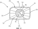
Фиг.2 представляет собой вид сверху режущей пластины, изображенной на фиг.1;Figure 2 is a top view of the cutting insert shown in figure 1;
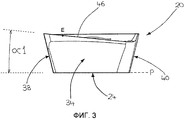
Фиг.3 представляет собой вид сбоку первой боковой поверхности режущей пластины, изображенной на фиг.1;Figure 3 is a side view of the first side surface of the cutting insert shown in figure 1;
Фиг.4 представляет собой вид сбоку второй боковой поверхности режущей пластины, изображенной на фиг.1;Figure 4 is a side view of the second side surface of the cutting insert shown in figure 1;
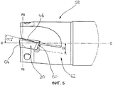
Фиг.5 представляет собой вид сбоку фрезы с режущей пластиной в соответствии с первым вариантом осуществления в первом поворотном положении индексации;5 is a side view of a milling cutter with a cutting insert in accordance with the first embodiment in the first indexing pivot position;
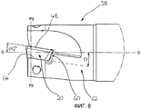
Фиг.6 представляет собой вид сбоку фрезы с режущей пластиной в соответствии с первым вариантом осуществления во втором поворотном положении;6 is a side view of a milling cutter with a cutting insert in accordance with the first embodiment in the second rotary position;
Фиг.7 представляет собой вид в перспективе режущей пластины в соответствии со вторым вариантом осуществления настоящего изобретения;7 is a perspective view of a cutting insert in accordance with a second embodiment of the present invention;
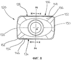
Фиг.8 представляет собой вид сверху режущей пластины, изображенной на фиг.7;Fig.8 is a top view of the cutting insert shown in Fig.7;
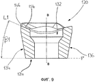
Фиг.9 представляет собой вид в разрезе режущей пластины, показанной на фиг.8, выполненный по линии IX-IX;Fig.9 is a view in section of the cutting insert shown in Fig.8, made along the line IX-IX;
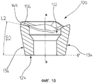
Фиг.10 представляет собой вид в разрезе режущей пластины, показанной на фиг.8, выполненный по линии Х-Х;Figure 10 is a sectional view of the cutting insert shown in Fig. 8, taken along the line XX;
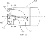
Фиг.11 представляет собой вид сбоку фрезы с режущей пластиной в соответствии со вторым вариантом осуществления в первом поворотном положении;11 is a side view of a milling cutter with a cutting insert in accordance with a second embodiment in a first pivot position;
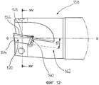
Фиг.12 представляет собой вид сбоку фрезы с режущей пластиной в соответствии со вторым вариантом осуществления, во втором поворотном положении;12 is a side view of a milling cutter with a cutting insert according to a second embodiment, in a second pivoting position;
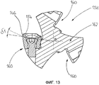
Фиг.13 представляет собой вид в разрезе режущей пластины, показанной на фиг.11, выполненный по линии XIII-XIII; иFig.13 is a view in section of the cutting insert shown in Fig.11, made along the line XIII-XIII; and
Фиг.14 представляет собой вид в разрезе режущей пластины, показанной на фиг.12, выполненный по линии XIV-XIV.Fig. 14 is a sectional view of the insert shown in Fig. 12 taken along line XIV-XIV.
Подробное описание изобретенияDETAILED DESCRIPTION OF THE INVENTION
На фиг.1 изображена многогранная режущая пластина 20, которая может быть изготовлена прессованием и спеканием цементированного карбида, такого как карбид вольфрама, и может иметь или не иметь покрытие.Figure 1 shows a
Режущая пластина 20 имеет верхнюю поверхность 22 и противоположную нижнюю поверхность 24, которая образует нижнюю плоскость Р, при этом периферийная боковая поверхность 26 продолжается между ними. Верхний и нижний периферийные края 28 и 30 образованы на пересечении периферийной боковой поверхности 26 с верхней поверхностью 22 и нижней поверхностью 24 соответственно. Фиксирующее сквозное отверстие 32 продолжается между верхней поверхностью 22 и нижней поверхностью 24 и открывается наружу к верхней поверхности 22 и нижней поверхности 24. Режущая пластина 20 может поворачиваться вокруг оси А пластины, коаксиальной фиксирующему сквозному отверстию 32.The cutting
Периферийная боковая поверхность 26 имеет противоположные первую и вторую боковые поверхности 34 и 36 и противоположные первую и вторую торцевые поверхности 38 и 40. Каждая из противоположных первой и второй боковых поверхностей 34 и 36 может включать в себя идентичные боковые прилегающие поверхности 42, которые являются по существу плоскими. Каждая из противоположных первой и второй торцевых поверхностей 38 и 40 может включать в себя идентичные торцевые прилегающие поверхности 44, которые являются по существу плоскими.The peripheral side surface 26 has opposite first and second side surfaces 34 and 36 and opposite first and second end surfaces 38 and 40. Each of the opposite first and second side surfaces 34 and 36 may include identical side adjacent surfaces 42, which are essentially flat. Each of the opposing first and second end surfaces 38 and 40 may include identical end abutting surfaces 44, which are substantially flat.
Верхний периферийный край 28 имеет первую главную режущую кромку 46, смежную первой боковой поверхностью 34, и вторую главную режущую кромку 48, смежную второй боковой поверхностью 36. Верхний периферийный край 28 может иметь две идентичные вспомогательные режущие кромки 50, смежные каждой из противоположных первой и второй торцевых поверхностей 38 и 40, и две идентичные угловые режущие кромки 52, соединяющие каждую из первой и второй главных режущих кромок 46 и 48, с соответствующей вспомогательной режущей кромкой 50. Верхняя поверхность 22 имеет первую и вторую передние поверхности 54 и 56, смежные каждой из первой и второй главных режущих кромок 46 и 48 соответственно.The upper
Согласно первому варианту осуществления настоящего изобретения, как показано на фиг.2, 3 и 4, первый осевой передний угол α1 пластины расположен между линией, касательной к первой главной режущей кромке 46 в первой передней точке Е, и нижней плоскостью Р, а второй осевой передний угол α2 пластины расположен между линией, касательной ко второй главной режущей кромке 48 во второй передней точке F, и нижней плоскостью Р, причем первый осевой передний угол α1 больше, чем второй осевой передний угол α2. Первая передняя точка Е находится на первой поворотной плоскости Р1, которая содержит ось А пластины, а вторая передняя точка F находится на второй поворотной плоскости Р2, которая также содержит ось А пластины и имеет поворотный угол ψ с первой поворотной плоскостью Р1. Поворотный угол ψ равен 360°/n, где n - количество главных режущих кромок 46, 48, для этого варианта осуществления n=2, означающее, что ψ=180°, так, что первая передняя точка Е и вторая передняя точка F занимают одно и то же положение относительно оси А пластины, при повороте на 180°. Первый и второй осевые передние углы α1 и α2 пластины могут быть по существу постоянными вдоль длины первой и второй главных режущих кромок 46 и 48 соответственно.According to a first embodiment of the present invention, as shown in FIGS. 2, 3 and 4, the first axial rake angle α1 of the insert is located between the line tangent to the first
Вышеприведенное определение «осевого переднего угла пластины» позволяет главным режущим кромкам многогранной режущей пластины быть сравниваемыми в эквивалентных передних точках, когда режущая пластина находится «в работе».The above definition of “axial rake angle” allows the main cutting edges of the polyhedral cutting insert to be compared at equivalent leading points when the cutting insert is “in operation”.
Следующие ссылки на «осевой передний угол фрезы» относятся к «истинному» осевому переднему углу, измеренному между линией, касательной к главной режущей кромке в передней точке, и продольной осью фрезы.The following references to the “axial rake angle of the cutter” refer to the “true” axial rake angle measured between the line tangent to the main cutting edge at the leading point and the longitudinal axis of the cutter.
Далее, на фиг.5 и 6 показана фреза 58 с режущей пластиной 20 в первом и втором поворотном положении соответственно, съемно установленной в заданном гнезде 60 для установки пластины корпуса 62 фрезы. Корпус 62 фрезы имеет три идентичных гнезда 60 для установки пластины, при этом каждое гнездо 60 для установки пластины имеет по существу плоскую установочную поверхность 64 гнезда, наклоненную под тем же углом θ гнезда относительно центральной продольной оси С. На фиг.5 первая главная режущая кромка 46 находится в рабочем положении и имеет первый осевой передний угол α1' фрезы, а на фиг.6 вторая главная режущая кромка 48 находится в рабочем положении и имеет второй осевой передний угол α2' фрезы, причем первый осевой передний угол α1' фрезы больше, чем второй осевой передний угол α2' фрезы. Первый и второй осевые передние углы α1' и α2' фрезы измеряются в передних точках на первой и второй главных режущих кромках 46 и 48 соответственно, занимающих одну и ту же радиальную плоскость Р3, перпендикулярную продольной оси С корпуса 62 фрезы, и могут быть по существу постоянными вдоль длины первой и второй главных режущих кромок 46 и 48.Next, FIGS. 5 and 6 show a
Фреза 58 может иметь, например, корпус 62 фрезы с тремя идентичными гнездами 60 для установки пластины, при этом три идентичных режущих пластины 20 могут удерживаться в одном из двух поворотных положений для обеспечения следующих возможных конфигураций режущего инструмента: (i) три режущие пластины 20 имеют первую главную режущую кромку 46 с рабочим первым осевым передним углом α1'; (ii) три режущие пластины 20 имеют вторую главную режущую кромку 48 с рабочим вторым осевым передним углом α2'; (iii) две режущие пластины 20 имеют первую главную режущую кромку 46 с рабочим первым осевым передним углом α1', а одна режущая пластина 20 имеет вторую главную режущую кромку 48 с рабочим вторым осевым передним углом α2'; и (iv) одна режущая пластина 20 имеет первую главную режущую кромку 46 с рабочим первым осевым передним углом α1', а две режущие пластины 20 имеют вторую главную режущую кромку 48 с рабочим вторым осевым передним углом α2'. Таким образом, наиболее подходящая конфигурация режущего инструмента в отношении различных комбинаций осевых передних углов может быть выбрана с использованием единственной группы идентичных режущих пластин 20. В частности, конфигурации (iii) и (iv) могут быть использованы для уменьшения/устранения вибрации при обеспечении оптимизированных рабочих параметров.Milling
На фиг.7 и 8 показана многогранная режущая пластина 120 с верхней поверхностью 122 и противоположной нижней поверхностью 124, которая образует нижнюю плоскость Р', и периферийной боковой поверхностью 126, продолжающейся между ними. Верхний и нижний периферийные края 128 и 130 образованы на пересечении периферийной боковой поверхности 126 с верхней поверхностью 122 и нижней поверхностью 124 соответственно. Фиксирующее сквозное отверстие 132 продолжается между верхней поверхностью 122 и нижней поверхностью 124 и открывается наружу к верхней поверхности 122 и нижней поверхности 124. Режущая пластина 120 может поворачиваться вокруг оси В пластины, коаксиальной фиксирующему сквозному отверстию 132.Figures 7 and 8 show a
Периферийная боковая поверхность 126 имеет противоположные первую и вторую боковые поверхности 134 и 136 и противоположные первую и вторую торцевые поверхности 138 и 140. Каждая из противоположных первой и второй боковых поверхностей 134 и 136 может включать в себя идентичные боковые прилегающие поверхности 142, которые являются по существу плоскими. Каждая из противоположных первой и второй торцевых поверхностей 138 и 140 может включать в себя идентичные торцевые прилегающие поверхности 144, которые являются по существу плоскими.The
Верхний периферийный край 128 имеет первую главную режущую кромку 146, смежную первой боковой поверхности 134, и вторую главную режущую кромку 148, смежную второй боковой поверхности 136. Верхний периферийный край 128 может иметь две идентичные вспомогательные режущие кромки 150, смежные каждой из противоположных первой и второй торцевых поверхностей 138 и 140, и две идентичные угловые режущие кромки 152, соединяющие каждую из первой и второй главных режущих кромок 146 и 148, с соответствующей вспомогательной режущей кромкой 150. Верхняя поверхность 122 содержит первую и вторую передние поверхности 154 и 156, смежные каждой из первой и второй главных режущих кромок 146 и 148 соответственно.The upper
Согласно второму варианту осуществления настоящего изобретения, как показано на фиг.9 и 10, первый угол β1 профиля передней поверхности расположен между первой линией L1, коллинеарной профилю сечения первой передней поверхности 154 по меньшей мере вблизи первой главной режущей кромки 146, и нижней плоскостью Р', а второй угол β2 профиля передней поверхности расположен между второй линией L2, коллинеарной профилю сечения второй передней поверхности 156 по меньшей мере вблизи первой главной режущей кромки 148, и нижней плоскостью Р'. Первая и вторая линии L1 и L2 лежат в первой и второй центральных плоскостях Р4 и Р5, которые содержат ось В пластины и перпендикулярны первой и второй главным режущим кромкам 146 и 148 соответственно.According to a second embodiment of the present invention, as shown in FIGS. 9 and 10, a first front surface profile angle β1 is located between the first line L1, the collinear sectional profile of the first
Вышеприведенное определение «угла профиля передней поверхности» позволяет передним поверхностям многогранной режущей пластины быть сравниваемыми в эквивалентных сечениях, когда режущая пластина находится «в работе». Следует понимать, что определение «угла профиля передней поверхности» также может применяться к передним поверхностям, непосредственно смежным режущим кромкам, называемым «фасками».The above definition of “front surface profile angle” allows the front surfaces of the polyhedral cutting insert to be compared in equivalent sections when the cutting insert is “in operation”. It should be understood that the definition of the "angle of the profile of the front surface" can also be applied to the front surfaces directly adjacent to the cutting edges, called "chamfers".
Следующие ссылки на «радиальный передний угол фрезы» относятся к «истинному» радиальному переднему углу, как измеренному в сечении, проходящем через произвольную точку вдоль главной режущей кромки, как угол между ее соответствующей передней поверхностью и радиусом относительно оси фрезы.The following references to the "radial rake angle of the cutter" refer to the "true" radial rake angle, as measured in cross section passing through an arbitrary point along the main cutting edge, as the angle between its corresponding front surface and the radius relative to the axis of the cutter.
На фиг.11, 13 и 12, 14 показана фреза 158 с режущей пластиной 120 в первом и втором поворотных положениях соответственно, съемно установленной в заданном гнезде 160 для установки пластины корпуса 162 фрезы. Корпус 162 фрезы имеет три идентичных гнезда 160 для установки пластины, при этом каждое гнездо 160 для установки пластины имеет по существу плоскую установочную поверхность 164 гнезда, наклоненную под тем же углом θ' гнезда относительно центральной продольной оси D. На фиг.13 первая передняя поверхность 154 находится в рабочем положении и имеет первый радиальный передний угол δ1, который является по существу постоянным вдоль первой главной режущей кромки 146, а на фиг.14 вторая передняя поверхность 156 находится в рабочем положении и имеет второй радиальный передний угол δ2, который является по существу постоянным вдоль второй главной режущей кромки 148, причем первый радиальный передний угол δ1 больше, чем второй радиальный передний угол δ2.11, 13 and 12, 14 show a
Фреза 158 может иметь, например, корпус 162 фрезы с тремя идентичными гнездами 160 для установки пластины, при этом три идентичных режущих пластины 120 могут удерживаться в одном из двух поворотных положений для обеспечения следующих возможных конфигураций режущего инструмента: (i) три режущие пластины 120 имеют первую переднюю поверхность 154 с рабочим первым радиальным передним углом δ1; (ii) три режущие пластины 20 имеют вторую переднюю поверхность 156 с рабочим вторым радиальным передним углом δ2; (iii) две режущие пластины 20 имеют первую переднюю поверхность 154 с рабочим первым радиальным передним углом δ1, а одна режущая пластина 20 имеет вторую переднюю поверхность 156 с рабочим вторым радиальным передним углом δ2; и (iv) одна режущая пластина 20 имеет первую переднюю поверхность 154 с рабочим первым радиальным передним углом δ1, а две режущие пластины 20 имеют вторую переднюю поверхность 156 с рабочим вторым радиальным передним углом δ2. Таким образом, наиболее подходящая конфигурация режущего инструмента в отношении различных комбинаций радиальных передних углов может быть выбрана с использованием единственной группы идентичных режущих пластин 120. В частности, конфигурации (iii) и (iv) могут быть использованы для уменьшения/устранения вибрации при обеспечении оптимизированных рабочих параметров.The
Хотя настоящее изобретение было описано с некоторой степенью конкретности, следует понимать, что могут быть выполнены различные изменения и дополнения, не выходящие за рамки сущности и объема настоящего изобретения, как заявлено в нижеприведенной формуле изобретения.Although the present invention has been described with some degree of specificity, it should be understood that various changes and additions can be made without departing from the essence and scope of the present invention, as claimed in the following claims.
Claims (14)
верхнюю поверхность (22, 122) и противоположную нижнюю поверхность (24, 124) с периферийной боковой поверхностью (26, 126), продолжающейся между
ними,
фиксирующее сквозное отверстие (32, 132), продолжающееся между верхней поверхностью (22, 122) и нижней поверхностью (24, 124) и открывающееся наружу к верхней поверхности (22, 122) и нижней поверхности (24, 124), при этом фиксирующее сквозное отверстие (32, 132) имеет ось А, В пластины, вокруг которой режущая пластина (20, 120) имеет возможность поворота, по меньшей мере две главные режущие кромки (46, 146; 48, 148), образованные на верхнем периферийном крае (28, 128) на пересечении верхней поверхности (22, 122) и периферийной боковой поверхности (26, 126), и
имеющая по меньшей мере две поворотных плоскости P1, Р2, содержащие ось А, В пластины и по меньшей мере две главные режущие кромки (46, 146; 48, 148),
по меньшей мере две передние точки Е, F, в которых по меньшей мере две поворотных плоскости P1, Р2 пересекают по меньшей мере две главные режущие кромки (46, 146; 48, 148), и
по меньшей мере два осевых передних угла α1, α2 пластины между линиями, касательными к по меньшей мере двум главным режущим кромкам (46, 146; 48, 148) в по меньшей мере двух передних точках Е, F, и нижней плоскостью Р, Р', образованной нижней поверхностью (24, 124),
при этом поворотный угол ψ, равный 360°/n, расположен между по меньшей мере двумя поворотными плоскостями P1, Р2, где n - количество главных режущих кромок (46, 146; 48, 148),
причем по меньшей мере два из по меньшей мере двух осевых передних углов α1, α2 пластины отличаются друг от друга.1. A multifaceted cutting insert (20, 120) containing
the upper surface (22, 122) and the opposite lower surface (24, 124) with a peripheral side surface (26, 126) extending between
them
a fixing through hole (32, 132) extending between the upper surface (22, 122) and the lower surface (24, 124) and opening outward to the upper surface (22, 122) and the lower surface (24, 124), while fixing the through the hole (32, 132) has an axis A, B of the insert, around which the cutting insert (20, 120) has the ability to rotate at least two main cutting edges (46, 146; 48, 148) formed on the upper peripheral edge (28 , 128) at the intersection of the upper surface (22, 122) and the peripheral lateral surface (26, 126), and
having at least two rotary planes P1, P2, containing the axis A, B of the insert and at least two main cutting edges (46, 146; 48, 148),
at least two leading points E, F, in which at least two pivoting planes P1, P2 intersect at least two main cutting edges (46, 146; 48, 148), and
at least two axial rake angles α1, α2 of the insert between lines tangent to at least two major cutting edges (46, 146; 48, 148) at least two leading points E, F, and the lower plane P, P ' formed by the lower surface (24, 124),
wherein the rotational angle ψ equal to 360 ° / n is located between at least two rotary planes P1, P2, where n is the number of main cutting edges (46, 146; 48, 148),
moreover, at least two of at least two axial rake angles α1, α2 of the plate are different from each other.
верхнюю поверхность (22, 122) и противоположную нижнюю поверхность (24, 124) с периферийной боковой поверхностью (26, 126), продолжающейся между ними,
фиксирующее сквозное отверстие (32, 132), продолжающееся между верхней поверхностью (22, 122) и нижней поверхностью (24, 124) и открывающееся наружу к верхней поверхности (22, 122) и нижней поверхности (24, 124), при этом фиксирующее сквозное отверстие (32, 132) имеет ось А, В пластины, вокруг которой режущая пластина (20, 120) имеет возможность поворота,
по меньшей мере две главные режущие кромки (46, 146; 48, 148), образованные на верхнем периферийном крае (28, 128) на пересечении верхней поверхности (22, 122) и периферийной боковой поверхности (26, 126),
по меньшей мере две передние поверхности (54, 154; 56, 156), образованные на верхней поверхности (22, 122) смежно каждой из по меньшей мере двух главных режущих кромок (46, 146; 48, 148),
и по меньшей мере две центральные плоскости Р4, Р5, содержащие ось А, В пластины и перпендикулярные по меньшей мере двум главным режущим кромкам (46, 146; 48, 148), и
по меньшей мере два угла β1, β2 профиля передней поверхности между линиями L1, L2, коллинеарными вблизи по меньшей мере двух главных режущих кромок (46, 146; 48, 148) профилям сечения по меньшей мере двух передних поверхностей (54, 154; 56, 156), выполненным в по меньшей мере двух центральных плоскостях Р4, Р5, и нижней плоскостью Р, Р', образованной нижней поверхностью (24, 124),
при этом по меньшей мере два из по меньшей мере двух углов β1, β2 профиля передней поверхности отличаются друг от друга.8. A multifaceted cutting insert (20, 120) containing
the upper surface (22, 122) and the opposite lower surface (24, 124) with a peripheral side surface (26, 126) extending between them,
a fixing through hole (32, 132) extending between the upper surface (22, 122) and the lower surface (24, 124) and opening outward to the upper surface (22, 122) and the lower surface (24, 124), while fixing the through the hole (32, 132) has an axis A, B of the insert, around which the cutting insert (20, 120) is rotatable,
at least two main cutting edges (46, 146; 48, 148) formed at the upper peripheral edge (28, 128) at the intersection of the upper surface (22, 122) and the peripheral side surface (26, 126),
at least two front surfaces (54, 154; 56, 156) formed on the upper surface (22, 122) adjacent to each of the at least two main cutting edges (46, 146; 48, 148),
and at least two central planes P4, P5, containing the axis A, B of the insert and perpendicular to at least two main cutting edges (46, 146; 48, 148), and
at least two angles β1, β2 of the profile of the front surface between the lines L1, L2, collinear near at least two main cutting edges (46, 146; 48, 148) of the section profiles of at least two front surfaces (54, 154; 56, 156), made in at least two central planes P4, P5, and a lower plane P, P 'formed by the lower surface (24, 124),
wherein at least two of the at least two angles β1, β2 of the front surface profile are different from each other.
по меньшей мере две передние точки Е, F, в которых по меньшей мере две поворотных плоскости P1, Р2 пересекают по меньшей мере две главные режущие кромки (46, 146; 48, 148), и
по меньшей мере два осевых передних угла α1, α2 пластины между линиями, касательными к по меньшей мере двум главным режущим кромкам (46, 146; 48, 148) в по меньшей мере двух передних точках Е, F, и нижней плоскостью Р, Р', при этом поворотный угол ψ, равный 360°/n, расположен между по меньшей мере двумя поворотными плоскостями P1, Р2, где n - количество главных режущих кромок (46, 146; 48, 148), и причем по меньшей мере два из по меньшей мере двух осевых передних углов α1, α2 пластины отличаются друг от друга.9. The insert (20, 120) according to claim 8, having at least two rotary planes P1, P2, containing the axis A, B of the insert and at least two main cutting edges (46, 146; 48, 148),
at least two leading points E, F, in which at least two pivoting planes P1, P2 intersect at least two main cutting edges (46, 146; 48, 148), and
at least two axial rake angles α1, α2 of the insert between lines tangent to at least two major cutting edges (46, 146; 48, 148) at least two leading points E, F, and the lower plane P, P ' wherein the rotational angle ψ equal to 360 ° / n is located between at least two rotary planes P1, P2, where n is the number of main cutting edges (46, 146; 48, 148), and wherein at least two of at least two axial rake angles α1, α2 of the plate are different from each other.
корпус (62, 162) фрезы с множеством гнезд (60, 160) для установки пластины и равным количеством идентичных многогранных режущих пластин (20, 120), при этом каждое гнездо (60, 160) для установки пластины имеет, по существу, плоскую установочную поверхность (64, 164) гнезда, наклоненную под тем же углом θ, θ' гнезда относительно центральной продольной оси C, D, причем каждая идентичная многогранная режущая пластина (20, 120), съемно установленная в одном из множества гнезд (60, 160) для установки пластины, имеет
по меньшей мере две главные режущие кромки (46, 146; 48, 148), включающие в себя рабочие главные режущие кромки (46, 146; 48, 148), и две соответствующие передние поверхности (54, 154; 56, 156), включающие в себя рабочие передние поверхности (54, 154; 56, 156),
при этом в радиальной плоскости Р3, перпендикулярной центральной продольной оси C, D, по меньшей мере две из идентичных режущих пластин (20, 120) имеют по меньшей мере одно из осевых передних углов α1', α2' фрезы разной величины, и радиальных передних углов δ1, δ2 фрезы разной величины.11. A mill (58, 158) containing
a cutter body (62, 162) with a plurality of sockets (60, 160) for inserting the insert and an equal number of identical polyhedral cutting inserts (20, 120), each nest (60, 160) for inserting the insert has a substantially flat mounting the surface (64, 164) of the nest, inclined at the same angle θ, θ 'of the nest relative to the central longitudinal axis C, D, each identical polyhedral cutting insert (20, 120), removably mounted in one of the many nests (60, 160) to install the plate, has
at least two main cutting edges (46, 146; 48, 148), including working main cutting edges (46, 146; 48, 148), and two corresponding front surfaces (54, 154; 56, 156), including working front surfaces (54, 154; 56, 156),
in the radial plane P3 perpendicular to the central longitudinal axis C, D, at least two of the identical cutting inserts (20, 120) have at least one of the axial rake angles α1 ', α2' of the milling cutter of different sizes, and radial rake angles δ1, δ2 milling cutters of different sizes.
Applications Claiming Priority (3)
| Application Number | Priority Date | Filing Date | Title |
|---|---|---|---|
| IL193284 | 2008-08-06 | ||
| IL193284A IL193284A (en) | 2008-08-06 | 2008-08-06 | Milling cutter and cutting insert therefor |
| PCT/IL2009/000638 WO2010016052A1 (en) | 2008-08-06 | 2009-06-28 | Milling cutter and cutting insert therefor |
Publications (2)
| Publication Number | Publication Date |
|---|---|
| RU2011108547A RU2011108547A (en) | 2012-09-20 |
| RU2483844C2 true RU2483844C2 (en) | 2013-06-10 |
Family
ID=41165499
Family Applications (1)
| Application Number | Title | Priority Date | Filing Date |
|---|---|---|---|
| RU2011108547/02A RU2483844C2 (en) | 2008-08-06 | 2009-06-28 | Cutter and its cutting tool |
Country Status (14)
| Country | Link |
|---|---|
| US (1) | US8172487B2 (en) |
| EP (1) | EP2313224B1 (en) |
| JP (1) | JP5491505B2 (en) |
| KR (1) | KR101569551B1 (en) |
| CN (2) | CN103028770B (en) |
| BR (1) | BRPI0915569B1 (en) |
| CA (1) | CA2731348C (en) |
| ES (1) | ES2663534T3 (en) |
| IL (1) | IL193284A (en) |
| PL (1) | PL2313224T3 (en) |
| PT (1) | PT2313224T (en) |
| RU (1) | RU2483844C2 (en) |
| TW (1) | TW201008681A (en) |
| WO (1) | WO2010016052A1 (en) |
Cited By (2)
| Publication number | Priority date | Publication date | Assignee | Title |
|---|---|---|---|---|
| RU2562195C1 (en) * | 2014-03-04 | 2015-09-10 | Общество с ограниченной ответственнстью "Сборные конструкции инструмента, фрезы Москвитина" | Cutter (versions) |
| RU2583975C1 (en) * | 2014-12-23 | 2016-05-10 | Общество с ограниченной ответственностью "Сборные конструкции инструмента, фрезы Москвитина" | Disc mill (versions) and cutting plate therefor |
Families Citing this family (21)
| Publication number | Priority date | Publication date | Assignee | Title |
|---|---|---|---|---|
| SE534715C2 (en) * | 2010-03-23 | 2011-11-29 | Sandvik Intellectual Property | Cutters and cutters for this |
| JP2012152868A (en) * | 2011-01-27 | 2012-08-16 | Mitsubishi Materials Corp | Cutting insert and cutting edge change type cutting tool |
| DE102011117148B4 (en) * | 2011-10-28 | 2022-05-05 | Kennametal Inc. | Rotary tool and method for producing a rotary tool and a cutting insert |
| WO2013065393A1 (en) * | 2011-10-31 | 2013-05-10 | 京セラ株式会社 | Cutting insert, cutting tool, and method for manufacturing cut product using cutting tool |
| JP2013215858A (en) * | 2012-04-11 | 2013-10-24 | Dijet Industrial Co Ltd | Radius end mill |
| RU2492974C1 (en) * | 2012-06-20 | 2013-09-20 | Нина Алексеевна Корюкина | Composite end mill |
| RU2494841C1 (en) * | 2012-07-25 | 2013-10-10 | Нина Алексеевна Корюкина | Composite end mill |
| USD738412S1 (en) * | 2013-12-25 | 2015-09-08 | Taegutec Ltd. | Cutting insert |
| USD752664S1 (en) * | 2014-09-25 | 2016-03-29 | Taegutec Ltd. | Cutting insert |
| US9981323B2 (en) | 2015-07-16 | 2018-05-29 | Kennametal Inc. | Double-sided tangential cutting insert and cutting tool system using the same |
| USD777230S1 (en) | 2015-07-16 | 2017-01-24 | Kennametal Inc | Double-sided tangential cutting insert |
| USD778330S1 (en) | 2015-07-16 | 2017-02-07 | Kennametal Inc. | Double-sided tangential cutting insert |
| JP6817717B2 (en) | 2016-04-07 | 2021-01-20 | 三菱マテリアル株式会社 | Milling cutters, cutting inserts and milling methods |
| KR101941973B1 (en) * | 2017-04-11 | 2019-01-24 | 한국야금 주식회사 | High feed cutting insert and cutting tool for mounting the same |
| CN107350530B (en) * | 2017-08-31 | 2024-01-23 | 炎陵欧科亿数控精密刀具有限公司 | Indexable insert for large feed milling |
| JP6508620B1 (en) * | 2017-10-25 | 2019-05-08 | 株式会社タンガロイ | Cutting insert and cutting edge exchange type cutting tool |
| CN107876847A (en) * | 2017-11-20 | 2018-04-06 | 中山市园丰精密刃具有限公司 | A kind of double end cutter block |
| CN107812993A (en) * | 2017-11-21 | 2018-03-20 | 中山市园丰精密刃具有限公司 | A kind of mobile phone volume key milling cutter |
| TWI768131B (en) * | 2017-11-30 | 2022-06-21 | 以色列商艾斯卡公司 | Single-sided four-way indexable positive cutting insert and insert mill therefor |
| CN113573834A (en) * | 2019-03-27 | 2021-10-29 | 住友电工硬质合金株式会社 | Cutting insert |
| CN114769689B (en) * | 2022-05-30 | 2023-12-29 | 山东理工大学 | Progressive oblique line cutting edge micro drilling and milling cutter |
Citations (4)
| Publication number | Priority date | Publication date | Assignee | Title |
|---|---|---|---|---|
| SU1423291A1 (en) * | 1986-04-09 | 1988-09-15 | Сестрорецкий Инструментальный Завод Им.Воскова | Cutting bit |
| RU2106936C1 (en) * | 1992-05-25 | 1998-03-20 | Искар Лтд. | Cutter insert |
| US6619891B2 (en) * | 2000-04-28 | 2003-09-16 | Sandvik Aktiebolag | Milling tool having cutting members with different clearance angles |
| RU2284249C1 (en) * | 2005-05-23 | 2006-09-27 | Нина Алексеевна Корюкина | Tangential cutting tip |
Family Cites Families (22)
| Publication number | Priority date | Publication date | Assignee | Title |
|---|---|---|---|---|
| US4808044A (en) | 1986-04-30 | 1989-02-28 | Mitsubishi Kinzoku Kabushiki Kaisha | Insert cutter |
| IL93883A (en) | 1989-04-12 | 1993-02-21 | Iscar Ltd | Cutting insert for a milling cutting tool |
| JP2833283B2 (en) * | 1991-09-05 | 1998-12-09 | 三菱マテリアル株式会社 | Indexable tip |
| DE9320349U1 (en) * | 1992-05-25 | 1994-08-04 | Iscar Ltd | Interchangeable cutter inserts |
| US5388932A (en) * | 1993-09-13 | 1995-02-14 | Kennametal Inc. | Cutting insert for a milling cutter |
| WO1996018472A1 (en) * | 1994-12-10 | 1996-06-20 | Kennametal Hertel Ag Werkzeuge + Hartstoffe | Drilling tool for drilling in solid metal |
| US5810519A (en) * | 1995-03-17 | 1998-09-22 | Kennametal Inc. | Helical cutting insert with offset cutting edges |
| US5853267A (en) * | 1996-08-22 | 1998-12-29 | Iscar Ltd. | Cutting insert |
| SE514014C2 (en) * | 1998-05-06 | 2000-12-11 | Sandvik Ab | Indexable cutting insert for rotary end mills |
| SE512040C2 (en) * | 1998-05-06 | 2000-01-17 | Sandvik Ab | Inserts for stick cutters |
| SE514032C2 (en) * | 1998-09-08 | 2000-12-11 | Seco Tools Ab | Tools and cutters for milling |
| IL141089A (en) * | 2001-01-25 | 2006-08-20 | Amir Satran | Cutting insert |
| IL150015A (en) * | 2002-06-04 | 2007-06-17 | Amir Satran | Cutting insert and milling cutter |
| JP4313579B2 (en) | 2003-01-22 | 2009-08-12 | オーエスジー株式会社 | Square end mill |
| IL155288A (en) * | 2003-04-08 | 2007-09-20 | Amir Satran | Tangential cutting insert and milling cutter |
| US7771142B2 (en) * | 2003-05-09 | 2010-08-10 | Kennametal Inc. | Cutting insert with elliptical cutting edge |
| US7399146B2 (en) * | 2003-09-29 | 2008-07-15 | Kennametal Inc. | Rotary cutting tool having irregular insert orientation |
| CN2649237Y (en) * | 2003-11-04 | 2004-10-20 | 哈尔滨理工大学 | Quasi-three-dimensional enclosed slot arc sleeking corner and chamfered corner transposable milling-cutter piece |
| US7070363B2 (en) * | 2004-07-15 | 2006-07-04 | Kennametal Inc. | Cutting insert for high-speed milling cutter |
| US7104735B2 (en) * | 2004-09-02 | 2006-09-12 | Ingersoll Cutting Tool Company | Tangential cutting insert and milling cutter |
| US7452167B2 (en) * | 2004-11-26 | 2008-11-18 | Kyocera Corporation | Cutting insert and milling tool |
| JP4971649B2 (en) | 2006-02-28 | 2012-07-11 | 京セラ株式会社 | Cutting tools |
-
2008
- 2008-08-06 IL IL193284A patent/IL193284A/en active IP Right Grant
- 2008-08-27 TW TW097132768A patent/TW201008681A/en unknown
-
2009
- 2009-06-19 US US12/488,326 patent/US8172487B2/en active Active
- 2009-06-28 JP JP2011521682A patent/JP5491505B2/en active Active
- 2009-06-28 PT PT97874465T patent/PT2313224T/en unknown
- 2009-06-28 RU RU2011108547/02A patent/RU2483844C2/en active
- 2009-06-28 EP EP09787446.5A patent/EP2313224B1/en active Active
- 2009-06-28 CN CN201210582143.9A patent/CN103028770B/en active Active
- 2009-06-28 CN CN200980129725.8A patent/CN102112259B/en active Active
- 2009-06-28 KR KR1020117002651A patent/KR101569551B1/en active IP Right Grant
- 2009-06-28 CA CA2731348A patent/CA2731348C/en active Active
- 2009-06-28 PL PL09787446T patent/PL2313224T3/en unknown
- 2009-06-28 ES ES09787446.5T patent/ES2663534T3/en active Active
- 2009-06-28 WO PCT/IL2009/000638 patent/WO2010016052A1/en active Application Filing
- 2009-06-28 BR BRPI0915569A patent/BRPI0915569B1/en active IP Right Grant
Patent Citations (4)
| Publication number | Priority date | Publication date | Assignee | Title |
|---|---|---|---|---|
| SU1423291A1 (en) * | 1986-04-09 | 1988-09-15 | Сестрорецкий Инструментальный Завод Им.Воскова | Cutting bit |
| RU2106936C1 (en) * | 1992-05-25 | 1998-03-20 | Искар Лтд. | Cutter insert |
| US6619891B2 (en) * | 2000-04-28 | 2003-09-16 | Sandvik Aktiebolag | Milling tool having cutting members with different clearance angles |
| RU2284249C1 (en) * | 2005-05-23 | 2006-09-27 | Нина Алексеевна Корюкина | Tangential cutting tip |
Cited By (2)
| Publication number | Priority date | Publication date | Assignee | Title |
|---|---|---|---|---|
| RU2562195C1 (en) * | 2014-03-04 | 2015-09-10 | Общество с ограниченной ответственнстью "Сборные конструкции инструмента, фрезы Москвитина" | Cutter (versions) |
| RU2583975C1 (en) * | 2014-12-23 | 2016-05-10 | Общество с ограниченной ответственностью "Сборные конструкции инструмента, фрезы Москвитина" | Disc mill (versions) and cutting plate therefor |
Also Published As
| Publication number | Publication date |
|---|---|
| CA2731348C (en) | 2016-08-09 |
| RU2011108547A (en) | 2012-09-20 |
| BRPI0915569A2 (en) | 2019-08-27 |
| EP2313224B1 (en) | 2018-01-24 |
| US8172487B2 (en) | 2012-05-08 |
| JP5491505B2 (en) | 2014-05-14 |
| KR101569551B1 (en) | 2015-11-16 |
| KR20110050633A (en) | 2011-05-16 |
| WO2010016052A1 (en) | 2010-02-11 |
| ES2663534T3 (en) | 2018-04-13 |
| EP2313224A1 (en) | 2011-04-27 |
| JP2011530415A (en) | 2011-12-22 |
| US20100034601A1 (en) | 2010-02-11 |
| PT2313224T (en) | 2018-02-19 |
| CN102112259A (en) | 2011-06-29 |
| PL2313224T3 (en) | 2018-05-30 |
| CN103028770A (en) | 2013-04-10 |
| IL193284A (en) | 2014-06-30 |
| BRPI0915569B1 (en) | 2020-12-22 |
| CN102112259B (en) | 2014-01-01 |
| CA2731348A1 (en) | 2010-02-11 |
| TW201008681A (en) | 2010-03-01 |
| CN103028770B (en) | 2015-06-17 |
Similar Documents
| Publication | Publication Date | Title |
|---|---|---|
| RU2483844C2 (en) | Cutter and its cutting tool | |
| RU2648717C2 (en) | Rotary cutting tool and reversible cutting insert thereof | |
| JP6532940B2 (en) | Double-sided cutting inserts and milling tools | |
| RU2519208C2 (en) | Insert and rotary cutting tool | |
| JP5690417B2 (en) | Cutting insert for right angle machining and milling cutter provided with the same | |
| US20200368830A1 (en) | Indexable rotary cutting tool and tool body | |
| JP4857958B2 (en) | Round piece insert removable cutting tool and round piece insert | |
| JP2015500150A (en) | Cutting inserts and cutting tools | |
| JP2011126008A (en) | Device for milling | |
| RU2721761C1 (en) | Tool housing for cylindrical face mill and cutting tool | |
| RU2698023C1 (en) | Vortex processing tool | |
| KR20170130573A (en) | Insert tool and thread mill | |
| JP2015523228A (en) | Cutting insert and cutting tool including the same | |
| JP2014083667A (en) | Cutting insert and tip replaceable cutting tool | |
| JP2007260788A (en) | Cutting insert and cutting tool | |
| US20210060668A1 (en) | Cutting insert | |
| JP4378307B2 (en) | Axial feed edge replaceable tool | |
| JP2015208835A (en) | Cutting edge replaceable face milling cutter and manufacturing method of the same | |
| KR20170130572A (en) | reamer | |
| JP5633395B2 (en) | Cutting insert and cutting edge changeable cutting tool | |
| CN117615871A (en) | Cutting insert and rotary cutting tool comprising same | |
| JP2008100316A (en) | Cutting tool, and finishing blade insert | |
| JP2010149234A (en) | Cutting insert, cutting tool, and cutting method using them | |
| JP6358306B2 (en) | Replaceable cutting head | |
| JP2007283467A (en) | Cutting insert and cutting tool |