RU2480806C2 - Gas turbine operation analysis method - Google Patents
Gas turbine operation analysis method Download PDFInfo
- Publication number
- RU2480806C2 RU2480806C2 RU2010121150/08A RU2010121150A RU2480806C2 RU 2480806 C2 RU2480806 C2 RU 2480806C2 RU 2010121150/08 A RU2010121150/08 A RU 2010121150/08A RU 2010121150 A RU2010121150 A RU 2010121150A RU 2480806 C2 RU2480806 C2 RU 2480806C2
- Authority
- RU
- Russia
- Prior art keywords
- gas turbine
- pressure signal
- parameters
- compressor
- measured
- Prior art date
Links
Images
Classifications
-
- G—PHYSICS
- G05—CONTROLLING; REGULATING
- G05B—CONTROL OR REGULATING SYSTEMS IN GENERAL; FUNCTIONAL ELEMENTS OF SUCH SYSTEMS; MONITORING OR TESTING ARRANGEMENTS FOR SUCH SYSTEMS OR ELEMENTS
- G05B23/00—Testing or monitoring of control systems or parts thereof
- G05B23/02—Electric testing or monitoring
- G05B23/0205—Electric testing or monitoring by means of a monitoring system capable of detecting and responding to faults
- G05B23/0218—Electric testing or monitoring by means of a monitoring system capable of detecting and responding to faults characterised by the fault detection method dealing with either existing or incipient faults
- G05B23/0224—Process history based detection method, e.g. whereby history implies the availability of large amounts of data
- G05B23/024—Quantitative history assessment, e.g. mathematical relationships between available data; Functions therefor; Principal component analysis [PCA]; Partial least square [PLS]; Statistical classifiers, e.g. Bayesian networks, linear regression or correlation analysis; Neural networks
-
- F—MECHANICAL ENGINEERING; LIGHTING; HEATING; WEAPONS; BLASTING
- F01—MACHINES OR ENGINES IN GENERAL; ENGINE PLANTS IN GENERAL; STEAM ENGINES
- F01D—NON-POSITIVE DISPLACEMENT MACHINES OR ENGINES, e.g. STEAM TURBINES
- F01D17/00—Regulating or controlling by varying flow
- F01D17/02—Arrangement of sensing elements
- F01D17/08—Arrangement of sensing elements responsive to condition of working-fluid, e.g. pressure
-
- F—MECHANICAL ENGINEERING; LIGHTING; HEATING; WEAPONS; BLASTING
- F02—COMBUSTION ENGINES; HOT-GAS OR COMBUSTION-PRODUCT ENGINE PLANTS
- F02C—GAS-TURBINE PLANTS; AIR INTAKES FOR JET-PROPULSION PLANTS; CONTROLLING FUEL SUPPLY IN AIR-BREATHING JET-PROPULSION PLANTS
- F02C9/00—Controlling gas-turbine plants; Controlling fuel supply in air- breathing jet-propulsion plants
-
- F—MECHANICAL ENGINEERING; LIGHTING; HEATING; WEAPONS; BLASTING
- F04—POSITIVE - DISPLACEMENT MACHINES FOR LIQUIDS; PUMPS FOR LIQUIDS OR ELASTIC FLUIDS
- F04D—NON-POSITIVE-DISPLACEMENT PUMPS
- F04D27/00—Control, e.g. regulation, of pumps, pumping installations or pumping systems specially adapted for elastic fluids
- F04D27/001—Testing thereof; Determination or simulation of flow characteristics; Stall or surge detection, e.g. condition monitoring
-
- F—MECHANICAL ENGINEERING; LIGHTING; HEATING; WEAPONS; BLASTING
- F05—INDEXING SCHEMES RELATING TO ENGINES OR PUMPS IN VARIOUS SUBCLASSES OF CLASSES F01-F04
- F05D—INDEXING SCHEME FOR ASPECTS RELATING TO NON-POSITIVE-DISPLACEMENT MACHINES OR ENGINES, GAS-TURBINES OR JET-PROPULSION PLANTS
- F05D2260/00—Function
- F05D2260/80—Diagnostics
-
- F—MECHANICAL ENGINEERING; LIGHTING; HEATING; WEAPONS; BLASTING
- F05—INDEXING SCHEMES RELATING TO ENGINES OR PUMPS IN VARIOUS SUBCLASSES OF CLASSES F01-F04
- F05D—INDEXING SCHEME FOR ASPECTS RELATING TO NON-POSITIVE-DISPLACEMENT MACHINES OR ENGINES, GAS-TURBINES OR JET-PROPULSION PLANTS
- F05D2270/00—Control
- F05D2270/70—Type of control algorithm
- F05D2270/707—Type of control algorithm fuzzy logic
-
- F—MECHANICAL ENGINEERING; LIGHTING; HEATING; WEAPONS; BLASTING
- F05—INDEXING SCHEMES RELATING TO ENGINES OR PUMPS IN VARIOUS SUBCLASSES OF CLASSES F01-F04
- F05D—INDEXING SCHEME FOR ASPECTS RELATING TO NON-POSITIVE-DISPLACEMENT MACHINES OR ENGINES, GAS-TURBINES OR JET-PROPULSION PLANTS
- F05D2270/00—Control
- F05D2270/70—Type of control algorithm
- F05D2270/709—Type of control algorithm with neural networks
Landscapes
- Engineering & Computer Science (AREA)
- Physics & Mathematics (AREA)
- Mechanical Engineering (AREA)
- General Engineering & Computer Science (AREA)
- Artificial Intelligence (AREA)
- Combustion & Propulsion (AREA)
- Chemical & Material Sciences (AREA)
- Evolutionary Computation (AREA)
- Mathematical Physics (AREA)
- General Physics & Mathematics (AREA)
- Automation & Control Theory (AREA)
- Control Of Positive-Displacement Air Blowers (AREA)
- Testing Of Engines (AREA)
Abstract
Description
Изобретение относится к способу анализа функционирования газовой турбины, а также к способу контроля функционирования газовой турбины.The invention relates to a method for analyzing the functioning of a gas turbine, as well as to a method for monitoring the functioning of a gas turbine.
Современные газовые турбины для применений генерации энергии и промышленных применений, а также для авиационных двигателей включают в себя чаще всего многоступенчатые осевые компрессоры, которые в процессе функционирования подвергаются действию разнообразных механизмов износа, загрязнения и других механизмов повреждения, которые отрицательно влияют на функционирование компрессора. Своевременное распознавание таких состояний машины, отклоняющихся от нормальных состояний, образует существенную предпосылку для введения мероприятий профилактического ремонта, чтобы избежать как критических рабочих состояний, так и недопустимого износа.Modern gas turbines for power generation and industrial applications, as well as for aircraft engines, most often include multistage axial compressors, which during operation are subject to a variety of wear, pollution and other damage mechanisms that adversely affect the functioning of the compressor. The timely recognition of such machine conditions that deviate from normal conditions forms an essential prerequisite for the introduction of preventive maintenance measures in order to avoid both critical operating conditions and unacceptable wear.
При диагностике и контроле современных газовых турбин особенно важны однозначная классификация и количественная оценка износа и повреждений. В частности, желательно, чтобы в газовых турбинах с многоступенчатыми осевыми компрессорами можно было точно указать, в какой компрессорной ступени возникает признак износа или повреждения и насколько сильным является или как далеко пошло повреждение по отношению к установленному предельному значению. Кроме того, такие способы диагностики и контроля должны проводиться в ходе нормальной эксплуатации и не требовать остановки турбины.In the diagnosis and control of modern gas turbines, a unique classification and quantitative assessment of wear and damage are especially important. In particular, it is desirable that in gas turbines with multi-stage axial compressors, it is possible to precisely indicate in which compressor stage a sign of wear or damage occurs and how severe or how far the damage has gone with respect to the set limit value. In addition, such diagnostic and control methods should be carried out during normal operation and not require the turbine to stop.
Из уровня техники известны различные способы диагностики и контроля для турбин. Например, в DE 4012278 А1 описана система диагностики состояния для установки паровой турбины с нейронной сетевой моделью. С помощью модели система может заранее изучить многие информационные образцы касательно зависимых от рабочего состояния колебаний, чтобы при их возникновении выработать выходной сигнал, указывающий рабочее состояние. Для этого применяются и обрабатываются различные формы волн механических или акустических колебаний, вибрации или электромагнитные колебания.In the prior art, various diagnostic and control methods for turbines are known. For example, DE 4012278 A1 describes a state diagnostic system for installing a steam turbine with a neural network model. With the help of a model, the system can preliminarily study many information samples regarding oscillations that are dependent on the operating state, so that when they occur, produce an output signal indicating the operating state. For this, various wave forms of mechanical or acoustic vibrations, vibrations or electromagnetic vibrations are applied and processed.
Также из US 2002/0013664 A1 известно введение классификации для контроля вращающихся компонентов на основе состояний машины. При этом в качестве возможных входных параметров могут привлекаться пульсации давления воздуха компрессора. Другой способ известен из US 7027953 В2.Also from US 2002/0013664 A1 it is known to introduce a classification for controlling rotating components based on machine conditions. At the same time, pulsations of the compressor air pressure can be used as possible input parameters. Another method is known from US 7027953 B2.
Эти способы, как, например, способ согласно US 7027953 В2, при которых для каждой наблюдаемой ступени компрессора используются датчики давления, требуют очень большого инструментального оснащения в форме большого количества датчиков, и они могут обнаруживать только серьезные повреждения, как, например, потерю лопатки. Кроме того, такие способы в газовых турбинах с многоступенчатыми компрессорами могут неточно соотносить повреждения с компрессорной ступенью.These methods, such as, for example, the method according to US 7027953 B2, in which pressure sensors are used for each compressor stage observed, require very large instrumentation in the form of a large number of sensors, and they can only detect serious damage, such as blade loss. In addition, such methods in gas turbines with multi-stage compressors may not accurately correlate damage with the compressor stage.
Задачей изобретения является создание способа анализа и контроля функционирования газовой турбины, который с помощью небольшого числа датчиков дает возможность точной диагностики износа и повреждений турбины.The objective of the invention is to provide a method for analyzing and monitoring the operation of a gas turbine, which with the help of a small number of sensors enables accurate diagnosis of wear and damage to the turbine.
Эта задача решается согласно независимым пунктам формулы изобретения. Дальнейшие развития изобретения определены в зависимых пунктах.This problem is solved according to the independent claims. Further developments of the invention are defined in the dependent claims.
Согласно способу, соответствующему изобретению, базируясь на нормальном режиме работы газовой турбины, обучаются одна или более нейронных сетей. При этом сначала измеряется динамический сигнал давления посредством, по меньшей мере, одного датчика давления в, или на, или за компрессором турбины, причем динамический сигнал давления означает, что определяется изменение во времени сигнала давления. Предпочтительные частоты выборки для определения сигнала давления лежат в диапазоне кГц. Изменения давления в компрессоре возникают при этом при прохождении рабочих лопаток мимо направляющих лопаток, что приводит к соответствующим колебаниям давления в сжатом воздухе. Наряду с этим динамическим сигналом давления также измеряется один или более рабочих параметров газовой турбины с помощью других датчиков. Способ, соответствующий изобретению, может, таким образом, выполняться во время функционирования турбины. При необходимости, динамический сигнал давления, а также другие рабочие параметры могут быть определены заранее и затем для применения в способе, соответствующем изобретению, считываются, например, из массива данных.According to the method of the invention, based on the normal operation of a gas turbine, one or more neural networks are trained. In this case, the dynamic pressure signal is first measured by means of at least one pressure sensor in, or on, or behind the turbine compressor, the dynamic pressure signal means that a change in time of the pressure signal is detected. Preferred sampling frequencies for determining the pressure signal are in the kHz range. Changes in pressure in the compressor occur during the passage of the working blades past the guide vanes, which leads to corresponding pressure fluctuations in the compressed air. Along with this dynamic pressure signal, one or more operating parameters of the gas turbine is also measured using other sensors. The method of the invention may thus be performed during the operation of the turbine. If necessary, the dynamic pressure signal, as well as other operating parameters can be determined in advance and then, for use in the method corresponding to the invention, are read, for example, from a data array.
Динамический сигнал давления согласно изобретению подвергается частотному анализу, посредством чего определяются один или более параметров частотного спектра сигнала давления. При этом становится известно, что для каждой ступени компрессора за счет взаимодействия направляющих лопаток и рабочих лопаток в компрессоре вырабатываются периодические колебания давления, которые приводят к периодическому сигналу, который может быть применен для того, чтобы специфицировать нормальный режим работы или отклоняющееся от него рабочее состояние.The dynamic pressure signal according to the invention is subjected to frequency analysis, whereby one or more parameters of the frequency spectrum of the pressure signal are determined. At the same time, it becomes known that for each compressor stage, due to the interaction of the guide vanes and rotor blades, periodic pressure fluctuations are generated in the compressor, which lead to a periodic signal that can be applied in order to specify the normal operation mode or deviating operating state from it.
Наконец, базируясь на измеренном(ых) рабочем(их) параметре(ах) и параметре(ах) частотного спектра сигнала давления, обучаются одна или более нейронных сетей, которые в качестве входных величин включают измеренный(е) рабочий(е) параметр(ы) и параметр(ы) частотного спектра сигнала давления, а в качестве выходной величины имеют, по меньшей мере, один показатель диагностики, который представляет меру вероятности для наличия нормального режима работы газовой турбины в зависимости от входных величин.Finally, based on the measured (s) working parameter (s) and parameter (s) of the frequency spectrum of the pressure signal, one or more neural networks are trained, which include the measured (e) working (e) parameter (s) as input values ) and parameter (s) of the frequency spectrum of the pressure signal, and as the output quantity have at least one diagnostic indicator, which is a measure of the probability for the normal operation of the gas turbine depending on the input values.
Способ, соответствующий изобретению, характеризуется тем, что посредством анализа динамического сигнала давления в комбинации с нейронными сетями с незначительным числом датчиков может быть описан нормальный режим работы компрессора газовой турбины. При этом способ универсально применим к любым газовым турбинам и должен только сначала обучаться посредством измерения рабочих параметров и динамического сигнала давления рассматриваемой газовой турбины. В последующем режиме контроля можно затем с помощью нейронных сетей простым способом устанавливать отличие от изученного нормального режима или отклонение от него тем, что определенные при контроле рабочие параметры, включая динамический сигнал давления, подаются в качестве входных величин в нейронные сети.The method according to the invention is characterized in that by analyzing a dynamic pressure signal in combination with neural networks with a small number of sensors, the normal operation of a gas turbine compressor can be described. Moreover, the method is universally applicable to any gas turbine and should only be trained first by measuring the operating parameters and the dynamic pressure signal of the gas turbine in question. In the subsequent control mode, then, using neural networks, a simple way can be used to establish the difference from the studied normal mode or deviation from it by the fact that the operating parameters determined during the control, including the dynamic pressure signal, are supplied as input values to the neural networks.
Способ, соответствующий изобретению, используется для многоступенчатого компрессора газовой турбины с некоторым числом компрессорных ступеней, причем в этом случае посредством частотного анализа в качестве параметра частотного спектра для каждой компрессорной ступени определяется характеристическая частотная полоса, и для каждой характеристической частотной полосы вычисляется содержащаяся в ней доля энергии сигнала давления, в частности, как среднеквадратичное (RMS) значение. Эта доля энергии затем применяется как входная величина для одной или более нейронных сетей. RMS-значение хорошо известно из уровня техники и получается путем интегрирования амплитуд, соотнесенных с отдельными частотами, по частотам в частотной полосе. Способ, соответствующий изобретению, очень хорошо подходит для многоступенчатого компрессора, так как характеристики отдельных ступеней компрессора очень хорошо описываются посредством соответствующей частотной полосы, которая определяется посредством частотного анализа из динамического сигнала давления. Таким способом создается возможность обнаруживать работу со сбоями конкретно для отдельных компрессорных ступеней. В качестве альтернативы или дополнительно к RMS-значению, в качестве входных величин могут также применяться амплитудное максимальное значение частотной составляющей или амплитудные максимальные значения нескольких смежных частотных составляющих характеристической частотной полосы.The method according to the invention is used for a multi-stage gas turbine compressor with a number of compressor stages, in which case, by means of frequency analysis, a characteristic frequency band is determined as a parameter of the frequency spectrum for each compressor stage, and the fraction of energy contained in it is calculated for each characteristic frequency band pressure signal, in particular, as a mean square (RMS) value. This fraction of energy is then applied as an input quantity to one or more neural networks. The RMS value is well known in the art and is obtained by integrating amplitudes correlated with individual frequencies over frequencies in a frequency band. The method according to the invention is very well suited for a multi-stage compressor, since the characteristics of the individual compressor stages are very well described by the corresponding frequency band, which is determined by frequency analysis from a dynamic pressure signal. In this way, it is possible to detect malfunctioning specifically for individual compressor stages. Alternatively or in addition to the RMS value, the amplitude maximum value of the frequency component or the amplitude maximum values of several adjacent frequency components of the characteristic frequency band can also be used as input values.
Предпочтительным образом в способе, соответствующем изобретению, применяются так называемые сети радиальных базисных функций (также называемые RBF-сетями), которые известны из уровня техники. Также могут применяться дальнейшие развития таких сетей. Эти сети включают в себя множество радиальных базисных функций, например гауссовских функций, в скрытом слое, причем параметры этих гауссовских функций обучаются. В описываемом здесь изобретении в качестве целевого параметра радиальных базисных функций осуществляется обучение в отношении вероятности того, что в нормальном режиме работы возникнет комбинация измеренных рабочих параметров и динамического сигнала давления. В документе WO 99/48020 А2 описано применение сетей радиальных базисных функций в связи с контролем усилия прокатки в сталепрокатной установке. Описанные там принципы могут аналогичным образом быть перенесены на соответствующий изобретению анализ компрессора газовой турбины.In a preferred manner, the method of the invention utilizes so-called radial basis function networks (also called RBF networks), which are known in the art. Further development of such networks may also apply. These networks include many radial basis functions, for example, Gaussian functions, in a hidden layer, and the parameters of these Gaussian functions are trained. In the invention described here, as a target parameter of the radial basis functions, training is provided regarding the likelihood that in normal operation a combination of the measured operating parameters and a dynamic pressure signal will occur. WO 99/48020 A2 describes the use of radial basis function networks in connection with monitoring the rolling force in a steel rolling mill. The principles described there can likewise be transferred to the gas turbine compressor analysis according to the invention.
В другой предпочтительной форме выполнения способа, соответствующего изобретению, по меньшей мере, один показатель диагностики представляет собой доверительное значение, которое нормировано в диапазоне значений от 0 до 1 и представляет вероятность того, что соответствующая комбинация параметров входных величин является известной комбинацией параметров нормального режима работы газовой турбины. Таким способом создается простое представление показателя диагностики, причем доверительное значение вблизи 1, в частности, показывает, что имеет место нормальный режим работы газовой турбины, а доверительное значение менее 0,5 показывает, что возникла необычная комбинация параметров, которая позволяет предположить, что в функционировании компрессора имеет место сбой.In another preferred embodiment of the method according to the invention, at least one diagnostic indicator is a confidence value that is normalized in the range of values from 0 to 1 and represents the likelihood that the corresponding combination of input parameter values is a known combination of normal gas operation parameters turbines. In this way, a simple representation of the diagnostic indicator is created, and a confidence value near 1, in particular, shows that the gas turbine is operating normally, and a confidence value of less than 0.5 indicates that an unusual combination of parameters has occurred, which suggests that in operation compressor malfunction.
В другом выполнении способа, соответствующего изобретению, в качестве другого параметра частотного спектра для обучения нейронной сети может учитываться отношение доли энергии характеристической частотной полосы к долям энергии высших гармоник характеристической частотной полосы.In another embodiment of the method according to the invention, as another parameter of the frequency spectrum for training the neural network, the ratio of the energy fraction of the characteristic frequency band to the energy fractions of the higher harmonics of the characteristic frequency band can be taken into account.
При применении способа, соответствующего изобретению, в многоступенчатых компрессорах предпочтительно для каждой компрессорной ступени обучается нейронная сеть, причем соответствующей нейронной сети в качестве входных величин поставлены в соответствие параметры частотного спектра, относящиеся к характеристической частотной полосе. Это соответствие получается, таким образом, за счет характеристической частоты соответствующей компрессорной ступени, которая определяется из числа лопаток компрессорной ступени и действительного числа оборотов газовой турбины. При этом каждая нейронная сеть имеет показатель диагностики в качестве выходной величины, причем этот показатель диагностики представляет меру вероятности наличия нормального режима работы соответствующей компрессорной ступени в зависимости от входных величин. Таким способом при применении нейронной сети для контроля газовой турбины можно определить, в какой компрессорной ступени имеет место сбой функционирования. В другой форме выполнения отдельные показатели диагностики компрессорных ступеней могут быть сведены к общему показателю диагностики, причем такое объединение осуществляется на основе определенных правил, например, на основе правил нечеткой логики или на основе дискретных правил.When applying the method according to the invention, in a multi-stage compressor, it is preferable to train a neural network for each compressor stage, the frequency spectrum related to the characteristic frequency band being associated with the corresponding neural network as input values. This correspondence is obtained, therefore, due to the characteristic frequency of the corresponding compressor stage, which is determined from the number of blades of the compressor stage and the actual number of revolutions of the gas turbine. In addition, each neural network has a diagnostic indicator as an output quantity, and this diagnostic indicator represents a measure of the probability of the normal operation of the corresponding compressor stage depending on the input values. In this way, when using a neural network to control a gas turbine, it is possible to determine in which compressor stage a malfunction occurs. In another implementation form, individual diagnostic indicators of compressor stages can be reduced to a common diagnostic indicator, and such a combination is based on certain rules, for example, on the basis of fuzzy logic rules or on the basis of discrete rules.
В предпочтительной форме выполнения способа, соответствующего изобретению, для частотного анализа динамического сигнала давления применяется быстрое преобразование Фурье, требующее малого времени вычислений, которое преобразует сигнал из временной области в частотную область.In a preferred embodiment of the method of the invention, a fast Fourier transform is applied to the frequency analysis of the dynamic pressure signal, which requires a small computation time, which converts the signal from the time domain to the frequency domain.
В качестве рабочих параметров, которые наряду с динамическим сигналом давления определяются в соответствии с изобретением, могут приниматься во внимание один или более из следующих параметров:As operational parameters, which along with a dynamic pressure signal are determined in accordance with the invention, one or more of the following parameters can be taken into account:
- число оборотов газовой турбины,- the number of revolutions of the gas turbine,
- нагрузка газовой турбины,- gas turbine load,
- давление окружающей среды,- environmental pressure
- температура окружающей среды,- ambient temperature
- влажность воздуха,- air humidity,
- положение направляющих лопаток на компрессоре газовой турбины.- the position of the guide vanes on the compressor of the gas turbine.
Подходящий нормальный режим работы, при котором определяются соответствующие рабочие параметры и динамический сигнал давления, предпочтительно создается таким образом, что во время этого режима работы газовая турбина эксплуатируется с постоянным числом оборотов для различных нагрузок и/или положений направляющих лопаток.A suitable normal operating mode in which the corresponding operating parameters and the dynamic pressure signal are determined is preferably created in such a way that during this operating mode the gas turbine is operated at a constant speed for various loads and / or positions of the guide vanes.
Вышеописанный способ, в котором нейронные сети обучаются на базе нормального режима работы газовой турбины, может быть реализован, в частности, как компьютерный программный продукт. Этот компьютерный программный продукт содержит программный код, сохраненный на машиночитаемом носителе, для выполнения способа, когда программа исполняется на компьютере.The above method, in which neural networks are trained based on the normal operation of a gas turbine, can be implemented, in particular, as a computer program product. This computer program product contains program code stored on a computer-readable medium for executing a method when a program is executed on a computer.
Как изложено выше, обученные согласно изобретению нейронные сети затем применяются для контроля газовой турбины для установления рабочих состояний, отклоняющихся от нормального режима работы. Поэтому изобретение также включает в себя способ контроля газовой турбины, базируясь на одной или более нейронных сетей, обученных согласно вышеописанному способу. При этом способе контроля измеряются, по существу, те же величины, что и в соответствующем способе обучения. Вместо обучения нейронных сетей измеренные величины подаются теперь в обученные сети в качестве входных величин, и в качестве результата получают соответствующий показатель диагностики, который воспроизводит, с какой вероятностью имеет место нормальный режим работы.As described above, the neural networks trained according to the invention are then used to monitor a gas turbine to establish operating states that deviate from normal operation. Therefore, the invention also includes a method for monitoring a gas turbine based on one or more neural networks trained according to the above method. With this control method, essentially the same values are measured as in the corresponding training method. Instead of training neural networks, the measured values are now supplied to the trained networks as input values, and as a result, an appropriate diagnostic indicator is obtained that reproduces the probability of a normal operation.
В частности, в способе контроля во время работы газовой турбины осуществляются следующие этапы:In particular, in the monitoring method during operation of a gas turbine, the following steps are carried out:
- по меньшей мере, один динамический сигнал давления измеряется, по меньшей мере, одним датчиком давления в или на компрессоре газовой турбины, и, кроме того, один или несколько рабочих параметров газовой турбины измеряются посредством других датчиков;at least one dynamic pressure signal is measured by at least one pressure sensor in or on the compressor of the gas turbine, and in addition, one or more operating parameters of the gas turbine are measured by other sensors;
- динамический сигнал давления подвергается частотному анализу, благодаря чему определяется один или более параметров частотного спектра динамического сигнала давления;- the dynamic pressure signal is subjected to frequency analysis, whereby one or more parameters of the frequency spectrum of the dynamic pressure signal are determined;
- один или более измеренных рабочих параметров и один или более параметров частотного спектра динамического сигнала давления подаются в качестве входных величин в одну или более обученных нейронных сетей, а в качестве выходной величины одной или более нейронных сетей выдается, по меньшей мере, один показатель диагностики.- one or more measured operating parameters and one or more parameters of the frequency spectrum of the dynamic pressure signal are supplied as input values to one or more trained neural networks, and at least one diagnostic indicator is output as the output value of one or more neural networks.
При необходимости, в способе контроля может выдаваться предупреждение, если один или более показателей диагностики находятся вне предварительно определенного диапазона значений, то есть если посредством показателя диагностики указывается, что с высокой вероятностью имеет место состояние, отклоняющееся от нормального режима работы газовой турбины.If necessary, a warning can be issued in the monitoring method if one or more diagnostic indicators are outside a predetermined range of values, that is, if it is indicated by a diagnostic indicator that a state deviating from the normal operation mode of the gas turbine is highly likely.
Наряду с вышеописанным способом контроля изобретение также относится к устройству для контроля газовой турбины, которое выполнено таким образом, что может выполняться вышеописанный способ контроля.In addition to the control method described above, the invention also relates to a gas turbine control device, which is configured in such a way that the control method described above can be performed.
В частности, такое устройство содержит следующие компоненты:In particular, such a device contains the following components:
- по меньшей мере, один датчик давления для измерения, по меньшей мере, одного динамического сигнала давления в или на компрессоре газовой турбины, а также один или несколько других датчиков для измерения одного или более рабочих параметров газовой турбины при функционировании газовой турбины;at least one pressure sensor for measuring at least one dynamic pressure signal in or on the gas turbine compressor, as well as one or more other sensors for measuring one or more operating parameters of the gas turbine during operation of the gas turbine;
- устройство частотного анализа, посредством которого динамический сигнал давления может подвергаться частотному анализу, благодаря чему определяется один или более параметров частотного спектра динамического сигнала давления;- a frequency analysis device by which a dynamic pressure signal can be subjected to frequency analysis, whereby one or more parameters of the frequency spectrum of the dynamic pressure signal are determined;
- одна или более обученных нейронных сетей, на которые могут подаваться один или более измеренных рабочих параметров и один или более параметров частотного спектра динамического сигнала давления в качестве входных величин и которые в качестве выходных величин могут выдавать, по меньшей мере, один показатель диагностики.- one or more trained neural networks, to which one or more measured operating parameters and one or more parameters of the frequency spectrum of the dynamic pressure signal can be supplied as input values and which can produce at least one diagnostic indicator as output values.
Предпочтительным образом это устройство контроля также содержит средство, с помощью которого вышеописанное обучение нейронных сетей может проводиться в нормальном режиме работы.Advantageously, this monitoring device also comprises means by which the above-described training of neural networks can be carried out in normal operation.
Изобретение также относится к газовой турбине, которая содержит соответствующее изобретению устройство для контроля газовой турбины.The invention also relates to a gas turbine, which comprises a device for controlling a gas turbine according to the invention.
Примеры выполнения изобретения далее описаны на основе приложенных чертежей, на которых показано следующее:Examples of the invention are further described on the basis of the attached drawings, which show the following:
Фиг.1 - схематичное представление способа контроля функционирования газовой турбины согласно форме выполнения изобретения;Figure 1 is a schematic representation of a method for monitoring the operation of a gas turbine according to an embodiment of the invention;
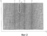
Фиг.2 - диаграмма, которая представляет параметры частотного спектра динамического сигнала давления, определенные согласно форме выполнения изобретения; иFigure 2 is a diagram that represents the frequency spectrum parameters of a dynamic pressure signal determined according to an embodiment of the invention; and
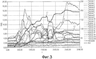
Фиг.3 - представление, которое изображает изменение во времени определенных в варианте выполнения изобретения среднеквадратичных значений сигнала давления газовой турбины в зависимости от изменяющейся нагрузки и положения направляющих лопаток.Figure 3 is a view that depicts the time variation of the rms values of the gas turbine pressure signal determined in an embodiment of the invention, depending on the changing load and position of the guide vanes.
Фиг.1 показывает блок-схему, отображающую основные этапы способа формы выполнения соответствующего изобретению способа контроля функционирования газовой турбины. В форме выполнения по фиг.1 контролируется газовая турбина, конструкция которой сама по себе известна и поэтому описывается лишь кратко. Газовая турбина содержит многоступенчатый осевой компрессор 2 с несколькими рабочими дисками и рядами направляющих лопаток, причем в компрессоре выполнено множество компрессорных ступеней с направляющими лопатками и рабочими лопатками. Посредством направляющей лопатки устанавливается угол потока воздуха в компрессоре на рабочую лопатку, и рабочая лопатка сжимает и накачивает воздух дальше. К многоступенчатому осевому компрессору 2 в турбине примыкает камера сгорания, в которой сжигается соответствующее топливо с помощью подводимого через компрессор воздуха, посредством чего турбина приводится в действие.Figure 1 shows a flowchart showing the main steps of a method for performing a method of controlling the functioning of a gas turbine according to the invention. In the embodiment of FIG. 1, a gas turbine is controlled, the construction of which is known per se and therefore is described only briefly. The gas turbine contains a multistage axial compressor 2 with several working disks and rows of guide vanes, and the compressor has many compressor stages with guide vanes and rotor blades. By means of the guide vane, the angle of air flow in the compressor is set to the working blade, and the working blade compresses and pumps air further. A multi-stage axial compressor 2 in the turbine is adjoined by a combustion chamber in which the corresponding fuel is burned by means of air supplied through the compressor, whereby the turbine is driven.
В показанной на фиг.1 турбине предусмотрено множество датчиков, которые определяют соответствующие рабочие параметры турбины. Датчик 4 является датчиком температуры, который измеряет окружающую температуру и выдает соответствующий измеренный сигнал V1. Датчик 5 является датчиком давления, который измеряет давление воздуха в окружающей среде и выдает соответствующий измеренный сигнал V2. Ссылочной позицией 6 обозначен датчик влажности, который измеряет влажность воздуха и выдает соответствующий измеренный сигнал V3. Кроме того, предусмотрен датчик 7, который на входе компрессора измеряет положение имеющихся там регулируемых направляющих лопаток, причем положение направляющих лопаток в газовой турбине может изменяться с помощью соответствующего регулирующего устройства. Измеренное значение положения направляющих лопаток на фиг.1 обозначено как V4.In the turbine shown in FIG. 1, a plurality of sensors are provided that determine the respective operating parameters of the turbine. Sensor 4 is a temperature sensor that measures the ambient temperature and provides a corresponding measured signal V1. Sensor 5 is a pressure sensor that measures the air pressure in the environment and provides a corresponding measured signal V2. Reference numeral 6 denotes a humidity sensor that measures air humidity and provides a corresponding measured signal V3. In addition, a sensor 7 is provided which, at the compressor inlet, measures the position of the adjustable guide vanes there, the position of the guide vanes in the gas turbine can be changed using an appropriate control device. The measured value of the position of the guide vanes in figure 1 is indicated as V4.
Наконец на выходе компрессора предусмотрен датчик 8 давления, который динамически измеряет давление на выходе компрессора в форме измеренного сигнала V5. При этом «динамически» означает, что определяется изменение во времени звукового давления с соответствующей частотой выборки, так что определяется временной режим давления. Измерение, в особенности, является динамическим в том случае, если частота выборки лежит в диапазоне кГц и выше. Измеренный сигнал давления возникает при этом за счет того, что в отдельных компрессорных ступенях при работе рабочая лопатка компрессора проходит мимо направляющей лопатки и тем самым генерируются периодические волны давления в сжатом воздухе, причем период волны давления зависит от числа направляющих и рабочих лопаток соответствующей компрессорной ступени. Определенный динамический сигнал давления содержит, таким образом, ввиду множества компрессорных ступеней, множество периодических составляющих.Finally, a pressure sensor 8 is provided at the compressor output, which dynamically measures the pressure at the compressor output in the form of a measured signal V5. In this case, “dynamically” means that the change in time of sound pressure with the corresponding sampling frequency is determined, so that the temporal mode of pressure is determined. The measurement, in particular, is dynamic if the sampling frequency lies in the range of kHz and higher. In this case, the measured pressure signal arises due to the fact that in the individual compressor stages during operation the compressor working blade passes by the guide vane and thereby periodic pressure waves in compressed air are generated, and the pressure wave period depends on the number of guide and working vanes of the corresponding compressor stage. A certain dynamic pressure signal thus comprises, in view of the plurality of compressor stages, a plurality of periodic components.
Вместо применения единственного датчика 8 давления может также использоваться несколько датчиков давления, в частности, для измерений могут привлекаться уже имеющиеся датчики давления, которые во многих турбинах используются в зоне горения для контроля стабильности горения. Иначе может применяться установка датчика давления в выходном диффузоре или в зоне воздухозаборника компрессора газовой турбины. В соответствии с изобретением сигнал V5 сначала на этапе S1 подвергается аналого-цифровому (A/D) преобразованию, и с оцифрованным сигналом затем на этапе S2 выполняется быстрое преобразование Фурье (FFT) для определения частотного спектра сигнала. Выполняемое на этапе S2 FFT-преобразование при этом настолько точно настраивается на частоты, получающиеся из числа оборотов газовой турбины и числа направляющих и рабочих лопаток, что отдельные частоты четко по отдельности могут быть соотнесены с компрессорными ступенями. В качестве результата FFT-преобразования получают характеристические частотные полосы с соответствующими амплитудами отдельных частот.Instead of using a single pressure sensor 8, several pressure sensors can also be used, in particular, existing pressure sensors, which in many turbines are used in the combustion zone to control combustion stability, can be used for measurements. Otherwise, the installation of a pressure sensor in the outlet diffuser or in the area of the air intake of the gas turbine compressor may be used. In accordance with the invention, the signal V5 is first subjected to analog-to-digital (A / D) conversion in step S1, and then, in step S2, the fast Fourier transform (FFT) is performed to determine the frequency spectrum of the signal in step S2. The FFT conversion performed in step S2 is so precisely tuned to the frequencies obtained from the number of revolutions of the gas turbine and the number of guide and rotor blades that the individual frequencies can be clearly separately correlated with the compressor stages. As a result of the FFT transform, characteristic frequency bands with corresponding amplitudes of individual frequencies are obtained.
Подобный частотный спектр показан для примера на диаграмме на фиг.2. Эта диаграмма обозначается как диаграмма Кэмпбелла (Campbell). По оси абсцисс показаны частоты f в сигнале давления, а по оси ординат - время t. Амплитуда отдельных частот на фиг.2 имеет цветовой код, причем ввиду черно-белого представления это цветовое кодирование не видно. Обычно красный цвет используется для индикации высоких амплитуд. Для примера на фиг.2 отмечен диапазон В, в котором имеются высокие амплитуды. В представлении на фиг.2 по времени t имело место изменение определенных рабочих параметров турбины. В частности, изменялась нагрузка и положение направляющих лопаток компрессора. Отсюда получаются изменяющиеся амплитуды, причем, однако, характеристические частотные полосы по времени остаются прежними. Особенно явно видны на фиг.2 частотные полросы F1, F2, F3 и F4. Каждая из частотных полос с F1 по F4 представляет при этом компрессорную ступень осевого компрессора 2 газовой турбины 1, то есть с каждой компрессорной ступенью при функционировании с определенным числом оборотов соотносится частотная полоса с характеристической частотой.A similar frequency spectrum is shown as an example in the diagram in figure 2. This chart is referred to as the Campbell chart. The abscissa shows the frequencies f in the pressure signal, and the ordinate shows the time t. The amplitude of the individual frequencies in figure 2 has a color code, and due to the black and white representation, this color coding is not visible. Typically, red is used to indicate high amplitudes. For example, in figure 2 marked range In which there are high amplitudes. In the representation of FIG. 2, at time t, there was a change in certain turbine operating parameters. In particular, the load and position of the compressor guide vanes changed. From this, varying amplitudes are obtained, however, however, the characteristic frequency bands in time remain the same. In FIG. 2, frequency polls F1, F2, F3 and F4 are especially clearly visible. Each of the frequency bands F1 through F4 represents the compressor stage of the axial compressor 2 of the gas turbine 1, that is, the frequency band with the characteristic frequency is associated with each compressor stage when operating with a certain speed.
Согласно этапу S3 по фиг.1 затем осуществляется оценка показанных на фиг.2 частотных полос, причем, при необходимости, осуществляется коррекция с помощью соответствующей модели. На этапе S3 для каждой частотной полосы посредством интегрирования по частотам полосы определяется доля энергии сигнала давления в соответствующей частотной полосе, причем эта доля энергии выдается как так называемое среднеквадратичное (RMS) значение. Это RMS-значение является параметром, хорошо известным специалисту. В качестве результата этапа S3 получают, таким образом, для каждой компрессорной ступени характеристическое RMS-значение, причем на фиг.1 для примера представлены четыре RMS-значения от R1 до R4 для четырех компрессорных ступеней.According to step S3 of FIG. 1, then the frequency bands shown in FIG. 2 are evaluated, and, if necessary, a correction is performed using the corresponding model. In step S3, for each frequency band, by integrating over the frequency of the band, a fraction of the energy of the pressure signal in the corresponding frequency band is determined, moreover, this fraction of the energy is generated as the so-called RMS value. This RMS value is a parameter well known to one skilled in the art. As a result of step S3, thus, a characteristic RMS value is obtained for each compressor stage, and in Fig. 1, for example, four RMS values from R1 to R4 for four compressor stages are presented.
Фиг.3 еще раз показывает на соответствующей диаграмме временное представление RMS-значений в турбине с 20 характеристическими частотными полосами, которые соотнесены с соответствующей одной компрессорной ступенью компрессора газовой турбины. Вдоль оси абсцисс здесь нанесено время в секундах, а вдоль оси ординат - соответствующие RMS-значения отдельных полос. Диаграмма также имеет цветовой код, причем каждая полоса представлена другим цветом, что, однако, ввиду черно-белого представления на фиг.3 не видно. При этом отдельные частотные полосы от полосы 1 до полосы 20 изображены на диаграмме на условных обозначениях справа. Наряду с RMS-значениями диаграмма на фиг.3 содержит также осуществляемое во время работы турбины изменение нагрузки и положения направляющих лопаток. Это показано посредством соответствующих линий с обозначением «нагрузка» для нагрузки и “IGV” для направляющих лопаток на условных обозначениях. Для заметности соответствующего графика линии временного изменения нагрузки обозначены посредством L1, а положения направляющих лопаток - посредством L2. Отдельные значения для нагрузки или положения направляющих лопаток при этом представлены как пропорциональные значения посредством ординаты на правом краю диаграммы.Figure 3 once again shows in a corresponding diagram a temporary representation of RMS values in a turbine with 20 characteristic frequency bands that are associated with the corresponding single compressor stage of a gas turbine compressor. The time in seconds is plotted along the abscissa, and the corresponding RMS values of the individual bands are plotted along the ordinate. The diagram also has a color code, with each bar represented by a different color, which, however, is not visible due to the black and white representation in FIG. In this case, individual frequency bands from band 1 to band 20 are shown in the diagram on the legend on the right. Along with the RMS values, the diagram in FIG. 3 also includes a change in the load and position of the guide vanes during operation of the turbine. This is shown by means of the corresponding lines with the designation “load” for the load and “IGV” for the guide vanes on the legend. For noticeability of the corresponding graph, the lines of temporary changes in the load are indicated by L1, and the positions of the guide vanes by L2. The individual values for the load or position of the guide vanes are then presented as proportional values by the ordinate on the right edge of the diagram.
Из фиг.3 можно видеть, что при изменении мощности, что достигается изменением массового потока компрессора, получаются очень четкие отклики в RMS-значениях даже при незначительном изменении массового потока. С другой стороны, также видно, что комплексные отклики системы могут быть получены в зависимости от рабочего состояния. С помощью RMS-значений в комбинации с другими рабочими параметрами, из которых на фиг.3 показаны нагрузка и положение направляющих лопаток, можно в соответствии с изобретением сделать вывод относительно отклоняющегося от нормального состояния газовой турбины или компрессора.From Fig. 3 it can be seen that when the power changes, which is achieved by changing the mass flow of the compressor, very clear responses are obtained in RMS values even with a slight change in the mass flow. On the other hand, it is also seen that the complex responses of the system can be obtained depending on the operating state. Using RMS values in combination with other operating parameters, from which the load and position of the guide vanes are shown in FIG. 3, it is possible in accordance with the invention to conclude that a gas turbine or compressor deviates from the normal state.
Для того чтобы из измеренных рабочих параметров, а также из RMS-значений соответствующим образом вывести показатель диагностики, в соответствии с изобретением используются нейронные сети. В описываемой здесь форме выполнения изобретения применяется нейронная модель, предпочтительно базирующаяся на радиальных базисных функциях, которая известна также как RBF-сеть. Принципиальная структура таких сетей хорошо известна из уровня техники, и поэтому здесь детально не поясняется. Такие сети состоят из слоя ввода и вывода и изучают параметры из радиальных базисных функций, например гауссовых функций, на основе входных величин в слое ввода, чтобы отсюда аппроксимировать функциональное поведение и распределение входных величин. В описываемой здесь форме выполнения для каждой компрессорной ступени соответствующая RBF-сеть обучалась на рабочих параметрах, а также соответствующих RMS-значениях компрессорной ступени, причем обучение проводилось на основе измерений в нормальном режиме работы газовой турбины.In order to derive a diagnostic indicator from the measured operating parameters, as well as from the RMS values, neural networks are used in accordance with the invention. In the embodiment described herein, a neural model is used, preferably based on radial basis functions, which is also known as an RBF network. The basic structure of such networks is well known in the art and therefore is not explained in detail here. Such networks consist of an input and output layer and study the parameters from radial basis functions, for example, Gaussian functions, based on the input values in the input layer, from here to approximate the functional behavior and distribution of input values. In the embodiment described here, for each compressor stage, the corresponding RBF network was trained on the operating parameters, as well as the corresponding RMS values of the compressor stage, and the training was based on measurements in the normal operation of a gas turbine.
Отдельные RBF-сети вырабатывают в качестве выходной величины нормированное между 0 и 1 доверительное значение, которое для набора входных величин, то есть для имеющихся в определенный момент времени рабочих параметров и соответствующего RMS-значения, показывает насколько высока вероятность того, что в нормальном режиме работы возникнет такая комбинация из RMS-значения и рабочих параметров. Чем выше это доверительное значение, тем вероятнее имеет место фактически нормальный режим работы. Напротив, малые доверительные значения означают, что с высокой вероятностью имеет место работа со сбоями в соответствующем компрессоре газовой турбины.Individual RBF networks generate a confidence value normalized between 0 and 1, which for a set of input values, that is, for operating parameters available at a certain point in time and the corresponding RMS value, shows how high the probability is that in normal operation this combination of RMS value and operating parameters will occur. The higher this confidence value, the more likely the actual normal mode of operation takes place. On the contrary, low confidence values mean that there is a high probability of malfunctioning in the corresponding gas turbine compressor.
Соответственно обученные нейронные сети функционируют как аппроксимативные инкапсуляторы данных, и на этапе S4 по фиг.1 получают в качестве входных величин отдельные рабочие параметры согласно измеренным сигналам V1-V4 и RMS-значения R1-R4. Этап S4 для примера разделен на три подэтапа S401, S402 и S403. На этапе S401 рабочие параметры и RMS-значения R1 и R2 подаются в соответствующие нейронные сети соответствующей компрессорной ступени. На этапе S402 RMS-значение R3 и на этапе S403 RMS-значение R4 подаются в нейронную сеть соответствующей компрессорной ступени. В качестве результата этапа S4 получают для каждой нейронной сети соответствующее доверительное значение в диапазоне значений от 0 до 1. При этом для доверительного значения между 0,5 и 1 мог бы быть сделан вывод, что имеет место нормальный режим работы, в то время как для доверительного значения менее 0,5 диагностируется, что имеет место режим работы со сбоями. Эти диагностические значения выдаются на этапе S5. При выборе рабочих параметров в качестве входных величин для нейронных сетей при этом не требуется, чтобы отдельные параметры находились в однозначной взаимосвязи. Напротив, каждое распределение комбинаций параметров может изучаться, если в распоряжении имеется достаточно рабочих данных для обучения нейронных моделей. Для высокой избирательности при распознавании необычных состояний является целесообразным все параметры, оказывающие заметное влияние на систему, использовать в качестве входных величин при обучении нейронной сети.Accordingly, trained neural networks function as approximative data encapsulators, and in step S4 of FIG. 1, individual operating parameters are obtained as input values according to the measured signals V1-V4 and RMS values R1-R4. Step S4 for example is divided into three sub-steps S401, S402, and S403. At step S401, the operating parameters and RMS values R1 and R2 are supplied to the respective neural networks of the corresponding compressor stage. In step S402, the RMS value of R3 and in step S403 the RMS value of R4 are supplied to the neural network of the corresponding compressor stage. As a result of step S4, for each neural network, a corresponding confidence value is obtained in the range of values from 0 to 1. At the same time, for a confidence value between 0.5 and 1, it could be concluded that normal operation occurs, while for a confidence value of less than 0.5 is diagnosed, which is the malfunction mode. These diagnostic values are output in step S5. When choosing operating parameters as input values for neural networks, it is not required that the individual parameters are in an unambiguous relationship. In contrast, each distribution of parameter combinations can be studied if sufficient working data are available to train neural models. For high selectivity in recognizing unusual states, it is advisable to use all parameters that have a noticeable effect on the system as input values for training a neural network.
В итоге по вышеописанному способу для характеристических значений энергии частотных полос каждой компрессорной ступени один или несколько инкапсуляторов данных в форме RBF-сетей обучаются на широком спектре различных комбинаций параметров, причем обученные инкапсуляторы данных затем используются для контроля газовой турбины, чтобы обнаруживать режим работы со сбоями. В качестве параметров при обучении или контроле газовой турбины принимаются во внимание, в частности, число оборотов, нагрузка, положение направляющих лопаток, давление воздуха, давление окружающей среды, влажность воздуха и т.п. Эти величины наряду с амплитудами энергий характеристических частот представляют собой важные входные величины инкапсуляторов данных. Дополнительно может использоваться отношение RMS-значений характеристических частот к их высшим гармоникам в более высокочастотных полосах. Кроме того, в одной форме выполнения соответствующего изобретению способа доверительные значения отдельных инкапсуляторов данных могут объединяться. Тем самым можно, например, определить общую достоверность наличия нормального режима работы. Это может, в частности, осуществляться на основе правил нечеткой логики или дискретных правил, которые выражают известные взаимосвязи для поведения и взаимодействия отдельных компрессорных ступеней. В результате можно с помощью описанной здесь формы выполнения соответствующего изобретению способа на основе измеренных значений небольшого числа датчиков давления диагностировать качество и состояние отдельных компрессорных ступеней осевого компрессора газовой турбины.As a result, according to the method described above, for characteristic energy values of the frequency bands of each compressor stage, one or more data encapsulators in the form of RBF networks are trained on a wide range of different combinations of parameters, and the trained data encapsulators are then used to control the gas turbine to detect a malfunction mode. As parameters when training or monitoring a gas turbine, it is taken into account, in particular, the number of revolutions, load, position of the guide vanes, air pressure, ambient pressure, air humidity, etc. These values, along with the amplitudes of the energies of the characteristic frequencies, represent important input values of the data encapsulators. Additionally, the ratio of the RMS values of the characteristic frequencies to their higher harmonics in higher frequency bands can be used. In addition, in one embodiment of the method of the invention, the confidence values of the individual data encapsulators may be combined. Thus, it is possible, for example, to determine the overall reliability of the presence of a normal mode of operation. This can, in particular, be carried out on the basis of fuzzy logic rules or discrete rules that express known relationships for the behavior and interaction of individual compressor stages. As a result, it is possible to diagnose the quality and condition of the individual compressor stages of the axial compressor of a gas turbine using the described embodiment of the method according to the invention, based on the measured values of a small number of pressure sensors.
С помощью соответствующего изобретению способа обеспечивается ряд преимуществ. В частности, уже при незначительном количестве датчиков давления, например, уже с одним датчиком давления для всего компрессора может диагностироваться состояние компрессора, что снижает общие затраты на контроль функционирования газовой турбины. Кроме того, соответствующий изобретению способ может быть просто согласован с различными газовыми турбинами за счет того, что конкретно для данной газовой турбины сначала в режиме обучения нейронные сети обучаются, а затем на основе таких обученных сетей выполняется контроль газовой турбины. Кроме того, с помощью соответствующего изобретению способа возможен быстрый и высокочастотный контроль всего компрессора газовой турбины во время работы, причем обеспечивается возможность получения долговременной информации для срока службы газовой турбины. Кроме того, могут также распознаваться скрытые изменения по отношению к нормальному режиму работы газовой турбины посредством определения доверительных значений в течение длительного времени. Тем самым можно снизить затраты на техническое обслуживание, так как посредством соответствующей изобретению диагностики повреждения обнаруживаются своевременно, и тем самым могут проводиться соответствующие обнаруженным повреждениям мероприятия по ремонту вместо того, чтобы проводить ремонт с жестко установленными интервалами или чисто профилактически.Using the method according to the invention provides several advantages. In particular, even with a small number of pressure sensors, for example, already with one pressure sensor for the entire compressor, the condition of the compressor can be diagnosed, which reduces the overall cost of monitoring the operation of a gas turbine. In addition, the method according to the invention can simply be matched with various gas turbines due to the fact that specifically for a given gas turbine, neural networks are trained first in the training mode, and then the gas turbine is controlled based on such trained networks. In addition, using the method of the invention, quick and high-frequency monitoring of the entire gas turbine compressor is possible during operation, and it is possible to obtain long-term information for the life of the gas turbine. In addition, latent changes with respect to the normal operation of the gas turbine can also be recognized by determining confidence values over time. Thereby, it is possible to reduce maintenance costs, since by means of the diagnosis according to the invention, damage is detected in a timely manner, and thereby repair measures corresponding to the detected damage can be carried out instead of having to carry out repairs at fixed intervals or purely prophylactically.
Claims (28)
при котором одна или более нейронных сетей обучаются, базируясь на нормальном режиме работы газовой турбины (1), при этом
измеряется, по меньшей мере, один динамический сигнал (V5) давления посредством, по меньшей мере, одного датчика (8) давления в или на компрессоре (2) газовой турбины (1), а также измеряется один или более рабочих параметров (V1, V2, V3, V4) газовой турбины (1) с помощью одного или более других датчиков (4, 5, 6, 7) при нормальном режиме работы газовой турбины (1), и/или считываются динамический сигнал (V5) давления, а также один или более рабочих параметров (V1, V2, V3, V4) газовой турбины (1), которые были измерены в нормальном режиме работы газовой турбины (1);
динамический сигнал (V5) давления подвергается частотному анализу, посредством чего определяются один или более параметров частотного спектра сигнала (V5) давления;
базируясь на одном или более измеренных рабочих параметрах (VI, V2, V3, V4) и одном или более параметрах частотного спектра сигнала (V5) давления, обучаются одна или более нейронных сетей, которые в качестве входных величин имеют один или более измеренных рабочих параметров (VI, V2, V3, V4) и один или более параметров частотного спектра сигнала (V5) давления, а в качестве выходной величины имеют, по меньшей мере, один показатель диагностики, который представляет меру вероятности для наличия нормального режима работы газовой турбины (1) в зависимости от входных величин,
отличающийся тем, что в качестве параметра частотного спектра для каждой компрессорной ступени определяется характеристическая частотная полоса (F1, F2, F3, F4) на основе числа оборотов газовой турбины и числа направляющих лопаток и рабочих лопаток соответствующей компрессорной ступени, и для каждой характеристической частотной полосы вычисляется содержащаяся в ней доля энергии сигнала (V5) давления, в частности среднеквадратичное значение, и/или амплитудный максимум и/или несколько смежных амплитудных максимумов частотных составляющих внутри характеристической частотной полосы (F1, F2, F3, F4) для применения в качестве входных величин одной или более нейронных сетей.1. A method of analyzing the operation of a multi-stage compressor (2) of a gas turbine (1) with a number of compressor stages,
in which one or more neural networks are trained based on the normal operation of a gas turbine (1), while
at least one dynamic pressure signal (V5) is measured by means of at least one pressure sensor (8) in or on the compressor (2) of the gas turbine (1), and one or more operating parameters is measured (V1, V2 , V3, V4) of the gas turbine (1) using one or more other sensors (4, 5, 6, 7) during normal operation of the gas turbine (1), and / or a dynamic pressure signal (V5) is read, as well as one or more operating parameters (V1, V2, V3, V4) of the gas turbine (1), which were measured in the normal operation of the gas turbine (1);
a dynamic pressure signal (V5) is subjected to frequency analysis, whereby one or more parameters of the frequency spectrum of the pressure signal (V5) are determined;
based on one or more measured operating parameters (VI, V2, V3, V4) and one or more parameters of the frequency spectrum of the pressure signal (V5), one or more neural networks are trained that have one or more measured operating parameters as input values ( VI, V2, V3, V4) and one or more parameters of the frequency spectrum of the pressure signal (V5), and as an output quantity have at least one diagnostic indicator, which is a measure of the probability for the normal operation of a gas turbine (1) depending on input values
characterized in that as a parameter of the frequency spectrum for each compressor stage, a characteristic frequency band (F1, F2, F3, F4) is determined based on the number of revolutions of the gas turbine and the number of guide vanes and rotor blades of the corresponding compressor stage, and for each characteristic frequency band is calculated the fraction of the energy of the pressure signal (V5) contained in it, in particular the rms value, and / or the amplitude maximum and / or several adjacent amplitude maxima of the frequency components in the morning of the characteristic frequency band (F1, F2, F3, F4) for use as input values of one or more neural networks.
причем этот показатель диагностики представляет меру вероятности наличия нормального режима работы соответствующей компрессорной ступени в зависимости от входных величин.6. The method according to claim 1 or 2, in which a neural network is trained for each compressor stage, the corresponding neural network having frequency spectrum parameters related to the characteristic frequency band (F1, F2, F3, F4) as input values, and wherein each neural network has a diagnostic indicator as an output quantity,
moreover, this diagnostic indicator is a measure of the likelihood of a normal mode of operation of the corresponding compressor stage, depending on the input values.
причем этот показатель диагностики представляет меру вероятности наличия нормального режима работы соответствующей компрессорной ступени в зависимости от входных величин.7. The method according to claim 3, in which a neural network is trained for each compressor stage, the corresponding neural network having frequency spectrum parameters as input values related to the characteristic frequency band (F1, F2, F3, F4), and each neural the network has a diagnostic indicator as an output quantity,
moreover, this diagnostic indicator is a measure of the likelihood of a normal mode of operation of the corresponding compressor stage, depending on the input values.
причем этот показатель диагностики представляет меру вероятности наличия нормального режима работы соответствующей компрессорной ступени в зависимости от входных величин.8. The method according to claim 5, in which a neural network is trained for each compressor stage, the corresponding neural network having frequency spectrum parameters related to the characteristic frequency band (F1, F2, F3, F4) as input values, and each neural network the network has a diagnostic indicator as an output quantity,
moreover, this diagnostic indicator is a measure of the likelihood of a normal mode of operation of the corresponding compressor stage, depending on the input values.
число оборотов газовой турбины (1),
нагрузка газовой турбины (1),
давление окружающей среды,
температура окружающей среды,
влажность воздуха,
положение направляющих лопаток на компрессоре (2) газовой турбины (1).16. The method according to claim 1 or 2, in which one or more of the following parameters are measured or read as operating parameters (VI, V2, V3, V4):
the speed of the gas turbine (1),
gas turbine load (1),
environmental pressure
ambient temperature
air humidity,
position of the guide vanes on the compressor (2) of the gas turbine (1).
число оборотов газовой турбины (1),
нагрузка газовой турбины (1),
давление окружающей среды,
температура окружающей среды,
влажность воздуха,
положение направляющих лопаток на компрессоре (2) газовой турбины (1).17. The method according to claim 3, in which one or more of the following parameters are measured or read as operating parameters (V1, V2, V3, V4):
the speed of the gas turbine (1),
gas turbine load (1),
environmental pressure
ambient temperature
air humidity,
position of the guide vanes on the compressor (2) of the gas turbine (1).
число оборотов газовой турбины (1),
нагрузка газовой турбины (1),
давление окружающей среды,
температура окружающей среды,
влажность воздуха,
положение направляющих лопаток на компрессоре (2) газовой турбины (1).18. The method according to any one of claims 5, 7, 8, 9, 12, 13 or 15, in which one or more of the following parameters are measured or read as operating parameters (V1, V2, V3, V4):
the speed of the gas turbine (1),
gas turbine load (1),
environmental pressure
ambient temperature
air humidity,
position of the guide vanes on the compressor (2) of the gas turbine (1).
число оборотов газовой турбины (1),
нагрузка газовой турбины (1),
давление окружающей среды,
температура окружающей среды,
влажность воздуха,
положение направляющих лопаток на компрессоре (2) газовой турбины (1).19. The method according to claim 4, in which one or more of the following parameters are measured or read as operating parameters (V1, V2, V3, V4):
the speed of the gas turbine (1),
gas turbine load (1),
environmental pressure
ambient temperature
air humidity,
position of the guide vanes on the compressor (2) of the gas turbine (1).
число оборотов газовой турбины (1),
нагрузка газовой турбины (1),
давление окружающей среды,
температура окружающей среды,
влажность воздуха,
положение направляющих лопаток на компрессоре (2) газовой турбины (1).20. The method according to claim 6, in which one or more of the following parameters are measured or read as operating parameters (V1, V2, V3, V4):
the speed of the gas turbine (1),
gas turbine load (1),
environmental pressure
ambient temperature
air humidity,
position of the guide vanes on the compressor (2) of the gas turbine (1).
измеряется, по меньшей мере, один динамический сигнал (V5) давления, по меньшей мере, одним датчиком (8) давления в или на компрессоре (2) газовой турбины (1), а также измеряются один или несколько рабочих параметров (V1, V2, V3, V4) газовой турбины (1) посредством других датчиков (4, 5, 6, 7) при нормальном режиме работы газовой турбины (1);
динамический сигнал (V5) давления подвергается частотному анализу, благодаря чему определяется один или более параметров частотного спектра сигнала (V5) давления;
один или более измеренных рабочих параметров (V1, V2, V3, V4) и один или более параметров частотного спектра сигнала (V5) давления подаются в качестве входных величин в одну или более обученных нейронных сетей, а в качестве выходной величины одной или более нейронных сетей выдается, по меньшей мере, один показатель диагностики.25. The method of monitoring a gas turbine (1), based on one or more neural networks trained according to the method according to any one of claims 1 to 23, in which during operation of the gas turbine:
at least one dynamic pressure signal (V5) is measured by at least one pressure sensor (8) in or on the compressor (2) of the gas turbine (1), and one or more operating parameters are measured (V1, V2, V3, V4) of the gas turbine (1) by other sensors (4, 5, 6, 7) during normal operation of the gas turbine (1);
the dynamic pressure signal (V5) is subjected to frequency analysis, whereby one or more parameters of the frequency spectrum of the pressure signal (V5) are determined;
one or more measured operating parameters (V1, V2, V3, V4) and one or more parameters of the frequency spectrum of the pressure signal (V5) are supplied as input values to one or more trained neural networks, and as an output value of one or more neural networks at least one diagnostic indicator is issued.
по меньшей мере, один датчик (8) давления для измерения, по меньшей мере, одного динамического сигнала (V5) давления в или на компрессоре (2) газовой турбины (1), а также один или несколько других датчиков для измерения одного или более рабочих параметров (V1, V2, V3, V4) газовой турбины (1) при функционировании газовой турбины (1);
устройство частотного анализа, посредством которого динамический сигнал (V5) давления может подвергаться частотному анализу, благодаря чему определяется один или более параметров частотного спектра сигнала (V5) давления;
одну или более обученных нейронных сетей, которые были обучены, и на которые в качестве входных величин могут подаваться один или более измеренных рабочих параметров (VI, V2, V3, V4) и один или более параметров частотного спектра сигнала (V5) давления, и которые в качестве выходных величин могут выдавать, по меньшей мере, один показатель диагностики.27. A device for monitoring a gas turbine (1), containing one or more trained neural networks implementing the method according to any one of claims 1 to 23, comprising:
at least one pressure sensor (8) for measuring at least one dynamic pressure signal (V5) in or on the compressor (2) of the gas turbine (1), as well as one or more other sensors for measuring one or more working parameters (V1, V2, V3, V4) of the gas turbine (1) during the operation of the gas turbine (1);
a frequency analysis device by which the dynamic pressure signal (V5) can be subjected to frequency analysis, whereby one or more parameters of the frequency spectrum of the pressure signal (V5) are determined;
one or more trained neural networks that have been trained, and to which one or more measured operating parameters (VI, V2, V3, V4) and one or more parameters of the frequency spectrum of the pressure signal (V5) can be input, and which at least one diagnostic indicator may be output as output values.
Applications Claiming Priority (3)
| Application Number | Priority Date | Filing Date | Title |
|---|---|---|---|
| EP07021041A EP2053475A1 (en) | 2007-10-26 | 2007-10-26 | Method for analysing the operation of a gas turbine |
| EP07021041.4 | 2007-10-26 | ||
| PCT/EP2008/062538 WO2009053183A2 (en) | 2007-10-26 | 2008-09-19 | Method for analyzing the operation of a gas turbine |
Publications (2)
| Publication Number | Publication Date |
|---|---|
| RU2010121150A RU2010121150A (en) | 2011-12-10 |
| RU2480806C2 true RU2480806C2 (en) | 2013-04-27 |
Family
ID=39431230
Family Applications (1)
| Application Number | Title | Priority Date | Filing Date |
|---|---|---|---|
| RU2010121150/08A RU2480806C2 (en) | 2007-10-26 | 2008-09-19 | Gas turbine operation analysis method |
Country Status (8)
| Country | Link |
|---|---|
| US (1) | US8396689B2 (en) |
| EP (2) | EP2053475A1 (en) |
| JP (1) | JP5393693B2 (en) |
| CN (1) | CN101836168B (en) |
| CA (1) | CA2703586C (en) |
| RU (1) | RU2480806C2 (en) |
| TW (1) | TWI370201B (en) |
| WO (1) | WO2009053183A2 (en) |
Cited By (1)
| Publication number | Priority date | Publication date | Assignee | Title |
|---|---|---|---|---|
| RU2725299C1 (en) * | 2020-01-29 | 2020-06-30 | Федеральное государственное унитарное предприятие "Центральный институт авиационного моторостроения имени П.И. Баранова" | Method of estimating technical condition of turbine blades of a gas-turbine engine |
Families Citing this family (40)
| Publication number | Priority date | Publication date | Assignee | Title |
|---|---|---|---|---|
| US10089443B2 (en) | 2012-05-15 | 2018-10-02 | Baxter International Inc. | Home medical device systems and methods for therapy prescription and tracking, servicing and inventory |
| US9267443B2 (en) | 2009-05-08 | 2016-02-23 | Gas Turbine Efficiency Sweden Ab | Automated tuning of gas turbine combustion systems |
| US9671797B2 (en) | 2009-05-08 | 2017-06-06 | Gas Turbine Efficiency Sweden Ab | Optimization of gas turbine combustion systems low load performance on simple cycle and heat recovery steam generator applications |
| US9354618B2 (en) | 2009-05-08 | 2016-05-31 | Gas Turbine Efficiency Sweden Ab | Automated tuning of multiple fuel gas turbine combustion systems |
| US8437941B2 (en) * | 2009-05-08 | 2013-05-07 | Gas Turbine Efficiency Sweden Ab | Automated tuning of gas turbine combustion systems |
| US8135568B2 (en) | 2010-06-25 | 2012-03-13 | General Electric Company | Turbomachine airfoil life management system and method |
| CN102063109B (en) * | 2010-11-29 | 2012-09-05 | 株洲南车时代电气股份有限公司 | Neural network-based subway train fault diagnosis device and method |
| WO2012076427A1 (en) | 2010-12-09 | 2012-06-14 | Basf Se | Method and device for the model-based monitoring of a turbomachine |
| ITCO20120008A1 (en) * | 2012-03-01 | 2013-09-02 | Nuovo Pignone Srl | METHOD AND SYSTEM FOR MONITORING THE CONDITION OF A GROUP OF PLANTS |
| US9212946B2 (en) * | 2012-06-08 | 2015-12-15 | General Electric Company | Campbell diagram displays and methods and systems for implementing same |
| EP2706422B1 (en) | 2012-09-11 | 2016-07-27 | Siemens Aktiengesellschaft | Method for computer-implemented monitoring of the operation of a technical system, in particular an electrical energy production assembly |
| US20150159867A1 (en) * | 2013-12-05 | 2015-06-11 | General Electric Company | System and Method for Assessing Combustor Health During Operation |
| US9500563B2 (en) * | 2013-12-05 | 2016-11-22 | General Electric Company | System and method for detecting an at-fault combustor |
| DE102013226049A1 (en) | 2013-12-16 | 2015-06-18 | Siemens Aktiengesellschaft | Device and method for detecting the current state of damage of a machine |
| EP2996001A1 (en) * | 2014-09-10 | 2016-03-16 | Siemens Aktiengesellschaft | Method for computer-based analysis of a data set from observations |
| EP3064744B1 (en) | 2015-03-04 | 2017-11-22 | MTU Aero Engines GmbH | Diagnosis of gas turbine aircraft engines |
| US20160363127A1 (en) * | 2015-06-09 | 2016-12-15 | General Electric Company | Systems and methods for monitoring a compressor |
| EP3356736B1 (en) | 2015-09-28 | 2022-08-10 | Services Pétroliers Schlumberger | Burner monitoring and control systems |
| US10809156B2 (en) | 2016-02-15 | 2020-10-20 | General Electric Company | Automated system and method for generating engine test cell analytics and diagnostics |
| US11327475B2 (en) | 2016-05-09 | 2022-05-10 | Strong Force Iot Portfolio 2016, Llc | Methods and systems for intelligent collection and analysis of vehicle data |
| US20180284758A1 (en) | 2016-05-09 | 2018-10-04 | StrongForce IoT Portfolio 2016, LLC | Methods and systems for industrial internet of things data collection for equipment analysis in an upstream oil and gas environment |
| US10983507B2 (en) | 2016-05-09 | 2021-04-20 | Strong Force Iot Portfolio 2016, Llc | Method for data collection and frequency analysis with self-organization functionality |
| WO2019028269A2 (en) | 2017-08-02 | 2019-02-07 | Strong Force Iot Portfolio 2016, Llc | Methods and systems for detection in an industrial internet of things data collection environment with large data sets |
| US11774944B2 (en) | 2016-05-09 | 2023-10-03 | Strong Force Iot Portfolio 2016, Llc | Methods and systems for the industrial internet of things |
| CN114625076A (en) | 2016-05-09 | 2022-06-14 | 强力物联网投资组合2016有限公司 | Method and system for industrial internet of things |
| US11686212B2 (en) | 2016-05-24 | 2023-06-27 | General Electric Company | Turbine engine and method of cooling |
| US10724443B2 (en) | 2016-05-24 | 2020-07-28 | General Electric Company | Turbine engine and method of operating |
| US11237546B2 (en) | 2016-06-15 | 2022-02-01 | Strong Force loT Portfolio 2016, LLC | Method and system of modifying a data collection trajectory for vehicles |
| US11442445B2 (en) | 2017-08-02 | 2022-09-13 | Strong Force Iot Portfolio 2016, Llc | Data collection systems and methods with alternate routing of input channels |
| CN112703457A (en) * | 2018-05-07 | 2021-04-23 | 强力物联网投资组合2016有限公司 | Method and system for data collection, learning and machine signal streaming for analysis and maintenance using industrial internet of things |
| CN109960867B (en) * | 2019-03-21 | 2022-09-20 | 哈尔滨工业大学 | Large-scale high-speed rotation equipment multi-stage part matching method based on inertial rotation center regulation optimization and intelligent learning |
| US20200364498A1 (en) * | 2019-05-15 | 2020-11-19 | Schlumberger Technology Corporation | Autonomous burner |
| GB201908496D0 (en) * | 2019-06-13 | 2019-07-31 | Rolls Royce Plc | Computer-implemented methods for determining compressor operability |
| GB201908497D0 (en) * | 2019-06-13 | 2019-07-31 | Rolls Royce Plc | Computer-implemented methods for controlling a gas turbine engine |
| GB201908494D0 (en) | 2019-06-13 | 2019-07-31 | Rolls Royce Plc | Computer-implemented methods for training a machine learning algorithm |
| US11340592B2 (en) * | 2019-07-22 | 2022-05-24 | Rockwell Automation Technologies, Inc. | Industrial control system with machine learning for compressors |
| JP7294222B2 (en) * | 2020-04-16 | 2023-06-20 | トヨタ自動車株式会社 | Abnormal noise evaluation system and abnormal noise evaluation method |
| US11342932B2 (en) * | 2020-05-13 | 2022-05-24 | Computational Systems, Inc. | Machine spectral data compression |
| CN111965981B (en) * | 2020-09-07 | 2022-02-22 | 厦门大学 | Aeroengine reinforcement learning control method and system |
| DE102022205661A1 (en) | 2022-06-02 | 2023-12-07 | Siemens Energy Global GmbH & Co. KG | Gas turbine with vibration sensors |
Citations (3)
| Publication number | Priority date | Publication date | Assignee | Title |
|---|---|---|---|---|
| RU2005112459A (en) * | 2002-09-26 | 2005-09-10 | Сименс Акциенгезелльшафт (DE) | DEVICE AND METHOD FOR CONTROL OF TECHNICAL INSTALLATION CONTAINING MANY SYSTEMS, IN PARTICULAR, INSTALLATION OF POWER PLANT |
| US7027953B2 (en) * | 2002-12-30 | 2006-04-11 | Rsl Electronics Ltd. | Method and system for diagnostics and prognostics of a mechanical system |
| RU2005141148A (en) * | 2003-06-05 | 2006-05-27 | Роузмаунт, Инк. (Us) | DIAGNOSTICS OF THE TECHNOLOGICAL DEVICE USING THE SIGNAL OF THE SENSOR OF THE TECHNOLOGICAL PARAMETER |
Family Cites Families (10)
| Publication number | Priority date | Publication date | Assignee | Title |
|---|---|---|---|---|
| JPH0692914B2 (en) * | 1989-04-14 | 1994-11-16 | 株式会社日立製作所 | Equipment / facility condition diagnosis system |
| EP1299783A2 (en) * | 2000-06-19 | 2003-04-09 | The Dow Chemical Company | Rotating equipment diagnostic system and adaptive controller |
| GB0016561D0 (en) * | 2000-07-05 | 2000-08-23 | Rolls Royce Plc | Health monitoring |
| JP4638005B2 (en) * | 2000-08-28 | 2011-02-23 | ルネサスエレクトロニクス株式会社 | Semiconductor device |
| US7797062B2 (en) * | 2001-08-10 | 2010-09-14 | Rockwell Automation Technologies, Inc. | System and method for dynamic multi-objective optimization of machine selection, integration and utilization |
| JP3708041B2 (en) * | 2001-11-16 | 2005-10-19 | 株式会社東芝 | Vibration diagnosis method and apparatus for rotating machine |
| JP2005155590A (en) * | 2003-10-30 | 2005-06-16 | Mitsubishi Heavy Ind Ltd | Gas turbine control apparatus, gas turbine system and gas turbine control method |
| DE102006048730A1 (en) * | 2005-11-03 | 2007-05-31 | Volkswagen Ag | Measuring device e.g. engine test stand, measuring accuracy determining device for e.g. passenger car, has module implementing measurement during operation of measuring device for online determination of plausibility of measuring data |
| CN2866857Y (en) * | 2005-12-08 | 2007-02-07 | 中国南方航空动力机械公司 | Gas-turbogenerator controlling device |
| DE102006004516B3 (en) * | 2006-02-01 | 2007-03-08 | Mtu Friedrichshafen Gmbh | Bayes network for controlling and regulating internal combustion engine, has measuring variables that are assigned probabilities, and correction value that is calculated for correcting control variable of controller using correction table |
-
2007
- 2007-10-26 EP EP07021041A patent/EP2053475A1/en not_active Withdrawn
-
2008
- 2008-09-19 CN CN2008801132640A patent/CN101836168B/en active Active
- 2008-09-19 JP JP2010530378A patent/JP5393693B2/en active Active
- 2008-09-19 WO PCT/EP2008/062538 patent/WO2009053183A2/en active Application Filing
- 2008-09-19 RU RU2010121150/08A patent/RU2480806C2/en active
- 2008-09-19 US US12/739,782 patent/US8396689B2/en active Active
- 2008-09-19 EP EP08804472.2A patent/EP2201430B1/en active Active
- 2008-09-19 CA CA2703586A patent/CA2703586C/en active Active
- 2008-10-24 TW TW097140770A patent/TWI370201B/en active
Patent Citations (3)
| Publication number | Priority date | Publication date | Assignee | Title |
|---|---|---|---|---|
| RU2005112459A (en) * | 2002-09-26 | 2005-09-10 | Сименс Акциенгезелльшафт (DE) | DEVICE AND METHOD FOR CONTROL OF TECHNICAL INSTALLATION CONTAINING MANY SYSTEMS, IN PARTICULAR, INSTALLATION OF POWER PLANT |
| US7027953B2 (en) * | 2002-12-30 | 2006-04-11 | Rsl Electronics Ltd. | Method and system for diagnostics and prognostics of a mechanical system |
| RU2005141148A (en) * | 2003-06-05 | 2006-05-27 | Роузмаунт, Инк. (Us) | DIAGNOSTICS OF THE TECHNOLOGICAL DEVICE USING THE SIGNAL OF THE SENSOR OF THE TECHNOLOGICAL PARAMETER |
Cited By (1)
| Publication number | Priority date | Publication date | Assignee | Title |
|---|---|---|---|---|
| RU2725299C1 (en) * | 2020-01-29 | 2020-06-30 | Федеральное государственное унитарное предприятие "Центральный институт авиационного моторостроения имени П.И. Баранова" | Method of estimating technical condition of turbine blades of a gas-turbine engine |
Also Published As
| Publication number | Publication date |
|---|---|
| JP2011501170A (en) | 2011-01-06 |
| CN101836168B (en) | 2013-03-06 |
| CA2703586C (en) | 2015-08-04 |
| TW200928079A (en) | 2009-07-01 |
| EP2201430B1 (en) | 2016-04-20 |
| CA2703586A1 (en) | 2009-04-30 |
| US20100262401A1 (en) | 2010-10-14 |
| CN101836168A (en) | 2010-09-15 |
| JP5393693B2 (en) | 2014-01-22 |
| RU2010121150A (en) | 2011-12-10 |
| TWI370201B (en) | 2012-08-11 |
| EP2053475A1 (en) | 2009-04-29 |
| US8396689B2 (en) | 2013-03-12 |
| WO2009053183A3 (en) | 2009-06-11 |
| EP2201430A2 (en) | 2010-06-30 |
| WO2009053183A2 (en) | 2009-04-30 |
Similar Documents
| Publication | Publication Date | Title |
|---|---|---|
| RU2480806C2 (en) | Gas turbine operation analysis method | |
| CN100555238C (en) | Be used for the emergency protection of vacuum pump and the accurate diagnostic method and the accurate diagnostic system of anticipatory maintenance | |
| EP2495631B1 (en) | A system for analysis of turbo machinery | |
| US7941281B2 (en) | System and method for rotor blade health monitoring | |
| Al-Obaidi | Experimental comparative investigations to evaluate cavitation conditions within a centrifugal pump based on vibration and acoustic analyses techniques | |
| RU2484442C1 (en) | Vibration diagnostics and forecasting method of sudden failure of engine, and carrier | |
| US9840935B2 (en) | Rotating machinery monitoring system | |
| JP2008544131A (en) | Detection of engine status using an external microphone | |
| US10018596B2 (en) | System and method for monitoring component health using resonance | |
| Tsalavoutas et al. | Combining advanced data analysis methods for the constitution of an integrated gas turbine condition monitoring and diagnostic system | |
| EP3757696A1 (en) | Control of power generation system by visually monitoring valve during operation | |
| WO2014123443A1 (en) | Method and device for vibration diagnosis and forecasting sudden engine failure | |
| WO1997038292A1 (en) | Acoustic condition monitoring of objects | |
| CN115539139A (en) | Method for monitoring safety of steam turbine | |
| Konig et al. | Aeroacoustic Phenomena In High Pressure Centrifugal Compressors-A Possible Root Cause For Impeller Failures. | |
| US20200409322A1 (en) | Control of power generation system by visually monitoring gauge during operation | |
| WO2017202588A1 (en) | Estimating the life time of a gas turbine component | |
| EP3757357A1 (en) | Control of power generation system by visually monitoring component during operation | |
| Rao et al. | In situ detection of turbine blade vibration and prevention | |
| JP4523826B2 (en) | Gas turbine monitoring device and gas turbine monitoring system | |
| Higham et al. | Predictive maintenance of pumps based on signal analysis of pressure and differential pressure (flow) measurements | |
| RU2444039C1 (en) | Method and apparatus for diagnosing process device using process parameter sensor signal | |
| Bettocchi et al. | A multi-stage compressor test facility: uncertainty analysis and preliminary test results | |
| RU2769990C1 (en) | Method for vibration diagnostics of dc electric motors using the wavelet analysis method | |
| Loukis et al. | A Methodology for the Design of Automated Gas Turbine Diagnostic Systems |
Legal Events
| Date | Code | Title | Description |
|---|---|---|---|
| PC41 | Official registration of the transfer of exclusive right |
Effective date: 20211201 |