RU2479862C2 - Measuring tube for gas regulator with function of pressure averaging - Google Patents
Measuring tube for gas regulator with function of pressure averaging Download PDFInfo
- Publication number
- RU2479862C2 RU2479862C2 RU2009139833/28A RU2009139833A RU2479862C2 RU 2479862 C2 RU2479862 C2 RU 2479862C2 RU 2009139833/28 A RU2009139833/28 A RU 2009139833/28A RU 2009139833 A RU2009139833 A RU 2009139833A RU 2479862 C2 RU2479862 C2 RU 2479862C2
- Authority
- RU
- Russia
- Prior art keywords
- valve
- measuring
- outlet
- pressure
- measuring tube
- Prior art date
Links
- 238000012935 Averaging Methods 0.000 title claims abstract description 29
- 239000012530 fluid Substances 0.000 claims abstract description 25
- 230000033228 biological regulation Effects 0.000 claims abstract description 10
- 238000012546 transfer Methods 0.000 claims abstract description 6
- 239000012528 membrane Substances 0.000 claims description 73
- 230000001105 regulatory effect Effects 0.000 claims description 15
- 238000005259 measurement Methods 0.000 claims description 3
- 230000001276 controlling effect Effects 0.000 claims description 2
- 230000000694 effects Effects 0.000 abstract description 5
- 238000009530 blood pressure measurement Methods 0.000 abstract 1
- 239000000126 substance Substances 0.000 abstract 1
- 238000007789 sealing Methods 0.000 description 13
- 230000007423 decrease Effects 0.000 description 10
- 210000003739 neck Anatomy 0.000 description 10
- 238000004891 communication Methods 0.000 description 6
- 238000009434 installation Methods 0.000 description 3
- 230000007257 malfunction Effects 0.000 description 3
- 239000000463 material Substances 0.000 description 3
- 239000000853 adhesive Substances 0.000 description 2
- 230000001070 adhesive effect Effects 0.000 description 2
- 238000013461 design Methods 0.000 description 2
- 238000012806 monitoring device Methods 0.000 description 2
- 230000005540 biological transmission Effects 0.000 description 1
- 230000006835 compression Effects 0.000 description 1
- 238000007906 compression Methods 0.000 description 1
- 229920000642 polymer Polymers 0.000 description 1
Images

Classifications
-
- G—PHYSICS
- G05—CONTROLLING; REGULATING
- G05D—SYSTEMS FOR CONTROLLING OR REGULATING NON-ELECTRIC VARIABLES
- G05D16/00—Control of fluid pressure
- G05D16/04—Control of fluid pressure without auxiliary power
- G05D16/06—Control of fluid pressure without auxiliary power the sensing element being a flexible membrane, yielding to pressure, e.g. diaphragm, bellows, capsule
- G05D16/063—Control of fluid pressure without auxiliary power the sensing element being a flexible membrane, yielding to pressure, e.g. diaphragm, bellows, capsule the sensing element being a membrane
- G05D16/0675—Control of fluid pressure without auxiliary power the sensing element being a flexible membrane, yielding to pressure, e.g. diaphragm, bellows, capsule the sensing element being a membrane the membrane acting on the obturator through a lever
- G05D16/0683—Control of fluid pressure without auxiliary power the sensing element being a flexible membrane, yielding to pressure, e.g. diaphragm, bellows, capsule the sensing element being a membrane the membrane acting on the obturator through a lever using a spring-loaded membrane
-
- G—PHYSICS
- G05—CONTROLLING; REGULATING
- G05D—SYSTEMS FOR CONTROLLING OR REGULATING NON-ELECTRIC VARIABLES
- G05D16/00—Control of fluid pressure
- G05D16/02—Modifications to reduce the effects of instability, e.g. due to vibrations, friction, abnormal temperature, overloading or imbalance
-
- Y—GENERAL TAGGING OF NEW TECHNOLOGICAL DEVELOPMENTS; GENERAL TAGGING OF CROSS-SECTIONAL TECHNOLOGIES SPANNING OVER SEVERAL SECTIONS OF THE IPC; TECHNICAL SUBJECTS COVERED BY FORMER USPC CROSS-REFERENCE ART COLLECTIONS [XRACs] AND DIGESTS
- Y10—TECHNICAL SUBJECTS COVERED BY FORMER USPC
- Y10T—TECHNICAL SUBJECTS COVERED BY FORMER US CLASSIFICATION
- Y10T137/00—Fluid handling
- Y10T137/598—With repair, tapping, assembly, or disassembly means
- Y10T137/6011—Assembling, disassembling, or removing cartridge type valve [e.g., insertable and removable as a unit, etc.]
- Y10T137/6014—Faucet type [e.g., domestic water use, etc.]
- Y10T137/6017—Including removable valve head and seat unit
-
- Y—GENERAL TAGGING OF NEW TECHNOLOGICAL DEVELOPMENTS; GENERAL TAGGING OF CROSS-SECTIONAL TECHNOLOGIES SPANNING OVER SEVERAL SECTIONS OF THE IPC; TECHNICAL SUBJECTS COVERED BY FORMER USPC CROSS-REFERENCE ART COLLECTIONS [XRACs] AND DIGESTS
- Y10—TECHNICAL SUBJECTS COVERED BY FORMER USPC
- Y10T—TECHNICAL SUBJECTS COVERED BY FORMER US CLASSIFICATION
- Y10T137/00—Fluid handling
- Y10T137/7722—Line condition change responsive valves
- Y10T137/7754—Line flow effect assisted
- Y10T137/7755—Reactor surface normal to flow
-
- Y—GENERAL TAGGING OF NEW TECHNOLOGICAL DEVELOPMENTS; GENERAL TAGGING OF CROSS-SECTIONAL TECHNOLOGIES SPANNING OVER SEVERAL SECTIONS OF THE IPC; TECHNICAL SUBJECTS COVERED BY FORMER USPC CROSS-REFERENCE ART COLLECTIONS [XRACs] AND DIGESTS
- Y10—TECHNICAL SUBJECTS COVERED BY FORMER USPC
- Y10T—TECHNICAL SUBJECTS COVERED BY FORMER US CLASSIFICATION
- Y10T137/00—Fluid handling
- Y10T137/7722—Line condition change responsive valves
- Y10T137/7754—Line flow effect assisted
- Y10T137/7756—Reactor surface separated from flow by apertured partition
- Y10T137/7757—Through separate aperture
-
- Y—GENERAL TAGGING OF NEW TECHNOLOGICAL DEVELOPMENTS; GENERAL TAGGING OF CROSS-SECTIONAL TECHNOLOGIES SPANNING OVER SEVERAL SECTIONS OF THE IPC; TECHNICAL SUBJECTS COVERED BY FORMER USPC CROSS-REFERENCE ART COLLECTIONS [XRACs] AND DIGESTS
- Y10—TECHNICAL SUBJECTS COVERED BY FORMER USPC
- Y10T—TECHNICAL SUBJECTS COVERED BY FORMER US CLASSIFICATION
- Y10T137/00—Fluid handling
- Y10T137/7722—Line condition change responsive valves
- Y10T137/7781—With separate connected fluid reactor surface
- Y10T137/7793—With opening bias [e.g., pressure regulator]
- Y10T137/7822—Reactor surface closes chamber
- Y10T137/783—Reactor operatively connected to valve by mechanical movement
-
- Y—GENERAL TAGGING OF NEW TECHNOLOGICAL DEVELOPMENTS; GENERAL TAGGING OF CROSS-SECTIONAL TECHNOLOGIES SPANNING OVER SEVERAL SECTIONS OF THE IPC; TECHNICAL SUBJECTS COVERED BY FORMER USPC CROSS-REFERENCE ART COLLECTIONS [XRACs] AND DIGESTS
- Y10—TECHNICAL SUBJECTS COVERED BY FORMER USPC
- Y10T—TECHNICAL SUBJECTS COVERED BY FORMER US CLASSIFICATION
- Y10T137/00—Fluid handling
- Y10T137/7722—Line condition change responsive valves
- Y10T137/7781—With separate connected fluid reactor surface
- Y10T137/7793—With opening bias [e.g., pressure regulator]
- Y10T137/7831—With mechanical movement between actuator and valve
Landscapes
- Physics & Mathematics (AREA)
- Fluid Mechanics (AREA)
- General Physics & Mathematics (AREA)
- Engineering & Computer Science (AREA)
- Automation & Control Theory (AREA)
- Control Of Fluid Pressure (AREA)
- Measuring Volume Flow (AREA)
- Fluid-Driven Valves (AREA)
Abstract
Description
Испрашивается приоритет по предварительной заявке США №60/913,127 (дата подачи 20 апреля 2007 г.), полное содержание которой включено в данный документ посредством ссылки.Priority is claimed by provisional application US No. 60/913,127 (filing date April 20, 2007), the entire contents of which are incorporated herein by reference.
Область техники, к которой относится изобретениеFIELD OF THE INVENTION
Настоящее изобретение относится к газовым регуляторам и, в частности, к газовым регуляторам, имеющим замкнутую систему регулирования потока.The present invention relates to gas controllers and, in particular, to gas controllers having a closed flow control system.
Уровень техникиState of the art
Давление, под которым газораспределительные системы передают газ, может изменяться в зависимости от требований, предъявляемых к данной системе, климату, источнику питания и/или другим факторам. Однако большинство установок конечных потребителей, содержащих потребители газа, например, печи, духовки и т.п., требуют, чтобы газ подводился под заданным давлением и при максимальной или меньшей пропускной способности газового регулятора. Поэтому в этих распределительных системах используются газовые регуляторы, обеспечивающие соответствие подводимого газа требованиям установок конечных потребителей. Традиционные газовые регуляторы включают исполнительный механизм замкнутой системы регулирования для восприятия и регулирования давления подводимого газа.The pressure at which gas distribution systems transfer gas can vary depending on the requirements of the system, climate, power source and / or other factors. However, most end-user installations containing gas consumers, such as stoves, ovens, etc., require that the gas be supplied at a given pressure and at a maximum or less throughput of the gas regulator. Therefore, in these distribution systems, gas regulators are used to ensure that the supplied gas meets the requirements of the end-user installations. Conventional gas regulators include a closed loop actuator for sensing and regulating the pressure of the supplied gas.
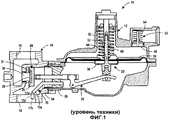
На фиг.10 показан традиционный газовый регулятор 10. Регулятор 10 в целом содержит исполнительный механизм 12 и клапан 14 регулятора. Клапан регулятора ограничивает впускное отверстие 16 для приема газа, например, от газораспределительной системы и выпускное отверстие 18 для подачи газа к установке конечного пользователя, например, заводу, ресторану, жилому зданию и т.п., имеющей один или более потребителей. Клапан 14 регулятора дополнительно включает клапанное окно 36, расположенное между впускным и выпускным отверстием. Газ при перемещении от впускного отверстия 16 к выпускному отверстию 18 клапана 14 регулятора проходит через клапанное окно 36.10 shows a
Исполнительный механизм 12 присоединен к клапану 14 регулятора для обеспечения соответствия давления в выпускном отверстии 18 клапана 14 регулятора, то есть давления на выпуске, требуемому давлению на выпуске или давлению в системе регулирования. Поэтому исполнительный механизм 12 находится в проточном сообщении с клапаном 14 регулятора через горловину 34 клапана и горловину 20 исполнительного механизма. Исполнительный механизм 12 включает узел 22 регулирования для регулирования давления на выпуске клапана 14 регулятора на основе воспринимаемого давления на выпуске. Более конкретно, узел 22 регулирования включает несущую пластину 19 мембраны, мембрану 24, поршень 32 и регулирующий рычаг 26, имеющий клапанный диск 28. Клапанный диск 28 включает в целом цилиндрический корпус 25 и уплотнительный вкладыш 29, прикрепленный к корпусу 25. Мембрана 24 воспринимает давление на выпуске клапана 14 регулятора и в зависимости от него перемещает клапанный диск 28 для открытия и закрытия клапана 14 регулятора. Узел 22 регулирования дополнительно включает регулирующую пружину 30, находящуюся в контакте с верхней частью узла 22 регулирования для компенсации воспринимаемого мембраной 24 давления на выпуске. Соответственно требуемое давление на выпуске, которое может также называться давлением в системе регулирования, устанавливается путем выбора регулирующей пружины 30.An
Мембрана 24 функционально соединена с регулирующим рычагом 26, а также с клапанным диском 28 с помощью поршня 32 и регулирует открытие клапана 14 регулятора на основе воспринимаемого давления на выпуске. Например, при работе конечного потребителя, например, печи, появляется расход в газораспределительной системе после регулятора 10, при этом уменьшается давление на выпуске. Соответственно мембрана воспринимает это уменьшенное давление на выпуске. Это обеспечивает растяжение регулирующей пружины 30, а также перемещение поршня 32 и правой части регулирующего рычага 26 вниз в соответствии с ориентацией, показанной на фиг.1. Это смещение регулирующего рычага 26 перемещает клапанный диск 28 от клапанного окна 36 для открытия клапана 14 регулятора, тем самым увеличивая расход на выпуске для удовлетворения увеличенного потребления и увеличивая давления на выпуске до давления в системе регулирования. При этом к потребителю может подводиться газ через клапанное окно 36 и через выпускное отверстие 18 клапана 14 регулятора.The
В традиционном регуляторе 10 регулирующая пружина 30 по своей природе создает меньшее усилие по мере растяжения к несжатому состоянию при смещении регулирующего рычага 26 для открытия клапанного окна 36. Кроме того, по мере растяжения регулирующей пружины 30 мембрана 24 деформируется, что приводит к увеличению площади мембраны 24. Уменьшенное усилие регулирующей пружины и увеличенная площадь мембраны 24 в этом случае вместе являются причиной того, что при работе регулятора усилие, обеспечиваемое регулирующей пружиной 30, становится недостаточным для компенсации усилия, создаваемого мембраной 24, что приводит к уменьшению давления на выпуске в системе регулирования по сравнению с первоначально установленным конечным потребителем. Это явление известно как "провал". При возникновении "провала" давление на выпуске уменьшается ниже установленного давления в системе регулирования, и регулятор 10 работает некорректно. "Провал" является одним из примеров отрицательных воздействий динамических давлений, которые могут возникать в регуляторе 10.In the
Для противодействия этим воздействиям некоторые традиционные регуляторы 10 включают трубку 15 для измерения давления. Измерительная трубка 15 может включать прямую измерительную трубку 15а, как показано сплошной линией на фиг.1, или может включать изогнутую измерительную трубку 15b, как показано пунктирной линией. Обе измерительные трубки 15а, 15b включают удлиненную цилиндрическую трубку с открытым измерительным концом 17а, 17b. Открытый конец 17а, 17b выполнен с возможностью измерения давления газа в выпускном отверстии клапана 14 регулятора, а трубки 15а, 15b выполнены с возможностью передачи измеренного давления к мембране 24. Таким образом, измерительные трубки 15а, 15b обеспечивают более точное определение давления в выпускном отверстии 18 клапана 14 регулятора, чем давление, воспринимаемое мембраной 24 в противном случае. Работа без измерительных трубок 15а, 15b часто приводит к давлению большему, чем давление на выпуске, воспринимаемое мембраной 24, из-за эффектов динамического давления.To counter these influences, some
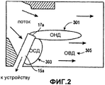
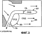
Например, как показано на фиг.2 и 3, по мере прохождения потока газа из клапанного окна 36 и расширения, газ проходит дальше и попадает в измерительную трубку 15а, 15b. При этом создаются три области давления. К этим трем областям относятся область 301 низкого давления (ОНД), область 303 среднего давления (ОСД) и область 305 высокого давления (ОВД).For example, as shown in FIGS. 2 and 3, as the gas flows from the
Традиционные измерительные трубки 15а, 15b, показанные на фиг.2 и 3, имеют открытые концы 17а, 17b, как указано выше. Открытые концы 17а, 17b лишь передают давления из ОНД 301 к мембране 24 исполнительного механизма 12, показанной на фиг.1. Давление в ОНД 301 уменьшается пропорционально расходу в измерительных трубках 15а, 15b. По мере увеличения расхода давление в ОНД 301 начинает значительно отклоняться от фактического давления на выпуске, тем самым приводя к все более неточному определению давления, передаваемого к мембране 24 исполнительного механизма 12. Это может привести к восприятию мембраной 24 давления, которое ниже, чем фактическое давление на выпуске, что может быть нежелательным.
Как показано на фиг.1, узел 22 регулирования традиционного регулятора 19 дополнительно служит в качестве предохранительного клапана. Более конкретно, узел 22 регулирования также включает предохранительную пружину 40 и перепускной клапан 42. Мембрана 24 включает отверстие 44 в ее центральной части, а поршень 32 включает уплотнительную манжету 38. Предохранительная пружина 40 расположена между поршнем 32 и мембраной 24 для смещения мембраны 24 к уплотнительной манжете 38 и закрытия отверстия 44 при нормальной работе. При возникновении неисправности, например выходе из строя регулирующего рычага 26, узел 22 регулирования больше не связан непосредственно с клапанным диском 28, и поток на впуске перемещает клапанный диск 28 в крайнее открытое положение. Это приводит к попаданию большого количества газа в исполнительный механизм 12. Таким образом, по мере наполнения исполнительного механизма 12 газом давление на мембрану 24 возрастает, что вызывает перемещение мембраны 24 от уплотнительной манжеты 38 и тем самым открытие отверстия 44. Вследствие этого газ проходит через отверстие 33 в мембране к перепускному клапану 42. Перепускной клапан 42 включает пробку 46 клапана и перепускную пружину 54, смещающую клапанную пробку 46 в закрытое положение, как показано на фиг.1. При достижении давлением в исполнительном механизме 42 и смежном перепускном клапане 42 заданного порога давления клапанная пробка 46 смещается вверх, сжимая перепускную пружину 54, и открывается, выпуская тем самым газ в атмосферу и уменьшая давление в регуляторе 10. Измерительная трубка 15 также может способствовать обеспечению регулятором 10 предохранительной функцией путем подачи сигнала, представляющего фактическое давление на выпуске, к мембране 24 исполнительного механизма 12. Однако, как указано выше, давление, измеренное традиционной измерительной трубкой 15, например, при больших расходах, может быть неточным.As shown in FIG. 1, the
Раскрытие изобретенияDisclosure of invention
В настоящем изобретении предложен регулятор, содержащий клапан регулятора и исполнительный механизм. Исполнительный механизм присоединен к клапану регулятора и содержит регулирующий элемент для регулирования потока текучей среды через клапан регулятора. Исполнительный механизм дополнительно содержит измерительную трубку, имеющую функцию усреднения давления, для измерения фактического давления в выпускном отверстии клапана регулятора. Усредненное фактическое давление затем передается в исполнительный механизм для настройки положения регулирующего элемента.The present invention provides a regulator comprising a regulator valve and an actuator. An actuator is connected to the valve of the regulator and contains a regulating element for regulating the flow of fluid through the valve of the regulator. The actuator further comprises a measuring tube having a pressure averaging function for measuring the actual pressure in the outlet of the regulator valve. The averaged actual pressure is then transmitted to the actuator to adjust the position of the control element.
В одном примере осуществления измерительная трубка, имеющая функцию усреднения давления, включает открытый измерительный конец и удлиненную прорезь. Удлиненная прорезь может включать прямолинейную прорезь, волнообразную прорезь, прорезь, имеющую переменную толщину, или прорезь любой другой формы.In one embodiment, the measuring tube having a pressure averaging function includes an open measuring end and an elongated slot. An elongated slot may include a straight slot, a wave-shaped slot, a slot having a variable thickness, or a slot of any other shape.
В других примерах осуществления размер, форма и другие факторы или характеристики прорези и/или измерительной трубки могут быть изменены под конкретное применение определенного устройства для регулирования текучей среды.In other embodiments, the size, shape, and other factors or characteristics of the slot and / or measuring tube may be modified to suit the particular application of a particular fluid control device.
Краткое описание чертежейBrief Description of the Drawings
Фиг.1 представляет собой вид бокового поперечного разреза традиционного регулятора.Figure 1 is a side cross-sectional view of a conventional adjuster.
Фиг.2 представляет собой схематичный вид областей давления, образованных около одной измерительной трубки, выполненной с возможностью использования с регулятором.Figure 2 is a schematic view of pressure areas formed near one measuring tube, configured to be used with a regulator.
Фиг.3 представляет собой схематичный вид областей давления, образованных около другой измерительной трубки, выполненной с возможностью использования с регулятором.Figure 3 is a schematic view of pressure regions formed near another measuring tube configured to be used with a regulator.
Фиг.4 представляет собой вид бокового поперечного разреза регулятора, включающего измерительную трубку, причем регулятор и измерительная трубка выполнены в соответствии с одним примером осуществления настоящего изобретения.4 is a side cross-sectional view of a regulator including a measuring tube, wherein the regulator and the measuring tube are made in accordance with one embodiment of the present invention.
Фиг.5 представляет собой вид в аксонометрии одного примера осуществления измерительной части измерительной трубки, имеющей функцию усреднения давления, выполненной в соответствии с принципами настоящего изобретения.FIG. 5 is a perspective view of one embodiment of a measuring portion of a measuring tube having a pressure averaging function made in accordance with the principles of the present invention.
Фиг.6А-6D представляют собой виды в аксонометрии различных альтернативных примеров осуществления измерительных частей измерительных трубок, имеющих функцию усреднения давления, выполненных в соответствии с принципами настоящего изобретения.6A-6D are perspective views of various alternative embodiments of measuring parts of measuring tubes having a pressure averaging function, made in accordance with the principles of the present invention.
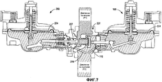
Фиг.7 представляет собой вид бокового поперечного разреза другого альтернативного примера осуществления настоящего изобретения, включающего регулятор и устройство для контроля, которые содержат измерительные трубки, имеющие функцию усреднения давления, выполненные соответствии с принципами настоящего изобретения.Fig. 7 is a side cross-sectional view of another alternative embodiment of the present invention, including a regulator and a monitoring device, which comprise measuring tubes having a pressure averaging function in accordance with the principles of the present invention.
Осуществление изобретенияThe implementation of the invention
На фиг.4 показан газовый регулятор 100, включающий измерительную трубку 115, причем регулятор 100 и измерительная трубка 115 выполнены в соответствии с одним примером осуществления настоящего изобретения. Регулятор 100 газа в целом содержит исполнительный механизм 102 и клапан 104 регулятора. Клапан 104 регулятора включает впускное отверстие 106 для приема газа, например, от газораспределительной системы, и выпускное отверстие 108 для подачи газа к установке, имеющей один или более потребителей. Исполнительный механизм 102 присоединен к клапану 104 регулятора и включает узел 122 регулирования, имеющий регулирующий элемент 127. В первом нормальном режиме работы узел 122 регулирования воспринимает давление в выпускном отверстии 108 клапана 104 регулятора, то есть давление на выпуске, и регулирует положение регулирующего элемента 127 таким образом, что давление на выпуске приблизительно равняется заданному давлению в системе регулирования. Дополнительно при возникновении неисправности в системе регулятор 100 обеспечивает функцию предохранения, которая в целом подобна функции предохранения, описанной выше со ссылкой на регулятор 10, показанный на фиг.1.FIG. 4 shows a
Клапан 104 регулятора ограничивает проходное отверстие 110 и горловину 112 клапана. Проходное отверстие 110 расположено между впускным отверстием 106 и выпускным отверстием 108. Клапанное окно 136 расположено в проходном отверстии 110 и ограничивает канал 148, имеющий впускное отверстие 150 и выпускное отверстие 152. Газ при перемещении от впускного отверстия 106 к выпускному отверстию 108 клапана 104 регулятора проходит через канал 148 клапанного окна 136. Клапанное окно 136 выполнено с возможностью извлечения из клапана 104 регулятора, так что оно может быть заменено другим клапанным окном, имеющим канал другого диаметра или конструкцию, обеспечивающую рабочую характеристику или характеристику расхода клапана 104 регулятора для конкретного применения. В описанном примере осуществления горловина 112 клапана ограничивает отверстие 114, расположенное по оси, в целом перпендикулярной оси впускного отверстия 106 и выпускного отверстия 108 клапана 104 регулятора.The valve 104 of the regulator limits the bore 110 and the neck 112 of the valve. An orifice 110 is located between the inlet 106 and the outlet 108. A valve port 136 is located in the orifice 110 and defines a passage 148 having an inlet 150 and an outlet 152. Gas moves from the inlet 106 to the outlet 108 of the regulator valve 104 through the channel 148 of the valve window 136. The valve window 136 is configured to be removed from the valve 104 of the regulator, so that it can be replaced by another valve window having a channel of a different diameter or design, about espechivayuschuyu operating characteristic or valve flow characteristic 104 for a particular application controller. In the described embodiment, the neck of the valve 112 defines an opening 114 located on an axis generally perpendicular to the axis of the inlet 106 and the outlet 108 of the regulator valve 104.
Исполнительный механизм 102 включает корпус 116 и узел 122 регулирования, как указано выше. Корпус 116 включает верхнюю часть 116а корпуса и нижнюю часть 116b корпуса, соединенные друг с другом, например, множеством крепежных средств. Нижняя часть 116b корпуса ограничивает регулирующую полость 118 и горловину 120 исполнительного механизма. Горловина 120 исполнительного механизма присоединена к горловине 112 клапана 104 регулятора для обеспечения проточного сообщения между исполнительным механизмом 102 и горловиной 104 регулятора. В описанном примере осуществления регулятор 100 включает хомут 111, соединяющий горловины 112, 120 друг с другом. Верхняя часть 116а корпуса ограничивает предохранительную полость 134 и выпускное окно 156. Верхняя часть 116а корпуса дополнительно ограничивает выступающую часть 158 для размещения части узла 122 регулирования, как описано ниже.The actuator 102 includes a housing 116 and a control unit 122, as described above. The housing 116 includes an upper housing portion 116a and a lower housing portion 116b connected to each other, for example, by a plurality of fastening means. The lower part 116b of the housing limits the control cavity 118 and the neck 120 of the actuator. The neck 120 of the actuator is connected to the neck 112 of the valve 104 of the regulator to provide flow communication between the actuator 102 and the neck 104 of the regulator. In the described embodiment, the
Узел 122 регулирования включает узел 121 мембраны, узел 123 диска и перепускной клапан 142. Узел 121 мембраны включает несущую пластину 109 мембраны, мембрану 124, поршень 132, регулирующую пружину 130, предохранительную пружину 140, объединенное гнездо 164 пружины, гнездо 166 предохранительной пружины, гнездо 160 регулирующей пружины и направляющую 159 поршня.The regulation unit 122 includes a membrane unit 121, a disk unit 123, and a bypass valve 142. The membrane unit 121 includes a membrane carrier plate 109, a membrane 124, a piston 132, a control spring 130, a safety spring 140, an integrated spring socket 164, a safety spring socket 166, a socket 160 control springs and piston guide 159.
Более конкретно, мембрана 124 включает мембрану в форме диска, ограничивающую отверстие 144 в ее центральной части. Мембрана 124 выполнена из гибкого, по существу воздухонепроницаемого материала, и ее периферия герметично зафиксирована между верхней и нижней частями 116а, 116b корпуса 116. Таким образом, мембрана 124 отделяет предохранительную полость 134 от регулирующей полости 118.More specifically, the membrane 124 includes a disk-shaped membrane defining a hole 144 in its central part. The membrane 124 is made of a flexible, essentially airtight material, and its periphery is hermetically fixed between the upper and lower parts 116a, 116b of the housing 116. Thus, the membrane 124 separates the safety cavity 134 from the control cavity 118.
Объединенное гнездо 164 пружины расположено на мембране 124 и ограничивает отверстие 170, расположенное концентрически с отверстием 144 в мембране 124. Как показано на фиг.4, объединенное гнездо 164 пружины поддерживает регулирующую пружину 130 и предохранительную пружину 140.The combined spring receptacle 164 is located on the membrane 124 and delimits an opening 170 concentrically located with the opening 144 in the membrane 124. As shown in FIG. 4, the integrated spring receptacle 164 supports the control spring 130 and the safety spring 140.
Поршень 132 в описанном примере осуществления включает в целом удлиненный элемент в форме штока, имеющий часть 138 уплотнительной манжеты, вилку 172, часть 174 с резьбой и направляющую часть 175. Часть 138 уплотнительной манжеты вогнутая и в целом имеет форму диска, а также проходит вокруг средней части поршня 132 и расположена непосредственно под мембраной 124. Вилка 172 включает полость, выполненную с возможностью размещения соединителя 135, который соединяет часть узла 123 диска для обеспечения соединения узла 121 мембраны с узлом 123 диска, как описано ниже.The piston 132 in the described embodiment includes a generally elongated rod-shaped member having a sealing lip portion 138, a plug 172, a threaded portion 174, and a guide portion 175. The sealing lip portion 138 is concave and generally has a disk shape and also extends around the middle parts of the piston 132 and is located directly below the membrane 124. The plug 172 includes a cavity configured to accommodate a connector 135 that connects a portion of the disk assembly 123 to allow the membrane assembly 121 to be connected to the disk assembly 123, as described below same.
Направляющая часть 175 и часть 174 с резьбой поршня 132 расположены в отверстиях 144, 170 в мембране 124 и в объединенном гнезде 164 пружины, соответственно. Направляющая часть 175 поршня 132 расположена с возможностью скольжения в полости в направляющей 159 поршня, которая обеспечивает осевое выравнивание поршня 132 относительно остальной части узла 122 регулирования. Предохранительная пружина 140, гнездо 166 предохранительной пружины и гайка 176 расположены на части 174 с резьбой поршня 132. Гайка удерживает предохранительную пружину 140 между объединенным гнездом 164 пружины и гнездом 166 предохранительной пружины. Регулирующая пружина 130 расположена на объединенном гнезде 164 пружины, как указано, внутри выступающей части 158 верхней части 116а корпуса. Гнездо 160 регулирующей пружины навинчено на выступающую часть 158 и сжимает регулирующую пружину 130 с объединенным гнездом 164 пружины. В описанном примере осуществления регулирующая пружина 130 и предохранительная пружина 140 включают винтовые пружины сжатия. Соответственно регулирующая пружина 130 посажена напротив верхней части 116а корпуса и создает усилие, направленное вниз к объединенному гнезду 164 пружины и мембране 124. Предохранительная пружина 140 посажена напротив объедененного гнезда 164 пружины и создает усилие, направленное вверх к гнезду 166 предохранительной пружины, которая в свою очередь прикладывается к поршню 132. В описанном примере осуществления усилие, создаваемое регулирующей пружиной 130, может регулироваться путем регулировки положения гнезда 160 регулирующей пружины в выступающей части 158, и, следовательно, давление в системе регулирование регулятора 100 также может регулироваться.A guide portion 175 and a threaded portion 174 of the piston 132 are located in holes 144, 170 in the membrane 124 and in the associated spring seat 164, respectively. The guide portion 175 of the piston 132 is slidably disposed in a cavity in the piston guide 159, which provides axial alignment of the piston 132 with respect to the rest of the control unit 122. The safety spring 140, the safety spring socket 166 and the nut 176 are located on the piston threaded portion 174. The nut holds the safety spring 140 between the combined spring socket 164 and the safety spring socket 166. The control spring 130 is located on the combined spring socket 164, as indicated, inside the protruding portion 158 of the upper housing portion 116a. The control spring receptacle 160 is screwed onto the protruding portion 158 and compresses the control spring 130 with the integrated spring receptacle 164. In the described embodiment, the control spring 130 and the safety spring 140 include compression coil springs. Accordingly, the control spring 130 is seated opposite the upper housing portion 116a and generates a downward force towards the combined spring socket 164 and the membrane 124. The safety spring 140 is seated opposite the joined spring socket 164 and generates a force directed upward to the safety spring socket 166, which in turn applied to the piston 132. In the described embodiment, the force exerted by the control spring 130 can be adjusted by adjusting the position of the control spring receptacle 160 in the protrusions part 158, and therefore the pressure in the system, the regulation of the
Регулирующая пружина 130 сжимается под действием давления в регулирующей полости 118, воспринимаемого мембраной 124. Соответственно усилие, создаваемое регулирующей пружиной 130, устанавливает требуемое давление на выпуске или давление в системе регулирования регулятора 100. Узел 121 мембраны функционально соединен с узлом 123 диска, как указано выше, через часть 172 вилки поршня 132 и соединитель 135.The control spring 130 is compressed by the pressure in the control cavity 118 perceived by the membrane 124. Accordingly, the force generated by the control spring 130 sets the desired outlet pressure or pressure in the control system of the
Более конкретно, узел 123 диска включает регулирующий рычаг 126 и направляющую 162 стержня. Регулирующий рычаг 126 включает стержень 178, плечо 180 и регулирующий элемент 127. Регулирующий элемент 127 в описанном примере осуществления включает клапанный диск 128. Дополнительно в описанном примере осуществления клапанный диск 128 включает уплотнительный диск 129 для уплотнения клапанного окна 136, как показано на фиг.4. Уплотнительный диск 129 может быть прикреплен к остальной части клапанного диска 128 с помощью, например, клейкого вещества или других средств. Уплотнительный диск 129 может быть выполнен из того же материала, что и остальная часть клапанного диска 128, или другого материала. Например, в одном примере осуществления уплотнительный диск 129 может включать полимерный уплотнительный диск 129.More specifically, the disk assembly 123 includes a control lever 126 and a rod guide 162. The control lever 126 includes a shaft 178, a shoulder 180 and a control element 127. The control element 127 in the described embodiment includes a valve disc 128. Additionally, in the described embodiment, the valve disc 128 includes a sealing disk 129 for sealing the valve window 136, as shown in FIG. 4 . The sealing disc 129 may be attached to the rest of the valve disc 128 using, for example, an adhesive or other means. The sealing disc 129 may be made of the same material as the rest of the valve disc 128, or another material. For example, in one embodiment, the sealing disc 129 may include a polymer sealing disc 129.
Стержень 178, плечо 180 и клапанный диск 128 выполнены отдельно и собраны для образования регулирующего рычага 126. Более конкретно, стержень 178 представляет собой в целом прямой шток, имеющий выступ 178а и углубление 178b, которое в описанном примере осуществления в целом прямоугольное. Плечо 180 представляет собой слегка изогнутый шток и включает конец 180а с точкой опоры и свободный конец 180b. Конец 180а с точкой опоры включает отверстие 184, в котором размещен палец 186, установленный на нижней части 116b корпуса. Конец 180а с точкой опоры также включает кулак 187, имеющий эллиптическое поперечное сечение и расположенный в углублении 178b стержня 178. Свободный конец 180b размещен между верхней частью 135а и пальцем 135b соединителя 135, который прикреплен к вилке 172 поршня 132. Таким образом, соединитель 135 функционально соединяет узел 123 диска с узлом 121 мембраны.The shaft 178, the shoulder 180, and the valve disc 128 are formed separately and assembled to form the control lever 126. More specifically, the shaft 178 is a generally straight rod having a protrusion 178a and a recess 178b, which is generally rectangular in the described embodiment. The shoulder 180 is a slightly curved rod and includes an end 180a with a fulcrum and a free end 180b. The fulcrum end 180a includes an opening 184 in which a pin 186 is mounted, mounted on a lower housing portion 116b. The fulcrum end 180a also includes a fist 187 having an elliptical cross section and located in the recess 178b of the shaft 178. The free end 180b is located between the upper part 135a and the pin 135b of the connector 135, which is attached to the plug 172 of the piston 132. Thus, the connector 135 connects the disk assembly 123 to the membrane assembly 121.
Направляющая 162 стержня включает в целом цилиндрическую внешнюю часть 162а, в целом цилиндрическую внутреннюю часть 162b и множество перемычек 162с, соединяющих внутреннюю и внешнюю части 162b, 162а. Внешняя часть 162а направляющей 162 стержня выполнена с возможностью размещения в горловинах 112, 120 клапана 104 регулятора 104 и нижней части 116b корпуса, соответственно. Внутренняя часть 162b выполнена с возможностью удерживания стержня 178 регулирующего рычага 126 с возможностью скольжения. Таким образом, направляющая 162 стержня служит для обеспечения выравнивания клапана 104 регулятора, корпуса 116 исполнительного механизма, узла 122 регулирования и, более конкретно, стержня 178 регулировочного рычага 126 узла 122 регулирования.The rod guide 162 includes a generally cylindrical outer part 162a, a generally cylindrical inner part 162b, and a plurality of jumpers 162c connecting the inner and outer parts 162b, 162a. The outer portion 162a of the rod guide 162 is arranged to fit in the necks 112, 120 of the valve 104 of the regulator 104 and the lower housing portion 116b, respectively. The inner part 162b is arranged to hold the shaft 178 of the adjusting lever 126 with the possibility of sliding. Thus, the rod guide 162 serves to align the valve 104 of the regulator, the actuator housing 116, the regulation unit 122, and more specifically, the adjustment lever rod 178 126 of the regulation unit 122.
На фиг.4 показан регулирующий элемент 127 в закрытом положении, в котором клапанный диск 128 герметично входит в контакт с выпускным отверстием 152 клапанного окна 136. При этом газ не проходит через клапанное окно 136 и клапан 104 регулятора закрыт. Такое положение обеспечивается, когда давление на выпуске, которое соответствует давлению в регулирующей полости 118 корпуса 116 и воспринимается мембраной 124, превышает усилие, создаваемое регулирующей пружиной 130. Соответственно давление на выпуске перемещает мембрану 124 и поршень 132 в закрытое положение.Figure 4 shows the control element 127 in the closed position, in which the valve disk 128 is tightly in contact with the outlet 152 of the valve window 136. In this case, the gas does not pass through the valve window 136 and the valve 104 of the regulator is closed. This situation is ensured when the pressure at the outlet, which corresponds to the pressure in the control cavity 118 of the housing 116 and is perceived by the membrane 124, exceeds the force exerted by the control spring 130. Accordingly, the pressure at the outlet moves the membrane 124 and the piston 132 to the closed position.
Однако в случае появления рабочего расхода в газораспределительной системе, например, начала работы потребителя, например, печи, плиты и т.п., данный потребитель потребляет газ из регулирующей полости 118 регулятора 100, таким образом уменьшая давление, воспринимаемое мембраной 124. По мере уменьшения давления, воспринимаемого мембраной 124, возникает неравенство усилия регулирующей пружины и усилия, создаваемого давлением на выпуске и прикладываемого к мембране 124, так что регулирующая пружина 130 растягивается и смещает мембрану 124 и поршень 132 вниз относительно корпуса 116. Это вызывает поворот плеча 180 по часовой стрелке вокруг пальца 186, который в свою очередь поворачивает кулак 187 относительно углубления 178b в стержне 178. При этом стержень 178 и клапанный диск 128 перемещаются от выпускного отверстия 152 клапанного окна 136, открывая клапан 104 регулятора.However, in the event of a working flow rate in the gas distribution system, for example, when the consumer starts working, for example, a stove, stove, etc., this consumer consumes gas from the control cavity 118 of the
При этом газораспределительная система подает газ к последующему потребителю через клапан 104 регулятора при давлении в системе регулирования, установленном регулирующей пружиной 130. Дополнительно узел 121 мембраны продолжает воспринимать давление на выпуске клапана 104 регулятора. Пока давление на выпуске остается примерно равным давлению в системе регулирования, узел 122 регулирования поддерживает клапанный диск 128 в одном положении. Однако, если расход на выпуске, то есть потребление уменьшается, тем самым увеличивая давление на выпуске сверхдавления в системе регулирования, установленного регулирующей пружиной 130, мембрана 124 воспринимает увеличенное давление на выпуске и перемещается вверх, сжимая регулирующую пружину 130. В другом случае, если расход на выпуске, то есть потребление увеличивается, тем самым уменьшая давление на выпуске ниже давления в системе регулирования, мембрана 124 воспринимает уменьшенное давление на выпуске, и пружина 130 смещает мембрану 124 и поршень 132 вниз, открывая клапан 104 регулятора. Таким образом, узел 122 регулирования реагирует на небольшие отклонения от давления на выпуске или давления в системе регулирования и регулирует положение клапанного диска 128.In this case, the gas distribution system supplies gas to the subsequent consumer through the regulator valve 104 at a pressure in the control system set by the regulating spring 130. Additionally, the membrane assembly 121 continues to absorb pressure at the outlet of the regulator valve 104. As long as the outlet pressure remains approximately equal to the pressure in the control system, the control unit 122 keeps the valve disc 128 in one position. However, if the discharge flow rate, i.e. consumption, decreases, thereby increasing the pressure at the overpressure outlet in the control system installed by the control spring 130, the membrane 124 senses the increased discharge pressure and moves upward, compressing the control spring 130. Otherwise, if the flow rate at the outlet, that is, consumption increases, thereby reducing the pressure at the outlet below the pressure in the control system, the membrane 124 senses a reduced pressure at the outlet, and the spring 130 biases the membrane 124 and p rshen 132 downward, opening the regulator valve 104. Thus, the control unit 122 responds to small deviations from the outlet pressure or the pressure in the control system and adjusts the position of the valve disc 128.
По мере растяжения регулирующей пружины 130, смещения клапанного диска 127 и открытия клапанного окна 136 усилие, создаваемое пружиной, и площадь мембраны 124 уменьшаются. Как описано выше со ссылкой на традиционный регулятор 10, показанный на фиг.1, такое уменьшение усилия пружины и уменьшение площади мембраны может уменьшить давление на выпуске, необходимое для уравновешивания мембраны 124 и воспринимаемое ей. Таким образом, это приводит к уменьшению давления на выпуске ниже давления в системе регулирования, и по мере увеличения расхода величина отклонения пропорционально увеличивается. Как указано выше, это явление известно как "провал". Одно традиционное решение для борьбы с "провалом" заключается в установке в регуляторе одной из измерительных трубок 15а, 15b, описанных выше со ссылкой на фиг.1. Однако, как описано, традиционные измерительные трубки 15а, 15b имеют недостатки, заключающиеся в том, что данные трубки не всегда точно определяют давление из-за динамических явлений потока текучей среды, проходящей через клапан регулятора, и, в частности, наличия изменяющихся давлений в ОНД 301, смежной с измерительными концами 17а, 17b.As the control spring 130 stretches, the valve disc 127 biases, and the valve window 136 opens, the force generated by the spring and the area of the membrane 124 decrease. As described above with reference to the
Соответственно регулятор, показанный на фиг.4, имеет измерительную трубку 115, выполненную с возможностью усреднения давления, измеренного в выпускном отверстии 108 клапана 104 регулятора. Такое усреднение позволяет измерительной трубке 115 передавать более точный сигнал давления в регулирующую полость 118 исполнительного механизма и, в частности, к мембране 124. Измерительная трубка 115, показанная на фиг.4, в целом похожа на измерительную трубку 15а, показанную на фиг.1, тем, что включает цилиндрическую трубку, имеющую измерительную часть 117 и крепежную часть 119, причем измерительная часть 117 включает открытый измерительный конец 117а. Крепежная часть 119 расположена под углом относительно измерительной части 117. Дополнительно измерительная часть 117 измерительной трубки 115 в примере осуществления, показанном на фиг.4, включает удлиненную прорезь 131, которая лучше показана на фиг.5. Прорезь 131 в примере осуществления, показанном на фиг.5, включает прямолинейную прорезь, проходящую от измерительного конца 117а измерительной части 117 по существу к крепежной части 119.Accordingly, the regulator shown in FIG. 4 has a measuring
Как показано на фиг.4, крепежная часть 119 в описанном примере осуществления расположена в направляющей 162 стержня узла 123 диска исполнительного механизма 102. Более конкретно, крепежная часть 119 установлена между парой радиальных перемычек 162 с направляющей 162 стержня. В одном примере осуществления крепежная часть 119 может быть закреплена между радиальными перемычкам 162 с направляющей 162 стержня с помощью посадки с натягом, клейкого вещества, шлицевого соединения или в целом других средств. При этом измерительная часть 117 измерительной трубки 115 расположена вблизи выпускного отверстия 108 клапана 104 регулятора. Таким образом, как показано на фиг.4, прорезь 131 в измерительной части 117 измерительной трубки 115 направлена от клапанного окна 136, например, в направлении потока от клапанного окна 136. Другими словами, прорезь 131 находится в сообщении, например, с областью 303 среднего давления (ОСД), показанной на фиг.2. Дополнительно измерительный конец 117а находится в сообщении, например, с областью 301 низкого давления (ОНД), показанной на фиг.2. Поэтому измерительная трубка 115, имеющая функцию усреднения давления, может не только измерять давления в ОНД 301 с помощью измерительного конца 117а, но также может производить измерения давления в ОСД 303 во множестве точек вдоль прорези 131. Например, для объяснения прорезь 131 ограничивает множество точек 131а измерения давления вдоль измерительной трубки 115, имеющей функцию усреднения давления, как показано на фиг.5. Несмотря на то, что на фиг.5 показаны лишь пять таких точек 131а измерения давления, специалисту в данной области техники понятно, что количество точек 131а измерения давления вдоль прорези 131 в сущности может быть бесконечным.As shown in FIG. 4, the mounting portion 119 in the described embodiment is located in the rod guide 162 of the actuator disk assembly 123 123. More specifically, the fixing portion 119 is mounted between a pair of radial bridges 162 with the rod guide 162. In one embodiment, the fastener portion 119 may be secured between the radial bridges 162 with the rod guide 162 by interference fit, adhesive, spline connection, or other means in general. In this case, the measuring
Таким образом, измерительная трубка 115, имеющая функцию усреднения давления, в настоящем примере осуществления настоящего изобретения передает давление из ОНД 301 и ОСД 303, показанных на фиг.2, тем самым обеспечивая среднее давление в выпускном отверстии 108 исполнительного механизма 102. Это усреднение компенсирует уменьшение давления в ОНД 301, которое возникает из-за увеличенного расхода через клапан 104 регулятора. Поэтому давление, переданное к исполнительному механизму 102 измерительной трубкой 115, имеющей функцию усреднения давления, более точно соответствует действительному давлению в выпускном отверстии. Еще одним преимуществом измерительной трубки 115, имеющей функцию усреднения давления, является то, что по мере дальнейшего увеличения расхода через клапан 104 регулятора точность измерения давления измерительной трубкой 115, имеющей функцию усреднения давления, по сравнению с традиционными измерительными трубками 15а, 15b возрастает все больше.Thus, the measuring
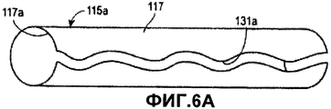
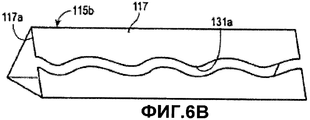
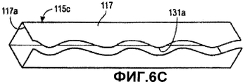
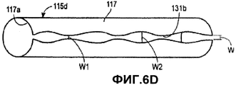
Несмотря на то, что описанная измерительная трубка 115, имеющая функцию усреднения давления, включает цилиндрическую измерительную трубку 115, имеющую в целом прямолинейную прорезь 131, например, как показано на фиг.5, альтернативные примеры осуществления могут включать альтернативные геометрические формы. Например, на фиг.6А-6D показаны альтернативные измерительные трубки 115a-115d, имеющие функцию усреднения давления, выполненные в соответствии с принципами настоящего изобретения. Каждая из измерительных трубок 115а-115c, показанных на фиг.6А-6C, включает волнообразные прорези 131а, проходящие от соответствующих измерительных концов 117а измерительных частей 117. Напротив, измерительная трубка 115d, показанная на фиг.6D, включает прорезь 131b, имеющую переменную ширину W. В описанном примере осуществления ширина W прорези 131b, показанной на фиг.6, изменяется от минимальной величины W1 до максимальной величины W2 таким образом, что зависимость ширины W от длины измерительной трубки 115d может быть похожа, например, на синусоидальную кривую.Although the described measuring
Настоящее изобретение не ограничивается только цилиндрическими измерительными трубками. Например, измерительная трубка 115b, показанная на фиг.6B, включает в целом треугольное поперечное сечение. Кроме того, измерительная трубка 115c, показанная на фиг.6C, включает в целом прямоугольное и по меньшей мере в одном примере осуществления квадратное поперечное сечение. Настоящее изобретение может включать измерительную трубку в целом любого поперечного сечения.The present invention is not limited to cylindrical measuring tubes. For example, the measuring
Соответственно следует понимать, что настоящее изобретение не ограничивается описанными здесь примерами осуществления измерительных трубок 115, имеющих функцию усреднения давления, и множество альтернативных форм измерительных трубок и прорезей могут быть выполнены с возможностью использования принципов настоящего изобретения и поэтому считаются соответствующими объему настоящего изобретения. В другом альтернативном примере осуществления измерительная трубка 115, имеющая функцию усреднения давления, может не включать прорезь совсем, а включать множество отдельных отверстий, расположенных на расстоянии друг от друга вдоль измерительной части 117 измерительной трубки 115 в местах, в которых в другом случае размещалась бы прорезь 131.Accordingly, it should be understood that the present invention is not limited to the exemplary embodiment of the measuring
Более того, понятно, что конкретная форма измерительной трубки 115, имеющей функцию усреднения давления, выполненной в соответствии с настоящим изобретением и имеющей определенную форму поперечного сечения, форму и ширину прорези 131, может быть изменена под любые требования к регулятору. Например, может быть целесообразным выполнение или выбор измерительной трубки 115, имеющей конкретное поперечное сечение и форму прорези и/или размер для оптимального функционирования с любым набором параметром регулятора, например, пропускной способностью, давлением в выпускном отверстии, размером клапана регулятора, размером клапанного окна и т.д.Moreover, it is understood that the specific shape of the measuring
Кроме того, несмотря на то, что описанная здесь измерительная трубка 115, имеющая функцию усреднения давления, включает прорезь 131, расположенную только в измерительной части 117, альтернативные примеры осуществления могут включать прорезь 131, также проходящую через крепежную часть 119. Дополнительно, несмотря на то, что описанная измерительная трубка 115, имеющая функцию усреднения давления, похожа на прямую измерительную трубку 115, показанную на фиг.2, измерительная трубка 115 настоящего изобретения может, например, также быть выполнена как изогнутая измерительная трубка, похожая на трубку, показанную на фиг.3. При этом изогнутая измерительная трубка, выполненная в соответствии с принципами настоящего изобретения, может включать прорезь, проходящую от измерительного конца измерительной трубки к и/или через крепежную часть. В альтернативном примере осуществления изогнутая измерительная трубка, имеющая функцию усреднения давления, может не включать прорезь в изогнутой части, расположенной в непосредственной близости к открытому измерительному концу, а включать прорезь лишь в части, находящейся в сообщении с областью 303 среднего давления, например, показанной на фиг.3.Furthermore, although the
Таким образом, в соответствии с вышеизложенным настоящее изобретение предлагает измерительную трубку 115, имеющую функцию усреднения давления, выполненную с возможностью более точного измерения давления в выпускном отверстии 108 клапана 104 регулятора. Это способствует как компенсации отрицательных воздействий "провала", так и более точной работе в случае возникновения неисправности.Thus, in accordance with the foregoing, the present invention provides a measuring
Например, как описано выше, регулятор 100, выполненный в соответствии с настоящим изобретением, также обеспечивает предохранительную функцию в случае выхода из строя какого-либо элемента узла 122 регулирования. В этом случае клапанный диск 128 перемещается в полностью открытое положение, обеспечивая прохождения газа в регулирующую полость 118 исполнительного механизма 102. Это обеспечивает по существу равенство измеренного мембраной 124 давления давлению на выпуске клапана 104. Однако при использовании измерительной трубки 115, имеющей функцию усреднения давления, точный сигнал давления может быть передан к мембране 124 быстрее, чем раньше. Это давление перемещает поршень 132 и уплотнительную манжету 138 в крайнее нижнее положение, так что регулятор 100 может обеспечить сброс давления в выпускном 108 отверстии клапана 104 регулятора в соответствии с конструкцией перепускного клапана 142.For example, as described above, the
Например, при увеличении давления в регулирующей полости 118 свыше давления сброса, установленного предохранительной пружиной 140, давление перемещает мембрану 124 и объединенное гнездо 164 пружины вверх, тем самым сжимая предохранительную пружину 140 гнездом 166 предохранительной пружины. Это в свою очередь вызывает выход мембраны 124 из контакта с уплотнительной манжетой 138 поршня и обеспечивает проход газа через отверстия 144, 170 и в предохранительную полость 134 над мембраной 124. По мере наполнения предохранительной полости 134 газом давление в ней увеличивается.For example, as the pressure in the control cavity 118 increases above the relief pressure set by the safety spring 140, the pressure moves the membrane 124 and the combined spring socket 164 upward, thereby compressing the safety spring 140 with the safety spring socket 166. This in turn causes the membrane 124 to come out of contact with the piston seal 138 and allow gas to pass through the openings 144, 170 and into the safety cavity 134 above the membrane 124. As the safety cavity 134 is filled with gas, the pressure therein increases.
При увеличении давления в предохранительной полости 134 свыше заданного давления выпуска перепускной клапан 142 открывается и выпускает газ через выпускное окно 156 в атмосферу, подобно традиционному регулятору 10, показанному на фиг.1. Более конкретно, перепускной клапан 142 включает клапанную пробку 146 и перепускную пружину 154, как показано на фиг.4. Перепускной клапан 142 расположен в верхней части 116а корпуса 116, смежно с выпускным окном 156. Более конкретно, выпускное окно 156 включает L-образную полость, содержащую вертикальную часть 156а и горизонтальную часть 156b. Вертикальная часть 156а находится в проточном сообщении с предохранительной полостью 134. Горизонтальная часть 156b открыта в атмосферу. Вертикальная часть 156а содержит перепускной клапан 142 и ограничивает поверхность 198 седла. Перепускная пружина 154 смещает клапанную пробку 146 к поверхности 198 седла выпускного окна 156 в закрытое положение.When the pressure in the safety cavity 134 rises above a predetermined discharge pressure, the bypass valve 142 opens and releases gas through the exhaust port 156 into the atmosphere, similar to the
Таким образом, в соответствии с вышеизложенным понятно, что настоящее изобретение предлагает преимущественное средство для обеспечения более точной и быстрой передачи сигнала давления в исполнительный механизм. Это преимущественно компенсирует и/или предотвращает эффекты "провала", а также увеличивает эффективность работы регулятора. Однако описанный здесь регулятор 100 является только примером устройства для регулирования текучей среды, включающего принципы настоящего изобретения. Другие устройства для регулирования текучей среды, включая другие регуляторы или регулирующие клапаны, могут также использовать устройства и/или преимущества настоящего изобретения.Thus, in accordance with the foregoing, it is understood that the present invention provides an advantageous means for providing a more accurate and faster transmission of the pressure signal to the actuator. This mainly compensates and / or prevents the effects of "failure", and also increases the efficiency of the regulator. However, the
Например, на фиг.7 показана часть системы распределения текучей среды, включающая регулятор 100, например, описанный выше, и устройство 200 для контроля. Устройство 200 для контроля выполнено с возможностью обеспечения резервирования для закрытия клапана 104 регулятора при определенных условиях, когда регулятор 100 не может закрыть клапан 104 регулятора. Подобно мембране 124 регулятора 100 устройство 200 для контроля включает мембрану 224 для восприятия давления на выпуске клапана 104 регулятора. На основе усредненного давления на выпуске устройство 200 для контроля регулирует положение регулирующего элемента 227. В целом устройство 200 для контроля выполнено с возможностью закрытия регулирующего элемента 227 и тем самым остановки потока текучей среды через клапан 104 регулятора при давлении на выпуске, превышающем давление на выпуске, при котором регулятор 100 закрывает клапан 104 регулятора.For example, FIG. 7 shows a portion of a fluid distribution system including a
Тем не менее, в примере осуществления, описанном на фиг.7, регулятор 100 содержит измерительную трубку 115, имеющую функцию усреднения давления, и устройство 200 для контроля содержит измерительную трубку 215, имеющую функцию усреднения давления. При этом измерительные трубки 115, 215 определяют среднее давление в выпускном отверстии 108 клапана 104 регулятора подобно измерительным трубкам 115, описанным выше. Измерительные трубки 115, 215 могут включать любые из измерительных трубок 115, описанных выше, или могут включать любые альтернативные измерительные трубки, выполненные в соответствии с принципами настоящего изобретения.However, in the embodiment described in FIG. 7, the
Claims (15)
клапан, имеющий впускное отверстие, выпускное отверстие и клапанное окно, расположенное между впускным отверстием и выпускным отверстием для обеспечения прохождения текучей среды через клапан;
исполнительный механизм, присоединенный к клапану и содержащий узел регулирования, включающий в себя регулирующий элемент и мембрану, функционально соединенную с регулирующим элементом, причем регулирующий элемент проходит в клапан и выполнен с возможностью смещения относительно клапанного окна для регулирования потока текучей среды между впускным отверстием и выпускным отверстием;
измерительную трубку, содержащую измерительную часть и крепежную часть, причем измерительная часть имеет открытый конец, расположенный вблизи выпускного отверстия клапана, а крепежная часть расположена вблизи мембраны исполнительного механизма; и
прорезь, выполненную в измерительной части измерительной трубки и проходящую от указанного открытого конца к крепежной части таким образом, что измерительная часть может усреднять давление в выпускном отверстии клапана, а измерительная трубка передает при этом усредненное давление к мембране.1. A device for regulating a fluid containing:
a valve having an inlet, an outlet and a valve window located between the inlet and the outlet to allow fluid to pass through the valve;
an actuator attached to the valve and comprising a control unit including a control element and a membrane operably connected to the control element, the control element extending into the valve and biased relative to the valve window to control fluid flow between the inlet and the outlet ;
a measuring tube comprising a measuring part and a fixing part, wherein the measuring part has an open end located close to the valve outlet, and the fixing part is located near the actuator membrane; and
a slot made in the measuring part of the measuring tube and extending from the specified open end to the mounting part so that the measuring part can average the pressure in the outlet of the valve, and the measuring tube transfers the average pressure to the membrane.
клапан, имеющий впускное отверстие, выпускное отверстие и клапанное окно, расположенное между впускным отверстием и выпускным отверстием для обеспечения прохождения текучей среды через клапан;
исполнительный механизм, присоединенный к клапану и содержащий узел регулирования для регулирования потока текучей среды между впускным отверстием и выпускным отверстием, причем узел регулирования содержит регулирующий элемент и мембрану, функционально соединенную с регулирующим элементом, а регулирующий элемент проходит в клапан и выполнен с возможностью смещения относительно клапанного окна;
измерительную трубку, содержащую измерительную часть и крепежную часть, причем измерительная часть имеет измерительный конец, расположенный вблизи выпускного отверстия клапана, а крепежная часть расположена вблизи мембраны; и
множество точек измерения, ограниченных несколькими отверстиями и разнесенных друг от друга вдоль измерительной части между измерительным концом и крепежной частью, причем измерительный конец и несколько отверстий, ограничивающих множество точек измерения, выполнены с возможностью совместного усреднения давления в выпускном отверстии клапана таким образом, что измерительная трубка передает усредненное давление к мембране.7. A device for regulating a fluid containing:
a valve having an inlet, an outlet and a valve window located between the inlet and the outlet to allow fluid to pass through the valve;
an actuator connected to the valve and comprising a control unit for controlling a fluid flow between the inlet and the outlet, the control unit comprising a control element and a membrane operably connected to the control element, and the control element extends into the valve and is biased relative to the valve window;
a measuring tube comprising a measuring part and a mounting part, wherein the measuring part has a measuring end located near the outlet of the valve, and the mounting part is located near the membrane; and
a plurality of measurement points delimited by several openings and spaced apart along the measuring part between the measuring end and the fastening part, the measuring end and several openings delimiting the plurality of measuring points configured to jointly average the pressure in the valve outlet so that the measuring tube transfers average pressure to the membrane.
измерительную часть, имеющую открытый конец, выполненный с возможностью расположения вблизи выпускного отверстия устройства для регулирования текучей среды;
крепежную часть, расположенную под углом относительно измерительной части и выполненную с возможностью расположения вблизи узла регулирования устройства для регулирования текучей среды; и
прорезь, выполненную в измерительной части и проходящую от указанного открытого конца к крепежной части таким образом, что при установке указанной измерительной трубки в устройстве для регулирования текучей среды измерительная часть может усреднять давление в выпускном отверстии, а указанная измерительная трубка передает при этом усредненное давление в узел регулирования.11. A measuring tube with a pressure averaging function used with a fluid control device having an inlet, an outlet, a valve window located between the inlet and outlet, and a control unit configured to bias relative to the valve window depending on the signal, generated by the specified measuring tube, thereby ensuring regulation of the fluid flow between the inlet and the outlet, wherein said The throat contains:
a measuring part having an open end configured to be located near the outlet of the fluid control device;
a fastening part located at an angle relative to the measuring part and configured to be located near the control unit of the fluid control device; and
a slot made in the measuring part and passing from the specified open end to the mounting part so that when the specified measuring tube is installed in the fluid control device, the measuring part can average the pressure in the outlet, and the specified measuring tube transfers the average pressure to the assembly regulation.
Applications Claiming Priority (3)
| Application Number | Priority Date | Filing Date | Title |
|---|---|---|---|
| US91312707P | 2007-04-20 | 2007-04-20 | |
| US60/913,127 | 2007-04-20 | ||
| PCT/US2008/060862 WO2008131250A1 (en) | 2007-04-20 | 2008-04-18 | Pressure averaging sense tube for gas regulator |
Publications (2)
| Publication Number | Publication Date |
|---|---|
| RU2009139833A RU2009139833A (en) | 2011-05-27 |
| RU2479862C2 true RU2479862C2 (en) | 2013-04-20 |
Family
ID=39619000
Family Applications (1)
| Application Number | Title | Priority Date | Filing Date |
|---|---|---|---|
| RU2009139833/28A RU2479862C2 (en) | 2007-04-20 | 2008-04-18 | Measuring tube for gas regulator with function of pressure averaging |
Country Status (10)
| Country | Link |
|---|---|
| US (1) | US8336574B2 (en) |
| EP (2) | EP2140329B1 (en) |
| JP (1) | JP5079082B2 (en) |
| CN (1) | CN101652734B (en) |
| AR (1) | AR066138A1 (en) |
| AU (1) | AU2008242694C1 (en) |
| BR (1) | BRPI0810013B1 (en) |
| CA (1) | CA2682237C (en) |
| RU (1) | RU2479862C2 (en) |
| WO (1) | WO2008131250A1 (en) |
Families Citing this family (21)
| Publication number | Priority date | Publication date | Assignee | Title |
|---|---|---|---|---|
| BR112012017603A2 (en) * | 2010-01-18 | 2016-08-16 | Emerson Process Man Regulator Technologies Inc | fluid regulator having pressure register flow modifier |
| US8336851B2 (en) | 2010-02-11 | 2012-12-25 | Itron, Inc. | Gas pressure regulator with integrated remote disconnect |
| CN103672077B (en) * | 2012-09-21 | 2018-04-24 | 艾默生过程管理调节技术公司 | Balance pressure intensity regulator and balance plug assembly with inlet pressure induction tube |
| US8939167B2 (en) * | 2012-09-27 | 2015-01-27 | Emerson Process Management Regulator Technologies, Inc. | Adjustable fixed pressure relief assembly and regulator comprising same |
| CN203757114U (en) * | 2012-10-01 | 2014-08-06 | 艾默生过程管理调节技术公司 | Fluid regulation device |
| US9709998B2 (en) | 2013-03-14 | 2017-07-18 | Marshall Excelsior Co. | Pressure regulator |
| US10001785B2 (en) * | 2014-06-06 | 2018-06-19 | Emerson Process Management Regulator Technologies, Inc. | Fluid regulator having a biased pressure sense tube |
| US9658625B2 (en) * | 2014-07-07 | 2017-05-23 | Sensus Usa Inc. | Add-on chamber for improved response of gas pressure regulators |
| MX2017000931A (en) * | 2014-07-22 | 2017-08-18 | Fisher Jeon Gas Equipment (Chengdu) Co Ltd | Pressure regulating valve. |
| CN204025703U (en) * | 2014-07-28 | 2014-12-17 | 费希尔久安输配设备(成都)有限公司 | The final controlling element of regulator and fluid conditioner |
| US9671299B2 (en) | 2014-09-10 | 2017-06-06 | Emerson Process Management Regulator Technologies, Inc. | Fluid regulator having a retractable sense tube |
| US9996089B2 (en) * | 2015-09-21 | 2018-06-12 | Blue-White Industries, Ltd. | Flow sensor devices and systems |
| US10168717B2 (en) * | 2016-08-10 | 2019-01-01 | Emerson Process Management Regulator Technologies, Inc. | Removable balanced regulator |
| GB2555003B (en) | 2016-09-23 | 2022-07-06 | Blue White Ind Ltd | Flow sensor devices and systems |
| DE202017104079U1 (en) * | 2017-07-07 | 2017-08-21 | Samson Ag | Actuator for process valves |
| EP3717983A1 (en) | 2017-11-29 | 2020-10-07 | Parker-Hannificn Corporation | Variable venturi assist pressure regulator |
| US10823206B2 (en) | 2018-07-31 | 2020-11-03 | Emerson Process Management Regulator Technologies, Inc. | Vent limiting device for use with fluid regulators |
| US11294406B2 (en) | 2018-09-05 | 2022-04-05 | Natural Gas Solutions North America, Llc | Determining diaphragm life on a pressure regulator |
| CN111102365B (en) * | 2018-10-29 | 2024-08-02 | 艾默生过程管理调节技术公司 | Fluid regulator |
| US11639863B2 (en) | 2019-06-07 | 2023-05-02 | Blue-White Industries, Ltd. | Flow sensor devices and systems |
| CN112081973B (en) * | 2020-09-30 | 2022-06-17 | 上海燃料电池汽车动力系统有限公司 | Lever type pressure reducing valve and regulating and controlling method thereof |
Citations (5)
| Publication number | Priority date | Publication date | Assignee | Title |
|---|---|---|---|---|
| US2827069A (en) * | 1951-11-06 | 1958-03-18 | Universal Controls Corp | Gas pressure regulator with internal relief valve |
| US3621867A (en) * | 1970-07-17 | 1971-11-23 | Scovill Manufacturing Co | Air line pressure regulator |
| US3722536A (en) * | 1971-12-17 | 1973-03-27 | Singer Co | Monitor pressure regulator assembly |
| RU2153618C2 (en) * | 1995-03-02 | 2000-07-27 | Аско Контролз Б.В. | Body of gaseous or like valve |
| RU99122166A (en) * | 1997-03-22 | 2001-08-27 | Би Джи плс | PRESSURE CONTROL SYSTEM |
Family Cites Families (87)
| Publication number | Priority date | Publication date | Assignee | Title |
|---|---|---|---|---|
| US836258A (en) | 1906-02-19 | 1906-11-20 | Josef Huebner | Reducing-valve. |
| US1166027A (en) | 1915-08-18 | 1915-12-28 | Equitable Meter Company | Pressure-regulator. |
| US1262225A (en) * | 1917-04-13 | 1918-04-09 | Frank J Meyer | Gas-regulator. |
| US1918602A (en) * | 1931-02-28 | 1933-07-18 | Roy E Joyce | House service gas regulator |
| US1973744A (en) | 1933-11-21 | 1934-09-18 | Luther E Brown | Relief valve |
| US2215419A (en) | 1936-03-20 | 1940-09-17 | Sprague Meter Company | Gas regulator |
| US2192327A (en) | 1936-06-27 | 1940-03-05 | Garnet W Mckee | Regulator |
| US2173707A (en) | 1937-11-27 | 1939-09-19 | Continental Screw Company | Square socket screw with side slots |
| US2263581A (en) | 1940-01-22 | 1941-11-25 | Reynolds Gas Regulator Company | Gas regulator |
| US2315370A (en) | 1940-07-31 | 1943-03-30 | Reynolds Gas Regulator Co | Fluid pressure regulator |
| US2522732A (en) | 1946-02-06 | 1950-09-19 | Sprague Meter Company | Gas pressure regulator valve |
| US2688980A (en) * | 1949-01-13 | 1954-09-14 | Edward Valves Inc | Valve equalizer |
| US2826213A (en) | 1951-12-29 | 1958-03-11 | Fisher Governor Co | Gas control valve |
| US2619983A (en) | 1952-01-04 | 1952-12-02 | Fisher Governor Co | Universal diaphragm valve |
| US2869575A (en) | 1954-06-09 | 1959-01-20 | Francis G Hutchens | Fluid pressure regulator |
| US2895501A (en) | 1955-07-18 | 1959-07-21 | Fisher Governor Co | Pressure regulator construction |
| US2951494A (en) | 1955-07-25 | 1960-09-06 | Bendix Corp | Pressure regulating valve |
| US3001545A (en) | 1958-10-22 | 1961-09-26 | Manning Maxwell & Moore Inc | Spring loaded pop-action safety valves |
| US3160169A (en) | 1961-07-17 | 1964-12-08 | Universal Controls Corp | Check valve unit for a diaphragm type pressure regulator |
| FR1393971A (en) | 1962-01-24 | 1965-04-02 | Clesse S A Ets | Gas regulator that can act as a valve |
| US3228417A (en) * | 1963-08-13 | 1966-01-11 | American Meter Co | Pressure regulator with high pressure cut off |
| US3420257A (en) * | 1964-09-04 | 1969-01-07 | Parker Hannifin Corp | Pressure regulating valve |
| US3386465A (en) | 1965-11-22 | 1968-06-04 | American Meter Co | Pressure regulator with internal low pressure shutoff |
| US3425442A (en) | 1965-11-24 | 1969-02-04 | American Meter Co | Pressure regulator |
| US3392749A (en) | 1966-08-18 | 1968-07-16 | American Meter Co | Pressure regulator with balancing piston |
| GB1220467A (en) | 1968-03-11 | 1971-01-27 | Bryan Donkin Co Ltd | Improvements in or relating to gas pressure regulators |
| US3488685A (en) | 1968-09-17 | 1970-01-06 | Textron Inc | Safety valve for regulators |
| US3525356A (en) | 1968-10-18 | 1970-08-25 | Dwight N Johnson | Pressure regulator |
| US3580271A (en) | 1968-12-13 | 1971-05-25 | Bryan Donkin Co Ltd | Gas pressure regulators |
| US3572372A (en) | 1969-07-14 | 1971-03-23 | Sage Fabricating Inc | Adjustable safety relief valve |
| US3599658A (en) | 1969-07-28 | 1971-08-17 | American Meter Co | Pressure regulator with internal relief valve |
| US3623506A (en) * | 1969-09-22 | 1971-11-30 | Rockwell Mfg Co | Service regulator with high-low pressure cutoff device |
| US3613725A (en) | 1970-01-09 | 1971-10-19 | Textron Inc | Safety control for fluid pressure regulators |
| US3658082A (en) * | 1970-03-23 | 1972-04-25 | Int Basic Economy Corp | Dual pressure regulator |
| US3705599A (en) | 1970-07-29 | 1972-12-12 | Marvin L Sheward | Universally-mountable gas service regulator |
| US3754570A (en) | 1972-06-20 | 1973-08-28 | Textron Inc | Safety control for fluid pressure regulators |
| US3809108A (en) | 1973-04-16 | 1974-05-07 | Textron Inc | Monitor and automatic shutoff for gas regulators |
| US3892255A (en) | 1973-12-19 | 1975-07-01 | Singer Co | Inlet orifice device to control thruput flow for pressure regulators |
| US4019531A (en) | 1974-12-20 | 1977-04-26 | The Singer Company | Inlet orifice device to control thruput flow for pressure regulators |
| US3971410A (en) | 1975-03-05 | 1976-07-27 | Textron, Inc. | Gas pressure regulator having low pressure shut-off means |
| US4067355A (en) | 1976-04-26 | 1978-01-10 | Textron Inc. | Gas pressure regulator having high and low pressure shut-off means |
| US4069839A (en) | 1976-05-14 | 1978-01-24 | Textron Inc. | Gas pressure regulator |
| US4067354A (en) | 1976-07-19 | 1978-01-10 | Textron Inc. | Gas pressure regulator having high and low pressure shutoff means |
| US4129145A (en) | 1977-05-26 | 1978-12-12 | Wynn James M | Check valve assembly |
| US4176677A (en) * | 1977-12-09 | 1979-12-04 | Textron Inc. | Relay pilot regulator |
| US4195656A (en) | 1978-07-07 | 1980-04-01 | The Singer Company | Orifice device with safety shut-off for pressure regulators |
| US4485843A (en) | 1981-05-05 | 1984-12-04 | Wolff Robert C | Variable pressure relief and control valve |
| JPS5933520U (en) * | 1982-08-20 | 1984-03-01 | フシマン株式会社 | Self-operated pressure regulating valve for liquids |
| DE3238059A1 (en) | 1982-10-14 | 1984-04-19 | Claudius Peters Ag, 2000 Hamburg | SHUT-OFF ARRANGEMENT FOR A CONVEYOR PIPE FOR LUBRICATING, SOLIDS CONTAINING SOLIDS |
| JPS5970213U (en) * | 1982-11-02 | 1984-05-12 | 株式会社小金井製作所 | Pressure reducing valve |
| JPS6065810U (en) * | 1983-10-07 | 1985-05-10 | フシマン株式会社 | pressure regulating valve |
| US4679592A (en) | 1985-10-07 | 1987-07-14 | Teledyne Industries, Inc. | Valve seat design to reduce cavitation |
| FR2610071B1 (en) | 1987-01-26 | 1989-05-12 | Jaeger | VALVE IN PARTICULAR FOR DEGASSING FUEL TANKS OF MOTOR VEHICLES |
| DE3714065A1 (en) | 1987-04-28 | 1987-10-08 | Gok Gmbh & Co Kg | Gas pressure control combination for adjustable output pressures |
| US4754778A (en) | 1987-05-26 | 1988-07-05 | Fisher Controls International, Inc. | Velocity boost body with wrap-around pitot tube |
| JPH01178614A (en) * | 1987-12-31 | 1989-07-14 | Oyo Kikaku:Kk | Slope stabilizing construction |
| US4842013A (en) | 1988-02-29 | 1989-06-27 | Fisher Controls International, Inc. | Droop compensated direct acting pressure regulator |
| US4972871A (en) | 1988-02-29 | 1990-11-27 | Fisher Controls International, Inc. | Boost modified, droop compensated direct acting pressure regulator |
| US4889158A (en) | 1988-08-26 | 1989-12-26 | Fisher Controls International, Inc. | Pressure/flow compensated direct acting pressure regulator |
| JP2678380B2 (en) * | 1988-11-26 | 1997-11-17 | チッソ株式会社 | Method for producing improved coating liquid for forming silica film |
| US5007614A (en) | 1989-06-22 | 1991-04-16 | Hanford N. Lockwood | Pressure responsive two-way shut-off valve |
| DE3933025A1 (en) | 1989-09-30 | 1991-04-11 | Wiest Peter P | DEVICE FOR MEASURING A PATIENT'S URINE FLOW (UROFLOW) |
| US4972868A (en) | 1990-02-08 | 1990-11-27 | Fisher Controls International, Inc. | Flow restrictor and diverter for direct acting pressure regulator |
| JPH064140A (en) | 1992-06-17 | 1994-01-14 | Aichi Tokei Denki Co Ltd | Pressure controller |
| DE29506395U1 (en) | 1995-04-13 | 1995-06-08 | Rheinauer Maschinen und Armaturenbau Faulhaber & Truttenbach KG, 77866 Rheinau | Gas pressure regulator |
| US5697398A (en) | 1995-08-08 | 1997-12-16 | Fisher Controls International, Inc. | Fluid pressure regulator with boost tube unit including stem guide and lever retainer |
| JP3682735B2 (en) * | 1996-03-05 | 2005-08-10 | 東京瓦斯株式会社 | Governor pressure regulator installation mechanism |
| EP1020779B1 (en) * | 1996-08-21 | 2007-10-17 | Fisher Controls International LLC | Elastomeric element valve |
| GB9705995D0 (en) * | 1997-03-22 | 1997-05-07 | British Gas Plc | Pressure regulating system |
| US5881765A (en) | 1997-03-28 | 1999-03-16 | S. H. Leggitt Company | Direct-acting boost-enhanced pressure regulator |
| US5887853A (en) | 1997-06-05 | 1999-03-30 | Loctite Corporation | Minimal wear dispensing valve |
| US6167905B1 (en) | 1999-05-20 | 2001-01-02 | American Meter Company | Diaphragm-type gas pressure regulator with drop-in valve subassembly |
| US6321166B1 (en) * | 1999-08-05 | 2001-11-20 | Russell N. Evans | Noise reduction differential pressure measurement probe |
| US6422260B2 (en) | 2000-03-14 | 2002-07-23 | Zurn Industries, Inc. | Trap primer |
| JP2001325028A (en) * | 2000-05-17 | 2001-11-22 | Kyosei:Kk | Governor device |
| US6581628B2 (en) | 2001-05-16 | 2003-06-24 | Vektek, Inc. | Pressure reducing valve assembly |
| JP3933563B2 (en) * | 2002-11-29 | 2007-06-20 | 株式会社ケーヒン | regulator |
| US6968857B2 (en) | 2003-03-27 | 2005-11-29 | Emerson Process Control | Pressure reducing fluid regulators |
| US7052331B2 (en) | 2003-09-25 | 2006-05-30 | Maxwell Scott D | Symmetrically adjustable corrosion-resistant battery cable connector |
| JP3583123B1 (en) * | 2004-01-06 | 2004-10-27 | 株式会社東京フローメータ研究所 | Flow control valve and flow control device |
| JP4084758B2 (en) * | 2004-02-10 | 2008-04-30 | 株式会社ケーヒン | Pressure reducing valve |
| EP1643333A1 (en) | 2004-09-30 | 2006-04-05 | Luxembourg Patent Company S.A. | Gas pressure controller with damping abutment |
| JP2007280034A (en) * | 2006-04-06 | 2007-10-25 | Narashino City | Pressure governing device |
| JP4237781B2 (en) | 2006-06-29 | 2009-03-11 | シーケーディ株式会社 | Flow control valve |
| US20080031755A1 (en) | 2006-08-02 | 2008-02-07 | Pekar Robert W | Variable flow fluid pump |
| JP5285063B2 (en) * | 2007-04-20 | 2013-09-11 | フィッシャー コントロールズ インターナショナル リミテッド ライアビリティー カンパニー | Valve port for improved flow gas regulator |
| RU2461863C2 (en) | 2007-04-20 | 2012-09-20 | Фишер Контролз Интернешнел Ллс | Regulator with efficient gas flow |
-
2008
- 2008-04-08 US US12/099,463 patent/US8336574B2/en active Active
- 2008-04-18 EP EP20080746301 patent/EP2140329B1/en active Active
- 2008-04-18 RU RU2009139833/28A patent/RU2479862C2/en active
- 2008-04-18 CA CA 2682237 patent/CA2682237C/en active Active
- 2008-04-18 BR BRPI0810013-6A patent/BRPI0810013B1/en not_active IP Right Cessation
- 2008-04-18 JP JP2010504284A patent/JP5079082B2/en active Active
- 2008-04-18 AU AU2008242694A patent/AU2008242694C1/en active Active
- 2008-04-18 EP EP20120160527 patent/EP2469369B1/en active Active
- 2008-04-18 CN CN2008800116301A patent/CN101652734B/en active Active
- 2008-04-18 WO PCT/US2008/060862 patent/WO2008131250A1/en active Application Filing
- 2008-04-21 AR ARP080101645 patent/AR066138A1/en active IP Right Grant
Patent Citations (5)
| Publication number | Priority date | Publication date | Assignee | Title |
|---|---|---|---|---|
| US2827069A (en) * | 1951-11-06 | 1958-03-18 | Universal Controls Corp | Gas pressure regulator with internal relief valve |
| US3621867A (en) * | 1970-07-17 | 1971-11-23 | Scovill Manufacturing Co | Air line pressure regulator |
| US3722536A (en) * | 1971-12-17 | 1973-03-27 | Singer Co | Monitor pressure regulator assembly |
| RU2153618C2 (en) * | 1995-03-02 | 2000-07-27 | Аско Контролз Б.В. | Body of gaseous or like valve |
| RU99122166A (en) * | 1997-03-22 | 2001-08-27 | Би Джи плс | PRESSURE CONTROL SYSTEM |
Also Published As
| Publication number | Publication date |
|---|---|
| AU2008242694B2 (en) | 2011-02-24 |
| CA2682237A1 (en) | 2008-10-30 |
| EP2469369B1 (en) | 2013-09-25 |
| CN101652734A (en) | 2010-02-17 |
| AU2008242694A1 (en) | 2008-10-30 |
| CN101652734B (en) | 2013-03-06 |
| EP2469369A1 (en) | 2012-06-27 |
| JP5079082B2 (en) | 2012-11-21 |
| JP2010525466A (en) | 2010-07-22 |
| AU2008242694C1 (en) | 2011-09-08 |
| BRPI0810013A2 (en) | 2014-10-14 |
| RU2009139833A (en) | 2011-05-27 |
| BRPI0810013B1 (en) | 2018-08-14 |
| EP2140329B1 (en) | 2012-06-06 |
| US20080257418A1 (en) | 2008-10-23 |
| WO2008131250A1 (en) | 2008-10-30 |
| US8336574B2 (en) | 2012-12-25 |
| AR066138A1 (en) | 2009-07-22 |
| EP2140329A1 (en) | 2010-01-06 |
| CA2682237C (en) | 2014-06-03 |
Similar Documents
| Publication | Publication Date | Title |
|---|---|---|
| RU2479862C2 (en) | Measuring tube for gas regulator with function of pressure averaging | |
| RU2461045C2 (en) | Adjustable disc mechanism for gas regulator | |
| AU2008242777B2 (en) | Gas regulator flow boost cartridge | |
| AU2008242690B2 (en) | Secondary seat for gas regulator | |
| JP5306325B2 (en) | Supply regulator with improved boost performance | |
| EP2898240B1 (en) | Self-aligning valve port | |
| RU2643113C2 (en) | Input control for symmetric input | |
| CA2683022C (en) | Improved flow valve port for a gas regulator | |
| RU2461043C2 (en) | Cartridge to increase gas regulator capacity | |
| CN203023521U (en) | Fluid regulating device and automatic-registration valve port used for fluid regulating device |