RU2474476C2 - Connection system between continuous grinders arranged in line in grinding plant - Google Patents
Connection system between continuous grinders arranged in line in grinding plant Download PDFInfo
- Publication number
- RU2474476C2 RU2474476C2 RU2007121939/13A RU2007121939A RU2474476C2 RU 2474476 C2 RU2474476 C2 RU 2474476C2 RU 2007121939/13 A RU2007121939/13 A RU 2007121939/13A RU 2007121939 A RU2007121939 A RU 2007121939A RU 2474476 C2 RU2474476 C2 RU 2474476C2
- Authority
- RU
- Russia
- Prior art keywords
- neck
- loading
- connecting element
- grinder
- discharge
- Prior art date
Links
Images

Classifications
-
- B—PERFORMING OPERATIONS; TRANSPORTING
- B02—CRUSHING, PULVERISING, OR DISINTEGRATING; PREPARATORY TREATMENT OF GRAIN FOR MILLING
- B02C—CRUSHING, PULVERISING, OR DISINTEGRATING IN GENERAL; MILLING GRAIN
- B02C17/00—Disintegrating by tumbling mills, i.e. mills having a container charged with the material to be disintegrated with or without special disintegrating members such as pebbles or balls
- B02C17/18—Details
- B02C17/183—Feeding or discharging devices
-
- B—PERFORMING OPERATIONS; TRANSPORTING
- B02—CRUSHING, PULVERISING, OR DISINTEGRATING; PREPARATORY TREATMENT OF GRAIN FOR MILLING
- B02C—CRUSHING, PULVERISING, OR DISINTEGRATING IN GENERAL; MILLING GRAIN
- B02C21/00—Disintegrating plant with or without drying of the material
- B02C21/007—Disintegrating plant with or without drying of the material using a combination of two or more drum or tube mills
Abstract
Description
Изобретение в целом относится к установке для измельчения, предназначенной, в частности, но не только для этого, для применения при приготовлении керамических смесей. Такие смеси обычно получают посредством влажного измельчения исходных материалов (кремнезема, полевого шпата, глины) и добавления специальных добавок до получения гомогенной суспензии, обладающей требуемыми гранулометрическими свойствами суспендированных порошков.The invention as a whole relates to a grinding plant, intended, in particular, but not only for this, for use in the preparation of ceramic mixtures. Such mixtures are usually obtained by wet grinding of raw materials (silica, feldspar, clay) and the addition of special additives to obtain a homogeneous suspension having the required granulometric properties of suspended powders.
Как известно, установка такого типа обычно содержит, по крайней мере, измельчитель, который снабжен вращающимся барабаном, внутри которого происходит процесс измельчения исходных материалов посредством соударения, и, в любом случае, взаимодействия между самими исходными материалами и некоторым количеством в общем случае сферических тел измельчения.As you know, this type of installation usually contains at least a shredder, which is equipped with a rotating drum, inside which the process of grinding the starting materials by collision, and, in any case, the interaction between the starting materials themselves and a certain number of generally spherical grinding bodies .
Известные измельчители подразделяют на измельчители непрерывного действия и измельчители периодического действия в зависимости от того, выполняются ли стадии загрузки исходного материала в барабан и выгрузки суспензии непрерывно во время работы измельчителя или это происходит в периодическом режиме, что требует временного прекращения процесса производства и остановки вращающегося барабана.Known shredders are divided into continuous shredders and batch shredders, depending on whether the stages of loading the starting material into the drum and unloading the suspension are carried out continuously during the operation of the shredder or whether this occurs in a batch mode, which requires a temporary cessation of the production process and the rotation of the rotating drum.
Данное изобретение относится, в частности, к установке для измельчения, содержащей измельчители непрерывного действия.This invention relates, in particular, to a grinding apparatus comprising continuous choppers.
Из уровня техники в области производства керамики известно, что измельчение исходных материалов представляет собой выполнение последовательных стадий начиная от стадии разрушения и заканчивая стадией тонкого измельчения. На различных стадиях применяемые тела измельчения имеют различный размер, постепенно уменьшающийся от стадии разрушения до стадии измельчения, следовательно, на каждой стадии используют такую скорость вращения барабана, чтобы оптимизировать производительность, время выполнения работы и потребление энергии измельчителем.From the prior art in the field of ceramic production, it is known that the grinding of raw materials is the execution of successive stages from the stage of destruction to the stage of fine grinding. At various stages, the grinding bodies used have different sizes, gradually decreasing from the destruction stage to the grinding stage, therefore, at each stage, such a rotation speed of the drum is used to optimize productivity, work time and energy consumption of the grinder.
Для достижения вышесказанного из уровня техники известна установка, содержащая множество измельчителей непрерывного действия, расположенных последовательно, при этом вращающийся барабан каждого измельчителя содержит тела измельчения и вращается со скоростью, которая не зависит от скорости других барабанов, с тем чтобы оптимально выполнить одну из описанных выше стадий процесса измельчения.In order to achieve the above, a prior art apparatus is known comprising a plurality of continuous shredders arranged in series, wherein the rotary drum of each shredder contains grinding bodies and rotates at a speed that is independent of the speed of the other drums in order to optimally perform one of the above steps grinding process.
Сходная установка подробно описана в итальянской заявке на выдачу патента RE2003A000013 на имя того же заявителя, который является заявителем в данной заявке, на упомянутую заявку сделана ссылка для обеспечения возможности получения более подробной информации.A similar installation is described in detail in the Italian patent application RE2003A000013 in the name of the same applicant who is the applicant in this application, a reference has been made to the said application to provide the possibility of obtaining more detailed information.
В частности, каждый вращающийся барабан описанной выше установки снабжен загрузочной горловиной для обрабатываемого материала и разгрузочной горловиной для суспензии, при этом горловины расположены на противоположных сторонах барабана и размещены на его оси вращения, при этом горловины вращаются с барабаном как одно целое, что облегчает непрерывное перемещение загружаемого исходного материала и выгрузку суспензии.In particular, each rotating drum of the installation described above is equipped with a loading neck for the material to be processed and a discharge neck for the suspension, while the necks are located on opposite sides of the drum and placed on its axis of rotation, while the necks rotate with the drum as a whole, which facilitates continuous movement downloadable source material and unloading the suspension.
Кроме того, разгрузочная горловина среднего (размещенного между двумя другими) вращающегося барабана соединена с загрузочной горловиной последующего барабана посредством трубчатого соединительного элемента, который также связан с загрузочным устройством для введения тел измельчения и специальных добавок (например, красителей) непосредственно внутрь расположенного далее (последующего) барабана.In addition, the discharge neck of the middle (located between the other two) rotating drums is connected to the loading neck of the subsequent drum by means of a tubular connecting element, which is also connected to the loading device for introducing grinding bodies and special additives (for example, dyes) directly inside the next (subsequent) drum.
Недостаток таких известных установок заключается в том, что трубчатый соединительный элемент в отличие от разгрузочных и загрузочных каналов, которые вращаются вместе с соответствующим вращающимся барабаном, должен быть жестко соединен с загрузочным устройством и, соответственно, должен оставаться неподвижным.The disadvantage of such known installations is that the tubular connecting element, unlike the discharge and loading channels, which rotate together with the corresponding rotating drum, must be rigidly connected to the loading device and, accordingly, must remain stationary.
Фактически, свободный конец разгрузочной горловины аксиально введен в канал трубчатого соединительного элемента, который, в свою очередь, помещен внутрь канала свободного конца загрузочной горловины последующего измельчителя.In fact, the free end of the discharge neck is axially inserted into the channel of the tubular connecting element, which, in turn, is placed inside the channel of the free end of the loading neck of the subsequent chopper.
При такой конфигурации материал, перемещающийся между вращающимся барабаном и последующим вращающимся барабаном, имеет тенденцию к незапланированному выходу на участке соединения расположенного первым вращающегося барабана и трубчатым соединительным элементом и на участке соединения трубчатого соединительного элемента и последующего вращающегося барабана.With this configuration, the material moving between the rotating drum and the subsequent rotating drum tends to unplanned exit at the connection section of the first rotating drum and the tubular connecting element and at the connecting section of the tubular connecting element and the subsequent rotating drum.
Сама природа суспензии, которая содержит частицы и абразивные материалы, делает сложным достижение соответствующей герметичности устройств.The very nature of the suspension, which contains particles and abrasive materials, makes it difficult to achieve adequate tightness of the devices.
Цель данного изобретения заключается в том, чтобы преодолеть описанный выше недостаток посредством простого, рационального и недорогого решения.The purpose of this invention is to overcome the above disadvantage through a simple, rational and inexpensive solution.
Эту цель достигают посредством установки для измельчения непрерывного действия, содержащей множество измельчителей непрерывного действия, расположенных последовательно, при этом разгрузочная горловина измельчителя и загрузочная горловина последующего измельчителя соединены посредством соединительного элемента, при этом предусмотрены приспособления для предотвращения выхода упомянутого выше материала на участке между соединительным элементом (19) и загрузочной горловиной и разгрузочной горловиной во время перемещения материала от предшествующего измельчителя к последующему измельчителю.This goal is achieved by means of a continuous grinding mill comprising a plurality of continuous choppers arranged in series, while the discharge neck of the chopper and the feed neck of the subsequent chopper are connected by means of a connecting element, while devices are provided to prevent the above-mentioned material from escaping between the connecting element ( 19) and the loading neck and discharge neck during the movement of the material from the previous chopper to the subsequent chopper.
В предпочтительном варианте выполнения изобретения приспособления содержат первое спиралеобразное тело, присоединенное к свободному концу разгрузочной горловины предшествующего измельчителя, так что упомянутое первое спиралеобразное тело введено внутрь соединительного элемента и вместе с частью внутренней поверхности соединительного элемента образует первое винтовое устройство, которое при перемещении материала удерживает материал внутри соединительного элемента.In a preferred embodiment of the invention, the devices comprise a first spiral-shaped body attached to the free end of the discharge neck of the preceding chopper, so that said first spiral-shaped body is inserted inside the connecting element and together with part of the inner surface of the connecting element forms the first screw device that holds the material inside connecting element.
Дополнительно приспособления предпочтительно содержат второе спиралеобразное тело, расположенное у загрузочной горловины последующего измельчителя и присоединенное к ней, при этом второе спиралеобразное тело введено внутрь загрузочной горловины последующего измельчителя и вместе с такой загрузочной горловиной образует второе винтовое устройство, которое предотвращает выход материала из соответствующего (дальнего) конца соединительного элемента.Additionally, the devices preferably contain a second spiral-shaped body located at the boot neck of the subsequent chopper and attached to it, while the second spiral-shaped body is inserted inside the boot neck of the subsequent chopper and together with such a boot neck forms a second screw device that prevents the material from escaping from the corresponding (distant) end of the connecting element.
Другие признаки и преимущества изобретения станут понятными после прочтения приведенного ниже описания варианта выполнения, представляющего собой только не накладывающий ограничений пример, снабженного сопроводительными чертежами, на которых:Other features and advantages of the invention will become apparent after reading the description of an embodiment below, which is only a non-limiting example, provided with accompanying drawings in which:
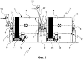
на Фиг.1 представлен схематичный чертеж установки для измельчения непрерывного действия согласно изобретению,Figure 1 presents a schematic drawing of a continuous grinding mill according to the invention,
на Фиг.2 подробно показана соединительная система между измельчителями согласно изобретению.figure 2 shows in detail the connecting system between the grinders according to the invention.
Как показано на чертежах, установка для измельчения по данному изобретению, в целом обозначенная цифрой 1, содержит множество измельчителей 2 непрерывного действия, расположенных последовательно.As shown in the drawings, the grinding apparatus of this invention, generally indicated by the number 1, comprises a plurality of
Каждый измельчитель 2 содержит вращающийся барабан 3, который образован цилиндрическим корпусом 4 с горизонтальной осью вращения, при этом корпус 4 закрыт с одного конца первым днищем 5, снабженным аксиальный горловиной 6, служащей для загрузки материала, а с противоположного конца корпус закрыт днищем 7, снабженным аксиальной горловиной 8, служащей для разгрузки суспензии.Each
С каждого из концов вращающийся барабан 3 поддерживается соответствующей конструкцией 9 и приводится в действие при помощи специальной системы управления 10 посредством ременной системы 11.At each end, the rotating
Внутри вращающегося барабана 3 расположена камера для измельчения, внутрь которой помещают как тела измельчения, так и исходные материалы, из которых будет состоять суспензия, то есть, по сути, воду, кремнезем, полевой шпат, глину. Тела измельчения обычно изготовлены из кремния или алюминия и подвергаются износу во время работы установки при смешении с суспензией в процессе обработки.A grinding chamber is located inside the rotating
На Фиг.1 показано, что предшествующий (расположенный сначала в серии) первый измельчитель 2 снабжен обычной системой 18 для загрузки исходных материалов, которая является известной, при этом загрузочная горловина 6 второго измельчителя, а также любого другого измельчителя, расположенного дальше, соединена как с разгрузочной горловиной 8 предшествующего измельчителя, так и с загрузочной трубкой 20, которая соединена с дополнительным загрузочным устройством 21.Figure 1 shows that the previous (located first in the series)
Загрузочная трубка позволяет отдельно добавлять тела измельчения в каждый измельчитель 2 непрерывного действия, а также позволят отдельно (независимо) вводить материалы или воду, что дает возможность постоянно корректировать состав смеси и обеспечить ее оптимальный состав.The loading tube allows you to separately add the grinding body in each
Каждый из измельчителей 2 непрерывного действия установки 1 для измельчения, так как он работает независимо от других, имеет оптимальный размер и оптимизирован с позиций геометрии, размеров тел измельчения и скорости вращения так, чтобы адаптировать его параметры к конкретной стадии измельчения, для выполнения которой он предназначен, при этом обрабатываемая суспензия непрерывно поступает из вращающегося барабана 3 к последующему вращающемуся барабану 3 без прерывания работы до тех пор, пока не будут достигнуты желаемые гранулометрические характеристики суспендированных порошков.Each of the
Извлечение измельченной суспензии из камеры для измельчения вращающегося барабана 3 осуществляют при помощи обычных приспособлений известного типа, которые далее не описаны подробно. Однако для целей понимания данного изобретения подчеркивается, что несмотря на то, что приспособления для извлечения перемещают суспензию по направлению к последующему вращающемуся барабану 3, такое перемещение также осуществляется и ему придается эффективность посредством вращения разгрузочной горловины 8 и загрузочной горловины 6, которые прочно присоединены к соответствующим вращающимся барабанам 3.The extraction of the crushed suspension from the chamber for grinding the rotating
Как было указано ранее, неподвижный трубчатый соединительный элемент 19 расположен между разгрузочной горловиной 8 и загрузочной горловиной 6, при этом соединительный элемент 19 состоит, в основном, из трубки, соединенной с опорной конструкцией 9 при помощи жесткого держателя 25.As mentioned earlier, a fixed tubular connecting
Перечисленные ниже детали соединены с неподвижным трубчатым соединительным элементом 19 с возможностью вращения: с одной стороны, разгрузочная горловина 8, с другой стороны - загрузочная горловина 6. Если описывать подробно, свободный конец разгрузочной горловины 8 введен аксиально внутрь канала трубчатого соединительного элемента 19, который, в свою очередь, введен внутрь канала свободного конца загрузочной горловины 6.The parts listed below are rotatably connected to the fixed tubular connecting element 19: on the one hand, the
Таким образом, разгрузочная горловина 8 меньше, чем неподвижный соединительный элемент 19, тогда как соединительный элемент 19 меньше, чем загрузочная горловина 6.Thus, the
Между разгрузочной горловиной 8, трубчатым соединительным элементом 19 и загрузочной горловиной 6 могут быть помещены подходящие приспособления для создания герметичности, при этом приспособления для создания герметичности могут вносить весомый вклад в предотвращение вытекания материала из установки 1.Between the
В частности, как показано на Фиг.2, первое спиралеобразное тело 23 присоединено к свободному концу разгрузочной горловины 8 и к ее внешней поверхности, в результате чего образуется первое винтовое устройство согласно изобретению.In particular, as shown in FIG. 2, the first spiral-
Таким образом, первое спиралеобразное тело 23 поворачивается при вращении измельчителя 2 непрерывного действия, с которым связана разгрузочная горловина 8.Thus, the first spiral-
Кроме того, второе спиралеобразное тело 24 прикреплено внутри загрузочной горловины 6 последующего измельчителя, в результате чего образуется второе винтовое устройство согласно изобретению.In addition, the second spiral-
Аналогично первому спиралеобразному телу 23 второе спиралеобразное тело 24 поворачивается при вращении измельчителя 2 непрерывного действия, с которым связана загрузочная горловина 6.Similarly to the first spiral-
Во время работы установки 1 вращающиеся барабаны 3 вращаются независимо друг от друга и вовлекают во вращение, соответственно, разгрузочную горловину 8 и загрузочную горловину 6, при этом трубчатый соединительный элемент 19 остается неподвижным.During operation of the installation 1, the rotating
Первое спиралеобразное тело 23, которое присоединено к разгрузочной горловине 8, вращается внутри первой части соединительного элемента 19.The first spiral-
Первое спиралеобразное тело 23 во время перемещения материала взаимодействует с внутренней поверхностью соединительного элемента 19 и образует первое винтовое устройство, которое выполняет функцию удерживания материала внутри соединительного элемента 19, а также предотвращает незапланированный выход материала из соответствующего (ближнего) конца трубчатого соединительного элемента 19.The first spiral-
Кроме того, второе спиралеобразное тело 24, которое соединено с загрузочной горловиной 6, вращается внутри загрузочной горловины 6 и, взаимодействуя с внешней поверхностью соединительного элемента 19, образует второе винтовое устройство, которое вносит значительный вклад в предотвращение выхода материала из соответствующего (дальнего) конца трубчатого соединительного элемента 19.In addition, the second spiral-
Признаки данного изобретения также предоставляют преимущества в связи с тем фактом, что иной материал поступает внутрь соединительного элемента через загрузочную трубку 19.The features of this invention also provide advantages due to the fact that other material enters the connecting element through the
В данном изобретении, не выходя за его рамки, как они обозначены приведенной формулой, могут быть выполнены модификации и усовершенствования, продиктованные возможными предъявляемыми к нему требованиями или частными случаями.In this invention, without going beyond its scope, as indicated by the above formula, modifications and improvements dictated by possible requirements for it or special cases can be made.
Claims (7)
Applications Claiming Priority (2)
| Application Number | Priority Date | Filing Date | Title |
|---|---|---|---|
| IT000089A ITRE20060089A1 (en) | 2006-07-20 | 2006-07-20 | CONNECTION SYSTEM BETWEEN CONTINUOUS MILLS IN SERIES OF A MILLING PLANT |
| ITRE2006A000089 | 2006-07-20 |
Publications (2)
| Publication Number | Publication Date |
|---|---|
| RU2007121939A RU2007121939A (en) | 2008-12-20 |
| RU2474476C2 true RU2474476C2 (en) | 2013-02-10 |
Family
ID=38521322
Family Applications (1)
| Application Number | Title | Priority Date | Filing Date |
|---|---|---|---|
| RU2007121939/13A RU2474476C2 (en) | 2006-07-20 | 2007-06-14 | Connection system between continuous grinders arranged in line in grinding plant |
Country Status (9)
| Country | Link |
|---|---|
| EP (1) | EP1880767B1 (en) |
| CN (1) | CN101108371B (en) |
| BR (1) | BRPI0702972A (en) |
| ES (1) | ES2351857T3 (en) |
| IT (1) | ITRE20060089A1 (en) |
| MX (1) | MX2007008602A (en) |
| PL (1) | PL1880767T3 (en) |
| PT (1) | PT1880767E (en) |
| RU (1) | RU2474476C2 (en) |
Cited By (1)
| Publication number | Priority date | Publication date | Assignee | Title |
|---|---|---|---|---|
| RU2619997C1 (en) * | 2015-12-09 | 2017-05-22 | Федеральное государственное бюджетное образовательное учреждение высшего образования "Ярославский государственный технический университет" (ФГБОУ ВО "ЯГТУ") | Device for mixing and grinding solid particulate materials |
Families Citing this family (3)
| Publication number | Priority date | Publication date | Assignee | Title |
|---|---|---|---|---|
| DE202014100640U1 (en) * | 2014-02-13 | 2014-02-21 | Geisberger Gesellschaft für Energieoptimierung mbH | Device for biogas plants for crushing and grinding liquid-solid mixtures |
| CN104258938B (en) * | 2014-10-18 | 2016-06-01 | 山东鼎汇能科技股份有限公司 | Tandem continuous ball mill and ball milling method |
| IT201900015626A1 (en) * | 2019-09-05 | 2021-03-05 | Certech S P A Con Socio Unico | Continuous mill at controllable level |
Citations (5)
| Publication number | Priority date | Publication date | Assignee | Title |
|---|---|---|---|---|
| FR398908A (en) * | 1909-01-28 | 1909-06-17 | Gerhard Zarniko | Grinding system comprising several drum mills |
| FR918556A (en) * | 1945-08-17 | 1947-02-12 | Cie De Fives Lille | Improvements to ball mill installations with rotating drum |
| US2549919A (en) * | 1947-06-06 | 1951-04-24 | Smidth & Co As F L | Airswept rotary mill or drum having separate discharge means for air and ground material |
| US3942727A (en) * | 1973-04-13 | 1976-03-09 | Boliden Aktiebolag | Grinding plant |
| RU37797U1 (en) * | 2003-12-05 | 2004-05-10 | Общество с ограниченной ответственностью Инженерный центр "Альтерэн" | PIPE ASSEMBLY ASSEMBLY (OPTIONS) |
Family Cites Families (3)
| Publication number | Priority date | Publication date | Assignee | Title |
|---|---|---|---|---|
| FR2793168B1 (en) * | 1999-05-07 | 2001-06-22 | Alstom | BALL MILL |
| ITRE20050011A1 (en) * | 2005-02-11 | 2006-08-12 | Sacmi | CONNECTION SYSTEM BETWEEN CONTINUOUS MILLS IN SERIES OF A MILLING PLANT |
| ITRE20050012A1 (en) * | 2005-02-11 | 2006-08-12 | Sacmi | CONNECTION SYSTEM BETWEEN CONTINUOUS MILLS IN SERIES OF A MILLING PLANT |
-
2006
- 2006-07-20 IT IT000089A patent/ITRE20060089A1/en unknown
-
2007
- 2007-06-14 RU RU2007121939/13A patent/RU2474476C2/en active
- 2007-06-14 EP EP07110302A patent/EP1880767B1/en active Active
- 2007-06-14 PL PL07110302T patent/PL1880767T3/en unknown
- 2007-06-14 ES ES07110302T patent/ES2351857T3/en active Active
- 2007-06-14 PT PT07110302T patent/PT1880767E/en unknown
- 2007-07-16 BR BRPI0702972-1A patent/BRPI0702972A/en active IP Right Grant
- 2007-07-16 CN CN2007101364128A patent/CN101108371B/en active Active
- 2007-07-16 MX MX2007008602A patent/MX2007008602A/en active IP Right Grant
Patent Citations (5)
| Publication number | Priority date | Publication date | Assignee | Title |
|---|---|---|---|---|
| FR398908A (en) * | 1909-01-28 | 1909-06-17 | Gerhard Zarniko | Grinding system comprising several drum mills |
| FR918556A (en) * | 1945-08-17 | 1947-02-12 | Cie De Fives Lille | Improvements to ball mill installations with rotating drum |
| US2549919A (en) * | 1947-06-06 | 1951-04-24 | Smidth & Co As F L | Airswept rotary mill or drum having separate discharge means for air and ground material |
| US3942727A (en) * | 1973-04-13 | 1976-03-09 | Boliden Aktiebolag | Grinding plant |
| RU37797U1 (en) * | 2003-12-05 | 2004-05-10 | Общество с ограниченной ответственностью Инженерный центр "Альтерэн" | PIPE ASSEMBLY ASSEMBLY (OPTIONS) |
Cited By (1)
| Publication number | Priority date | Publication date | Assignee | Title |
|---|---|---|---|---|
| RU2619997C1 (en) * | 2015-12-09 | 2017-05-22 | Федеральное государственное бюджетное образовательное учреждение высшего образования "Ярославский государственный технический университет" (ФГБОУ ВО "ЯГТУ") | Device for mixing and grinding solid particulate materials |
Also Published As
| Publication number | Publication date |
|---|---|
| PT1880767E (en) | 2010-12-14 |
| MX2007008602A (en) | 2009-01-07 |
| BRPI0702972A (en) | 2008-03-04 |
| PL1880767T3 (en) | 2011-03-31 |
| CN101108371A (en) | 2008-01-23 |
| EP1880767A1 (en) | 2008-01-23 |
| CN101108371B (en) | 2010-09-29 |
| EP1880767B1 (en) | 2010-09-22 |
| ES2351857T3 (en) | 2011-02-11 |
| ITRE20060089A1 (en) | 2008-01-21 |
| RU2007121939A (en) | 2008-12-20 |
Similar Documents
| Publication | Publication Date | Title |
|---|---|---|
| KR101575027B1 (en) | Stirring ball mill | |
| RU2394650C2 (en) | System communicating continuous-operation grinders arranged in series in grinding unit | |
| RU2474476C2 (en) | Connection system between continuous grinders arranged in line in grinding plant | |
| CN206474073U (en) | A kind of dual crushing, stirring mixing apparatus of chemical material | |
| JP2011045809A (en) | Mill | |
| US8079535B2 (en) | Method for recovering ore | |
| WO2008129384A1 (en) | Grinding system | |
| CN108284521A (en) | A kind of cement material stirring drying and crushing processing unit (plant) | |
| CN107597291A (en) | A kind of material for organic fertilizer production removes magnetic crushing device | |
| SE9404159D0 (en) | Grinding procedure and milling | |
| CA2666221C (en) | Method for introducing waste and/or alternative fuels into a clinker production method and device for carrying out said method | |
| CN202162050U (en) | Multi-roll circulation cutting-typed cracking processing equipment | |
| KR20000001804A (en) | Processing unit of sludge for water and sanitary sewage | |
| US3894692A (en) | Process and apparatus for the preparation of asbestos cement suspension | |
| CN216558069U (en) | Refining agent mixing and drying device | |
| CN210993077U (en) | Stirring structure of single-cone crystallization dryer discharge port | |
| KR20140069700A (en) | A manufacturing device for scrapped stones | |
| CN220405838U (en) | Raw material ball milling device | |
| KR100364899B1 (en) | Dry pulverizer for producing cellulose ether | |
| JPH0235944A (en) | Device for heating treatment of solid or solid-liquid mixture | |
| FI63536C (en) | APPARAT FOER AKTIVERING AV CEMENT | |
| SU1237150A1 (en) | Apparatus for drying loose products | |
| JPH09225331A (en) | Ball mill for grinding ceramic raw material and supply of raw material to ball mill | |
| SU1250382A1 (en) | Activator-mixer | |
| RU2252077C1 (en) | Roller centrifugal mill |