RU2467894C2 - Method and device for control of transport facility with tipping body - Google Patents
Method and device for control of transport facility with tipping body Download PDFInfo
- Publication number
- RU2467894C2 RU2467894C2 RU2010104391/11A RU2010104391A RU2467894C2 RU 2467894 C2 RU2467894 C2 RU 2467894C2 RU 2010104391/11 A RU2010104391/11 A RU 2010104391/11A RU 2010104391 A RU2010104391 A RU 2010104391A RU 2467894 C2 RU2467894 C2 RU 2467894C2
- Authority
- RU
- Russia
- Prior art keywords
- lifting
- moment
- control
- predetermined state
- determining
- Prior art date
Links
Images


Classifications
-
- B—PERFORMING OPERATIONS; TRANSPORTING
- B60—VEHICLES IN GENERAL
- B60P—VEHICLES ADAPTED FOR LOAD TRANSPORTATION OR TO TRANSPORT, TO CARRY, OR TO COMPRISE SPECIAL LOADS OR OBJECTS
- B60P1/00—Vehicles predominantly for transporting loads and modified to facilitate loading, consolidating the load, or unloading
- B60P1/04—Vehicles predominantly for transporting loads and modified to facilitate loading, consolidating the load, or unloading with a tipping movement of load-transporting element
- B60P1/28—Tipping body constructions
- B60P1/283—Elements of tipping devices
Landscapes
- Engineering & Computer Science (AREA)
- Transportation (AREA)
- Mechanical Engineering (AREA)
- Operation Control Of Excavators (AREA)
- Forklifts And Lifting Vehicles (AREA)
Abstract
Description
Область техники, к которой относится изобретениеFIELD OF THE INVENTION
Настоящее изобретение относится к способу управления транспортным средством с самосвальным кузовом. Настоящее изобретение относится также к устройству для управления транспортным средством с самосвальным кузовом. Кроме того, изобретение относится к различным типам транспортных средств с поворотным самосвальным кузовом, таким как, например, самосвалы, в том числе самосвалы с шарнирным сочленением.The present invention relates to a method for driving a tipper vehicle. The present invention also relates to a device for driving a dump truck. In addition, the invention relates to various types of vehicles with a swiveling tipper body, such as, for example, dump trucks, including articulated dump trucks.
Уровень техникиState of the art
В связи с транспортировкой тяжелых грузов часто используются машины типа самосвалов с шарнирным сочленением. Такие транспортные средства могут перевозить большие и тяжелые грузы в тех областях, где отсутствуют дороги, например, для транспортировки грузов в связи со строительством дороги или туннеля, в песчаных карьерах, в шахтах и в аналогичных условиях.In connection with the transportation of heavy loads, articulated dump trucks are often used. Such vehicles can carry large and heavy loads in areas where there are no roads, for example, for transporting goods in connection with the construction of a road or tunnel, in sand pits, in mines and under similar conditions.
Самосвал с шарнирным сочленением снабжен гидравлической системой для перемещения поворотного самосвального кузова между нижним и верхним положениями. Самосвальный кузов соединяется с рамой транспортного средства с помощью шарнира в задней части транспортного средства, и между рамой и кузовом установлены два гидравлических цилиндра для его поворота.The articulated dump truck is equipped with a hydraulic system to move the swiveling tipper body between the lower and upper positions. The tipper body is connected to the vehicle frame via a hinge at the rear of the vehicle, and two hydraulic cylinders are mounted between the frame and the body for turning it.
Обычно оператор транспортного средства управляет процессом поворота кузова с помощью органа управления, например с помощью рычага наклона. В процессе поворота самосвального кузова он поднимается вверх до предела (самое верхнее положение) и затем возвращается на свое место (самое нижнее положение).Typically, the operator of the vehicle controls the process of turning the body with the help of a control, for example using a tilt lever. In the process of turning the tipper body, it rises up to the limit (the highest position) and then returns to its place (the lowest position).
Самосвал с шарнирным сочленением часто используется для выполнения некоторого цикла работы. То есть, работающая машина может проходить по некоторому пути и поднимать самосвальный кузов для его разгрузки. Рабочий цикл повторяется в одной и той же географической зоне. Один из примеров рабочего цикла может включать загрузку самосвала в первой позиции, проезд по некоторому пути, который может изменяться, разгрузку во второй позиции и возвращение по тому же пути. Обычно кузов самосвала загружается в первой позиции экскаватором или колесным погрузчиком. Самосвал разгружается путем поворота самосвального кузова.The articulated dump truck is often used to complete some work cycle. That is, a working machine can go along some path and lift a tipper body to unload it. The duty cycle is repeated in the same geographical area. One example of a duty cycle may include loading a dump truck in the first position, driving along some path that may change, unloading in the second position, and returning along the same path. Typically, the truck body is loaded in the first position by an excavator or wheel loader. The tipper is unloaded by turning the tipper body.
В документе ЕР 1286850 В1 описывается полуавтоматическая система, содействующая работе самосвала с шарнирным сочленением при выполнении операции поворота кузова. В этой системе автоматически включаются тормоза, и коробка передач автоматически переключается в нейтральное положение, когда оператор нажимает кнопку включения поворота кузова.EP 1286850 B1 describes a semi-automatic system that facilitates the operation of a articulated dump truck when performing a body swivel operation. In this system, the brakes automatically turn on and the gearbox automatically shifts to the neutral position when the operator presses the body turn enable button.
Краткое изложение сущности изобретенияSummary of the invention
Первой целью изобретения является создание способа, обеспечивающего условия повышения производительности работы за счет сокращения продолжительности рабочего цикла.The first objective of the invention is to provide a method that provides conditions for increasing productivity by reducing the duration of the working cycle.
Указанная цель достигается с помощью способа, охарактеризованного в п.1 формулы изобретения. Способ включает: контроль (мониторинг) содержимого самосвального кузова в процессе его подъема, определение момента достижения заданного состояния кузова в процессе его подъема и управление транспортным средством, когда определено, что кузов достиг заданного состояния.This goal is achieved using the method described in claim 1 of the claims. The method includes: monitoring (monitoring) the contents of the tipper body in the process of lifting it, determining the moment of reaching a predetermined state of the body in the process of lifting it, and controlling the vehicle when it is determined that the body has reached a given state.
Выражение "контроль (мониторинг) самосвального кузова в процессе его подъема" относится к прямому или опосредованному контролю содержимого кузов.The expression "control (monitoring) of the tipper body during its lifting" refers to the direct or indirect control of the contents of the body.
В соответствии с предпочтительным вариантом осуществления изобретения заданное состояние кузова представляет собой состояние пустого кузова. Выражение "состояние пустого кузова" относится к состоянию, в котором практически все содержимое кузова (материал/земля) выгружено из его внутренней части. Подъем самосвального кузова может быть прекращен сразу же, как только из него выгружен материал. Поскольку во многих случаях самосвальный кузов разгружается при угле наклона, который существенно меньше максимального угла наклона, то продолжительность цикла поворота кузова существенно уменьшается.According to a preferred embodiment of the invention, the predetermined state of the body is an empty body state. The expression "empty body condition" refers to a state in which virtually all of the contents of the body (material / earth) are unloaded from its interior. The tipper body can be lifted as soon as material is unloaded from it. Since in many cases the tipper body is unloaded at a tilt angle that is substantially less than the maximum tilt angle, the cycle time of the body rotation is significantly reduced.
В соответствии с другим вариантом осуществления изобретения заданное состояние определяется как момент времени, когда материал начинает соскальзывать вниз из кузова. Такой вариант предпочтительно может использоваться в тех случаях, когда разгружаемый материал легко соскальзывает вниз при подъеме кузова. Примером такого материала является гравий. Таким образом, подъем кузова может быть прекращен сразу же, как только материал придет в движение, и кузов может поддерживаться в таком положении, пока из него не высыплется весь материал.In accordance with another embodiment of the invention, a predetermined state is defined as the point in time when the material begins to slide down from the body. This option can preferably be used in cases where the discharged material easily slides down when lifting the body. An example of such a material is gravel. Thus, the lifting of the body can be stopped immediately, as soon as the material comes into motion, and the body can be maintained in such a position until all material has spilled out of it.
Способ создает условия для повышения производительности и безопасности работ за счет содействия процессу выгрузки. Это достоинство способа особенно ощутимо для операторов с небольшим опытом работы.The method creates conditions for increasing productivity and safety of work by facilitating the unloading process. This advantage of the method is especially noticeable for operators with little work experience.
Выражение "управление транспортным средством" относится к любому виду управления, такому как управление поворотом самосвального кузова и/или другими системами транспортного средства, например силовой частью для обеспечения его движения. Предпочтительно осуществляется управление процессом выгрузки материала из кузова. Например, силовая часть транспортного средства может обеспечивать его продвижение таким образом, что материал будет разгружаться регулируемым образом на некотором расстоянии, предпочтительно рассыпаться ровным слоем по поверхности. В предпочтительном варианте транспортное средство подается вперед с определенной скоростью. Подъем самосвального кузова и работа силовой части могут осуществляться одновременно.The term "vehicle control" refers to any type of control, such as controlling the rotation of a tipper body and / or other systems of the vehicle, for example, the power unit to ensure its movement. Preferably, the process of unloading material from the body is controlled. For example, the power part of the vehicle can ensure its advance in such a way that the material will be unloaded in an adjustable manner at a certain distance, preferably it will scatter evenly over the surface. In a preferred embodiment, the vehicle is driven forward at a certain speed. The lifting of the tipper body and the operation of the power unit can be carried out simultaneously.
В соответствии с предпочтительным вариантом способ включает автоматическое опускание кузова, когда определено, что он достиг состояния пустого кузова. За счет автоматического опускания самосвального кузова сразу же, как только из него будет выгружен материал, достигается дополнительное сокращение общего времени цикла работы.According to a preferred embodiment, the method includes automatically lowering the body when it is determined that it has reached an empty body state. Due to the automatic lowering of the tipper body as soon as the material is unloaded from it, an additional reduction in the overall cycle time is achieved.
В предпочтительном варианте способ включает контроль грузоприемной части кузова в процессе его подъема и определение момента опустошения кузова по результатам такого контроля. Таким образом, осуществляется контроль внутренней части самосвального кузова для определения момента его полной разгрузки.In a preferred embodiment, the method includes monitoring the load-receiving part of the body during its lifting and determining the moment of emptying of the body according to the results of such control. Thus, the internal part of the tipper body is monitored to determine when it is completely unloaded.
Еще по одному предпочтительному варианту осуществления изобретения способ включает измерение давления в гидравлическом цилиндре, обеспечивающем поворот кузова, и определение момента достижения заданного состояния кузова на основании результатов такого измерения. В предпочтительном варианте способ включает установление заданного состояния, когда измерено определенное изменение давления. Предпочтительно изменение давления задается в качестве индикатора заданного состояния.In yet another preferred embodiment of the invention, the method includes measuring the pressure in the hydraulic cylinder to rotate the body and determining when the desired state of the body is reached based on the results of such a measurement. In a preferred embodiment, the method includes establishing a predetermined state when a specific pressure change is measured. Preferably, the pressure change is set as an indicator of a predetermined state.
Второй целью изобретения является создание устройства, обеспечивающего условия повышения производительности работы за счет сокращения продолжительности рабочего цикла.The second objective of the invention is to provide a device that provides conditions for increasing productivity by reducing the duration of the working cycle.
Указанная цель достигается с помощью устройства, охарактеризованного в соответствующем независимом пункте формулы изобретения. Устройство содержит: средство автоматического контроля содержимого самосвального кузова в процессе его подъема, а также средство определения момента достижения заданного состояния кузова в процессе его подъема и управления транспортным средством, когда определено, что кузов достиг заданного состояния. Другие достоинства и преимущества, а также функции различных вариантов осуществления изобретения рассмотрены в нижеприведенном описании и в зависимых пунктах формулы изобретения.This goal is achieved using the device described in the corresponding independent claim. The device comprises: means for automatically controlling the contents of the tipper body during its lifting, as well as means for determining the moment of reaching a predetermined state of the body during its lifting and driving, when it is determined that the body has reached a given state. Other advantages and advantages, as well as the functions of various embodiments of the invention are discussed in the description below and in the dependent claims.
Краткое описание чертежейBrief Description of the Drawings
Изобретение описывается ниже на примерах некоторых вариантов его осуществления, которые иллюстрируются на прилагаемых чертежах, на которых показано:The invention is described below with examples of some variants of its implementation, which are illustrated in the accompanying drawings, which show:
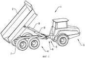
на фиг.1 - вид в перспективе самосвала с шарнирным сочленением с поднятым самосвальным кузовом;figure 1 is a perspective view of a truck with articulated articulation with a raised tipper body;
на фиг.2 - вид сбоку самосвального кузова в двух крайних положениях;figure 2 is a side view of the tipper body in two extreme positions;
на фиг.3 - блок-схема гидравлической системы в соответствии с первым вариантом осуществления изобретения;figure 3 is a block diagram of a hydraulic system in accordance with the first embodiment of the invention;
на фиг.4 - блок-схема системы управления процессом поворота кузова.figure 4 is a block diagram of a process control system for turning the body.
Варианты осуществления изобретенияEmbodiments of the invention
На фиг.1 показан вид в перспективе самосвала, в частности самосвала 1 с шарнирным сочленением, с поднятым самосвальным кузовом 2. Самосвал 1 содержит переднюю часть 3, состоящую из передней рамы, передней оси и кабины водителя. Самосвал 1 содержит также заднюю часть 4, состоящую из задней рамы, двух осей и поворотного самосвального кузова или контейнера 2.Figure 1 shows a perspective view of a dump truck, in particular a articulated dump truck 1, with a
Передняя рама соединяется с задней рамой с помощью первого шарнира 5, который обеспечивает поворот рам относительно друг друга вокруг вертикальной оси для обеспечения управления направлением движения самосвала. По сторонам шарнира расположены два гидравлических цилиндра (не показаны), обеспечивающих управление направлением движения самосвалом. Управление работой гидравлических цилиндров осуществляет водитель самосвала с помощью рулевого колеса и/или ручки управления (не показаны).The front frame is connected to the rear frame using the
Между передней и задней рамами имеется также второй шарнир 6, обеспечивающий возможность поворота рам относительно друг друга вокруг продольной оси самосвала.Between the front and rear frames there is also a
Поворотный самосвальный кузов 2 соединяется с задней рамой с помощью шарнира 7, установленного на задней части задней рамы. Самосвал снабжен двумя гидравлическими поворотными цилиндрами 8, 9, первые концы которых соединяются с задней рамой и вторые концы соединяются с самосвальным кузовом 2. Поворотные цилиндры 8, 9 установлены по обеим сторонам центральной продольной оси самосвала. Таким образом, самосвальный кузов 2 поворачивается относительно задней рамы при включении поворотных цилиндров 8, 9.The
Обычно самосвальный кузов 2 представляет собой коробчатую конструкцию с закрытыми нижней, передней и боковыми стенками и открытым верхом. В процессе разгрузки содержимое кузова соскальзывает из него на землю или в соответствующий приемник груза.Typically, the
На фиг.2 самосвальный кузов 5 показан в двух крайних положениях: в полностью опущенном положении и в полностью поднятом положении (показано штрихпунктирными линиями). В полностью поднятом положении кузов находится под максимальным углом поворота (подъема) α. На самосвальном кузове 2 установлено средство 31 контроля состояния внутренней части кузова. Такое средство 31 может представлять собой радиолокационный аппарат. Электромагнитные волны, излучаемые средством 31 контроля, показаны пунктирными линиями. Как показано на фиг.2, в кузове 2 остался налипший материал 32.In Fig.2, the
На фиг.3 показана гидравлическая система 101 в соответствии с первым вариантом работы гидравлических цилиндров 8, 9. Гидравлическая система 101 содержит насос 10, предназначенный для подачи гидравлической текучей среды под давлением в гидравлические цилиндры 8, 9 из резервуара 11 по трубопроводам 15, 16, 17. Поворотные цилиндры 8, 9 устроены таким образом, чтобы они двигались синхронно в процессе поворота кузова.Figure 3 shows the
Между насосом 10 и гидравлическими цилиндрами 8, 9 в линии 15 установлен первый клапан 12, представляющий собой направляющий клапан-распределитель. В первом положении клапан 12 направляет текучую среду по линии 16 на стороны 18, 19 поршней цилиндров, и во втором положении направляет текучую среду по линии 17 на стороны 20, 21 поршней цилиндров. Когда поток текучей среды направляется по линии 16 на стороны 18, 19 поршней, соответствующий поток будет вытекать со сторон 20, 21 поршней по линии 17 через направляющий клапан-распределитель в резервуар 11, и наоборот. Направляющий клапан-распределитель 12 имеет три положения, причем в промежуточном положении текучая среда через клапан не протекает.Between the
В альтернативном варианте в качестве клапана-распределителя может использоваться четырехпозиционный направляющий клапан-распределитель. В дополнение к трем вышеуказанным положениям такой клапан имеет четвертое положение, в котором пространство с обеих сторон поршней соединяется со средой, находящейся под атмосферным давлением, например с резервуаром текучей среды с плавающей крышкой. Достоинством такого решения является то, что при транспортировке давление в гидравлической системе сбрасывается.Alternatively, a four-way directional control valve may be used as the control valve. In addition to the three above-mentioned positions, such a valve has a fourth position in which the space on both sides of the pistons is connected to a medium under atmospheric pressure, for example, to a fluid reservoir with a floating cover. The advantage of this solution is that during transportation, the pressure in the hydraulic system is released.
На фиг.4 приведена блок-схема системы управления процессом поворота кузова по одному из вариантов. Система управления содержит контроллер 25 или электронный блок управления. Средство 31 контроля вырабатывает сигнал, содержащий информацию о состоянии (наличие материала) поворотного кузова 2, и передачу его в контроллер 25. Контроллер 25 на основании полученного сигнала принимает решение о продолжении или прекращении поворота кузова. Кроме того, в соответствии с принятым решением контроллер 25 осуществляет управление гидравлической системой 101. Более конкретно, контроллер 25 осуществляет управление работой клапана 12. С контроллером 25 функционально соединена силовая часть 26, содержащая двигатель 27 и коробку 28 передач. Кроме того, с контроллером 26 функционально соединено средство 29 предотвращения движения самосвала.Figure 4 shows a block diagram of a control system for the process of turning the body according to one of the options. The control system comprises a
В соответствии с одним из вариантов осуществления изобретения (см. фиг.2-4) способ включает определение наличия материала, остающегося в кузове в процессе его подъема для принятия решения о прекращении поворота кузова. Таким образом, сначала определяется, остается ли еще материал в самосвальном кузове 2, когда он находится в поднятом положении. Способ включает определение с помощью радиолокационного устройства состояния груза в самосвальном кузове 2 в процессе его подъема и принятие решения на основании полученной информации о том, что кузов пуст. Подъем кузова прекращается сразу же, как только будет определено, что самосвальный кузов 2 пуст. После этого кузов 2 сразу же опускается в его самое нижнее положение.In accordance with one embodiment of the invention (see FIGS. 2-4), the method includes determining the presence of material remaining in the body during its lifting to make a decision to stop turning the body. Thus, it is first determined whether there is still material in the
В соответствии с одним из альтернативных вариантов, способ содержит определение состояния груза в самосвальном кузове 2 в процессе его подъема с помощью оптического устройства и принятие решения на основе полученной информации о том, что кузов 2 пуст. В качестве такого оптического устройства может использоваться телекамера.In accordance with one alternative option, the method comprises determining the state of the load in the
Еще в одном варианте осуществления изобретения в процессе подъема самосвального кузова 2 определяется вес материала в кузове, и на основе полученной информации о весе груза принимается решение о том, что кузов 2 пуст. Вес может определяться различными способами, такими как, например, использование тензометрического датчика в шарнире кузова или измерение давления в гидравлической системе 101, 201.In another embodiment of the invention, the weight of the material in the body is determined in the process of lifting the
В соответствии с другим вариантом после получения пускового сигнала, например, переданного органом, управляемым оператором, таким как, например, кнопка включения поворота кузова, автоматически выполняются следующие стадии, прежде чем будут выполняться действия, указанные выше:In accordance with another option, after receiving a start signal, for example, transmitted by a body controlled by an operator, such as, for example, a button for turning on a body turn, the following stages are automatically performed before the actions described above are performed:
1. Удерживание транспортного средства в неподвижном состоянии путем включения средств 29 предотвращения движения, например, одного или нескольких тормозных устройств. Предпочтительно включаются основные тормоза (тормоза колес). В качестве дополнительного или альтернативного средства может включаться стояночный тормоз.1. Keeping the vehicle stationary by turning on the
2. Установка коробки 28 передач в нейтральное положение.2. Installing
В соответствии с еще одним вариантом после первых действий автоматически выполняются следующие действия:In accordance with another option, after the first actions, the following actions are automatically performed:
1. Управление двигателем 27 для установки оптимальной скорости работы для привода насоса 10 гидравлической системы 101, обеспечивающей подъем самосвального кузова.1. Control of the
2. Подъем самосвального кузова 2 с помощью гидравлической системы.2. Lifting the
В процессе подъема кузова осуществляются указанные выше стадии контроля груза и прекращения поворота. А именно:In the process of lifting the body, the above stages of cargo control and stopping the turn are carried out. Namely:
1. Определение момента, когда в процессе подъема кузова из него высыпался весь груз (состояние пустого кузова).1. Determination of the moment when, during the lifting of the body, the whole load fell out of it (state of an empty body).
2. Прекращение подъема кузова после определения достижения состояния пустого кузова. В процессе подъема самосвального кузова осуществляется непрерывный контроль его состояния.2. Stop lifting the body after determining the achievement of an empty body. In the process of lifting a tipper body, continuous monitoring of its condition is carried out.
В соответствии еще с одним вариантом после прекращения подъема кузова автоматически выполняется следующая стадия:In accordance with another option, after the cessation of the lifting of the body, the following stage is automatically performed:
1. Опускание самосвального кузова после определения того, что он находится в состоянии пустого кузова.1. Lowering the tipper body after determining that it is in an empty body condition.
В соответствии еще с одним вариантом после прекращения подъема кузова автоматически выполняются следующие стадии (одна или несколько):In accordance with another option, after the cessation of the lifting of the body, the following stages (one or more) are automatically performed:
1. Перевод двигателя в режим холостого хода.1. Putting the engine into idle mode.
2. Включение передней передачи, прежде чем кузов достигнет своего самого нижнего положения.2. Putting forward gear before the body reaches its lowest position.
3. Выключение тормозных устройств.3. Turn off the brake devices.
4. Обеспечение движения самосвала с заданной максимальной скоростью сразу же, после того как угол наклона кузова станет меньше заданной величины, которая близка величине угла наклона кузова в его самом нижнем положении, однако кузов при этом еще не находится в этом крайнем нижнем положении. Ограничение максимальной скорости устанавливается до достижения кузовом его самого нижнего положения. То обстоятельство, что самосвал начинает двигаться, является указанием для оператора того, что операция разгрузки закончена, и он может уезжать.4. Ensuring the movement of the truck with a given maximum speed immediately after the tilt angle of the body becomes less than the specified value, which is close to the value of the tilt angle of the body in its lowest position, however, the body is still not in this extreme lower position. The maximum speed limit is set until the body reaches its lowest position. The fact that the dump truck begins to move is an indication to the operator that the unloading operation is completed and he can leave.
Таким образом, все действия, необходимые для разгрузки самосвального кузова 2, могут быть выполнены в автоматическом режиме. Таким образом, оператору необходимо только остановить самосвал в нужном месте и включить систему.Thus, all the steps necessary for unloading the
Для включения системы используются средства управления оператора, такие как рычаг (или ручка) или две кнопки. Отклонение рычага в первом направлении вызывает формирование и передачу пускового сигнала на выполнение последовательности стадий способа. Последовательность стадий выполняется, пока рычаг удерживается в отклоненном положении. С другой стороны, отклонение рычага в другом направлении вызывает формирование и передачу сигнала останова, в результате чего выполнение последовательности действий прекращается, и самосвальный кузов возвращается в его крайнее нижнее положение, предпочтительно в автоматическом режиме. В случае использования двух кнопок аналогичное управление осуществляется за счет того, что сигналы, вырабатываемые при нажатии кнопок, соответствуют сигналам, вырабатываемым при отклонении рычага в одном или в другом направлениях.To turn on the system, operator controls are used, such as a lever (or knob) or two buttons. The deviation of the lever in the first direction causes the formation and transmission of the trigger signal to perform the sequence of stages of the method. The sequence of steps is performed while the lever is held in a deviated position. On the other hand, the deviation of the lever in the other direction causes the formation and transmission of a stop signal, as a result of which the sequence of actions stops, and the tipper body returns to its lowermost position, preferably in automatic mode. In the case of using two buttons, the same control is carried out due to the fact that the signals generated when the buttons are pressed correspond to the signals generated when the lever is deflected in one or the other direction.
В предпочтительном варианте, прежде чем включать систему, обеспечивается остановка самосвала, или же скорость его движения должна быть меньше заданного порогового значения, близкого к нулю.In a preferred embodiment, before turning on the system, the truck is stopped, or its speed should be less than a predetermined threshold value close to zero.
В соответствии с другим вариантом самосвальный кузов подвергается действию вибрации для облегчения удаления прилипшего материала, когда кузов находится в поднятом положении. Таким образом, если при некотором угле наклона, например, в самом верхнем положении, содержимое кузова не полностью выгружено из него, то кузов подвергается действию вибрации. В предпочтительном варианте гидравлические цилиндры 8, 9 действуют таким образом, что они создают вибрацию самосвального кузова. Предпочтительно это осуществляется путем циклического изменения подачи гидравлической текучей среды на стороны 18, 19 и 20, 21 поршней гидравлических цилиндров 8, 9. Это действие может быть выполнено путем циклического переключения клапана 12 между его двумя крайними положениями. Предпочтительная частота вибрации кузова самосвала находится в диапазоне 20-40 Гц.In another embodiment, the tipper body is subjected to vibration to facilitate removal of adhering material when the body is in a raised position. Thus, if at a certain angle of inclination, for example, in the uppermost position, the contents of the body are not completely unloaded from it, then the body is exposed to vibration. In a preferred embodiment, the
В соответствии еще с одним вариантом вибрация создается в течение части или всего цикла подъема кузова 2 самосвала.In accordance with yet another embodiment, vibration is generated during part or all of the lifting cycle of the
В соответствии еще с одним вариантом осуществления изобретения вместо автоматического включения режима вибрации кузова самосвала он включается оператором вручную с помощью органа управления в том случае, когда в кузове, достигшем своего самого верхнего положения, еще имеется выгружаемый материал.In accordance with another embodiment of the invention, instead of automatically turning on the vibration mode of the dump truck body, it is manually activated by the operator using the control element in the case when there is still unloading material in the body that has reached its highest position.
Кроме того, в одном из альтернативных вариантов вместо автоматического опускания кузова самосвала используется ручное включение опускания кузова оператором с помощью органа управления.In addition, in one of the alternatives, instead of automatically lowering the body of the dump truck, manual inclusion of the lowering of the body by the operator using the control is used.
В соответствии с другими вариантами информация о текущем положении кузова самосвала и/или состоянии груза отображается в кабине оператора.In accordance with other options, information about the current position of the dump truck body and / or the state of the load is displayed in the operator's cab.
В качестве предохранительной меры для предотвращения возможности опрокидывания самосвала осуществляется контроль угла его наклона, максимальный допустимый угол поворота кузова определяется (вычисляется) в зависимости от текущего угла наклона (и предпочтительно с учетом информации о грузе), и подъем кузова автоматически прекращается, когда угол поворота достигает максимально допустимого значения.As a precautionary measure to prevent the truck from tipping over, its angle of inclination is monitored, the maximum permissible angle of rotation of the body is determined (calculated) depending on the current angle of inclination (and preferably taking into account information about the load), and the lifting of the body automatically stops when the angle of rotation reaches the maximum allowable value.
В предпочтительном варианте осуществления изобретения контроллер реализуется в микропроцессоре. Контроллер содержит запоминающее устройство, которое, в свою очередь, содержит компьютерную программу, состоящую из сегментов, для осуществления способа управления при выполнении программы. Эта компьютерная программа может быть передана в контроллер различными способами, например, путем скачивания из другого компьютера, по проводной или беспроводной линии связи, или установкой платы памяти. В частности, может быть осуществлена передача программы по сети Интернет.In a preferred embodiment, the controller is implemented in a microprocessor. The controller contains a storage device, which, in turn, contains a computer program consisting of segments for implementing the control method when the program is executed. This computer program can be transferred to the controller in various ways, for example, by downloading from another computer, via a wired or wireless communication line, or by installing a memory card. In particular, a program may be transmitted over the Internet.
Изобретение никоим образом не ограничивается рассмотренными выше вариантами его осуществления, и возможно использование других вариантов или модификаций без выхода за пределы объема, определяемого нижеприведенной формулой изобретения.The invention is in no way limited to the above options for its implementation, and it is possible to use other options or modifications without going beyond the scope defined by the following claims.
Claims (15)
Applications Claiming Priority (3)
| Application Number | Priority Date | Filing Date | Title |
|---|---|---|---|
| SE0701726 | 2007-07-11 | ||
| SE0701726-2 | 2007-07-11 | ||
| PCT/SE2007/001164 WO2009008785A1 (en) | 2007-07-11 | 2007-12-21 | A method and a device for controlling a vehicle comprising a dump body |
Publications (2)
| Publication Number | Publication Date |
|---|---|
| RU2010104391A RU2010104391A (en) | 2011-08-20 |
| RU2467894C2 true RU2467894C2 (en) | 2012-11-27 |
Family
ID=40228809
Family Applications (1)
| Application Number | Title | Priority Date | Filing Date |
|---|---|---|---|
| RU2010104391/11A RU2467894C2 (en) | 2007-07-11 | 2007-12-21 | Method and device for control of transport facility with tipping body |
Country Status (6)
| Country | Link |
|---|---|
| US (1) | US8267480B2 (en) |
| EP (1) | EP2167346B1 (en) |
| CN (1) | CN101730634B (en) |
| RU (1) | RU2467894C2 (en) |
| WO (1) | WO2009008785A1 (en) |
| ZA (1) | ZA200909074B (en) |
Cited By (1)
| Publication number | Priority date | Publication date | Assignee | Title |
|---|---|---|---|---|
| RU207820U1 (en) * | 2021-08-11 | 2021-11-18 | Акционерное Общество "Ряжский Авторемонтный Завод" | BODY LIFTING MECHANISM |
Families Citing this family (17)
| Publication number | Priority date | Publication date | Assignee | Title |
|---|---|---|---|---|
| WO2011089792A1 (en) * | 2010-01-20 | 2011-07-28 | 日立建機株式会社 | Conveying vehicle |
| DE102010002701A1 (en) * | 2010-03-09 | 2011-09-15 | Franz Xaver Meiller Fahrzeug- Und Maschinenfabrik - Gmbh & Co Kg | Kippzustandsüberwachung |
| US8087731B1 (en) * | 2010-09-22 | 2012-01-03 | Rogers Ralph R | Side dump body |
| US9108677B2 (en) * | 2010-10-07 | 2015-08-18 | Wrt Equipment Ltd | End dump trailer |
| US8833861B2 (en) * | 2010-12-03 | 2014-09-16 | Caterpillar Inc. | Loading analysis system and method |
| CN103314646A (en) | 2011-01-13 | 2013-09-18 | 皇家飞利浦有限公司 | Light system and method |
| US8818699B2 (en) * | 2011-02-15 | 2014-08-26 | Deere & Company | Weight-based stability detection system |
| US9937844B2 (en) * | 2012-04-11 | 2018-04-10 | Volvo Construction Equipment Ab | Method for tipping a load and a tipping device |
| US9200429B2 (en) * | 2013-10-31 | 2015-12-01 | Deere & Company | Work vehicle with loader controlled cab tilting |
| GB201503874D0 (en) * | 2015-03-06 | 2015-04-22 | Hyva Holding Bv | Method and system for operating a tipper vehicle |
| US9845039B2 (en) * | 2015-09-14 | 2017-12-19 | Caterpillar Inc. | System and method of automatically operating a hoist system for a machine |
| CN105730331B (en) * | 2016-01-13 | 2018-01-19 | 三一汽车制造有限公司 | The condition monitoring system and method for boxcar |
| CN109831075A (en) * | 2019-03-25 | 2019-05-31 | 五冶集团上海有限公司 | Tool cart is used in a kind of replacement of vibration motor |
| CN111762077A (en) * | 2020-06-10 | 2020-10-13 | 博雷顿科技有限公司 | Automatic lifting system for carriage of unmanned commercial vehicle |
| CN111619423B (en) * | 2020-06-15 | 2021-11-19 | 南京轩世琪源软件科技有限公司 | Intelligent wheat unloading device |
| US10988067B1 (en) | 2020-10-26 | 2021-04-27 | Veradyn Llc | Dump trailer and system for a semi-trailer truck |
| DE102021214119B3 (en) | 2021-12-10 | 2023-02-16 | Zf Friedrichshafen Ag | Supervision of the dumping of material |
Citations (5)
| Publication number | Priority date | Publication date | Assignee | Title |
|---|---|---|---|---|
| JPS58152635A (en) * | 1982-03-03 | 1983-09-10 | Kubota Ltd | Dump truck |
| SU1240653A1 (en) * | 1984-12-26 | 1986-06-30 | Центральный Ордена Трудового Красного Знамени Научно-Исследовательский Автомобильный И Автомоторный Институт | Device for limiting travel of dump truck hydraulic cylinder |
| US5742228A (en) * | 1993-12-24 | 1998-04-21 | Litan Advanced Instrumentation Ltd. | System for preventing tipper truck overturning |
| GB2369097A (en) * | 2000-09-12 | 2002-05-22 | Komatsu Mfg Co Ltd | System for reducing cylinder descent speed |
| US20060251502A1 (en) * | 2002-11-20 | 2006-11-09 | Kurt Scharfenberger | Commercial vehicle, especially a truck with a lifting loading platform |
Family Cites Families (13)
| Publication number | Priority date | Publication date | Assignee | Title |
|---|---|---|---|---|
| JPS5996022A (en) * | 1982-11-22 | 1984-06-02 | Komatsu Ltd | Working condition detecting apparatus for loading vehicle |
| US4614477A (en) | 1983-06-27 | 1986-09-30 | Hagenbuch Roy George Le | Apparatus and method for monitoring and controlling the volumetric loading of a truck body |
| US4630227A (en) | 1984-04-27 | 1986-12-16 | Hagenbuch Roy George Le | Apparatus and method for on-board measuring of the load carried by a truck body |
| CN1024218C (en) * | 1985-07-05 | 1994-04-13 | 勒鲁瓦·赫根布 | Apparaturs and method responsive to the on-boards measuring of the load carried by a truck body |
| US5637837A (en) * | 1994-04-15 | 1997-06-10 | Mettler-Toledo, Inc. | Platform lifting and lowering mechanism for weighing apparatus |
| US5664933A (en) * | 1996-03-26 | 1997-09-09 | Mima Incorporated | Method and apparatus for transferring a load |
| JP4028609B2 (en) * | 1996-09-24 | 2007-12-26 | 小平産業株式会社 | Device for measuring the weight of a load on a vehicle with an inclined platform |
| SE515446C2 (en) | 2000-06-05 | 2001-08-06 | Volvo Articulated Haulers Ab | Device and method for controlling specific functions of a loading vehicle when tipping and / or loading the vehicle's surface |
| US6783187B2 (en) * | 2002-10-29 | 2004-08-31 | Michael S. Parsons | Vector neutral truck |
| US20050028604A1 (en) * | 2003-08-04 | 2005-02-10 | Fathi Saigh | Sensor system for monitoring load displacements in a freight vehicle |
| CN2666734Y (en) * | 2003-12-12 | 2004-12-29 | 辽宁仪表研究所有限责任公司 | Automatic weighing device for load-carrying tip lorry |
| WO2006093438A1 (en) * | 2005-03-01 | 2006-09-08 | Volvo Construction Equipment Holding Sweden Ab | A method and an arrangement for preventing overturning a dump vehicle |
| US8371657B2 (en) * | 2010-02-12 | 2013-02-12 | Timpte, Inc. | Storage hopper assembly |
-
2007
- 2007-12-21 US US12/667,044 patent/US8267480B2/en active Active
- 2007-12-21 EP EP07852156.4A patent/EP2167346B1/en not_active Not-in-force
- 2007-12-21 RU RU2010104391/11A patent/RU2467894C2/en not_active IP Right Cessation
- 2007-12-21 WO PCT/SE2007/001164 patent/WO2009008785A1/en active Application Filing
- 2007-12-21 CN CN2007800536587A patent/CN101730634B/en not_active Expired - Fee Related
-
2009
- 2009-12-18 ZA ZA200909074A patent/ZA200909074B/en unknown
Patent Citations (5)
| Publication number | Priority date | Publication date | Assignee | Title |
|---|---|---|---|---|
| JPS58152635A (en) * | 1982-03-03 | 1983-09-10 | Kubota Ltd | Dump truck |
| SU1240653A1 (en) * | 1984-12-26 | 1986-06-30 | Центральный Ордена Трудового Красного Знамени Научно-Исследовательский Автомобильный И Автомоторный Институт | Device for limiting travel of dump truck hydraulic cylinder |
| US5742228A (en) * | 1993-12-24 | 1998-04-21 | Litan Advanced Instrumentation Ltd. | System for preventing tipper truck overturning |
| GB2369097A (en) * | 2000-09-12 | 2002-05-22 | Komatsu Mfg Co Ltd | System for reducing cylinder descent speed |
| US20060251502A1 (en) * | 2002-11-20 | 2006-11-09 | Kurt Scharfenberger | Commercial vehicle, especially a truck with a lifting loading platform |
Cited By (1)
| Publication number | Priority date | Publication date | Assignee | Title |
|---|---|---|---|---|
| RU207820U1 (en) * | 2021-08-11 | 2021-11-18 | Акционерное Общество "Ряжский Авторемонтный Завод" | BODY LIFTING MECHANISM |
Also Published As
| Publication number | Publication date |
|---|---|
| CN101730634A (en) | 2010-06-09 |
| US20100327649A1 (en) | 2010-12-30 |
| RU2010104391A (en) | 2011-08-20 |
| CN101730634B (en) | 2012-07-18 |
| EP2167346A1 (en) | 2010-03-31 |
| ZA200909074B (en) | 2010-10-27 |
| WO2009008785A1 (en) | 2009-01-15 |
| EP2167346A4 (en) | 2011-07-06 |
| EP2167346B1 (en) | 2013-10-30 |
| US8267480B2 (en) | 2012-09-18 |
Similar Documents
| Publication | Publication Date | Title |
|---|---|---|
| RU2467894C2 (en) | Method and device for control of transport facility with tipping body | |
| US8589035B2 (en) | Method for operating a transport vehicle, a transport vehicle, a method for controllling operation of a work site and a work site system | |
| US9593469B2 (en) | System and method for controlling a work vehicle based on a monitored tip condition of the vehicle | |
| JP5119363B2 (en) | Transport vehicle | |
| EP2172364B1 (en) | Transport vehicle | |
| CN102037194B (en) | Working vehicle, control device for working vehicle, and operating-oil amount control method for working vehicle | |
| EP3333325A1 (en) | Work vehicle | |
| WO2016208275A1 (en) | Wheel loader and automatic accumulation method for transport work information of wheel loader | |
| WO2009008784A1 (en) | A method and a device for dumping material from a tiltable dump body of a vehicle | |
| JPWO2008099691A1 (en) | Transport vehicle | |
| US10583736B2 (en) | System for controlling a drive operation of a machine | |
| JP3373121B2 (en) | Bulldozer dosing equipment | |
| JP2013169931A (en) | Transport vehicle | |
| EP3219542B1 (en) | Transportation vehicle | |
| WO2016085369A1 (en) | A method and control unit for preventing rollover of a tractor unit of a working machine | |
| EP2949506B1 (en) | Vehicle having automated control of a movable body | |
| US20220314860A1 (en) | System and method for moving material | |
| RU2458206C2 (en) | Method of controlling working mechanism | |
| JP2023049621A (en) | Garbage collection vehicle | |
| JP2016199175A (en) | Transportation vehicle | |
| JPH0568965U (en) | Automatic dumper for dump truck |
Legal Events
| Date | Code | Title | Description |
|---|---|---|---|
| MM4A | The patent is invalid due to non-payment of fees |
Effective date: 20171222 |