RU2465103C2 - Method of making part from blank by hobbing - Google Patents
Method of making part from blank by hobbing Download PDFInfo
- Publication number
- RU2465103C2 RU2465103C2 RU2011105412/02A RU2011105412A RU2465103C2 RU 2465103 C2 RU2465103 C2 RU 2465103C2 RU 2011105412/02 A RU2011105412/02 A RU 2011105412/02A RU 2011105412 A RU2011105412 A RU 2011105412A RU 2465103 C2 RU2465103 C2 RU 2465103C2
- Authority
- RU
- Russia
- Prior art keywords
- path
- milling tool
- cutting
- tool
- sent
- Prior art date
Links
Images


Classifications
-
- B—PERFORMING OPERATIONS; TRANSPORTING
- B23—MACHINE TOOLS; METAL-WORKING NOT OTHERWISE PROVIDED FOR
- B23C—MILLING
- B23C3/00—Milling particular work; Special milling operations; Machines therefor
-
- B—PERFORMING OPERATIONS; TRANSPORTING
- B23—MACHINE TOOLS; METAL-WORKING NOT OTHERWISE PROVIDED FOR
- B23C—MILLING
- B23C5/00—Milling-cutters
-
- Y—GENERAL TAGGING OF NEW TECHNOLOGICAL DEVELOPMENTS; GENERAL TAGGING OF CROSS-SECTIONAL TECHNOLOGIES SPANNING OVER SEVERAL SECTIONS OF THE IPC; TECHNICAL SUBJECTS COVERED BY FORMER USPC CROSS-REFERENCE ART COLLECTIONS [XRACs] AND DIGESTS
- Y10—TECHNICAL SUBJECTS COVERED BY FORMER USPC
- Y10T—TECHNICAL SUBJECTS COVERED BY FORMER US CLASSIFICATION
- Y10T409/00—Gear cutting, milling, or planing
- Y10T409/30—Milling
- Y10T409/303752—Process
- Y10T409/303808—Process including infeeding
Landscapes
- Engineering & Computer Science (AREA)
- Mechanical Engineering (AREA)
- Milling Processes (AREA)
- Numerical Control (AREA)
Abstract
Description
Изобретение относится к способу изготовления детали из заготовки посредством фрезерного инструмента.The invention relates to a method for manufacturing a part from a workpiece by means of a milling tool.
Особое управление движением фрезерного инструмента имеет особое значение при его врезании в обрабатываемый материал, как правило, тогда, когда фрезерный инструмент, главным образом, при торцевом контакте должен достигать аксиально большой подачи на глубину (на врезание). При фрезерной обработке с большой подачей на глубину в материал, например при черновой обработке, применение на практике нашли различные способы. Часто материал за отдельную операцию, как правило, посредством сверления предварительно удаляется в начальной точке так, что начальная точка обработки может аксиально достигаться без съема материала.Particular control of the movement of the milling tool is of particular importance when it is inserted into the material to be processed, as a rule, when the milling tool, mainly at the end contact, must reach an axially large depth feed (for cutting). When milling with a large feed to a depth in the material, for example during roughing, various methods have found practical application. Often the material in a single operation, usually by drilling, is preliminarily removed at the starting point so that the starting point of the treatment can be axially reached without material removal.
Если задать определенные точки врезания или их предварительную обработку невозможно, то исходя из контура заготовки в направлении начальной точки вычисляется дополнительный рампообразный или геликоидальный путь фрезерного инструмента, по которому фрезерный инструмент под плоским углом следующего обрабатываемого слоя или касательной плоскости непрерывно приближается к первой точке траектории. Соответствующие примеры обработки с жестко установленной осью фрезерного инструмента изображены на фиг.2а-2с. Для сравнения с ними следует сослаться на способ обработки и обрабатывающее устройство, известные, например, из DE 19903216 А1. Изменения ориентации инструмента во время движения подачи на глубину не происходит.If it is impossible to set certain cutting points or their preliminary processing, then, based on the workpiece contour in the direction of the starting point, an additional ramp-shaped or helicoidal path of the milling tool is calculated, along which the milling tool continuously approaches the first point of the path at a flat angle of the next processed layer or tangent plane. Relevant processing examples with a rigidly mounted axis of the milling tool are shown in FIGS. 2a-2c. For comparison with them, reference should be made to the processing method and the processing device, known, for example, from DE 19903216 A1. Changing the orientation of the tool during the movement of the feed to the depth does not occur.
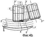
При многоосевой обработке, т.е. при обработке с изменяемой ориентацией оси инструмента, его ориентация на пути врезания следует за ориентацией инструмента в первой точке траектории, которая остается неизменной на всем пути врезания, как это видно на фиг.3а-3с, или ориентация инструмента следует за общей направляющей информацией о следующем обрабатываемом слое, как это видно на фиг.4а-4с.In multi-axis machining, i.e. when machining with a variable orientation of the axis of the tool, its orientation along the cutting path follows the orientation of the tool at the first point of the path, which remains unchanged along the entire cutting path, as can be seen in FIGS. 3a-3c, or the orientation of the tool follows the general guide information about the next the processed layer, as seen in figa-4C.
Врезающая способность фрезерного инструмента определяется помимо расположения и формы (заточка, высота) торцевых режущих кромок способностью отвода создаваемой фрезерным инструментом стружки. Поэтому хорошая врезающая способность связана с ослаблением поперечного сечения, что снижает способность к восприятию боковых сил и, тем самым, также достигаемую объемную производительность резания. Поэтому высокопроизводительные фрезерные инструменты, как правило, ограничены в своей врезающей способности очень плоскими углами врезания, что увеличивает дополнительные пути для достижения глубины обработки и, тем самым, время обработки. В частности, в случае небольших карманов и режущего не посередине фрезерного инструмента пути врезания требуемой длины часто не реализуются. Кроме того, в различных материалах врезание под очень плоским углом может привести к значительному износу фрезерного инструмента и, тем самым, к повышению его стоимости и снижению надежности процесса.The cutting ability of the milling tool is determined in addition to the location and shape (sharpening, height) of the end cutting edges by the ability to divert the chips created by the milling tool. Therefore, good cutting ability is associated with a weakening of the cross section, which reduces the ability to perceive lateral forces and, thus, also achieved volumetric cutting performance. Therefore, high-performance milling tools, as a rule, are limited in their cutting ability by very flat cutting angles, which increases the additional paths to achieve the processing depth and, thus, the processing time. In particular, in the case of small pockets and a cutting tool not in the middle of the milling tool, the cutting paths of the required length are often not realized. In addition, cutting in a very flat angle in various materials can lead to significant wear of the milling tool and, thereby, to increase its cost and reduce the reliability of the process.
Из ЕР 1034865 В1 известен способ фрезерования для изготовления турбинной лопатки из заготовки, при котором фрезерный инструмент направляется по непрерывной спиралеобразной направляющей траектории от внешнего контура заготовки к контуру готовой детали, причем при постоянном съеме материала достигается непрерывное изменение формы от заготовки к готовой детали. Во время фрезерования ось фрезерного инструмента может наклоняться на угол отклонения от вектора нормали в точке касания вперед в направлении направляющей траектории или опрокидываться на угол наклона от вектора нормали вбок.A milling method for manufacturing a turbine blade from a workpiece is known from EP 1034865 B1, in which the milling tool is guided along a continuous spiral-shaped guide path from the external contour of the workpiece to the contour of the finished part, and with constant material removal, a continuous change in shape from the workpiece to the finished part is achieved. During milling, the axis of the milling tool can be tilted by an angle of deviation from the normal vector at the point of contact forward in the direction of the guide path, or tilted by an angle of inclination from the normal vector sideways.
Из ЕР 1356886 А1 известен способ фрезерования глубоких каналов. При этом должно происходить щадящее инструмент и деталь исключительно попутное фрезерование без сплошного прохождения. Циклоидная траектория центра фрезы предусмотрена за счет наложения эксцентричной круговой траектории на поступательное движение продольной подачи. Для оптимального прилегания фрезерного инструмента к непараллельным боковым стенкам инструмент можно повернуть так, чтобы он был временно параллелен касательным к боковым стенкам.From EP 1356886 A1, a method for milling deep channels is known. In this case, a gentle tool and the part must exclusively be milled simultaneously without continuous passage. The cycloid path of the center of the cutter is provided by superimposing an eccentric circular path on the translational movement of the longitudinal feed. For optimal fit of the milling tool to non-parallel side walls, the tool can be rotated so that it is temporarily parallel tangent to the side walls.
В US-А-3811163 описана обработка карманов, причем хвостовые фрезы могут резать как торцевой стороной, так и боковой поверхностью. За сверлящей подачей на глубину следует боковая поперечная подача, которая из-за высокой изгибающей нагрузки составляет обычно не глубже 20% диаметра инструмента. Открытое резание расширяется вбок, прежде чем произойдет следующая подача на глубину, пока не будет достигнута общая поперечная подача от 1,5- до 2-кратного значения диаметра инструмента.In US-A-3811163, processing of pockets is described, wherein tail mills can be cut with both an end face and a side surface. A depth lateral feed follows a drilling feed to the depth, which, due to the high bending load, is usually not deeper than 20% of the tool diameter. Open cutting expands laterally before the next depth feed occurs until a total lateral feed of 1.5 to 2 times the diameter of the tool is achieved.
В основе изобретения лежит задача создания способа врезания фрезерного инструмента в удаляемый материал заготовки, который позволил бы предотвратить названные недостатки, использовать фрезерные инструменты более щадящим образом и повысить надежность процесса или, в частности, обеспечить надежную обработку трудно поддающихся резанию материалов, а также привел бы к значительному сокращению производственных расходов.The basis of the invention is the task of creating a method of cutting a milling tool into a removable workpiece material, which would prevent these drawbacks, use milling tools in a more gentle way and increase process reliability or, in particular, ensure reliable processing of materials that are difficult to cut, and also lead to a significant reduction in production costs.
Эта задача решается неожиданно простым образом посредством признаков п.1 формулы.This problem is solved in an unexpectedly simple way through the features of claim 1 of the formula.
За счет выполнения предложенного способа изготовления детали из заготовки посредством фрезерного инструмента, при котором фрезерный инструмент при врезании в материал заготовки по отношению к пути врезания с отклонением от ориентации фрезерного инструмента для непосредственно следующей за этим обработки автоматически поворачивается или опрокидывается или наклоняется в направлении продольной подачи и/или вбок относительно направления продольной подачи, можно полностью избежать или, по меньшей мере, в значительной мере уменьшить осевые нагрузки на фрезерный инструмент вследствие режима резания сверлением на пути врезания фрезерного инструмента в материал заготовки. Вместе с тем способ отличается особенно тем, что фрезерные инструменты используются в более щадящем режиме. Одновременно этим способом, в целом, существенно повышается надежность процесса и, в частности, обеспечивается надежная обработка трудно поддающихся резанию материалов. Наконец, способ позволяет значительно сократить производственные расходы.Due to the implementation of the proposed method for manufacturing a part from a workpiece by means of a milling tool, in which the milling tool when cutting into the workpiece material with respect to the cutting path deviates from the orientation of the milling tool for immediately following processing, it automatically turns or capsizes or tilts in the direction of longitudinal feed and / or sideways with respect to the direction of longitudinal feed, it is possible to completely avoid or at least significantly reduce the load on the milling tool due to the cutting mode by drilling on the path of cutting the milling tool into the workpiece material. However, the method is particularly distinguished by the fact that milling tools are used in a more gentle manner. At the same time, this method, in general, significantly increases the reliability of the process and, in particular, provides reliable processing of difficult to cut materials. Finally, the method can significantly reduce production costs.
Другие, особенно предпочтительные подробности способа описаны в п.п.2-15.Other, particularly preferred details of the method are described in claims 2-15.
Согласно признакам п.2, фрезерный инструмент направляется на пути врезания, который выполнен рампообразным.According to the characteristics of
В этой связи, согласно изобретению, предусмотрено, что фрезерный инструмент по п.3 направляется на пути врезания, выполненном в виде простой рампы.In this regard, according to the invention, it is provided that the milling tool according to
В альтернативном варианте фрезерный инструмент по п.4 может направляться на пути врезания, выполненном в виде сложной рампы, с направлением продольной подачи, изменяющимся возвратно-поступательно в форме зигзага, меандра или т.п.Alternatively, the milling tool according to
Далее в рамках изобретения фрезерный инструмент по п.5 направляется на пути врезания, выполненном спиральным, цилиндрическим, коническим или подобной формы.Further, within the framework of the invention, the milling tool according to
Преимущественно фрезерный инструмент по п.6 направляется на пути врезания, выполненном в форме спирали, по меньшей мере, с одним оборотом.Advantageously, the milling tool according to
Предпочтительным образом фрезерный инструмент по п.7 направляется на пути врезания, выполненном в форме частичной спирали (завитка).Preferably, the milling tool according to claim 7 is guided on a plunge path made in the form of a partial spiral (curl).
Согласно мерам по п.8, фрезерный инструмент направляется на пути врезания, выполненном в форме частичной спирали, причем подача на глубину осуществляется в форме меандра в несколько заходов (подач) с изменяющимся направлением продольной подачи.According to the measures of claim 8, the milling tool is guided on the cutting path made in the form of a partial spiral, and the depth feed is in the form of a meander in several passes (feeds) with a changing direction of the longitudinal feed.
Фрезерный инструмент по п.9 направляется на пути врезания, выполненном линейным и/или круговым.The milling tool according to claim 9 is guided on a plunge path made linear and / or circular.
В качестве альтернативы или дополнительно фрезерный инструмент в соответствии с признаками п.10 направляется на пути врезания, выполненном в виде сплайна или непрерывно-искривленной кривой.Alternatively or additionally, the milling tool, in accordance with the features of clause 10, is guided along the plunge path made in the form of a spline or a continuously curved curve.
Особое преимущество имеют меры по п.11, в соответствии с которыми путь врезания фрезерного инструмента определяется круговой интерполяцией при подаче на глубину.The measures according to claim 11 have a particular advantage, according to which the cutting path of the milling tool is determined by circular interpolation when applied to a depth.
Кроме того, в рамках изобретения путь врезания фрезерного инструмента по п.12 определяется посредством непрерывно-искривленной интерполяции при подаче на глубину.In addition, within the framework of the invention, the insertion path of the milling tool according to claim 12 is determined by continuously curved interpolation when applied to a depth.
Целесообразно путь врезания фрезерного инструмента по п.13 складывается из отрезков с линейно и/или кругообразно и/или непрерывно-искривленно интерполированной подачей на глубину.The insertion path of the milling tool according to claim 13 is expediently composed of segments with linearly and / or circularly and / or continuously-curved interpolated depth feed.
Далее особенно предпочтительно, что путь врезания фрезерного инструмента по п.14 задается посредством отличающейся от пути обработки скорости продольной подачи.It is further particularly preferred that the insertion path of the milling tool according to claim 14 is defined by means of a longitudinal feed rate different from the processing path.
Наконец, согласно изобретению, преимущественно еще предусмотрено, что угол опрокидывания фрезерного инструмента по п.15 больше угла наклона рампообразного пути врезания. В принципе, для предотвращения или уменьшения условий резания сверлением желателен угол опрокидывания фрезерного инструмента, который больше угла наклона рампообразного пути врезания. Во избежание возможных столкновений фрезерный инструмент опрокидывается преимущественно вбок относительно направления движения. Если же таким образом нельзя избежать столкновений, то целесообразным или даже необходимым может быть также меньший угол опережения для уменьшения условий резания сверлением.Finally, according to the invention, it is advantageously further provided that the tilting angle of the milling tool according to claim 15 is greater than the inclination angle of the ramp-shaped cutting path. In principle, in order to prevent or reduce cutting conditions by drilling, a tipping angle of the milling tool, which is greater than the angle of inclination of the ramp-shaped cutting path, is desirable. To avoid possible collisions, the milling tool tilts mainly to the side relative to the direction of travel. If collisions cannot be avoided in this way, then a smaller lead angle may also be appropriate or even necessary to reduce cutting conditions by drilling.
Другие признаки, преимущества и подробности изобретения приведены в нижеследующем описании некоторых предпочтительных вариантов его осуществления и на чертежах, на которых изображают:Other features, advantages, and details of the invention are set forth in the following description of some preferred embodiments thereof and in the drawings, in which:
- фиг.1а: схематичный вид фрезерного инструмента для пояснения заявленного способа изготовления детали из заготовки посредством фрезерного инструмента, причем последний рампообразно врезается в материал заготовки в соответствии с фиг.2а;- figa: a schematic view of a milling tool to explain the claimed method of manufacturing a part from a workpiece using a milling tool, the latter being rammed into the workpiece material in accordance with figa;
- фиг.1b: схематичный вид фрезерного инструмента для пояснения заявленного способа, причем фрезерный инструмент врезается в материал заготовки в соответствии с фиг.1а рампообразно с круговой интерполяцией подачи на глубину;- fig.1b: a schematic view of a milling tool to explain the claimed method, and the milling tool cuts into the workpiece in accordance with figa ramp with circular interpolation of the feed to the depth;
- фиг.1с: схематичный вид фрезерного инструмента для пояснения заявленного способа, причем фрезерный инструмент врезается в материал заготовки в соответствии с фиг.1b рампообразно с круговой интерполяцией подачи на глубину в несколько заходов и с переменным направлением продольной подачи, причем отдельные подачи на глубину связаны с плавным движением для переориентации фрезерного инструмента;- figs: a schematic view of a milling tool to explain the claimed method, and the milling tool cuts into the workpiece in accordance with fig.1b ramp with circular interpolation of the feed to a depth of several runs and with a variable direction of longitudinal feed, with individual feeds to the depth connected with smooth movement for reorientation of the milling tool;
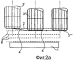
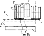
- фиг.2а, 2b, 2с: схематичные виды фрезерного инструмента для пояснения известных способов трехосевой обработки, причем фрезерный инструмент врезается в материал заготовки различным образом;- figa, 2b, 2C: schematic views of a milling tool to explain the known methods of triaxial processing, and the milling tool cuts into the workpiece material in various ways;
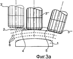
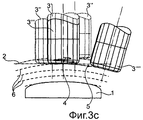
- фиг.3а, 3b, 3с: схематичные виды фрезерного инструмента для пояснения известных способов многоосевой обработки или обработки с изменяемой ориентацией оси инструмента, причем фрезерный инструмент врезается в материал заготовки различным образом, и во время врезания ориентация фрезерного инструмента неизменно соответствует ориентации фрезерного инструмента в первом положении после достижения полной глубины поперечной подачи;- figa, 3b, 3c: schematic views of a milling tool for explaining known methods of multi-axis machining or machining with a variable orientation of the tool axis, and the milling tool cuts into the workpiece in various ways, and during cutting the orientation of the milling tool invariably corresponds to the orientation of the milling tool in the first position after reaching the full depth of the transverse feed;
- фиг.4а, 4b, 4с: схематичные виды фрезерного инструмента для пояснения других известных способов многоосевой обработки или обработки с изменяемой ориентацией оси инструмента, причем фрезерный инструмент врезается в материал заготовки различным образом и во время врезания следует общим правилам ориентации инструмента.- figa, 4b, 4c: schematic views of a milling tool for explaining other known methods of multi-axis machining or machining with a variable orientation of the tool axis, and the milling tool cuts into the workpiece in various ways and during insertion follows the general rules of tool orientation.
В нижеследующем описании различных вариантов заявленного способа изготовления детали 1 из заготовки 2 посредством фрезерного инструмента 3 соответствующие друг другу, одинаковые конструктивные элементы обозначены одинаковыми ссылочными позициями.In the following description of the various variants of the claimed method of manufacturing parts 1 from the
При этом фрезерный инструмент 3' находится в начале пути врезания, фрезерный инструмент 3'' - на пути врезания, фрезерный инструмент 3''' - в конце пути врезания, соответственно, в начале следующей обработки, а фрезерный инструмент 3'''' - во время следующей обработки.In this case, the milling tool 3 'is at the beginning of the plunge path, the milling tool 3' 'is on the plunge path, the milling tool 3' '' is at the end of the plunge path, respectively, at the beginning of the next processing, and the milling tool 3 '' '' is during the next treatment.
Путь врезания фрезерного инструмента 3, т.е. путь инструмента во время врезания, обозначен поз.4, а путь обработки фрезерным инструментом 3, т.е. путь фрезерного инструмента во время обработки, - поз.5. Поз.6 обозначены различные подачи на глубину обработки.The cutting path of the
На фиг.1а-1с схематично изображен заявленный способ, при котором врезание фрезерного инструмента, соответственно, фрезы 3 в материал происходит при многоосевой обработке, соответственно, обработке с изменяемой ориентацией оси инструмента, согласно объекту изобретения, на примере рампообразной подачи на глубину. В отличие от общих правил ориентации фрезерного инструмента 3 при обработке каждого слоя ориентация инструмента во время врезания следует заданным условиям для предотвращения резания сверлением - здесь в виде угла опережения по отношению к траектории.On figa-1c schematically shows the claimed method, in which the cutting of the milling tool, respectively, of the
Этим предотвращаются, по меньшей мере, значительно уменьшаются режимы резания сверлением.This prevents, at least, significantly reduced cutting conditions by drilling.
Форма траектории и ориентация инструмента оптимизируются, тем самым, для пути врезания отдельно в отношении особых режимов резания на этом отрезке, чтобы избежать недостатков способов из уровня техники.The shape of the path and the orientation of the tool are optimized, thereby, for the cutting path separately in relation to the special cutting conditions on this segment, in order to avoid the disadvantages of the methods of the prior art.
В простейшем случае, как это видно на фиг.1а, 1b, фрезерный инструмент 3 автоматически в соответствии с углом рампообразного пути 4 врезания опрокидывается в направлении продольной подачи, причем угол опрокидывания фрезерного инструмента 3 должен быть больше угла наклона рампообразного пути 4 врезания. Во избежание возможных столкновений фрезерный инструмент 3 опрокидывается преимущественно вбок относительно направления движения. По достижении глубины обработки или конца пути 4 врезания устанавливается ориентация фрезерного инструмента 3, которая задана посредством общей управляющей информации для обработки.In the simplest case, as can be seen in FIGS. 1a, 1b, the
Если подача на глубину на фиг.1с происходит в несколько заходов с изменяющимся направлением продольной подачи, то путь 4 врезания при каждой смене направления продольной подачи характеризуется областью, в которой фрезерный инструмент 3 переориентируется в отношении угла опережения, причем в точке касания фрезерного инструмента подачи на глубину не происходит. При этом опционально может также произойти изменение бокового наклона.If the depth feed in Fig. 1c occurs in several passes with a changing direction of the longitudinal feed, then the cutting
В случае рампы или спирали с линейной интерполяцией подачи на глубину угол опрокидывания фрезерного инструмента 3 в направлении продольной подачи на пути врезания 4 постоянный по отношению к осям станка.In the case of a ramp or spiral with linear interpolation of the depth feed, the tipping angle of the
Если путь 4 врезания представляет собой круговой сегмент (фиг.1b), соответственно, непрерывно-искривленную кривую или комбинированный путь 4 врезания содержит такие участки, то из касательной к пути 4 врезания возникает требуемый угол опрокидывания. Таким образом, угол опрокидывания фрезерного инструмента 3 в направлении продольной подачи на пути 4 врезания непостоянный по отношению к осям станка. Во избежание резких движений осей станка следует избегать малых радиусов для пути 4 врезания.If the
На фиг.2а-2с схематично изображены различные известные способы фрезерования с режимами врезания для трехосевой обработки. Ориентация фрезерного инструмента 3 остается неизменной. Проходимый путь возникает из максимально допустимого угла фрезерного инструмента 3 и достигаемой глубины. Хорошо видно, что фрезерный инструмент 3 во время подачи на глубину своей торцевой стороной врезается в материал заготовки 2. Пути подвода и отвода «прицепляются», как правило, дополнительно к вычисленной траектории обработки фрезерным инструментом.On figa-2C schematically shows various known methods of milling with cutting modes for triaxial processing. The orientation of the
На фиг.2а изображено рампообразное врезание в материал заготовки 2 в виде непрерывного продолжения последующей траектории обработки. Этим можно избежать кратковременной остановки фрезерного инструмента 3.On figa shows a ram-shaped incision into the material of the
На фиг.2b изображен вариант рампообразного врезания в материал заготовки, когда для врезания фрезерного инструмента 3 на фиг.2а не хватает достаточной длины пути. Врезание на глубину происходит тогда с более частой сменой движений, сопоставимо с зигзагом.Figure 2b shows a variant of ramp-shaped cutting into the workpiece material when a sufficient path length is not enough for cutting the
На фиг.2с изображено спиральное врезание фрезерного инструмента 3 в материал заготовки 2. Число оборотов помимо достигаемой глубины и максимально допустимого угла врезания определяется также радиусом спирали.Fig. 2c shows a spiral insertion of a
На фиг.3а-3с схематично изображено врезание фрезерного инструмента 3 в материал заготовки 2 при многоосевой обработке, т.е. при обработке с изменяемой ориентацией оси инструмента в соответствии с уровнем техники, причем ориентация фрезерного инструмента в первой точке траектории подлежащей достижению глубины для всей подачи на глубину сохраняется неизменной. Такое направление движения типично для обработки, при которой ориентация инструмента определяется векторами нормалей к поверхностям. При такой многоосевой обработке часто на пути 4 врезания ориентация фрезерного инструмента 3 в первой точке траектории соответствующей глубины обработки поддерживается неизменной на всем пути 4 врезания. На фиг.3а-3с видно, что при этом могут возникнуть условия резания сверлением.Figures 3a-3c schematically depict the insertion of a
На фиг.3а изображена ориентация инструмента при рампообразном врезании в материал заготовки 2 в виде непрерывного продолжения последующей траектории обработки.On figa shows the orientation of the tool during ram-shaped cutting into the material of the
На фиг.3b изображена ориентация инструмента при рампообразном врезании в материал заготовки 2, когда для врезания фрезерного инструмента 3 на фиг.2а не хватает достаточной длины пути.Fig. 3b shows the orientation of the tool during ram-shaped cutting into the material of the
На фиг.3с изображена ориентация инструмента при спиральном врезании.On figs shows the orientation of the tool with spiral cutting.
На фиг.4а-4с схематично изображено врезание фрезы 3 в материал заготовки 2 при многоосевой обработке или обработке с изменяемой ориентацией оси инструмента в соответствии с уровнем техники, причем ориентация инструмента непрерывно продолжается в соответствии с общими определенными правилами. Это направление движения типично для обработки, при которой ориентация инструмента определяется кривыми, точками или общими правилами предотвращения столкновений. При такой многоосевой обработке для ориентации фрезерного инструмента 3 применяется также общая управляющая информация о последующей обработке, соответственно, этапе обработки, которая ориентируется на режим резания во время собственно обработки и предотвращения столкновений. Как видно на примерах на фиг.4а-4с, также здесь во время врезания могут возникнуть режимы резания сверлением.Figures 4a-4c schematically depict the insertion of a
На фиг.4а изображена ориентация инструмента при рампообразном врезании в материал в виде непрерывного продолжения последующей траектории обработки.On figa shows the orientation of the tool with ram-shaped incision into the material in the form of a continuous continuation of the subsequent processing path.
На фиг.4b изображена ориентация инструмента при рампообразном врезании в материал, когда для врезания фрезерного инструмента на фиг.2а не хватает достаточной длины пути.Fig. 4b shows the orientation of the tool during ram-shaped cutting into the material, when a sufficient path length is not enough for cutting the milling tool in Fig. 2a.
На фиг.4с изображена ориентация инструмента при спиральном врезании в материал.On figs shows the orientation of the tool with a spiral cutting into the material.
Claims (25)
Applications Claiming Priority (2)
| Application Number | Priority Date | Filing Date | Title |
|---|---|---|---|
| DE102008033130A DE102008033130B3 (en) | 2008-07-15 | 2008-07-15 | Method for producing a finished part from a blank by means of a milling tool |
| DE102008033130.9 | 2008-07-15 |
Publications (2)
| Publication Number | Publication Date |
|---|---|
| RU2011105412A RU2011105412A (en) | 2012-08-20 |
| RU2465103C2 true RU2465103C2 (en) | 2012-10-27 |
Family
ID=41259719
Family Applications (1)
| Application Number | Title | Priority Date | Filing Date |
|---|---|---|---|
| RU2011105412/02A RU2465103C2 (en) | 2008-07-15 | 2009-07-14 | Method of making part from blank by hobbing |
Country Status (9)
| Country | Link |
|---|---|
| US (1) | US20110188959A1 (en) |
| EP (1) | EP2282861B1 (en) |
| JP (1) | JP5389913B2 (en) |
| KR (1) | KR101272652B1 (en) |
| CN (1) | CN102137729B (en) |
| AT (1) | ATE546249T1 (en) |
| DE (1) | DE102008033130B3 (en) |
| RU (1) | RU2465103C2 (en) |
| WO (1) | WO2010006768A1 (en) |
Families Citing this family (11)
| Publication number | Priority date | Publication date | Assignee | Title |
|---|---|---|---|---|
| CN102350522B (en) * | 2011-06-30 | 2013-02-20 | 西北工业大学 | Processing method of numerical control milling machine with tiltable main shaft |
| DE102012016676B4 (en) * | 2012-08-23 | 2016-02-11 | ModuleWorks GmbH | Method for roughing a workpiece with a multi-axis milling machine |
| CN103949701B (en) * | 2014-04-08 | 2016-04-20 | 西安理工大学 | Based on the irregular part milling method of rotating vector |
| JP5855715B1 (en) * | 2014-08-07 | 2016-02-09 | ファナック株式会社 | Machine Tools |
| WO2016051342A1 (en) * | 2014-10-02 | 2016-04-07 | Frangi Lorenzo | Machine tool |
| TWI568528B (en) | 2014-11-06 | 2017-02-01 | 財團法人工業技術研究院 | Cutting tool controller and controlling method thereof |
| DE102015104679C5 (en) * | 2015-03-26 | 2023-09-07 | Open Mind Technologies Ag | Process for removing material from flat surfaces of a workpiece |
| TWI587950B (en) * | 2015-04-10 | 2017-06-21 | Hsin Tien Chang | Butterfly milling method |
| JP2017068586A (en) * | 2015-09-30 | 2017-04-06 | ファナック株式会社 | Numerical control apparatus which controls position of collision between tool cutter tip and work material |
| DE102016117932B4 (en) * | 2016-09-22 | 2020-06-10 | Open Mind Technologies Ag | Process for the removal of material from rounding surfaces of a workpiece |
| CN114799293B (en) * | 2022-06-30 | 2023-03-21 | 中国空气动力研究与发展中心高速空气动力研究所 | Machining method for wind tunnel complex curved surface contraction section |
Citations (4)
| Publication number | Priority date | Publication date | Assignee | Title |
|---|---|---|---|---|
| SU1720809A1 (en) * | 1986-09-30 | 1992-03-23 | Научно-производственное объединение "Оптика" | Method for machining curvilinear grooves |
| DE19903216A1 (en) * | 1998-01-27 | 1999-08-05 | Toshiba Machine Co Ltd | Control system for milling process |
| EP1356889A1 (en) * | 2002-04-24 | 2003-10-29 | Mechafin AG | Welding wire feeding device comprising at least two rollers driven by a worm gear |
| RU2238182C2 (en) * | 1998-12-11 | 2004-10-20 | Эрвин Юнкер Машиненфабрик Гмбх | Method for controlling process for in-feed grinding of blank and machine tool for performing the same |
Family Cites Families (23)
| Publication number | Priority date | Publication date | Assignee | Title |
|---|---|---|---|---|
| US3811163A (en) * | 1972-12-07 | 1974-05-21 | Gen Dynamics Corp | Plunge milling tool |
| US4534743A (en) * | 1983-08-31 | 1985-08-13 | Timex Corporation | Process for making an electroluminescent lamp |
| JPS62176709A (en) * | 1986-01-28 | 1987-08-03 | Toyota Central Res & Dev Lab Inc | Method and tool for working curved surface |
| JPH0366513A (en) * | 1989-08-02 | 1991-03-22 | Hitachi Seiki Co Ltd | Slitting method for pocket working |
| JPH07227709A (en) * | 1994-02-16 | 1995-08-29 | Toyota Motor Corp | Cutting device |
| CN1102890A (en) * | 1994-07-02 | 1995-05-24 | 华中理工大学 | CNC system of directly interpolation of curved surface profile |
| JPH0994732A (en) * | 1995-09-29 | 1997-04-08 | Hitachi Seiko Ltd | Processing method for two-dimensional shape |
| JPH11114772A (en) * | 1997-10-07 | 1999-04-27 | Shin Nippon Koki Co Ltd | Free curved surface machining method |
| JPH11114716A (en) * | 1997-10-20 | 1999-04-27 | Mazda Motor Corp | Machining method of die |
| US6311100B1 (en) * | 1998-09-14 | 2001-10-30 | Mass. Institute Of Technology | Tool path generator for computer aided manufacturing |
| US6077002A (en) * | 1998-10-05 | 2000-06-20 | General Electric Company | Step milling process |
| DE19846426A1 (en) * | 1998-10-08 | 2000-04-13 | Open Mind Software Technologie | Multi axis machining center with independent control of the axes of the cutting tool |
| JP2000233310A (en) * | 1999-02-17 | 2000-08-29 | Toshiba Corp | Cutting method |
| DE59900206C5 (en) * | 1999-03-08 | 2010-09-09 | Alstom (Schweiz) Ag, Baden | milling |
| DE10031441B4 (en) * | 2000-06-28 | 2006-10-12 | Open Mind Technologies Ag | Method for controlling the working movement of a milling tool |
| JP4068321B2 (en) * | 2001-09-27 | 2008-03-26 | 株式会社ジェイテクト | Processing speed setting method and processing apparatus of processing apparatus |
| DE10219012B4 (en) * | 2002-04-27 | 2004-11-04 | Mtu Aero Engines Gmbh | milling |
| EP1590712B1 (en) * | 2003-01-29 | 2011-03-02 | OPEN MIND Technologies AG | Method for controlling relative displacements of a tool against a workpiece |
| DE10322340B4 (en) * | 2003-05-17 | 2006-09-14 | Mtu Aero Engines Gmbh | Method and device for milling free-form surfaces |
| JP2004362270A (en) * | 2003-06-04 | 2004-12-24 | Nissan Motor Co Ltd | Swing angle setting device and method for cutting tool and swing angle setting program for cutting tool |
| DE10330831A1 (en) * | 2003-07-08 | 2005-02-10 | Mtu Aero Engines Gmbh | Milling process for the production of components |
| JP2005096399A (en) * | 2003-09-02 | 2005-04-14 | Tokyo Denki Univ | Ball end mill working method and square end mill working method |
| DE102005001600B4 (en) * | 2004-11-30 | 2011-08-18 | FOLLOW ME! Technology Systems GmbH, 81675 | Method for material-removing machining of workpieces and workpiece or molding element |
-
2008
- 2008-07-15 DE DE102008033130A patent/DE102008033130B3/en active Active
-
2009
- 2009-07-14 AT AT09777187T patent/ATE546249T1/en active
- 2009-07-14 JP JP2011517804A patent/JP5389913B2/en active Active
- 2009-07-14 RU RU2011105412/02A patent/RU2465103C2/en not_active IP Right Cessation
- 2009-07-14 CN CN200980133333.9A patent/CN102137729B/en active Active
- 2009-07-14 US US13/054,535 patent/US20110188959A1/en not_active Abandoned
- 2009-07-14 KR KR1020117002938A patent/KR101272652B1/en active IP Right Grant
- 2009-07-14 WO PCT/EP2009/005118 patent/WO2010006768A1/en active Application Filing
- 2009-07-14 EP EP09777187A patent/EP2282861B1/en not_active Revoked
Patent Citations (4)
| Publication number | Priority date | Publication date | Assignee | Title |
|---|---|---|---|---|
| SU1720809A1 (en) * | 1986-09-30 | 1992-03-23 | Научно-производственное объединение "Оптика" | Method for machining curvilinear grooves |
| DE19903216A1 (en) * | 1998-01-27 | 1999-08-05 | Toshiba Machine Co Ltd | Control system for milling process |
| RU2238182C2 (en) * | 1998-12-11 | 2004-10-20 | Эрвин Юнкер Машиненфабрик Гмбх | Method for controlling process for in-feed grinding of blank and machine tool for performing the same |
| EP1356889A1 (en) * | 2002-04-24 | 2003-10-29 | Mechafin AG | Welding wire feeding device comprising at least two rollers driven by a worm gear |
Also Published As
| Publication number | Publication date |
|---|---|
| EP2282861B1 (en) | 2012-02-22 |
| RU2011105412A (en) | 2012-08-20 |
| DE102008033130B3 (en) | 2010-02-11 |
| JP2011527949A (en) | 2011-11-10 |
| ATE546249T1 (en) | 2012-03-15 |
| JP5389913B2 (en) | 2014-01-15 |
| EP2282861A1 (en) | 2011-02-16 |
| KR101272652B1 (en) | 2013-06-11 |
| US20110188959A1 (en) | 2011-08-04 |
| KR20110044220A (en) | 2011-04-28 |
| CN102137729A (en) | 2011-07-27 |
| CN102137729B (en) | 2014-12-24 |
| WO2010006768A1 (en) | 2010-01-21 |
Similar Documents
| Publication | Publication Date | Title |
|---|---|---|
| RU2465103C2 (en) | Method of making part from blank by hobbing | |
| US9696707B2 (en) | Method of controlling tool orientation and step-over distance in face milling of curvilinear surfaces | |
| JP2000263309A (en) | Milling method | |
| US8992144B2 (en) | Method for producing conical or hypoid wheels using the plunging process | |
| RU2358843C2 (en) | Milling method | |
| WO2008090301A1 (en) | Milling cutter manufacturing method | |
| EP3208023B1 (en) | Convex gear tooth edge | |
| US20200016669A1 (en) | Method for material-removing machining of fillets on a workpiece | |
| JP6858407B2 (en) | Double-threaded body manufacturing method, double-threaded body manufacturing program | |
| CN102791410A (en) | Method for hard fine machining of the flanks of a gear wheel | |
| CA3033782C (en) | Deburring tool for deburring transverse recesses that branch from a main borehole | |
| KR20180059458A (en) | Finishing tools, especially end milling cutters | |
| DE102016102651A1 (en) | Apparatus and method for machining a rotating workpiece | |
| JP2004074394A5 (en) | Radius end mill and manufacturing method of forging die | |
| KR20220148166A (en) | A method for machining a toothed flank region of a workpiece toothed arrangement, a chamfering tool, a control program having control instructions for performing the method, and a gear cutting machine | |
| JPH0655304A (en) | Method and device for manufacturing work having recess part around its peripheral surface | |
| JP3689367B2 (en) | Hob cutter and face gear forming method | |
| JP6704204B2 (en) | Cutting method | |
| US20230064805A1 (en) | Method for producing a workpiece, in particular a turbine blade, using a milling tool | |
| WO2021172065A1 (en) | Processing method, processing device, processing program, and end mill | |
| CN113000948B (en) | Method for finishing a workpiece having teeth | |
| RU2422251C2 (en) | Method of milling complex surfaces | |
| JPS6254659A (en) | Chip receiving-groove machinging device for circumferential cutting tool with hemispherical end section | |
| KR20240026225A (en) | Deburring tool with a deburring blade for deburring the edges of holes | |
| KR20240011689A (en) | A method for machining a tooth flank region of a workpiece tooth arrangement, a chamfering tool, a control program having control instructions for performing the method, and a gear cutting machine. |
Legal Events
| Date | Code | Title | Description |
|---|---|---|---|
| MM4A | The patent is invalid due to non-payment of fees |
Effective date: 20200715 |