RU2463680C2 - Breaker with short circuit fault self-blocking function - Google Patents
Breaker with short circuit fault self-blocking function Download PDFInfo
- Publication number
- RU2463680C2 RU2463680C2 RU2010134566/07A RU2010134566A RU2463680C2 RU 2463680 C2 RU2463680 C2 RU 2463680C2 RU 2010134566/07 A RU2010134566/07 A RU 2010134566/07A RU 2010134566 A RU2010134566 A RU 2010134566A RU 2463680 C2 RU2463680 C2 RU 2463680C2
- Authority
- RU
- Russia
- Prior art keywords
- button
- electromagnet
- circuit breaker
- circuit
- self
- Prior art date
Links
Images


Landscapes
- Breakers (AREA)
Abstract
Description
Область техникиTechnical field
Настоящее изобретение относится к низковольтному электрическому прибору, а именно к размыкателю цепи с функцией самоблокировки короткого замыкания.The present invention relates to a low voltage electrical device, namely to a circuit breaker with a self-locking function of a short circuit.
Предшествующий уровень техникиState of the art
Предшествующий размыкатель цепи, также называемый воздушным выключателем, содержит, главным образом, корпус, ручку, перемычку самоблокировки, рычажный механизм размыкания, подвижный нож и подвижный контакт (см. фиг.1). Принцип его работы описан далее. Ручка управляется так, чтобы воздействовать на перемычку самоблокировки, и вследствие этого подвижный нож движется так, что его подвижный контакт примыкает к выходной металлической пластине, тем самым замыкая цепь. В то же время, перемычка самоблокировки зацепляется с размыкающим механизмом для обеспечения самоблокировки в рабочем состоянии (см. фиг.2). Для защиты цепи, предшествующий размыкатель цепи также имеет механизм активации при коротком замыкания с защитной биметаллической пластиной. Когда величина тока, протекающего в размыкателе цепи, становится выше установленной, обычно в десять раз больше установленной, которая вызывает короткое замыкание, катушка перегрузки механизма активации при коротком замыкании вызывает движение сердечника механизма активации при коротком замыкании, который нажимает на нижний конец рычажного механизма размыкания, вызывающего поворот рычажного механизма размыкания таким образом, что перемычка самоблокировки отсоединяется от рычажного механизма размыкания, тем самым размыкая цепь и обеспечивая защиту. Принцип работы биметаллической пластины является следующим. Когда величина тока, протекающего в размыкателе цепи, становится выше установленной, обычно в два раза превышающей установленную, биметаллическая пластина отклоняется и поворачивает рычажный механизм размыкания таким образом, что перемычка самоблокировки отсоединяется от размыкающего механизма, тем самым размыкая цепь и обеспечивая защиту. Тем не менее, сердечник механизма активации при коротком замыкании и биметаллическая пластина возвращаются в их исходное положение после срабатывания размыкателя цепи. Вышеупомянутый размыкатель цепи может защищать цепь от короткого замыкания, но он имеет недостаток, заключающийся в том, что размыкатель цепи может быть снова замкнут без определения причины, по которой размыкатель цепи был разомкнут, и оператор не знает, была ли причиной защита от перегрузки или защита при коротком замыкании, так что аварийная ситуация может повториться опять, перегружая электросеть или вызывая возгорание. Подобные аварии могут повторяться много раз.The preceding circuit breaker, also called an air circuit breaker, mainly comprises a housing, a handle, a self-locking jumper, a lever opening mechanism, a movable knife and a movable contact (see FIG. 1). The principle of its operation is described below. The handle is controlled so as to act on the self-locking jumper, and as a result, the movable knife moves so that its movable contact adjoins the output metal plate, thereby closing the chain. At the same time, the self-locking jumper engages with the disconnecting mechanism to ensure self-locking in working condition (see figure 2). To protect the circuit, the preceding circuit breaker also has a short-circuit activation mechanism with a protective bimetal plate. When the amount of current flowing in the circuit breaker becomes higher than the set, usually ten times larger than the set, which causes a short circuit, the overload coil of the activation mechanism during short circuit causes the core of the activation mechanism to move during short circuit, which presses on the lower end of the lever circuit breaker, causing the lever opening mechanism to rotate in such a way that the self-locking jumper is disconnected from the lever opening mechanism, thereby opening the circuit and providing protection. The principle of operation of the bimetallic plate is as follows. When the amount of current flowing in the circuit breaker becomes higher than the set value, usually two times higher than the set value, the bimetallic plate is deflected and rotates the release mechanism so that the self-locking jumper is disconnected from the release mechanism, thereby opening the circuit and providing protection. However, the core of the activation mechanism in the event of a short circuit and the bimetallic plate return to their original position after the circuit breaker operates. The aforementioned circuit breaker can protect the circuit from short circuit, but it has the disadvantage that the circuit breaker can be closed again without determining the reason why the circuit breaker was opened, and the operator does not know whether the overload protection or the protection was the cause in the event of a short circuit, so that the emergency can happen again, overloading the power supply or causing a fire. Such accidents can be repeated many times.
Раскрытие изобретенияDisclosure of invention
Цель настоящего изобретения - обеспечение размыкателя цепи с функцией самоблокировки короткого замыкания, который не может быть повторно замкнут до тех пор, пока не будет возвращен в исходное состояние после блокировки цепи при коротком замыкании для уведомления пользователя о появлении короткого замыкания, тем самым преодолевая недостатки предшествующего уровня, связанные с возможностью дальнейшего повторения аварии, перегрузки электросети или возгорания.The purpose of the present invention is the provision of a circuit breaker with a self-locking function of a short circuit, which cannot be re-closed until it is returned to its original state after blocking a short circuit to notify the user of a short circuit, thereby overcoming the disadvantages of the prior art related to the possibility of further recurrence of the accident, overload of the mains or fire.
Для достижения вышеуказанной цели, по настоящему изобретению имеется механизм самоблокировки при коротком замыкании, обеспеченный в размыкателе цепи.To achieve the above objective, the present invention has a short-circuit self-locking mechanism provided in a circuit breaker.
Механизм самоблокировки при коротком замыкании включает узел самоблокировки, выполненный для удержания рычажного механизма размыкания в положении защиты при коротком замыкании, и узел восстановления, выполненный для воздействия на рычажный механизм размыкания и возвращения его в исходное положение.The short-circuit self-locking mechanism includes a self-locking unit made to hold the lever opening mechanism in the short-circuit protection position and a recovery unit made to act on the lever opening mechanism and return it to its original position.
Механизм самоблокировки при коротком замыкании включает узел самоблокировки, выполненный с возможностью воздействия сердечника механизма активации при коротком замыкания и его удержания для нажатия на рычажный механизм размыкания, и узел восстановления, выполненный с возможностью воздействия на сердечник механизма активации при коротком замыкании для возвращения его в исходное положение.The short-circuit self-locking mechanism includes a self-locking unit configured to expose the core of the activation mechanism during short circuit and hold it for pressing the lever opening mechanism, and a recovery unit configured to impact the core of the activation mechanism during short circuit to return it to its original position .
Поскольку размыкатель цепи по настоящему изобретению обеспечивается механизмом самоблокировки при коротком замыкании, то размыкатель цепи не может быть замкнут непосредственно после блокировки размыкателя цепи при коротком замыкании, за счет чего пользователь будет уведомлен о случае короткого замыкания и о том, что размыкатель цепи должен быть замкнут после выявления и устранения причины короткого замыкания. Настоящее изобретение не только поддерживает все функции обычного размыкателя цепи, но также обеспечивает функцию самоблокировки короткого замыкания, таким образом преодолевая недостатки предшествующего уровня, связанные с повреждением или возгоранием размыкателя цепи при его повторном замыкании после случая короткого замыкания.Since the circuit breaker of the present invention is provided with a self-locking mechanism during a short circuit, the circuit breaker cannot be closed immediately after the circuit breaker is locked during a short circuit, due to which the user will be notified of a short circuit and that the circuit breaker must be closed after identify and eliminate the causes of short circuits. The present invention not only supports all the functions of a conventional circuit breaker, but also provides a self-locking short circuit function, thereby overcoming the disadvantages of the prior art associated with damage or fire of a circuit breaker when it is short-circuited after a short circuit event.
Краткое описание чертежейBrief Description of the Drawings
Фиг.1 - схематичный вид, иллюстрирующий обычный размыкатель цепи в разомкнутом положении.Figure 1 is a schematic view illustrating a conventional circuit breaker in the open position.
Фиг.2 - схематичный вид, иллюстрирующий обычный размыкатель цепи в замкнутом положении.Figure 2 is a schematic view illustrating a conventional circuit breaker in the closed position.
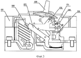
Фиг.3 - схематичный вид, иллюстрирующий обычный трехфазный автоматический выключатель в литом корпусе в разомкнутом положении.Figure 3 is a schematic view illustrating a conventional three-phase molded case circuit breaker in an open position.
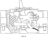
Фиг.4 - схематичный вид, иллюстрирующий обычный трехфазный автоматический выключатель в литом корпусе в замкнутом положении.4 is a schematic view illustrating a conventional three-phase molded case circuit breaker in a closed position.
Фиг.5 - схематичный вид, иллюстрирующий вариант осуществления 1 по настоящему изобретению для замкнутого положения.5 is a schematic view illustrating an
Фиг.6 - схематичный вид, иллюстрирующий вариант осуществления 1 по настоящему изобретению для положения самоблокировки.6 is a schematic view illustrating an
Фиг.7 - схематичный вид, иллюстрирующий вариант осуществления 2 по настоящему изобретению для замкнутого положения.7 is a schematic view illustrating an embodiment 2 of the present invention for a closed position.
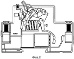
Фиг.8 - схематичный вид, иллюстрирующий вариант осуществления 2 по настоящему изобретению для положения самоблокировки.8 is a schematic view illustrating an embodiment 2 of the present invention for a self-locking position.
Фиг.9 - схематичный вид, иллюстрирующий вариант осуществления 3 по настоящему изобретению для замкнутого положения.9 is a schematic view illustrating an embodiment 3 of the present invention for a closed position.
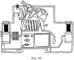
Фиг.10 - схематичный вид, иллюстрирующий вариант осуществления 3 по настоящему изобретению для положения самоблокировки.10 is a schematic view illustrating an embodiment 3 of the present invention for a self-locking position.
Фиг.11 - схематичный вид, иллюстрирующий вариант осуществления 4 по настоящему изобретению для замкнутого положения.11 is a schematic view illustrating an embodiment 4 of the present invention for a closed position.
Фиг.12 - схематичный вид, иллюстрирующий вариант осуществления 4 по настоящему изобретению для положения самоблокировки.12 is a schematic view illustrating an embodiment 4 of the present invention for a self-locking position.
Фиг.13 - схематичный вид, иллюстрирующий вариант осуществления 5 по настоящему изобретению для замкнутого положения.13 is a schematic view illustrating an embodiment 5 of the present invention for a closed position.
Фиг.14 - схематичный вид, иллюстрирующий вариант осуществления 5 по настоящему изобретению для положения самоблокировки.14 is a schematic view illustrating an embodiment 5 of the present invention for a self-locking position.
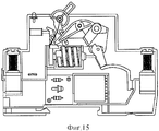
Фиг.15 - схематичный вид, иллюстрирующий вариант осуществления 6 по настоящему изобретению для замкнутого положения.15 is a schematic view illustrating an embodiment 6 of the present invention for a closed position.
Фиг.16 - схематичный вид, иллюстрирующий вариант осуществления 6 по настоящему изобретению для положения самоблокировки.16 is a schematic view illustrating an embodiment 6 of the present invention for a self-locking position.
Фиг.17 - схематичный вид, иллюстрирующий вариант осуществления 7 по настоящему изобретению для замкнутого положения.17 is a schematic view illustrating an embodiment 7 of the present invention for a closed position.
Фиг.18 - схематичный вид, иллюстрирующий вариант осуществления 7 по настоящему изобретению для положения самоблокировки.Fig. 18 is a schematic view illustrating an embodiment 7 of the present invention for a self-locking position.
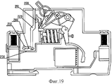
Фиг.19 - схематичный вид, иллюстрирующий вариант осуществления 8 по настоящему изобретению для разомкнутого положения.19 is a schematic view illustrating an embodiment 8 of the present invention for an open position.
Фиг.20 - схематичный вид, иллюстрирующий вариант осуществления 8 по настоящему изобретению для положения самоблокировки.20 is a schematic view illustrating an embodiment 8 of the present invention for a self-locking position.
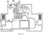
Фиг.21 - схематичный вид, иллюстрирующий вариант осуществления 9 по настоящему изобретению для разомкнутого положения.21 is a schematic view illustrating an embodiment 9 of the present invention for an open position.
Фиг.22 - схематичный вид, иллюстрирующий вариант осуществления 9 по настоящему изобретению для положения самоблокировки.22 is a schematic view illustrating an embodiment 9 of the present invention for a self-locking position.
Фиг.23 - схематичный вид, иллюстрирующий вариант осуществления 10 по настоящему изобретению для разомкнутого положения.23 is a schematic view illustrating an
Фиг.24 - схематичный вид, иллюстрирующий вариант осуществления 10 по настоящему изобретению для положения самоблокировки.24 is a schematic view illustrating an
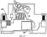
Фиг.25 - схематичный вид, иллюстрирующий вариант осуществления 11 по настоящему изобретению для разомкнутого положения.25 is a schematic view illustrating an embodiment 11 of the present invention for an open position.
Фиг.26 - схематичный вид, иллюстрирующий вариант осуществления 11 по настоящему изобретению для положения самоблокировки.26 is a schematic view illustrating an embodiment 11 of the present invention for a self-locking position.
Фиг.27 - схематичный вид, иллюстрирующий вариант осуществления 12 по настоящему изобретению для разомкнутого положения.27 is a schematic view illustrating an embodiment 12 of the present invention for an open position.
Фиг.28 - схематичный вид, иллюстрирующий вариант осуществления 12 по настоящему изобретению для положения самоблокировки.28 is a schematic view illustrating an embodiment 12 of the present invention for a self-locking position.
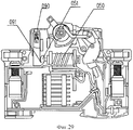
Фиг.29 - схематичный вид, иллюстрирующий вариант осуществления 13 по настоящему изобретению для разомкнутого положения.29 is a schematic view illustrating an embodiment 13 of the present invention for an open position.
Фиг.30 - схематичный вид, иллюстрирующий вариант осуществления 13 по настоящему изобретению для положения самоблокировки.30 is a schematic view illustrating an embodiment 13 of the present invention for a self-locking position.
Фиг.31 - схематичный вид, иллюстрирующий вариант осуществления 14 по настоящему изобретению для разомкнутого положения.Fig. 31 is a schematic view illustrating an embodiment 14 of the present invention for an open position.
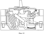
Фиг.32 - схематичный вид, иллюстрирующий вариант осуществления 14 по настоящему изобретению для положения самоблокировки.32 is a schematic view illustrating an embodiment 14 of the present invention for a self-locking position.
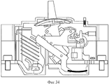
Фиг.33 - схематичный вид, иллюстрирующий вариант осуществления 15 по настоящему изобретению для разомкнутого положения.33 is a schematic view illustrating an embodiment 15 of the present invention for an open position.
Фиг.34 - схематичный вид, иллюстрирующий вариант осуществления 15 по настоящему изобретению для положения самоблокировки.Fig. 34 is a schematic view illustrating an embodiment 15 of the present invention for a self-locking position.
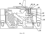
Фиг.35 - схематичный вид, иллюстрирующий вариант осуществления 16 по настоящему изобретению для разомкнутого положения.Fig. 35 is a schematic view illustrating an embodiment 16 of the present invention for an open position.
Фиг.36 - схематичный вид, иллюстрирующий вариант осуществления 16 по настоящему изобретению для положения самоблокировки.Fig. 36 is a schematic view illustrating an embodiment 16 of the present invention for a self-locking position.
Фиг.37 - схематичный вид, иллюстрирующий механизм самоблокировки при коротком замыкании по варианту осуществления 16 настоящего изобретения.37 is a schematic view illustrating a short-circuit self-locking mechanism of Embodiment 16 of the present invention.
Фиг.38 - чертеж в аксонометрии, иллюстрирующий механизм самоблокировки при коротком замыкании по варианту осуществления 16 настоящего изобретения.Fig. 38 is a perspective view illustrating a short-circuit self-locking mechanism of Embodiment 16 of the present invention.
Фиг.39 - принципиальная схема, иллюстрирующая цепь управления электромагнитом, управляемую реле максимального тока по настоящему изобретению.Fig. 39 is a circuit diagram illustrating an electromagnet control circuit controlled by an overcurrent relay of the present invention.
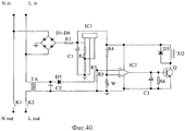
Фиг.40 - принципиальная схема, иллюстрирующая цепь управления электромагнитом, управляемую трансформатором по настоящему изобретению.40 is a circuit diagram illustrating an electromagnet control circuit controlled by a transformer of the present invention.
Фиг.41 - принципиальная схема, иллюстрирующая цепь управления самоблокировки, электрически управляемую реле максимального тока по настоящему изобретению.Fig. 41 is a circuit diagram illustrating a self-locking control circuit, an electrically controlled overcurrent relay of the present invention.
Фиг.42 - принципиальная схема, иллюстрирующая цепь управления самоблокировки, электрически управляемую трансформатором по настоящему изобретению.42 is a circuit diagram illustrating a self-locking control circuit electrically controlled by a transformer of the present invention.
Фиг.43 - принципиальная схема, иллюстрирующая цепь управления электромагнитом, напрямую управляемую трехфазным реле максимального тока по настоящему изобретению.43 is a circuit diagram illustrating an electromagnet control circuit directly controlled by the three-phase overcurrent relay of the present invention.
Фиг.44 - принципиальная схема, иллюстрирующая цепь управления электромагнитом, управляемую трехфазным реле максимального тока по настоящему изобретению.Fig. 44 is a circuit diagram illustrating an electromagnet control circuit controlled by the three-phase overcurrent relay of the present invention.
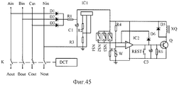
Фиг.45 - принципиальная схема, иллюстрирующая цепь управления самоблокировки, электрически управляемую трехфазным реле максимального тока по настоящему изобретению.Fig. 45 is a circuit diagram illustrating a self-locking control circuit electrically controlled by a three-phase overcurrent relay of the present invention.
Используемые обозначения: 010 - корпус; 020 - ручка; 030 - перемычка самоблокировки; 040 - рычажный механизм размыкания; 050 - механизм самоблокировки при коротком замыкании; 051 - сердечник; 060 - биметаллическая пластина; 070 - подвижный нож; 080 - подвижный контакт; 090 - кнопка; 091 - выступ кнопки; 092 - удлиненная пластина кнопки; 093 - штифт кнопки; 100 - поворотный стержень; 101 - паз поворотного стержня; 110 - рычаг; 120 - магнитный элемент; 130 - электромагнит; 131 - сердечник электромагнита; 140 - реле максимального тока; 150 - трансформатор; 160 - цепь управления; 170 - удлиненный стержень электромагнита; 180 - удлиненная пластина кнопки; 181 - выступ удлиненной пластины кнопки; 190 - удлиненный стержень рычажного механизма размыкания; 191 - паз удлиненного стержня; 200 - поворотный вал; 210 - поворотная пластина; 220 - пусковой ползун; 230 - внутренний проводник размыкателя цепи; 240 - магнитная полка; 250 - пружина; 260 - опорная рамка; 270 - поворотный рычаг; 271 - выступающий край поворотного рычага; 280 - пружина кручения; 290 - ограничитель; 300 - поворотная втулка; 301 - внутренняя спиральная канавка поворотной втулки; 302 - бобышка поворотной втулки; 310 - кожух; 311 - внутренний кольцевой выступ кожуха; 320 - подвижная вставка; 321 - паз подвижной вставки; 322 - внешняя выступающая кромка подвижной вставки; 330 - пружина растяжения; 340 - пружина сжатия.Used notations: 010 - case; 020 - pen; 030 - self-locking jumper; 040 - lever opening mechanism; 050 - self-locking mechanism during short circuit; 051 - core; 060 - bimetallic plate; 070 - movable knife; 080 - movable contact; 090 - button; 091 - button protrusion; 092 - an elongated button plate; 093 - button pin; 100 - rotary rod; 101 - groove of the rotary rod; 110 - lever; 120 - a magnetic element; 130 - electromagnet; 131 - core of the electromagnet; 140 - overcurrent relay; 150 - transformer; 160 - control circuit; 170 is an elongated rod of an electromagnet; 180 - elongated button plate; 181 - protrusion of the elongated button plate; 190 - an elongated rod of the lever opening mechanism; 191 - groove of the elongated shaft; 200 - rotary shaft; 210 - rotary plate; 220 - launch slider; 230 - internal circuit breaker conductor; 240 - magnetic shelf; 250 - spring; 260 - supporting frame; 270 - rotary lever; 271 - the protruding edge of the pivot arm; 280 - torsion spring; 290 - limiter; 300 - rotary sleeve; 301 - inner spiral groove of the rotary sleeve; 302 - boss of the rotary sleeve; 310 - casing; 311 - inner annular protrusion of the casing; 320 - movable insert; 321 — groove of the movable insert; 322 - the outer protruding edge of the movable insert; 330 - tension spring; 340 - compression spring.
Лучший вариант осуществления изобретенияThe best embodiment of the invention
Настоящее изобретение далее будет подробно проиллюстрировано с использованием чертежей и описания вариантов осуществления.The present invention will now be illustrated in detail using the drawings and description of embodiments.
Настоящее изобретение имеет конструкцию и поддерживает все функции предшествующего размыкателя цепи, но при этом имеет смонтированный в нем механизм самоблокировки при коротком замыкании, который включает узел самоблокировки, выполненный для удерживания рычажного механизма размыкания в положении защиты от короткого замыкания, и узел восстановления, выполненный для воздействия на рычажный механизм размыкания с целью его возврата в исходное положение.The present invention has a structure and supports all the functions of the preceding circuit breaker, but it has a short-circuit self-locking mechanism mounted therein, which includes a self-locking unit designed to hold the lever opening mechanism in the short-circuit protection position, and a recovery unit made to act on the lever opening mechanism in order to return it to its original position.
Вариант осуществления 1
Узел самоблокировки по настоящему изобретению включает рычаг с магнитным элементом, расположенным на его нижнем конце, и поворотный стержень, нижний конец которого шарнирно закреплен на корпусе размыкателя цепи. Узел восстановления включает кнопку с пружиной сжатия, расположенную в ней, которая соединена с поворотным стержнем. Рычаг расположен рядом с биметаллической пластиной размыкателя цепи. Средняя часть рычага шарнирно закреплена на корпусе размыкателя цепи, а верхняя часть рычага примыкает к одной стороне поворотного стержня выше шарнирно закрепленного конца поворотного стержня. Другая сторона поворотного стержня контактирует с верхней частью рычажного механизма размыкания. В верхней части поворотного стержня имеется паз. На нижней части кнопки выполнен выступ. Когда пружина сжатия в кнопке сжимается, выступ, расположенный на нижней части кнопки, помещается в паз, расположенный в верхней части поворотного стержня, как показано на фиг.5.The self-locking assembly of the present invention includes a lever with a magnetic element located at its lower end, and a pivoting rod, the lower end of which is pivotally mounted on the circuit breaker housing. The recovery unit includes a button with a compression spring located in it, which is connected to the pivot rod. The lever is located next to the bimetallic circuit breaker plate. The middle part of the lever is pivotally mounted on the circuit breaker housing, and the upper part of the lever is adjacent to one side of the pivot rod above the pivotally attached end of the pivot rod. The other side of the pivot rod contacts the upper part of the link opening mechanism. There is a groove in the upper part of the pivot rod. A protrusion is made on the bottom of the button. When the compression spring in the button is compressed, the protrusion located on the lower part of the button is placed in the groove located in the upper part of the pivot rod, as shown in FIG.
Принцип действия по этому варианту осуществления является следующим. Когда происходит короткое замыкание, величина тока, протекающего по биметаллической пластине, является намного большей, чем значение, заданное для размыкателя цепи. Вокруг биметаллической пластины образуется сильное магнитное поле, которое притягивает магнитный элемент, расположенный на нижнем конце рычага, таким образом заставляя рычаг поворачиваться. (Если происходит обычная перегрузка, то магнитное поле, образующееся вокруг биметаллической пластины, не является настолько сильным, чтобы притягивать магнитный элемент, расположенный в нижней части рычага.) Верхний конец рычага толкает и поворачивает поворотный стержень, и в свою очередь начинает поворачиваться рычажный механизм размыкания, который взаимодействует с механизмом самоблокировки при коротком замыкании, размыкая размыкатель цепи. В то же время, поворот поворотного стержня оказывает действие на выступ, расположенный в нижней части кнопки так, чтобы он вышел из паза, расположенного в верхней части поворотного стержня, что заставляет пружину сжатия вернуться в первоначальное положение. Выступ, расположенный в верхней части кнопки, смещается вверх вместе с кнопкой и затем упирается в одну сторону поворотного стержня, как показано на фиг.6. Таким образом, рычаг возвращается в исходное положение, но поворотный стержень не может вернуться в исходное положение после срабатывания размыкателя цепи. Другими словами, верхняя часть поворотного стержня будет удерживать рычажный механизм размыкания в разомкнутом положении так, что размыкатель цепи не может быть замкнут, даже если замкнута ручка, которая обеспечивает самоблокировку при коротком замыкании. Для возврата необходимо нажать кнопку, благодаря чему выступ, расположенный на нижнем конце кнопки, войдет в паз, расположенный в верхней части поворотного стержня, что приведет к возврату поворотного стержня в исходное положение и далее к возврату в исходное положение рычажного механизма размыкания так, что размыкатель цепи может быть замкнут за счет включения ручкой.The operating principle of this embodiment is as follows. When a short circuit occurs, the amount of current flowing through the bimetallic plate is much larger than the value set for the circuit breaker. A strong magnetic field is formed around the bimetallic plate, which attracts a magnetic element located at the lower end of the lever, thereby causing the lever to rotate. (If normal overload occurs, the magnetic field generated around the bimetallic plate is not so strong as to attract the magnetic element located at the bottom of the lever.) The upper end of the lever pushes and rotates the pivot rod, and in turn, the lever opening mechanism begins to turn which interacts with the self-locking mechanism during a short circuit, opening the circuit breaker. At the same time, the rotation of the pivot rod has an effect on the protrusion located in the lower part of the button so that it comes out of the groove located in the upper part of the pivot rod, which causes the compression spring to return to its original position. The protrusion located at the top of the button moves upward with the button and then abuts against one side of the pivot rod, as shown in FIG. 6. Thus, the lever returns to its original position, but the pivot rod cannot return to its original position after the circuit breaker is activated. In other words, the upper part of the pivoting rod will hold the lever opening mechanism in the open position so that the circuit breaker cannot be closed, even if the handle is closed, which provides self-locking during a short circuit. To return, you must press the button, so that the protrusion located on the lower end of the button will go into the groove located at the top of the pivot rod, which will return the pivot rod to its original position and then return to the initial position of the lever opening mechanism so that the switch The circuit can be closed by turning on the handle.
Вариант осуществления 2Embodiment 2
Узел самоблокировки по настоящему изобретению включает электромагнит, реле максимального тока и поворотный стержень, нижний конец которого шарнирно закреплен на корпусе размыкателя цепи, причем все эти элементы расположены в корпусе размыкателя цепи. Узел восстановления подобен узлу восстановления по варианту осуществления 1. Трубка реле максимального тока расположена вблизи внутреннего проводника размыкателя цепи. Электромагнит размещен с одной стороны поворотного стержня. Катушка электромагнита соединена с реле максимального тока последовательно и далее соединена с источником питания размыкателя цепи. Сердечник электромагнита контактирует с одной стороной поворотного стержня выше точки шарнирного закрепления поворотного стержня. В остальном конструкция подобна варианту осуществления 1, как показано на фиг.7.The self-locking assembly of the present invention includes an electromagnet, an overcurrent relay, and a pivot rod, the lower end of which is pivotally mounted to the circuit breaker housing, all of which are located in the circuit breaker housing. The recovery unit is similar to the recovery unit in
Принцип действия по этому варианту осуществления является следующим. Когда происходит короткое замыкание, величина тока, протекающего через внутренний проводник размыкателя цепи, становится намного выше значения, заданного для размыкателя цепи. Вокруг внутреннего проводника наводится сильное магнитное поле, притягивающее якорь реле максимального тока. Напряжение подается на катушку электромагнита, и сердечник электромагнита движется, толкая и поворачивая поворотный стержень, из-за чего происходит нажатие на рычажный механизм размыкания и его поворот, как показано на фиг.8. В остальном принцип действия схож с вариантом осуществления 1.The operating principle of this embodiment is as follows. When a short circuit occurs, the amount of current flowing through the inner conductor of the circuit breaker becomes much higher than the value set for the circuit breaker. A strong magnetic field is induced around the inner conductor, attracting the armature of the overcurrent relay. The voltage is supplied to the coil of the electromagnet, and the core of the electromagnet moves, pushing and turning the pivot rod, due to which the lever is opened and rotated, as shown in Fig. 8. Otherwise, the principle of operation is similar to
Вариант осуществления 3Embodiment 3
Узел самоблокировки по настоящему изобретению включает электромагнит, трансформатор и поворотный стержень, нижний конец которого шарнирно закреплен на корпусе размыкателя цепи, все эти элементы расположены в корпусе размыкателя цепи. Конструкция узла восстановления сходна с конструкцией по варианту осуществления 1. Внутренние проводники размыкателя цепи проходят через трансформатор, выход которого соединен с цепью управления для управления движением электромагнита. Электромагнит выполнен прилегающим к поворотному стержню, а в остальном конструкция сходна с вариантом осуществления 2, как показано на фиг.9.The self-locking assembly of the present invention includes an electromagnet, a transformer and a pivot rod, the lower end of which is pivotally mounted to the circuit breaker housing, all of these elements are located in the circuit breaker housing. The design of the recovery unit is similar to the design of
Принцип действия по данному варианту осуществления является следующим. Когда происходит короткое замыкание, величина тока, протекающего через внутренние проводники размыкателя цепи, становится намного выше значения, заданного для размыкателя цепи. Трансформатор подает сигнал тока в цепь управления, которая приводит в действие катушку электромагнита так, что сердечник электромагнита движется, толкая и поворачивая поворотный стержень, вследствие чего происходит нажатие на рычажный механизм размыкания и его поворот, как показано на фиг.10. В остальном принцип действия схож с вариантом осуществления 1.The operating principle of this embodiment is as follows. When a short circuit occurs, the amount of current flowing through the internal conductors of the circuit breaker becomes much higher than the value set for the circuit breaker. The transformer supplies a current signal to the control circuit, which drives the electromagnet coil so that the core of the electromagnet moves, pushing and turning the pivot rod, as a result of which the lever opening mechanism is pressed and rotated, as shown in FIG. Otherwise, the principle of operation is similar to
Вариант осуществления 4Embodiment 4
Узел самоблокировки по настоящему изобретению включает электромагнит и реле максимального тока, которые расположены в корпусе размыкателя цепи. Удлиненный стержень с выступом на крайней части закреплен на сердечнике электромагнита. Конец удлиненного стержня примыкает к верхней части рычажного механизма размыкания размыкателя цепи. Узел восстановления образован кнопкой с расположенной в ней пружиной сжатия, входящей в зацепление с удлиненным стержнем. Внутренний торец кнопки соединен с удлиненной пластиной, имеющей ступенчатые канавки. Удлиненная пластина расположена между электромагнитом и рычажным механизмом размыкания. Участок ступенчатой канавки в удлиненной пластине, расположенный рядом с электромагнитом, выполнен в виде неглубокой канавки, а участок ступенчатой канавки, расположенный рядом с рычажным механизмом размыкания, выполнен в виде глубокой канавки. Когда пружина сжатия в кнопке сжимается, выступ крайней части удлиненного стержня входит в менее глубокую канавку. Трубка реле максимального тока расположена вблизи внутренних проводников размыкателя цепи, как показано на фиг.11. Катушка электромагнита соединена с реле максимального тока последовательно и далее соединена с источником питания размыкателя цепи.The self-locking assembly of the present invention includes an electromagnet and an overcurrent relay, which are located in a circuit breaker housing. An elongated rod with a protrusion on the extreme part is fixed to the core of the electromagnet. The end of the elongated rod is adjacent to the upper part of the lever mechanism for opening the circuit breaker. The recovery unit is formed by a button with a compression spring located in it, which engages with an elongated shaft. The inner end of the button is connected to an elongated plate having stepped grooves. An elongated plate is located between the electromagnet and the lever opening mechanism. The section of the stepped groove in the elongated plate located next to the electromagnet is made in the form of a shallow groove, and the section of the stepped groove located next to the lever opening mechanism is made in the form of a deep groove. When the compression spring in the button is compressed, the protrusion of the extreme part of the elongated shaft enters the less deep groove. The overcurrent relay tube is located near the inner conductors of the circuit breaker, as shown in FIG. 11. The electromagnet coil is connected to the overcurrent relay in series and then connected to a circuit breaker power source.
Принцип действия данного варианта осуществления является следующим. Когда происходит короткое замыкание, величина тока, протекающего во внутренних проводниках размыкателя цепи, становится намного выше значения, заданного для размыкателя цепи. Вокруг внутренних проводников наводится сильное магнитное поле, которое притягивает якорь реле максимального тока. Напряжение подается на катушку электромагнита, и сердечник электромагнита движется, нажимая и поворачивая поворотный стержень, вследствие чего происходит нажатие и поворот рычажного механизма размыкания, который взаимодействует с механизмом самоблокировки при коротком замыкании для размыкания размыкателя цепи. В то же время, перемещение удлиненного стержня и возвращение пружины сжатия, расположенной в кнопке, вызывает перемещение выступа крайней части удлиненного стержня из неглубокой канавки в глубокую канавку ступенчатой канавки удлиненной пластины. Выступ крайней части удлиненного стержня входит в глубокую канавку ступенчатой канавки и не может вернуться в первоначальное положение. Рычажный механизм размыкания удерживается в разомкнутом положении так, что размыкатель цепи не может быть замкнут, даже если замыкается ручка, за счет чего достигается самоблокировка при коротком замыкании, как показано на фиг.12. Для возврата необходимо нажать кнопку, которая возвращает в исходное положение сердечник электромагнита и позволяет выступу крайней части удлиненного стержня выйти из глубокой канавки ступенчатой канавки удлиненной пластины и переместиться в неглубокую канавку. После того как рычажный механизм размыкания возвращается в исходное положение, размыкатель цепи может быть опять замкнут за счет замыкания ручкой.The principle of operation of this embodiment is as follows. When a short circuit occurs, the amount of current flowing in the internal conductors of the circuit breaker becomes much higher than the value set for the circuit breaker. A strong magnetic field is induced around the inner conductors, which attracts the armature of the overcurrent relay. The voltage is supplied to the coil of the electromagnet, and the core of the electromagnet moves by pressing and turning the pivot rod, as a result of which the lever mechanism of opening is pressed and rotated, which interacts with the self-locking mechanism during short circuit to open the circuit breaker. At the same time, moving the elongated shaft and returning the compression spring located in the button causes the protrusion of the extreme part of the elongated rod from the shallow groove to the deep groove of the stepped groove of the elongated plate. The protrusion of the extreme part of the elongated shaft enters the deep groove of the stepped groove and cannot return to its original position. The lever opening mechanism is held in the open position so that the circuit breaker cannot be closed even if the handle closes, thereby achieving self-locking during short circuit, as shown in Fig. 12. To return, you must press the button, which returns the core of the electromagnet to its original position and allows the protrusion of the extreme part of the elongated rod to exit the deep groove of the stepped groove of the elongated plate and move to a shallow groove. After the lever opening mechanism returns to its original position, the circuit breaker can be closed again by closing with a handle.
Вариант осуществления 5Embodiment 5
Узел самоблокировки по настоящему изобретению включает электромагнит, трансформатор и цепь управления, которые расположены в корпусе размыкателя цепи. Внутренние проводники размыкателя цепи проходят через трансформатор, выход которого соединен с цепью управления для управления перемещением электромагнита, как показано на фиг.40. В остальном конструкция сходна с вариантом осуществления 4, как показано на фиг.13.The self-locking assembly of the present invention includes an electromagnet, a transformer and a control circuit, which are located in the circuit breaker housing. The internal conductors of the circuit breaker pass through a transformer, the output of which is connected to a control circuit for controlling the movement of the electromagnet, as shown in Fig. 40. The rest of the design is similar to embodiment 4, as shown in FIG.
Принцип действия данного варианта осуществления сходен с вариантом осуществления 4, за исключением того, что электромагнит управляется цепью управления, как показано на фиг.14.The principle of operation of this embodiment is similar to embodiment 4, except that the electromagnet is controlled by a control circuit, as shown in FIG.
Вариант осуществления 6Option exercise 6
Узел самоблокировки по настоящему изобретению включает электромагнит, реле максимального тока и цепь управления самоблокировки, электрически управляемую реле максимального тока, как показано на фиг.41, при этом все элементы расположены в корпусе размыкателя цепи. Электромагнит и реле максимального тока соединены с цепью управления самоблокировки, электрически управляемой реле максимального тока. Узел восстановления сформирован кнопкой. Трубка реле максимального тока расположена вблизи внутренних проводников размыкателя цепи. Сердечник электромагнита контактирует с верхним концом рычажного механизма размыкания, как показано на фиг.15.The self-locking assembly of the present invention includes an electromagnet, an overcurrent relay and a self-locking control circuit, an electrically controlled overcurrent relay, as shown in FIG. 41, with all the elements located in the circuit breaker housing. The electromagnet and overcurrent relay are connected to a self-locking control circuit, an electrically controlled overcurrent relay. The recovery node is formed by a button. The overcurrent relay tube is located near the internal conductors of the circuit breaker. The core of the electromagnet is in contact with the upper end of the link opening mechanism, as shown in FIG.
Принцип действия по данному варианту осуществления является следующим. Когда происходит короткое замыкание, величина тока, протекающего через внутренние проводники, становится намного выше значения, заданного для размыкателя цепи. Вокруг внутренних проводников наводится сильное магнитное поле, которое притягивает якорь реле максимального тока. Цепь управления самоблокировки, электрически управляемая реле максимального тока, подает напряжение на катушку электромагнита. Сердечник электромагнита движется, нажимая и поворачивая рычажный механизм размыкания, который взаимодействует с механизмом самоблокировки при коротком замыкании для размыкания размыкателя цепи. Рычажный механизм размыкания удерживается в разомкнутом положении и не может быть возвращен, при этом размыкатель цепи не может быть замкнут, даже если замкнута ручка, за счет чего достигается самоблокировка при коротком замыкании, как показано на фиг.16. Для возврата необходимо нажать на кнопку для остановки цепи управления самоблокировки, электрически управляемой реле максимального тока. Напряжение не подается на катушку электромагнита, и сердечник электромагнита возвращается в исходное положение. После того как рычажный механизм размыкания возвратится в исходное положение, размыкатель цепи может быть опять замкнут за счет замыкания ручкой.The operating principle of this embodiment is as follows. When a short circuit occurs, the amount of current flowing through the internal conductors becomes much higher than the value set for the circuit breaker. A strong magnetic field is induced around the inner conductors, which attracts the armature of the overcurrent relay. The self-locking control circuit, electrically controlled by the overcurrent relay, supplies voltage to the electromagnet coil. The core of the electromagnet moves by pressing and turning the lever opening mechanism, which interacts with the self-locking mechanism during a short circuit to open the circuit breaker. The lever opening mechanism is held in the open position and cannot be returned, while the circuit breaker cannot be closed, even if the handle is closed, thereby achieving self-locking during short circuit, as shown in Fig. 16. To return, you must press the button to stop the self-locking control circuit, an electrically controlled overcurrent relay. No voltage is supplied to the coil of the electromagnet, and the core of the electromagnet returns to its original position. After the lever opening mechanism returns to its original position, the circuit breaker can be closed again by closing with a handle.
Вариант осуществления 7Embodiment 7
Узел самоблокировки по настоящему изобретению включает электромагнит, трансформатор и цепь управления самоблокировки, электрически управляемую трансформатором, как показано на фиг.42, где все эти элементы расположены в корпусе размыкателя цепи. Узел восстановления сформирован кнопкой переключения. Внутренние проводники размыкателя цепи проходят через трансформатор, выход которого соединен с цепью управления самоблокировки, электрически управляемой трансформатором. Сердечник электромагнита контактирует с верхней частью рычажного механизма размыкания размыкателя цепи, как показано на фиг.17.The self-locking assembly of the present invention includes an electromagnet, a transformer, and a self-locking control circuit electrically controlled by a transformer, as shown in FIG. 42, where all these elements are located in the circuit breaker housing. The recovery node is formed by a switch button. The internal conductors of the circuit breaker pass through a transformer whose output is connected to a self-locking control circuit electrically controlled by the transformer. The core of the electromagnet is in contact with the upper part of the lever mechanism for opening the circuit breaker, as shown in Fig.17.
Принцип действия по настоящему варианту осуществления сходен с вариантом осуществления 6 за исключением использования другой принципиальной схемы электрической цепи для цепи управления самоблокировки с электрическим управлением, как показано на фиг.14.The principle of operation of the present embodiment is similar to that of embodiment 6 except for using another circuit diagram for the electric self-locking control circuit, as shown in FIG.
Вариант осуществления 8Option exercise 8
Узел самоблокировки по настоящему изобретению включает магнитный элемент, который выполнен на поворотной пластине, средняя часть которой установлена на поворотном валу, установленном на внутренней стенке корпуса. Поворотная пластина может свободно поворачиваться на поворотном валу. Магнитный элемент расположена на первом конце поворотной пластины, которая может быть выполнена в виде намагниченной или стальной пластины, или содержать в себе магнитный носитель, который может притягиваться магнитным полем. Узел восстановления включает пусковой ползун, выполненный в форме стержня, первый конец которого является отпирающим и соединен со вторым концом поворотной пластины. Второй конец пускового ползуна является кнопкой возврата, выступающей из корпуса так, что пусковой ползун может перемещаться в определенном направлении. Пусковой ползун также имеет выступ, который примыкает к рычажному механизму размыкания, как показано на фиг.19.The self-locking assembly of the present invention includes a magnetic element, which is made on a rotary plate, the middle part of which is mounted on a rotary shaft mounted on the inner wall of the housing. The pivot plate can rotate freely on the pivot shaft. The magnetic element is located at the first end of the rotary plate, which can be made in the form of a magnetized or steel plate, or contain a magnetic carrier that can be attracted by a magnetic field. The recovery unit includes a launch slider made in the form of a rod, the first end of which is unlocked and connected to the second end of the rotary plate. The second end of the trigger slide is a reset button protruding from the housing so that the trigger slide can move in a certain direction. The trigger slider also has a protrusion that is adjacent to the lever opening mechanism, as shown in Fig.19.
На фиг.20 показана внутренняя конструкция по данному варианту осуществления, при возникновении короткого замыкания. В конструкции по настоящему изобретению, при возникновении короткого замыкания, концевые выходы цепи наводят сильное магнитное поле, и поворотная пластина свободно поворачивается на поворотном валу до тех пор, пока ее первый конец с расположенным на нем магнитным элементом не примкнет к концевым выходам цепи, за счет чего приводится в действие пусковой ползун, который перемещается вверх. Кнопка возврата выступает из корпуса для определения размыкания сети при коротком замыкании. Выступ на кнопке возврата толкает примыкающую к нему часть рычажного механизма размыкания. Даже если сильное магнитное поле исчезнет после размыкания цепи, то пусковой ползун не может вернуться в исходное положение из-за усилия, создаваемого пружиной, размещенной в кнопке возврата, и выступом кнопки. Таким образом, настоящее изобретение не только обеспечивает защиту от короткого замыкания, но и самоблокировку при коротком замыкании за счет применения оригинальной конструкции. Ручка не может быть перемещена для замыкания размыкателя цепи до тех пор, пока пользователь не нажмет на кнопку возврата, что повышает уровень безопасности.On Fig shows the internal structure according to this variant implementation, when a short circuit occurs. In the structure of the present invention, when a short circuit occurs, the end outputs of the circuit induce a strong magnetic field, and the rotary plate rotates freely on the rotary shaft until its first end with the magnetic element located on it adjoins the end outputs of the circuit, due to which triggers the launch slider, which moves up. A return button protrudes from the housing to detect an open circuit during a short circuit. The protrusion on the return button pushes the adjacent part of the lever opening mechanism. Even if the strong magnetic field disappears after the circuit is opened, the launch slider cannot return to its original position due to the force created by the spring located in the return button and the protrusion of the button. Thus, the present invention not only provides protection against short circuit, but also self-locking during short circuit due to the use of the original design. The handle cannot be moved to close the circuit breaker until the user presses the return button, which increases security.
Вариант осуществления 9Embodiment 9
По сравнению с вариантом осуществления 8, особенностью данного варианта осуществления является то, что магнитный элемент представляет собой магнитную полку с двумя магнитными элементами, расположенными соответственно на ее двух концах. Магнитный элемент может быть выполнен в виде намагниченной или стальной пластины или содержать в себе магнитный носитель, который может притягиваться магнитным полем. Узел восстановления включает пусковой ползун, выполненный в форме стержня, первый конец которого является отпирающим и соединен со средней частью магнитной полки. Второй конец пускового ползуна является кнопкой возврата, выступающей из корпуса так, что пусковой ползун может перемещаться в определенном направлении. Пусковой ползун также имеет выступ, который примыкает к рычажному механизму размыкания, как показано на фиг.21.Compared with embodiment 8, a feature of this embodiment is that the magnetic element is a magnetic shelf with two magnetic elements located respectively at its two ends. The magnetic element can be made in the form of a magnetized or steel plate or contain a magnetic carrier that can be attracted by a magnetic field. The recovery unit includes a launch slider made in the form of a rod, the first end of which is unlocked and connected to the middle part of the magnetic shelf. The second end of the trigger slide is a reset button protruding from the housing so that the trigger slide can move in a certain direction. The trigger slider also has a protrusion that is adjacent to the lever opening mechanism, as shown in Fig.21.
На фиг.20 показана внутренняя конструкция по данному варианту осуществления при возникновении короткого замыкания. В конструкции по настоящему изобретению, при возникновении короткого замыкания, концевые выходы цепи наводят сильное магнитное поле, и магнитная полка сразу перемещается вверх до тех пор, пока магнитные элементы не примкнут к выходным концам цепи, которая приводит в действие пусковой ползун, и заставляет его двигаться вверх. Кнопка возврата выступает из корпуса для определения размыкания сети при коротком замыкании. Выступ кнопки толкает примыкающую к ней часть рычажного механизма размыкания. Даже если сильное магнитное поле исчезнет после размыкания цепи, то пусковой ползун не может вернуться в исходное положение из-за усилия, созданного пружиной, размещенной в кнопке возврата, и из-за выступа кнопки. Таким образом, настоящее изобретение не только обеспечивает защиту от короткого замыкания, но и самоблокировку при коротком замыкании за счет применения оригинальной конструкции. Ручка не может быть перемещена для замыкания размыкателя цепи до тех пор, пока пользователь не нажмет на кнопку возврата, что повышает уровень безопасности.FIG. 20 shows the internal structure of this embodiment when a short circuit occurs. In the structure of the present invention, when a short circuit occurs, the end outputs of the circuit induce a strong magnetic field, and the magnetic shelf immediately moves up until the magnetic elements are attached to the output ends of the circuit, which actuates the trigger, and makes it move up. A return button protrudes from the housing to detect an open circuit during a short circuit. The protrusion of the button pushes the adjacent part of the lever opening mechanism. Even if the strong magnetic field disappears after the circuit is opened, the launch slider cannot return to its original position due to the force created by the spring placed in the return button and because of the protrusion of the button. Thus, the present invention not only provides protection against short circuit, but also self-locking during short circuit due to the use of the original design. The handle cannot be moved to close the circuit breaker until the user presses the return button, which increases security.
Для избежания одновременного срабатывания магнитной полки и механизма активации при коротком замыкании при перегрузке под магнитной полкой предусмотрена опорная рамка. Опорная рамка расположена в корпусе и соединена с нижней частью магнитной полки с помощью пружины. Цепь генерирует силу притяжения в направлении магнитной полки, благодаря магнитному полю, наведенному при перегрузке. За счет силы пружины магнитная полка не будет при этом примыкать к выходным концам цепи.To avoid the simultaneous operation of the magnetic shelf and the activation mechanism during a short circuit during overload, a support frame is provided under the magnetic shelf. The support frame is located in the housing and is connected to the bottom of the magnetic shelf using a spring. The chain generates an attractive force in the direction of the magnetic shelf due to the magnetic field induced during overload. Due to the force of the spring, the magnetic shelf will not be adjacent to the output ends of the circuit.
Вариант осуществления 10
Узел самоблокировки по настоящему изобретению включает детекторную цепь короткого замыкания для определения наличия короткого замыкания и электромагнитный механизм активации. Детекторная цепь короткого замыкания включает в себя реле максимального тока, трубка которого установлена вблизи внутренних проводников размыкателя цепи. Когда происходит короткое замыкание, наводится сильное магнитное поле, действующее на две раздельные контактные пластинки в реле максимального тока так, что они притягиваются друг к другу. Узел восстановления содержит электромагнит с пусковым ползуном, находящимся на конце магнита электромагнита. Нижний конец пускового ползуна соединен с магнитом электромагнита, а верхний конец пускового ползуна является кнопкой возврата. После того как электромагнит запитан, магнит движется вверх, перемещая пусковой ползун. Пусковой ползун имеет выступ, который примыкает к рычажному механизму размыкания, как показано на фиг.23.The self-locking assembly of the present invention includes a short circuit detector circuit for detecting a short circuit and an electromagnetic activation mechanism. The short circuit detector circuit includes a maximum current relay, the tube of which is installed near the internal conductors of the circuit breaker. When a short circuit occurs, a strong magnetic field is induced, acting on two separate contact plates in the overcurrent relay so that they are attracted to each other. The recovery unit contains an electromagnet with a trigger slider located at the end of an electromagnet magnet. The lower end of the trigger slide is connected to the magnet of the electromagnet, and the upper end of the trigger slide is the return button. After the electromagnet is energized, the magnet moves upward, moving the trigger slider. The trigger slider has a protrusion that is adjacent to the lever opening mechanism, as shown in Fig.23.
На фиг.24 показана внутренняя конструкция по настоящему варианту осуществления при возникновении короткого замыкания. При возникновении короткого замыкания, выходные концы цепи вырабатывают сильное магнитное поле, и контактные пластинки в реле максимального тока притягиваются друг к другу, генерируя пусковой сигнал (принцип генерации этого сигнала будет раскрыт далее). Электромагнит механизма активации электромагнита срабатывает после получения пускового сигнала. Магнит движется вверх и заставляет пусковой ползун перемещаться вверх. Кнопка возврата выступает из корпуса для определения размыкания цепи при коротком замыкании. Выступ кнопки толкает примыкающую к нему часть рычажного механизма размыкания, заставляя его перемещаться. Даже если сильное магнитное поле пропадет после размыкания цепи, пусковой ползун не может вернуться в исходное положение из-за усилия, созданного пружиной в кнопке возврата, и из-за выступа кнопки. Таким образом, настоящее изобретение обеспечивает не только защиту от короткого замыкания, но и также обеспечивает самоблокировку при коротком замыкании благодаря оригинальной конструкции. Ручка не может быть передвинута для замыкания размыкателя цепи до тех пор, пока пользователь не нажмет на кнопку возврата, что повышает безопасность использования.24 shows the internal structure of the present embodiment when a short circuit occurs. When a short circuit occurs, the output ends of the circuit generate a strong magnetic field, and the contact plates in the overcurrent relay are attracted to each other, generating a trigger signal (the principle of generating this signal will be described later). The electromagnet activation mechanism electromagnet is triggered after receiving a start signal. The magnet moves up and causes the trigger to move up. A return button protrudes from the housing to detect an open circuit during a short circuit. The protrusion of the button pushes the adjacent part of the lever opening mechanism, forcing it to move. Even if a strong magnetic field disappears after the circuit is opened, the launch slider cannot return to its original position due to the force created by the spring in the return button and because of the protrusion of the button. Thus, the present invention provides not only protection against short circuit, but also provides self-locking during short circuit due to the original design. The handle cannot be moved to close the circuit breaker until the user presses the return button, which increases the safety of use.
Вариант осуществления 11Embodiment 11
Узел самоблокировки по настоящему изобретению включает детекторную цепь короткого замыкания для определения наличия короткого замыкания, которая включает в себя трансформатор, вставленный на внутренние проводники размыкателя цепи, и механизм активации электромагнита. Когда происходит короткое замыкание, сила тока возрастает и трансформатор генерирует сигнал напряжения. Узел восстановления содержит электромагнит с пусковым ползуном, установленным на конце магнита электромагнита. Нижний конец пускового ползуна соединен с магнитом электромагнита, а верхний конец пускового ползуна является кнопкой возврата. После срабатывания электромагнита магнит движется вверх, перемещая пусковой ползун. Пусковой ползун также имеет выступ, который примыкает к рычажному механизму размыкания, как показано на фиг.25.The self-locking assembly of the present invention includes a short circuit detection circuit for detecting a short circuit, which includes a transformer inserted on the internal conductors of the circuit breaker and an electromagnet activation mechanism. When a short circuit occurs, the current increases and the transformer generates a voltage signal. The recovery unit contains an electromagnet with a trigger slider mounted on the end of an electromagnet magnet. The lower end of the trigger slide is connected to the magnet of the electromagnet, and the upper end of the trigger slide is the return button. After the operation of the electromagnet, the magnet moves up, moving the launch slider. The trigger slider also has a protrusion that is adjacent to the lever opening mechanism, as shown in Fig.25.
На фиг.26 показана внутренняя конструкция по настоящему варианту осуществления при возникновении короткого замыкания. При возникновении короткого замыкания в обмотке трансформатора генерируется индуцированное напряжение, что вызывает пусковой сигнал. Электромагнит электромагнитного механизма активации срабатывает после получения пускового сигнала. Магнит движется вверх и заставляет двигаться вверх пусковой ползун. Кнопка возврата выступает из корпуса, указывая на то, что цепь разомкнута из-за короткого замыкания. Выступ кнопки толкает примыкающую к нему часть рычажного механизма размыкания. Даже если сильное магнитное поле пропадет после размыкания цепи, пусковой ползун не может вернуться в исходное положение из-за усилия, созданного пружиной в кнопке возврата, и из-за выступа кнопки. Таким образом, настоящее изобретение не только обеспечивает защиту от короткого замыкания, но и также обеспечивает самоблокировку при коротком замыкании благодаря оригинальной конструкции. Ручка не может быть передвинута для замыкания размыкателя цепи до тех пор, пока пользователь не нажмет на кнопку возврата, что повышает безопасность использования.FIG. 26 shows the internal structure of the present embodiment when a short circuit occurs. When a short circuit occurs in the transformer winding, an induced voltage is generated, which causes a start signal. The electromagnet of the electromagnetic activation mechanism is triggered after receiving a start signal. The magnet moves up and makes the launch slider move up. The reset button protrudes from the housing, indicating that the circuit is open due to a short circuit. The protrusion of the button pushes the adjacent part of the lever opening mechanism. Even if a strong magnetic field disappears after the circuit is opened, the launch slider cannot return to its original position due to the force created by the spring in the return button and because of the protrusion of the button. Thus, the present invention not only provides protection against short circuit, but also provides self-locking during short circuit due to the original design. The handle cannot be moved to close the circuit breaker until the user presses the return button, which increases the safety of use.
Вариант осуществления 12Embodiment 12
Узел самоблокировки по настоящему варианту осуществления включает поворотный рычаг, средняя часть которого шарнирно закреплена на корпусе размыкателя цепи. На поворотном рычаге установлена пружина кручения. Нижний конец поворотного рычага контактирует сердечником механизма активации при коротком замыкании, а верхний конец имеет выступающий край. Узел восстановления образован кнопкой с расположенной в ней пружиной сжатия, которая зацеплена с поворотным рычагом. На нижней части кнопки имеется выступ. Когда пружина сжатия в кнопке сжимается, выступ на нижней части кнопки располагается под выступающим краем верхнего конца поворотного рычага, как показано на фиг.27.The self-locking assembly of the present embodiment includes a pivot arm, the middle part of which is pivotally mounted to the circuit breaker housing. A torsion spring is mounted on the pivot arm. The lower end of the pivot arm contacts the core of the activation mechanism during a short circuit, and the upper end has a protruding edge. The recovery unit is formed by a button with a compression spring located in it, which is engaged with a rotary lever. There is a protrusion on the bottom of the button. When the compression spring in the button is compressed, the protrusion on the bottom of the button is located under the protruding edge of the upper end of the pivot arm, as shown in FIG.
Принцип действия по настоящему варианту осуществления является следующим. Когда происходит короткое замыкание, величина тока, протекающего в механизме активации при коротком замыкании, становится намного выше значения, установленного для размыкателя цепи, вследствие чего сердечник механизма активации при коротком замыкании толкает нижний конец рычажного механизма размыкания таким образом, чтобы повернуть рычажный механизм размыкания за счет усилия пружины кручения. Нижний конец поворотного рычага продолжает контактировать с сердечником механизма активации при коротком замыкании, а выступающий край верхнего конца поворотного рычага разъединяется с выступом, расположенным на нижнем конце кнопки, из-за поворота поворотного рычага таким образом, что пружина сжатия, расположенная в кнопке, возвращается в исходное положение, а выступ, расположенный на нижнем конце кнопки, двигается вверх, толкая кнопку до тех пор, пока она не упрется в поверхность выступающего края верхнего конца поворотного рычага, как показано на фиг.28. Сердечник механизма активации при коротком замыкании удерживается с помощью нижнего конца поворотного рычага и не может вернуться в исходное положение. Другими словами, сердечник механизма активации при коротком замыкании удерживает рычажный механизм размыкания в блокированном положении так, что размыкатель цепи не может быть замкнут, даже если замкнута ручка, что обеспечивает самоблокировку при коротком замыкании. Для сброса необходимо нажать на кнопку для перемещения выступа на нижнем конец кнопки под выступающий край верхнего конца поворотного рычага, таким образом возвращая сердечник механизма активации при коротком замыкании в исходное положение. После того как рычажный механизм размыкания вернулся в исходное положение, размыкатель цепи может быть вновь замкнут за счет замыкания ручкой.The principle of operation of the present embodiment is as follows. When a short circuit occurs, the current flowing in the activation mechanism during a short circuit becomes much higher than the value set for the circuit breaker, as a result of which the core of the activation mechanism during a short circuit pushes the lower end of the lever opening mechanism so as to rotate the lever opening mechanism due to torsion spring forces. The lower end of the pivot arm continues to contact the core of the activation mechanism during a short circuit, and the protruding edge of the upper end of the pivot arm is disconnected from the protrusion located on the lower end of the button due to the rotation of the pivot arm so that the compression spring located in the button returns to the initial position, and the protrusion located at the lower end of the button moves up, pushing the button until it abuts against the surface of the protruding edge of the upper end of the pivot arm, It is shown in Figure 28. The core of the activation mechanism during a short circuit is held by the lower end of the pivot arm and cannot return to its original position. In other words, the core of the activation mechanism during a short circuit keeps the lever opening mechanism in the locked position so that the circuit breaker cannot be closed even if the handle is closed, which ensures self-locking during a short circuit. To reset, you must press the button to move the protrusion on the lower end of the button under the protruding edge of the upper end of the pivot arm, thus returning the core of the activation mechanism during a short circuit to its original position. After the lever opening mechanism has returned to its original position, the circuit breaker can be closed again by closing the handle.
Вариант осуществления 13Embodiment 13
Узел самоблокировки и узел восстановления включают в себя кнопку с расположенной в ней пружиной сжатия, которая имеет выступ, сформированный на нижнем конце кнопки. Когда пружина сжатия сжата, выступ на нижнем конце кнопки располагается под сердечником механизма активации при коротком замыкании, как показано на фиг.29.The self-locking unit and the recovery unit include a button with a compression spring located therein, which has a protrusion formed at the lower end of the button. When the compression spring is compressed, a protrusion at the lower end of the button is located under the core of the short-circuit activation mechanism, as shown in FIG.
Принцип действия по настоящему варианту осуществления является следующим. Когда происходит короткое замыкание, величина тока, протекающего в механизме активации при коротком замыкании, становится намного больше значения, установленного для размыкателя цепи, из-за чего сердечник механизма активации при коротком замыкании толкает нижний конец рычажного механизма размыкания, заставляя механизм активации при коротком замыкании повернуться, тем самым размыкая размыкатель цепи. В то же время, движение сердечника механизма активации при коротком замыкании заставляет выступ, расположенный на нижнем конце кнопки, разъединиться с сердечником, после чего выступ движется вверх под действием возвращающей силы пружины сжатия в кнопке так, что выступ, расположенный на нижнем конце кнопки, соединяется одним концом с сердечником механизма активации при коротком замыкании, как показано на фиг.30. Сердечник механизма активации при коротком замыкании удерживается выступом, расположенным на нижнем конце кнопки и не может быть возвращен в исходное положение. Другими словами, сердечник механизма активации при коротком замыкании удерживает рычажный механизм размыкания в заблокированном положении так, что размыкатель цепи не может быть замкнут, даже если замкнута ручка, что обеспечивает самоблокировку при коротком замыкании. Для сброса необходимо нажать на кнопку для перемещения выступа на нижнем конце кнопки под выступающий край верхнего конца поворотного рычага, таким образом возвращая сердечник механизма активации при коротком замыкании в исходное положение. После того, как рычажный механизм размыкания вернулся в исходное положение, размыкатель цепи может быть замкнут за счет повторного замыкания ручки.The principle of operation of the present embodiment is as follows. When a short circuit occurs, the amount of current flowing in the activation mechanism during a short circuit becomes much larger than the value set for the circuit breaker, because of which the core of the activation mechanism during a short circuit pushes the lower end of the lever opening mechanism, causing the activation mechanism to rotate during a short circuit thereby breaking the circuit breaker. At the same time, the movement of the core of the activation mechanism during a short circuit causes the protrusion located on the lower end of the button to disconnect from the core, after which the protrusion moves upward under the action of the return force of the compression spring in the button so that the protrusion located on the lower end of the button is connected one end with the core of the short-circuit activation mechanism, as shown in FIG. The core of the activation mechanism during a short circuit is held by a protrusion located on the lower end of the button and cannot be returned to its original position. In other words, the core of the activation mechanism in the event of a short circuit keeps the lever opening mechanism in the locked position so that the circuit breaker cannot be closed even if the handle is closed, which ensures self-locking in the event of a short circuit. To reset, you must press the button to move the protrusion on the lower end of the button under the protruding edge of the upper end of the pivot arm, thus returning the core of the activation mechanism during a short circuit to its original position. After the lever opening mechanism has returned to its original position, the circuit breaker can be closed by re-closing the handle.
Эти узлы самоблокировки и восстановления имеют ограничители, смонтированные в корпусе размыкателя цепи для более устойчивой фиксации узла самоблокировки и узла восстановления в корпусе размыкателя цепи.These self-locking and recovery units have limiters mounted in the circuit breaker housing for more stable fixation of the self-locking unit and recovery unit in the circuit breaker housing.
Настоящее изобретение также может применяться в трехфазном автоматическом выключателе с литым корпусом (воздушный выключатель).The present invention can also be applied in a three-phase molded case circuit breaker (air circuit breaker).
Вариант осуществления 14Embodiment 14
Узел самоблокировки по настоящему изобретению включает электромагнит, реле максимального тока и поворотный стержень, нижний конец которого шарнирно закреплен на корпусе размыкателя цепи, причем все эти элементы расположены в корпусе размыкателя цепи. Верхний конец поворотного рычага контактирует с верхней частью рычажного механизма размыкания. Узел восстановления образован кнопкой с расположенной в ней пружиной сжатия, зацепленной с удлиненным стержнем, имеющим паз. Выступ располагается на нижней части кнопки. Когда пружина сжатия сжата, выступ, расположенный на нижней части кнопки, размещается в пазу удлиненного стержня. Трубка реле максимального тока расположена рядом с внутренними проводникам размыкателя цепи. Электромагнит расположен с одной стороны поворотного стержня. Катушка электромагнита соединена с реле максимального тока последовательно и затем соединена с источником питания размыкателя цепи. Сердечник электромагнита соединен с одной стороной поворотного стержня выше точки опоры поворотного стержня, как показано на фиг.31.The self-locking assembly of the present invention includes an electromagnet, an overcurrent relay, and a pivot rod, the lower end of which is pivotally mounted to the circuit breaker housing, all of which are located in the circuit breaker housing. The upper end of the pivot arm contacts the upper part of the link opening mechanism. The recovery unit is formed by a button with a compression spring located in it, engaged with an elongated shaft having a groove. The protrusion is located on the bottom of the button. When the compression spring is compressed, the protrusion located on the bottom of the button is placed in the groove of the elongated shaft. The overcurrent relay tube is located adjacent to the internal conductors of the circuit breaker. An electromagnet is located on one side of the pivot rod. An electromagnet coil is connected to the overcurrent relay in series and then connected to a circuit breaker power source. The core of the electromagnet is connected to one side of the pivot rod above the pivot point of the pivot rod, as shown in FIG.
Принцип действия по настоящему варианту осуществления является следующим. Когда происходит короткое замыкание, величина тока, протекающего во внутренних проводниках размыкателя цепи, становится намного больше значения, установленного для размыкателя цепи. Вокруг внутренних проводников образуется сильное магнитное поле, которое притягивает якорь реле максимального тока. Напряжение подается на катушку электромагнита, и сердечник электромагнита приходит в движение, толкая и поворачивая поворотный стержень и далее толкая и поворачивая рычажный механизм размыкания, который взаимодействует с механизмом самоблокировки при коротком замыкании для размыкания размыкателя цепи. В то же время, поворот рычажного механизма размыкания оказывает усилие на выступ, расположенный на нижнем конце кнопки, для разъединения с пазом, расположенным в верхней части поворотного стержня, что возвращает пружину сжатия в исходное положение. Выступ, расположенный на верхнем конце кнопки, движется вверх вместе с кнопкой и затем упирается в одну сторону поворотного стержня, как показано на фиг.32. Даже если поворотный стержень вернется в исходное положение после срабатывания размыкателя цепи, рычажный механизм размыкания все еще будет удерживаться в заблокированном состоянии и не сможет вернуться в исходное положение, таким образом размыкатель цепи не может быть замкнут, даже если замыкается ручка, что обеспечивает самоблокировку при коротком замыкании. Для сброса необходимо нажать на кнопку для перемещения выступа, расположенного на ее нижнем конце, в паз, расположенный в верхней части поворотного стержня, что возвращает в исходное положение рычажный механизм размыкания таким образом, что размыкатель цепи может быть снова замкнут за счет повторного замыкания ручкой.The principle of operation of the present embodiment is as follows. When a short circuit occurs, the amount of current flowing in the internal conductors of the circuit breaker becomes much larger than the value set for the circuit breaker. A strong magnetic field forms around the inner conductors, which attracts the armature of the overcurrent relay. The voltage is supplied to the coil of the electromagnet, and the core of the electromagnet comes into motion, pushing and turning the pivot rod and then pushing and turning the lever opening mechanism, which interacts with the self-locking mechanism during short circuit to open the circuit breaker. At the same time, turning the lever opening mechanism exerts a force on the protrusion located at the lower end of the button to disconnect from the groove located in the upper part of the pivot rod, which returns the compression spring to its original position. The protrusion located at the upper end of the button moves upward with the button and then abuts against one side of the pivot rod, as shown in FIG. 32. Even if the pivot rod returns to its original position after the circuit breaker has been activated, the linkage release mechanism will still be locked and cannot return to its original position, so the circuit breaker cannot be closed even if the handle closes, which allows for self-locking during short short circuit. To reset, you must press the button to move the protrusion located at its lower end into the groove located at the top of the pivot rod, which returns the lever opening mechanism to its original position so that the circuit breaker can be closed again by re-closing the handle.
Вариант осуществления 15Embodiment 15
Цепь управления самоблокировки, электрически управляемая реле максимального тока по варианту осуществления 6 настоящего изобретения, может быть применена в размыкателе цепи в виде трехфазного автоматического выключателя в литом корпусе, показанного на фиг.33. Конструкция отличается тем, что по-другому осуществляется управление рычажным механизмом размыкания, а цепь управления модифицирована в трехфазную цепь управления, как показано на фиг.45, во всем остальном конструкции являются подобными.The self-locking control circuit, electrically controlled by the overcurrent relay of Embodiment 6 of the present invention, can be applied to the circuit breaker as a three-phase molded case circuit breaker shown in FIG. 33. The design is different in that the lever opening mechanism is controlled differently, and the control circuit is modified into a three-phase control circuit, as shown in Fig. 45, the rest of the design is similar.
Вариант осуществления 16Option exercise 16
Узел самоблокировки и узел восстановления включают кожух, кнопку возврата, поворотную втулку и подвижную вставку. Кожух закреплен на литом корпусе размыкателя цепи в виде трехфазного автоматического выключателя и имеет внутренний кольцевой выступ на нижнем конце. Поворотная втулка и подвижная вставка расположены внутри кожуха. Пружина растяжения расположена между кожухом и поворотной втулкой. Нижний конец подвижной вставки выступает из кожуха и соединяется с сердечником механизма активации при коротком замыкании трехфазного автоматического выключателя. В верхней части подвижной вставки выполнен паз и внешняя выступающая кромка, размещенная на внутреннем кольцевом выступе кожуха. Поворотная втулка расположена на подвижной вставке, а пружина сжатия расположена между поворотной втулкой и подвижной вставкой. Поворотная втулка имеет бобышку, расположенную на ее нижнем конце и предназначенную для взаимодействия с пазом подвижной вставки. Верхний конец поворотной втулки контактирует с корпусом трехфазного автоматического выключателя. В поворотной втулке сформирована внутренняя спиральная канавка.The self-locking unit and the recovery unit include a casing, a reset button, a rotary sleeve and a movable insert. The casing is fixed to the molded case of the circuit breaker in the form of a three-phase circuit breaker and has an inner ring protrusion at the lower end. The rotary sleeve and the movable insert are located inside the casing. The tension spring is located between the casing and the rotary sleeve. The lower end of the movable insert protrudes from the casing and connects to the core of the activation mechanism during a short circuit of a three-phase circuit breaker. In the upper part of the movable insert there is a groove and an external protruding edge located on the inner annular protrusion of the casing. The rotary sleeve is located on the movable insert, and the compression spring is located between the rotary sleeve and the movable insert. The rotary sleeve has a boss located at its lower end and designed to interact with the groove of the movable insert. The upper end of the rotary sleeve is in contact with the housing of the three-phase circuit breaker. An inner spiral groove is formed in the rotary sleeve.
Кнопка возврата расположена в поворотной втулке и имеет штифт для соединения с внутренней спиральной канавкой поворотной втулки, как показано на фиг.35.The return button is located in the rotary sleeve and has a pin for connecting to the internal spiral groove of the rotary sleeve, as shown in Fig. 35.
Принцип действия по настоящему варианту осуществления является следующим. Когда трехфазный автоматический выключатель работает в обычном режиме, сердечник механизма активации при коротком замыкании удерживает нижний конец подвижной вставки, и усилие сердечника намного больше, чем усилие пружины сжатия, расположенной между поворотной втулкой и подвижной вставкой, что обеспечивает нормальное положение, при котором бобышка, расположенная на поворотной втулке, входит в паз, расположенный на верхнем конце подвижной вставки. Когда происходит короткое замыкание, катушка механизма активации при коротком замыкании перемещает сердечник механизма активации при коротком замыкании, который толкает нижний конец рычажного механизма размыкания, заставляя его поворачиваться, тем самым размыкая размыкатель цепи. В то же время, сердечник разъединяется с нижним концом подвижной вставки, и подвижная вставка опускается вниз под действием пружины сжатия, расположенной между поворотной втулкой и подвижной вставкой, в результате чего бобышка, расположенная на нижнем конце поворотной втулки, разъединяется с пазом, расположенным на верхнем конце подвижной вставки. Затем, поворотная втулка поворачивается из-за усилия пружины растяжения, расположенной между кожухом и поворотной втулкой. Поворот поворотной втулки заставляет бобышку, расположенную на нижнем конце поворотной втулки, упереться в подвижную вставку так, что подвижная вставка не имеет возможности двигаться. А под действием усилия от внутренней спиральной канавки поворотной втулки кнопка возврата движется вверх и выступает из корпуса трехфазного автоматического выключателя, как показано на фиг.36. Механизм активации при коротком замыкании сразу возвращается в исходное положение после размыкания размыкателя цепи, но подвижная вставка не может двигаться для того, чтобы удерживаться бобышкой, расположенной на поворотной втулке, и удерживает сердечник механизма активации при коротком замыкании для предотвращения возвращения сердечника в исходное положение. Сердечник механизма активации при коротком замыкании трехфазного автоматического выключателя обеспечивает усилие на рычажный механизм размыкания, чтобы размыкатель цепи не мог быть замкнут, даже если замыкается ручка, что обеспечивает самоблокировку при коротком замыкании. Для сброса необходимо нажать на кнопку возврата для перемещения ее вниз. Благодаря внутренней спиральной канавке поворотной втулки, поворотная втулка поворачивается, преодолевая усилие, создаваемое пружиной растяжения, которая находится между кожухом и поворотной втулкой. Когда бобышка, находящаяся на нижнем конце поворотной втулки, поворачивается к пазу, который расположен на верхнем конце подвижной вставки, подвижная вставка движется вверх за счет усилия возврата сердечника механизма активации при коротком замыкании, которое намного больше усилия, создаваемого пружиной сжатия, расположенной между поворотной втулкой и подвижной вставкой. Сердечник механизма активации при коротком замыкании может возвращаться в исходное положение до тех пор, пока бобышка, расположенная на нижнем конце поворотной втулки, полностью не войдет в паз, расположенный на верхнем конце подвижной вставки. После того, как рычажный механизм размыкания вернулся в исходное положение, размыкатель цепи может быть вновь замкнут с помощью ручки.The principle of operation of the present embodiment is as follows. When the three-phase circuit breaker is operating normally, the short-circuit activation core keeps the lower end of the movable insert in place, and the core force is much greater than the force of the compression spring located between the rotary sleeve and the movable insert, which ensures a normal position in which the boss located on the rotary sleeve, enters the groove located at the upper end of the movable insert. When a short circuit occurs, the activation mechanism coil during a short circuit moves the core of the activation mechanism during a short circuit, which pushes the lower end of the lever opening mechanism, causing it to rotate, thereby opening the circuit breaker. At the same time, the core is disconnected from the lower end of the movable insert, and the movable insert is lowered by the compression spring located between the rotary sleeve and the movable insert, as a result of which the boss located at the lower end of the rotary sleeve is disconnected with a groove located on the upper end of movable insert. Then, the rotary sleeve is rotated due to the force of the tension spring located between the casing and the rotary sleeve. The rotation of the rotary sleeve causes the boss located at the lower end of the rotary sleeve to abut against the movable insert so that the movable insert is not able to move. And under the action of force from the internal spiral groove of the rotary sleeve, the return button moves up and protrudes from the body of the three-phase circuit breaker, as shown in Fig. 36. The short-circuit activation mechanism immediately returns to its original position after the circuit breaker opens, but the movable insert cannot move in order to be held by the boss located on the rotary sleeve and holds the short-circuit activation mechanism core to prevent the core from returning to its original position. The core of the activation mechanism during a short circuit of a three-phase circuit breaker provides a force on the lever opening mechanism so that the circuit breaker cannot be closed, even if the handle closes, which ensures self-locking during a short circuit. To reset, you must press the return button to move it down. Thanks to the internal spiral groove of the rotary sleeve, the rotary sleeve rotates, overcoming the force created by the tension spring, which is located between the casing and the rotary sleeve. When the boss located on the lower end of the rotary sleeve rotates to the groove located on the upper end of the movable insert, the movable insert moves up due to the force of return of the activation mechanism core during short circuit, which is much more than the force created by the compression spring located between the rotary sleeve and movable insert. The core of the activation mechanism during a short circuit can return to its original position until the boss located at the lower end of the rotary sleeve completely enters the groove located at the upper end of the movable insert. After the lever opening mechanism has returned to its original position, the circuit breaker can be closed again using the handle.
Как показано на фиг.39, цепь управления электромагнитом, управляемая реле максимального тока по настоящему изобретению, включает: цепь питания, состоящую из диодов D1-D4, сопротивлений R1, R2, R3, конденсатора С1 и интегральной схемы IC1; цепь сравнения, состоящую из сопротивлений R4, R5, переменного сопротивления W и интегральной схемы IC2; детекторную цепь короткого замыкания, включающую реле максимального тока NS; и выходную цепь управления, состоящую из конденсатора С3, сопротивления R6, транзистора Q, диода D5, катушки электромагнита XQ. Когда происходит короткое замыкание, вокруг внутренних проводников наводится сильное магнитное поле так, что реле максимального тока NS срабатывает. Напряжение подается на синфазный вход цепи сравнения через реле максимального тока и сравнивается с эталонным напряжением на противофазном входе цепи сравнения. После этого высокий потенциал управляет включением транзистора Q. Затем срабатывает электромагнит, который толкает рычажный механизм размыкания, блокируя размыкатель цепи, за счет чего происходит отключение.As shown in FIG. 39, the electromagnet control circuit controlled by the overcurrent relay of the present invention includes: a power circuit consisting of diodes D1-D4, resistances R1, R2, R3, capacitor C1, and integrated circuit IC1; a comparison circuit consisting of resistances R4, R5, variable resistance W and integrated circuit IC2; a short circuit detector circuit including an overcurrent relay NS; and an output control circuit consisting of capacitor C3, resistance R6, transistor Q, diode D5, electromagnet coil XQ. When a short circuit occurs, a strong magnetic field is induced around the internal conductors so that the overcurrent relay NS trips. The voltage is applied to the common-mode input of the comparison circuit via the overcurrent relay and compared with the reference voltage at the antiphase input of the comparison circuit. After that, a high potential controls the inclusion of the transistor Q. Then, an electromagnet is triggered, which pushes the lever opening mechanism, blocking the circuit breaker, thereby disconnecting.
Как показано на фиг.40, магнитная цепь управления, управляемая трансформатором по настоящему изобретению, включает: цепь питания, состоящую из диодов D1-D4, сопротивлений R1, R2, R3, конденсатора С1 и интегральной схемы IC1; цепь сравнения, состоящую из сопротивлений R4, R5, переменного сопротивления W и интегральной схемы IC2; детекторную цепь короткого замыкания, включающую трансформатор ТА, конденсатор С2 и диод D7; и выходную цепь управления, состоящую из конденсатора С3, сопротивления R6, транзистора Q, диода D5 и катушки электромагнита XQ. Когда происходит короткое замыкание, напряжение, индуцированное трансформатором, подается на синфазный вход цепи сравнения после прохода через диоды и сравнивается с эталонным напряжением на противофазном входе цепи сравнения. После этого высокий потенциал управляет включением транзистора Q. Электромагнит срабатывает, толкая рычажный механизм размыкания и блокируя размыкатель цепи, за счет чего происходит отключение.As shown in FIG. 40, a magnetic control circuit controlled by a transformer of the present invention includes: a power circuit consisting of diodes D1-D4, resistances R1, R2, R3, a capacitor C1, and an integrated circuit IC1; a comparison circuit consisting of resistances R4, R5, variable resistance W and integrated circuit IC2; a short circuit detector circuit including a transformer TA, a capacitor C2 and a diode D7; and an output control circuit consisting of a capacitor C3, a resistance R6, a transistor Q, a diode D5, and an electromagnet coil XQ. When a short circuit occurs, the voltage induced by the transformer is applied to the in-phase input of the comparison circuit after passing through the diodes and compared with the reference voltage at the antiphase input of the comparison circuit. After that, a high potential controls the inclusion of the transistor Q. The electromagnet trips, pushing the lever opening mechanism and blocking the circuit breaker, due to which a trip occurs.
Как показано на фиг.41, цепь управления самоблокировки, электрически управляемая реле максимального тока по настоящему изобретению, включает: цепь питания, состоящую из диодов D1-D4, сопротивлений R1, R2, R3, конденсатора С1 и интегральной схемы IC1; цепь сравнения, состоящую из сопротивлений R4, R5, переменного сопротивления W и интегральной схемы IC2; детекторную цепь короткого замыкания, включающую реле максимального тока NS; цепь самоблокировки, сформированную на диоде D6; возвратную цепь, сформированную микровыключателем; и выходную цепь управления, состоящую из конденсатора С3, сопротивления R6, транзистора Q и катушки электромагнита XQ. Когда происходит короткое замыкание, вокруг внутренних проводников создается сильное магнитное поле так, что реле максимального тока NS срабатывает. Напряжение подается на синфазный вход цепи сравнения через реле максимального тока и сравнивается с эталонным напряжением на противофазном входе цепи сравнения. После этого высокий потенциал управляет включением транзистора Q, через который напряжение подается на синфазный вход цепи сравнения через диод D6, за счет чего производится самоблокировка цепи, в которой сохраняется потенциал высокого напряжения. Затем срабатывает электромагнит, который толкает рычажный механизм размыкания для блокировки размыкателя цепи, за счет чего происходит отключение. Размыкатель цепи не может быть повторно включен до тех пор, пока не будет нажат микровыключатель, за счет чего на вход цепи сравнения подается потенциал низкого напряжения, выключающий транзистор, за счет чего прекращается действие электромагнита.As shown in FIG. 41, the self-locking control circuit electrically controlled by the overcurrent relay of the present invention includes: a power circuit consisting of diodes D1-D4, resistances R1, R2, R3, capacitor C1, and integrated circuit IC1; a comparison circuit consisting of resistances R4, R5, variable resistance W and integrated circuit IC2; a short circuit detector circuit including an overcurrent relay NS; self-locking circuit formed on diode D6; return circuit formed by a microswitch; and an output control circuit consisting of a capacitor C3, a resistance R6, a transistor Q, and an electromagnet coil XQ. When a short circuit occurs, a strong magnetic field is created around the inner conductors so that the overcurrent relay NS trips. The voltage is applied to the common-mode input of the comparison circuit via the overcurrent relay and compared with the reference voltage at the antiphase input of the comparison circuit. After that, the high potential controls the inclusion of the transistor Q, through which voltage is supplied to the in-phase input of the comparison circuit via the D6 diode, due to which the circuit is self-locked, in which the high voltage potential is stored. Then, an electromagnet is triggered, which pushes the lever opening mechanism to lock the circuit breaker, thereby disconnecting. The circuit breaker cannot be switched on again until the microswitch is pressed, due to which a low voltage potential is turned on at the input of the comparison circuit, which turns off the transistor, due to which the action of the electromagnet is terminated.
Как показано на фиг.42, цепь управления самоблокировки, электрически управляемая трансформатором, по настоящему изобретению включает цепь питания, состоящую из диодов D1-D4, сопротивлений Rl, R2, R3, емкости конденсатора С1 и интегральной схемы IC1; цепь сравнения, состоящую из сопротивлений R4, R5, переменного сопротивления W и интегральной схемы IC2; детекторную цепь короткого замыкания, включающую трансформатор ТА, конденсатор С2 и диод D7; цепь самоблокировки, сформированную диодом D6; возвратную цепь, сформированную микровыключателем; и цепь управления, состоящую из конденсатора С3, сопротивления R6, транзистора Q, диода D5 и катушки электромагнита XQ. Когда происходит короткое замыкание, напряжение, индуцированное трансформатором, подается на синфазный вход цепи сравнения через диоды и сравнивается с эталонным напряжением на противофазном входе цепи сравнения. После этого высокое напряжение проходит через транзистор Q, за счет чего напряжение подается на синфазный вход цепи сравнения через диод D6 и происходит самоблокировка цепи при наличии высокого напряжения. Затем срабатывает электромагнит, который толкает рычажный механизм размыкания для блокировки размыкателя цепи, за счет чего происходит отключение. Размыкатель цепи не может быть повторно включен до тех пор, пока не будет нажат микровыключатель, за счет чего на вход цепи сравнения подается потенциал низкого напряжения, выключающий транзистор, за счет чего прекращается действие электромагнита.As shown in FIG. 42, the self-locking control circuit electrically controlled by a transformer of the present invention includes a power circuit consisting of diodes D1-D4, resistances Rl, R2, R3, capacitor C1 and integrated circuit IC1; a comparison circuit consisting of resistances R4, R5, variable resistance W and integrated circuit IC2; a short circuit detector circuit including a transformer TA, a capacitor C2 and a diode D7; self-locking circuit formed by diode D6; return circuit formed by a microswitch; and a control circuit consisting of a capacitor C3, a resistance R6, a transistor Q, a diode D5, and an electromagnet coil XQ. When a short circuit occurs, the voltage induced by the transformer is applied to the in-phase input of the comparison circuit via diodes and compared with the reference voltage at the antiphase input of the comparison circuit. After that, a high voltage passes through the transistor Q, due to which the voltage is supplied to the in-phase input of the comparison circuit through the diode D6 and the circuit self-locks when there is a high voltage. Then, an electromagnet is triggered, which pushes the lever opening mechanism to lock the circuit breaker, thereby disconnecting. The circuit breaker cannot be switched on again until the microswitch is pressed, due to which a low voltage potential is turned on at the input of the comparison circuit, which turns off the transistor, due to which the action of the electromagnet is terminated.
Как показано на фиг.43, цепь управления электромагнитом, напрямую управляемая трехфазным реле максимального тока по настоящему изобретению, включает: три трубки реле максимального тока и катушку электромагнита. Одни выходы реле максимального тока соответственно соединены с входами трехфазного питания, расположенными в трехфазном автоматическом выключателе в литом корпусе, а вторые концы соединены друг с другом и затем соединены с катушкой электромагнита трехфазного автоматического выключателя в литом корпусе. Когда происходит короткое замыкание в любой фазе трехфазного автоматического выключателя в литом корпусе, реле максимального тока фазы будет подавать напряжение на катушку электромагнита, заставляя сработать электромагнит.As shown in FIG. 43, an electromagnet control circuit directly controlled by the three-phase overcurrent relay of the present invention includes: three overcurrent relay tubes and an electromagnet coil. Some outputs of the overcurrent relay are respectively connected to the three-phase power inputs located in the three-phase circuit breaker in the molded case, and the second ends are connected to each other and then connected to the electromagnet coil of the three-phase circuit breaker in the molded case. When a short circuit occurs in any phase of a three-phase molded case circuit breaker, the maximum phase current relay will supply voltage to the electromagnet coil, causing the electromagnet to trip.
Как показано на фиг.44, цепь управления электромагнитом, напрямую управляемая реле максимального тока по настоящему изобретению, включает: цепь питания, состоящую из диодов D1-D4, сопротивлений R1, R2, R3, конденсатора С1 и интегральной схемы IC1; цепь сравнения, состоящую из сопротивлений R4, R5, переменного сопротивления W и интегральной схемы IC2; детекторную цепь короткого замыкания, включающую трансформатор ТА, конденсатор С2 и диод D7; и выходную цепь управления, состоящую из конденсатора С3, сопротивления R6, транзистора Q, диода D5 и катушки электромагнита XQ. Когда происходит короткое замыкание, напряжение, индуцированное трансформатором, подается на синфазный вход цепи сравнения через диоды и сравнивается с эталонным напряжением на противофазном входе цепи сравнения. После этого, высокое напряжение поступает через транзистор Q. Электромагнит срабатывает, толкая рычажный механизм размыкания для блокировки размыкателя цепи, за счет чего происходит отключение.As shown in FIG. 44, an electromagnet control circuit directly controlled by the overcurrent relay of the present invention includes: a power circuit consisting of diodes D1-D4, resistances R1, R2, R3, capacitor C1, and integrated circuit IC1; a comparison circuit consisting of resistances R4, R5, variable resistance W and integrated circuit IC2; a short circuit detector circuit including a transformer TA, a capacitor C2 and a diode D7; and an output control circuit consisting of a capacitor C3, a resistance R6, a transistor Q, a diode D5, and an electromagnet coil XQ. When a short circuit occurs, the voltage induced by the transformer is applied to the in-phase input of the comparison circuit via diodes and compared with the reference voltage at the antiphase input of the comparison circuit. After that, a high voltage is supplied through the Q transistor. The electromagnet is triggered by pushing the lever opening mechanism to lock the circuit breaker, thereby tripping.
Как показано на фиг.45, цепь управления самоблокировки, управляемая трехфазным реле максимального тока, включает: цепь питания, состоящую из диодов D1-D4, сопротивлений R1, R2, R3, конденсатора С1 и интегральной схемы IC1; цепь сравнения, состоящую из сопротивлений R4, R5, переменного сопротивления W и интегральной схемы IC2; детекторную цепь короткого замыкания, включающую трансформатор ТА, емкость конденсатора С2 и диод D7; цепь самоблокировки, сформированную диодом D6; возвратную цепь, сформированную микровыключателем; и выходную цепь управления, состоящую из конденсатора С3, сопротивления R6, транзистора Q, диода D5 и катушки электромагнита XQ. Когда происходит короткое замыкание, напряжение, индуцируемое трансформатором, поступает на синфазный вход цепи сравнения через диоды и сравнивается с эталонным напряжением на противофазном входе цепи сравнения. После этого высокое напряжение проходит через транзистор Q и подается на синфазный вход цепи сравнения через диод D6 для самоблокировки цепи при высоком напряжении. Затем срабатывает электромагнит, который толкает рычажный механизм размыкания, блокируя размыкатель цепи, за счет чего происходит отключение. Размыкатель цепи не может быть повторно включен до тех пор, пока не будет нажат микровыключатель, за счет чего на вход цепи сравнения подается потенциал низкого напряжения, выключающий транзистор, за счет чего прекращается действие электромагнита.As shown in FIG. 45, a self-locking control circuit controlled by a three-phase overcurrent relay includes: a power circuit consisting of diodes D1-D4, resistances R1, R2, R3, capacitor C1, and integrated circuit IC1; a comparison circuit consisting of resistances R4, R5, variable resistance W and integrated circuit IC2; short circuit detector circuit including transformer TA, capacitor C2 and diode D7; self-locking circuit formed by diode D6; return circuit formed by a microswitch; and an output control circuit consisting of a capacitor C3, a resistance R6, a transistor Q, a diode D5, and an electromagnet coil XQ. When a short circuit occurs, the voltage induced by the transformer is applied to the in-phase input of the comparison circuit via diodes and compared with the reference voltage at the antiphase input of the comparison circuit. After that, a high voltage passes through the transistor Q and is fed to the in-phase input of the comparison circuit through a diode D6 to self-lock the circuit at high voltage. Then, an electromagnet is triggered, which pushes the lever opening mechanism, blocking the circuit breaker, due to which a trip occurs. The circuit breaker cannot be switched on again until the microswitch is pressed, due to which a low voltage potential is turned on at the input of the comparison circuit, which turns off the transistor, due to which the action of the electromagnet is terminated.
Состояние короткого замыкания может быть заменено на состояние обычной перегрузки для достижения самоблокировки при перегрузке таким образом, что настоящее изобретение может использоваться в размыкателе цепи с функцией самоблокировки при перегрузке.The short circuit condition can be replaced by a normal overload condition to achieve self-locking during overload so that the present invention can be used in a circuit breaker with a self-locking function during overload.
Все то, что не было описано подробно, относится к предшествующему уровню техники, который известен специалисту в этой области техники.All that has not been described in detail relates to the prior art, which is known to a person skilled in the art.
Claims (19)
Applications Claiming Priority (7)
| Application Number | Priority Date | Filing Date | Title |
|---|---|---|---|
| CN200810048307.3 | 2008-07-04 | ||
| CN 200810048307 CN101620957B (en) | 2008-07-04 | 2008-07-04 | Breaker with short circuit self-locking function |
| CN200810146079.3 | 2008-08-07 | ||
| CN2008101460793A CN101645375B (en) | 2008-08-07 | 2008-08-07 | Mechanical short circuit protection breaker |
| CN200810048848.6 | 2008-08-18 | ||
| CN200910060727.8 | 2009-02-12 | ||
| CN2009100607278A CN101807498B (en) | 2009-02-12 | 2009-02-12 | Mechanical circuit breaker with short-circuit self-locking mechanism |
Publications (2)
| Publication Number | Publication Date |
|---|---|
| RU2010134566A RU2010134566A (en) | 2012-02-10 |
| RU2463680C2 true RU2463680C2 (en) | 2012-10-10 |
Family
ID=45853320
Family Applications (1)
| Application Number | Title | Priority Date | Filing Date |
|---|---|---|---|
| RU2010134566/07A RU2463680C2 (en) | 2008-07-04 | 2009-03-17 | Breaker with short circuit fault self-blocking function |
Country Status (1)
| Country | Link |
|---|---|
| RU (1) | RU2463680C2 (en) |
Cited By (1)
| Publication number | Priority date | Publication date | Assignee | Title |
|---|---|---|---|---|
| RU2755692C1 (en) * | 2021-02-09 | 2021-09-20 | Павел Анатольевич Прилепко | Acoustic disconnector |
Citations (4)
| Publication number | Priority date | Publication date | Assignee | Title |
|---|---|---|---|---|
| SU1334213A1 (en) * | 1986-04-29 | 1987-08-30 | Ульяновское Отделение Всесоюзного Научно-Исследовательского Института "Электроаппарат" | Current-limiting circuit breaker |
| US4695913A (en) * | 1985-05-29 | 1987-09-22 | Merlin Gerin | Shunt effect low voltage circuit breaker |
| US7005594B2 (en) * | 2004-04-16 | 2006-02-28 | Ls Industrial Systems Co., Ltd. | Movable contactor assembly of circuit breaker |
| CN1252773C (en) * | 2003-08-28 | 2006-04-19 | 南京全屋电器开关有限公司 | Circuit breaker with magnetic mechanism and current controller and short circuit lock |
-
2009
- 2009-03-17 RU RU2010134566/07A patent/RU2463680C2/en not_active IP Right Cessation
Patent Citations (4)
| Publication number | Priority date | Publication date | Assignee | Title |
|---|---|---|---|---|
| US4695913A (en) * | 1985-05-29 | 1987-09-22 | Merlin Gerin | Shunt effect low voltage circuit breaker |
| SU1334213A1 (en) * | 1986-04-29 | 1987-08-30 | Ульяновское Отделение Всесоюзного Научно-Исследовательского Института "Электроаппарат" | Current-limiting circuit breaker |
| CN1252773C (en) * | 2003-08-28 | 2006-04-19 | 南京全屋电器开关有限公司 | Circuit breaker with magnetic mechanism and current controller and short circuit lock |
| US7005594B2 (en) * | 2004-04-16 | 2006-02-28 | Ls Industrial Systems Co., Ltd. | Movable contactor assembly of circuit breaker |
Cited By (1)
| Publication number | Priority date | Publication date | Assignee | Title |
|---|---|---|---|---|
| RU2755692C1 (en) * | 2021-02-09 | 2021-09-20 | Павел Анатольевич Прилепко | Acoustic disconnector |
Also Published As
| Publication number | Publication date |
|---|---|
| RU2010134566A (en) | 2012-02-10 |
Similar Documents
| Publication | Publication Date | Title |
|---|---|---|
| AU2006321352B2 (en) | Circuit breaker including open neutral interlock | |
| JP5444336B2 (en) | Breaker with short self-locking function | |
| HU223995B1 (en) | Circuit breaker | |
| EP1418607B1 (en) | Circuit breaker with auxiliary switches and mechanisms for operating same | |
| WO2009097148A1 (en) | Circuit breaker locking and unlocking mechanism | |
| EP2242078B1 (en) | Mechanism or resettable trip indicator mechanism for a circuit interrupter and circuit interrupter including the same | |
| US5332986A (en) | Overload relay mechanism | |
| CA2437111C (en) | Circuit breaker | |
| US6469600B1 (en) | Remote control circuit breaker with a by-pass lead | |
| RU2463680C2 (en) | Breaker with short circuit fault self-blocking function | |
| CA2338671C (en) | Remotely controllable circuit breaker | |
| US20210193402A1 (en) | Switching device with improved closing prevention | |
| JPH08298063A (en) | Breaker | |
| WO1996012293A1 (en) | Solid state overload relay mechanism | |
| AU702247B2 (en) | Dual action armature | |
| JP4489930B2 (en) | Circuit breaker | |
| KR100510711B1 (en) | satety eguipment for overload relay | |
| JP2784221B2 (en) | Circuit breaker | |
| JP2894400B2 (en) | Earth leakage breaker | |
| AU2002226629A1 (en) | Circuit breaker | |
| JPS59180925A (en) | Device for indicating operation of breaker | |
| JPH03238727A (en) | Circuit breaker | |
| FR2765390A3 (en) | PROTECTIVE DEVICE, LEAKAGE CURRENT PROTECTIVE DEVICE, LINE PROTECTION CIRCUIT BREAKER OR THE LIKE WITH MEMORY ELEMENTS |
Legal Events
| Date | Code | Title | Description |
|---|---|---|---|
| MM4A | The patent is invalid due to non-payment of fees |
Effective date: 20190318 |