RU2463118C2 - Method and device for lubing rolls and rolled strip in mill stand - Google Patents
Method and device for lubing rolls and rolled strip in mill stand Download PDFInfo
- Publication number
- RU2463118C2 RU2463118C2 RU2011101567/02A RU2011101567A RU2463118C2 RU 2463118 C2 RU2463118 C2 RU 2463118C2 RU 2011101567/02 A RU2011101567/02 A RU 2011101567/02A RU 2011101567 A RU2011101567 A RU 2011101567A RU 2463118 C2 RU2463118 C2 RU 2463118C2
- Authority
- RU
- Russia
- Prior art keywords
- lubricant
- water
- gas
- strip
- rolls
- Prior art date
Links
Images
Classifications
-
- B—PERFORMING OPERATIONS; TRANSPORTING
- B21—MECHANICAL METAL-WORKING WITHOUT ESSENTIALLY REMOVING MATERIAL; PUNCHING METAL
- B21B—ROLLING OF METAL
- B21B45/00—Devices for surface or other treatment of work, specially combined with or arranged in, or specially adapted for use in connection with, metal-rolling mills
- B21B45/02—Devices for surface or other treatment of work, specially combined with or arranged in, or specially adapted for use in connection with, metal-rolling mills for lubricating, cooling, or cleaning
- B21B45/0239—Lubricating
- B21B45/0245—Lubricating devices
- B21B45/0248—Lubricating devices using liquid lubricants, e.g. for sections, for tubes
- B21B45/0251—Lubricating devices using liquid lubricants, e.g. for sections, for tubes for strips, sheets, or plates
-
- B—PERFORMING OPERATIONS; TRANSPORTING
- B21—MECHANICAL METAL-WORKING WITHOUT ESSENTIALLY REMOVING MATERIAL; PUNCHING METAL
- B21B—ROLLING OF METAL
- B21B27/00—Rolls, roll alloys or roll fabrication; Lubricating, cooling or heating rolls while in use
- B21B27/06—Lubricating, cooling or heating rolls
- B21B27/10—Lubricating, cooling or heating rolls externally
-
- B—PERFORMING OPERATIONS; TRANSPORTING
- B21—MECHANICAL METAL-WORKING WITHOUT ESSENTIALLY REMOVING MATERIAL; PUNCHING METAL
- B21B—ROLLING OF METAL
- B21B45/00—Devices for surface or other treatment of work, specially combined with or arranged in, or specially adapted for use in connection with, metal-rolling mills
- B21B45/02—Devices for surface or other treatment of work, specially combined with or arranged in, or specially adapted for use in connection with, metal-rolling mills for lubricating, cooling, or cleaning
- B21B45/0239—Lubricating
- B21B45/0245—Lubricating devices
-
- B—PERFORMING OPERATIONS; TRANSPORTING
- B21—MECHANICAL METAL-WORKING WITHOUT ESSENTIALLY REMOVING MATERIAL; PUNCHING METAL
- B21B—ROLLING OF METAL
- B21B37/00—Control devices or methods specially adapted for metal-rolling mills or the work produced thereby
- B21B37/28—Control of flatness or profile during rolling of strip, sheets or plates
- B21B37/30—Control of flatness or profile during rolling of strip, sheets or plates using roll camber control
- B21B37/32—Control of flatness or profile during rolling of strip, sheets or plates using roll camber control by cooling, heating or lubricating the rolls
-
- B—PERFORMING OPERATIONS; TRANSPORTING
- B21—MECHANICAL METAL-WORKING WITHOUT ESSENTIALLY REMOVING MATERIAL; PUNCHING METAL
- B21B—ROLLING OF METAL
- B21B38/00—Methods or devices for measuring, detecting or monitoring specially adapted for metal-rolling mills, e.g. position detection, inspection of the product
- B21B38/02—Methods or devices for measuring, detecting or monitoring specially adapted for metal-rolling mills, e.g. position detection, inspection of the product for measuring flatness or profile of strips
-
- B—PERFORMING OPERATIONS; TRANSPORTING
- B21—MECHANICAL METAL-WORKING WITHOUT ESSENTIALLY REMOVING MATERIAL; PUNCHING METAL
- B21B—ROLLING OF METAL
- B21B45/00—Devices for surface or other treatment of work, specially combined with or arranged in, or specially adapted for use in connection with, metal-rolling mills
- B21B45/02—Devices for surface or other treatment of work, specially combined with or arranged in, or specially adapted for use in connection with, metal-rolling mills for lubricating, cooling, or cleaning
- B21B45/0239—Lubricating
- B21B45/0245—Lubricating devices
- B21B45/0248—Lubricating devices using liquid lubricants, e.g. for sections, for tubes
-
- B—PERFORMING OPERATIONS; TRANSPORTING
- B21—MECHANICAL METAL-WORKING WITHOUT ESSENTIALLY REMOVING MATERIAL; PUNCHING METAL
- B21B—ROLLING OF METAL
- B21B45/00—Devices for surface or other treatment of work, specially combined with or arranged in, or specially adapted for use in connection with, metal-rolling mills
- B21B45/02—Devices for surface or other treatment of work, specially combined with or arranged in, or specially adapted for use in connection with, metal-rolling mills for lubricating, cooling, or cleaning
- B21B45/0239—Lubricating
- B21B45/0245—Lubricating devices
- B21B45/0263—Lubricating devices using solid lubricants
Abstract
Description
Устройство относится к способу смазки валков, в частности рабочих валков прокатной клети, а также пропускаемой и прокатываемой между ними полосы, при котором газовая, газоводяная или водяная смеси со смазочным средством и/или жировая смесь наносятся на валки или прокатываемую полосу со стороны входа в прокатную клеть.The device relates to a method for lubricating rolls, in particular working rolls of a rolling stand, as well as a strip passed and rolled between them, in which a gas, gas-water or water mixture with a lubricant and / or fat mixture are applied to the rolls or rolled strip from the entrance to the rolling stand.
Прокатная клеть содержит несколько поддерживающих друг друга валков и по меньшей мере рабочий валок, входящий в непосредственный контакт с прокатываемым металлом и, в свою очередь, опирающийся на преимущественно больший опорный или промежуточный валок. Многие станы горячей прокатки для прокатки металлической полосы оснащены смазочными системами для смазки зазора между валками и очага деформации. Такие системы используются для улучшения качества поверхности рабочего валка и полосы и относятся в настоящее время к стандартному оснащению прокатного стана, на котором изготавливаются высококачественные полосы. Широкое применение находит система, в которой вода в качестве среды-носителя смешивается с прокатным маслом и наносится на прокатываемую полосу или на рабочий, или на опорный валок.The rolling stand contains several rolls supporting each other and at least a work roll that comes into direct contact with the rolled metal and, in turn, rests on a predominantly larger backup or intermediate roll. Many hot rolling mills for rolling a metal strip are equipped with lubrication systems for lubricating the gap between the rolls and the deformation zone. Such systems are used to improve the surface quality of the work roll and strip and are currently part of the standard equipment of the rolling mill on which high-quality strips are made. A system is widely used in which water, as a carrier medium, is mixed with rolling oil and applied to a rolled strip or to a worker or to a back-up roll.
В способе холодной прокатки также является обычным использование смазки. При этом смазочное средство наносится на прокатываемую полосу и/или на рабочий валок, и/или в очаг деформации. Смешивание масла с водой происходит на большом удалении от прокатной клети. Обычно используется эмульсия, приготавливаемая, очищаемая и снова возвращаемая в смазочную систему в циркуляционной системе трудоемким способом.In the cold rolling method, the use of lubricant is also common. In this case, a lubricant is applied to the rolled strip and / or to the work roll, and / or to the deformation zone. Mixing oil with water occurs at a great distance from the rolling stand. Usually an emulsion is used that is prepared, cleaned and returned to the lubrication system in the circulation system in a laborious way.
Из WO 03002277 А1 известны способ и устройство для охлаждения и/или смазки валков, в частности рабочих валков, прокатной клети, в которой в качестве смазочного средства используются вода в виде раздробленных струй в качестве охлаждающего средства и масло, масляно-воздушная, масляно-водяная, масляно-воздушно-водяная или жировая смеси. Для улучшения смазочного и охлаждающего действия предлагается комбинированное использование переохлаждения поверхности полос и валков, а также смазка валков со стороны входа в прокатную клеть, для чего обе среды - вода и смазка - подаются на валки и на прокатываемую полосу раздельно и наносятся на различные места поверхности валков. Для воды и смазочного средства предусмотрены соответствующие подводящие трубопроводы для распылительных балок.WO 03002277 A1 discloses a method and apparatus for cooling and / or lubricating rolls, in particular work rolls, a rolling stand, in which water is used as a lubricant in the form of fragmented jets as a coolant and oil, oil-air, oil-water , oil-air-water or fat mixture. To improve the lubricating and cooling effect, it is proposed to use the combined cooling of the surface of the strips and rolls, as well as lubricating the rolls from the side of the entrance to the rolling stand, for which both media - water and lubricant - are fed to the rolls and the rolled strip separately and applied to different places on the surface of the rolls . For water and lubricant, appropriate supply lines for the spray beams are provided.
Задачей изобретения является создание упрощенного способа смазки при прокатке металлической полосы, используемого как при холодной, так и при горячей прокатке.The objective of the invention is to provide a simplified method of lubrication during rolling of a metal strip used both in cold and hot rolling.
Согласно изобретению эта задача в вышеупомянутом способе решается за счет того, что смесь приготавливается с помощью по меньшей мере одного смесительного устройства на участке впереди прокатной клети. При холодной прокатке новый способ смазки имеет целью приготовление смазки по аналогии с горячей прокаткой незадолго до применения или употребления и тем самым обеспечивает отказ от трудоемкого приготовления с использованием замкнутого цикла. Кроме того, для экономичной реализации способа его целью является также минимизация используемого количества смазочного средства. Та же цель существует также при использовании способа смазки согласно изобретению при горячей прокатке. При уменьшении количества смазочного средства одновременно должно оптимизироваться смазочное действие, а эффект смазки должен быть регулируемым.According to the invention, this task in the aforementioned method is solved by the fact that the mixture is prepared using at least one mixing device in the area in front of the rolling stand. In cold rolling, the new method of lubrication aims at preparing grease by analogy with hot rolling shortly before application or use, and thereby avoids labor-intensive cooking using a closed cycle. In addition, for an economical implementation of the method, its aim is also to minimize the amount of lubricant used. The same goal also exists when using the lubrication method according to the invention during hot rolling. When reducing the amount of lubricant, the lubricating effect should be optimized at the same time, and the effect of the lubricant should be adjustable.
В качестве смазочного средства применяются, например, масляно-водяные дисперсии, масляно-водяные эмульсии, не содержащие масла смазочные средства, смешиваемые с водой, масляно-воздушные или масляно-воздушно-водяные смеси. Среды могут распыляться двух-, трех- или четырехкомпонентными соплами.As a lubricant, for example, oil-water dispersions, oil-water emulsions, oil-free lubricants miscible with water, oil-air or oil-air-water mixtures are used. Media can be sprayed with two-, three- or four-component nozzles.
Для сокращения количества смазочного средства особенно предпочтительно предлагается распылять его с помощью воздуха. В предпочтительном варианте выполнения масло и вода перемешиваются незадолго до распыления с помощью воздуха. Таким образом, на поверхности валков или на прокатываемую полосу удается наносить даже очень малые количества масла. При горячей прокатке смешивание масла с водой в отличие от применения чистого масла имеет преимущество в смысле отсутствия опасности возгорания.To reduce the amount of lubricant, it is particularly preferred to spray it with air. In a preferred embodiment, the oil and water are mixed shortly before spraying with air. Thus, even very small amounts of oil can be applied to the surface of the rolls or to the strip being rolled. In hot rolling, mixing oil with water, as opposed to using pure oil, has the advantage of not causing a fire hazard.
Новый способ смазки в процессе холодной прокатки имеет то преимущество, что концентрация масла в смазочном средстве может изменяться очень быстро и гибко. Так, например, допускается оптимальная регулировка смазочного средства для различных прокатываемых материалов, различных скоростей движения полосы, изменяющегося обжатия и для соответствующей прокатной клети. Кроме того, для различных целей использования могут приготавливаться различные масла и смазочные средства.The new lubrication method during cold rolling has the advantage that the oil concentration in the lubricant can change very quickly and flexibly. So, for example, optimal adjustment of the lubricant is allowed for various rolled materials, different speeds of the strip, varying compression and for the corresponding rolling stands. In addition, various oils and lubricants may be prepared for various uses.
Поскольку количества смазочного средства настолько малы, что смачивается именно поверхность валков и/или полос, можно отказаться от затратной подготовки смазывающего средства. При этом используемое количество масла на метр длины распылителя колеблется в миллиметровом диапазоне в минуту. Использованный смазочный материал вместе с водой от охлаждающих устройств и другими возможными источниками поступления масла подается в водоочистительную установку, в которой масло отделяется.Since the amount of lubricant is so small that it is the surface of the rolls and / or strips that is wetted, the costly preparation of the lubricant can be dispensed with. In this case, the amount of oil used per meter of spray length varies in the millimeter range per minute. Used lubricant together with water from cooling devices and other possible sources of oil supply is fed to a water treatment plant, in which the oil is separated.
Предпочтительные усовершенствованные варианты изобретения представлены в зависимых пунктах формулы изобретения.Preferred improved embodiments of the invention are presented in the dependent claims.
Согласно изобретению предпочтительно предусмотрено, чтобы вода и по меньшей мере одно смазочное средство подавались в смеситель по отдельным подводящим трубопроводам и смешивались в нем в смазочную водную дисперсию или эмульсию. При этом можно предусмотреть, чтобы смазочная водная дисперсия или эмульсия с помощью газа, в частности воздуха, распылялась в распылительных соплах и наносилась, по меньшей мере, на рабочий валок и/или на прокатываемую полосу.According to the invention, it is preferably provided that water and at least one lubricant are supplied to the mixer through separate supply lines and mixed therein into a lubricant water dispersion or emulsion. In this case, it is possible to provide that the lubricating water dispersion or emulsion with the help of gas, in particular air, is sprayed in the spray nozzles and applied at least to the work roll and / or to the rolling strip.
Предпочтительно используются трех- или четырехкомпонентные смесительные или распылительные сопла, в которых смешиваются вода, по меньшей мере одно смазочное средство и воздух. Само собой разумеется, что в смысле изобретения вместо воздуха могут быть использованы также другие газы или газовые смеси.Preferably, three or four component mixing or spray nozzles are used in which water, at least one lubricant and air are mixed. It goes without saying that in the sense of the invention, other gases or gas mixtures can also be used instead of air.
Предпочтительно по меньшей мере одно смазочное средство сначала смешивается с водой в подводящем трубопроводе в смесь, а затем смесь во внутреннем пространстве трех- или четырехкомпонентного смесительного сопла смешивается с газом. В качестве альтернативы вода, по меньшей мере одно смазочное средство и газ смешиваются во внутреннем пространстве трех- или четырехкомпонентного смесительного сопла.Preferably, at least one lubricant is first mixed with water in the supply line to the mixture, and then the mixture in the interior of the three- or four-component mixing nozzle is mixed with gas. Alternatively, water, at least one lubricant and gas are mixed in the interior of a three- or four-component mixing nozzle.
Предпочтительно, чтобы газовая, газоводяная, водяная смеси со смазочным средством и/или жировая смесь распределялись по всей ширине по меньшей мере одного из рабочих валков и/или прокатываемой полосы.It is preferable that the gas, gas-water, water mixture with a lubricant and / or fat mixture are distributed over the entire width of at least one of the work rolls and / or rolled strip.
Точно так же предпочтительно, чтобы количество воды по меньшей мере одного смазочного средства, газа, газовой, газоводяной, водяной смеси со смазочным средством и/или жировая смесь распределялись посредством регулировочного клапана по ширине по меньшей мере одного из рабочих валков и/или прокатываемой полосы.Similarly, it is preferable that the amount of water of at least one lubricant, gas, gas, gas, water, water mixture with a lubricant and / or grease mixture is distributed by means of a control valve along the width of at least one of the work rolls and / or rolling strip.
В другом варианте осуществления способа предусмотрено, чтобы количество и/или давление по меньшей мере одного смазочного средства, воды, водяной, газовой смесей со смазочным средством и/или жировой смеси регулировались посредством регулировочных клапанов и/или в расходомерах, регуляторах давления и/или в смесительных блоках по ширине по меньшей мере одного из рабочих валков и/или прокатываемой полосы.In another embodiment of the method, it is provided that the amount and / or pressure of at least one lubricant, water, water, gas mixtures with a lubricant and / or fat mixture are controlled by control valves and / or in flow meters, pressure regulators and / or mixing blocks along the width of at least one of the work rolls and / or rolled strip.
Точно так же можно предусмотреть, чтобы по меньшей мере одно смазочное средство, вода и газ смешивались в трехкомпонентном сопле, причем чтобы количество смазочного средства по участкам регулировалось по ширине по меньшей мере одного из рабочих валков и/или прокатываемой полосы и чтобы регулировались давление и/или объем газа и воды.In the same way, it can be envisaged that at least one lubricant, water and gas are mixed in a three-component nozzle, whereby the amount of lubricant in the sections is regulated along the width of at least one of the work rolls and / or rolled strip and that the pressure and / or the volume of gas and water.
В качестве альтернативы процесс смешения реализуется таким образом, что по меньшей мере одно смазочное средство и газ перемешиваются в смесительном блоке и что затем в двухкомпонентные смесительные сопла добавляется вода. В этом случае вода, соответственно, подмешивается за пределами внутреннего рукава двухкомпонентного смесительного сопла.Alternatively, the mixing process is implemented in such a way that at least one lubricant and gas are mixed in the mixing unit and that water is then added to the two-component mixing nozzles. In this case, the water, respectively, is mixed outside the inner sleeve of the two-component mixing nozzle.
В другом предпочтительном варианте осуществления способа по меньшей мере одно смазочное средство перемешивается с газом, в частности в смесительном блоке, и с помощью сопел распыляется по меньшей мере на один из валков и/или на прокатываемую полосу, в то время как по бокам от сопел распыляется вода.In another preferred embodiment of the method, at least one lubricant is mixed with the gas, in particular in the mixing unit, and sprayed onto at least one of the rolls and / or the strip to be rolled using nozzles, while spraying on the sides of the nozzles water.
Предпочтительно, чтобы для регулирования плоскостности подача по меньшей мере одного смазочного средства регулировалась по ширине зонально.Preferably, for regulating the flatness, the supply of at least one lubricant is zonally adjustable in width.
Изобретение относится также к устройству для смазки по меньшей мере одного валка и/или прокатываемой полосы, прокатываемой между валками в прокатной клети.The invention also relates to a device for lubricating at least one roll and / or rolling strip rolled between rolls in a rolling stand.
Согласно изобретению устройство характеризуется тем, что устройство содержит по меньшей мере один смесительный блок и/или многокомпонентные смесительные устройства, в частности распылительные сопла, для смешивания воды, газа, по меньшей мере одного смазочного средства, в частности масла, в одну содержащую смазочное средство газовую, газоводяную или водяную смесь.According to the invention, the device is characterized in that the device comprises at least one mixing unit and / or multicomponent mixing devices, in particular spray nozzles, for mixing water, gas, at least one lubricant, in particular oil, in one gas containing lubricant gas-water or water mixture.
Предпочтительно устройство содержит регулирующие устройства, в частности регулировочные клапаны, для определения количества смеси, распыляемой по меньшей мере на один валок и/или на прокатываемую полосу с помощью распылительных устройств.Preferably, the device comprises control devices, in particular control valves, for determining the amount of mixture sprayed onto at least one roll and / or onto the strip to be rolled using spray devices.
Предпочтительным образом регулирующие устройства установлены по ширине по меньшей мере одного валка или прокатываемой полосы зонально. При этом можно предусмотреть расходомеры и регуляторы давления.Preferably, the adjusting devices are installed at a width of at least one roll or strip strip zonally. In this case, flow meters and pressure regulators can be provided.
Многокомпонентные смесительные устройства выполняются в виде внутренних или наружных смесителей. Предпочтительно они содержат щиток для придания турбулентности или сопло Вентури.Multicomponent mixing devices are in the form of internal or external mixers. Preferably, they comprise a flap for imparting turbulence or a venturi nozzle.
Предпочтительно можно предусмотреть, чтобы водораспылительные балки предусматривались выше и/или ниже распылительных устройств для распыления смеси, содержащей смазочное средство, по меньшей мере на один валок и/или на катаный лист. Они оказывают противопожарное действие в случае горячей прокатки. Легковоспламеняющиеся масло или смазочное средство защищаются водяной завесой и в результате не могут нагреться и вызвать пожар.Preferably, it is possible to provide that the spray beams are provided above and / or below the spray devices for spraying the mixture containing the lubricant at least one roll and / or onto the rolled sheet. They have a fire effect in the case of hot rolling. Flammable oil or lubricant is protected by a water curtain and as a result cannot heat up and cause a fire.
Кроме того, устройство предпочтительным образом оснащается регулирующим устройством для регулирования плоскостности прокатываемой полосы с использованием сигналов устройства для измерения плоскостности, в частности измерительного ролика для измерения плоскостности.In addition, the device is preferably equipped with a control device for regulating the flatness of the rolled strip using the signals of the device for measuring flatness, in particular a measuring roller for measuring flatness.
Предпочтительно устройство для измерения плоскостности содержит измерительный ролик, формирующий сигналы, соответствующие плоскостности прокатываемой полосы, и передает их в распылительные устройства для регулирования количеств или концентраций по меньшей мере одного смазочного средства. Благодаря использованию устройства для измерения плоскостности плоскостность прокатываемой полосы поддается учету в результате обработки сигналов измерительного ролика для измерения плоскостности даже высшего порядка, и меры по коррекции могут быть приняты, например, путем изменения количеств или концентраций смазочного средства.Preferably, the flatness measuring device comprises a measuring roller generating signals corresponding to the flatness of the strip to be rolled, and transmits them to spraying devices for controlling the amounts or concentrations of at least one lubricant. Due to the use of a device for measuring flatness, the flatness of the rolled strip can be taken into account as a result of processing the signals of the measuring roller for measuring flatness of even a higher order, and correction measures can be taken, for example, by changing the quantities or concentrations of the lubricant.
Предпочтительно распылительные устройства устанавливаются в два ряда по существу параллельно оси валка, в частности со смещением относительно друг друга, с тем, чтобы обеспечить достаточную смазку поверхности валков или прокатываемой полосы даже при выходе из строя отдельных сопел.Preferably, the spraying devices are mounted in two rows essentially parallel to the axis of the roll, in particular offset from each other, so as to ensure sufficient lubrication of the surface of the rolls or strip being rolled even if individual nozzles fail.
Ниже изобретение более подробно поясняется на примерах осуществления, на которыхBelow the invention is explained in more detail on the examples of implementation, in which
фиг.1 изображает прокатную клеть с масляно-водно-воздушной системой смазки с изменяющимся снабжением смазкой по ширине, в которой смазочное средство распыляется на верхний рабочий валок,figure 1 depicts a rolling stand with oil-water-air lubrication system with a variable supply of grease across the width in which the lubricant is sprayed onto the upper work roll,
фиг.2 - прокатная клеть с масляно-водно-воздушной системой смазки, в которой смазочное средство в равном количестве распыляется по ширине верхнего рабочего валка,figure 2 - rolling mill with oil-water-air lubrication system, in which the lubricant is sprayed in equal amounts across the width of the upper work roll,
фиг.3 - прокатная клеть с масляно-водно-воздушной системой смазки с изменяющимся снабжением смазкой по ширине, в которой смазочное средство распыляется на нижнюю сторону прокатываемой полосы.figure 3 - rolling mill with oil-water-air lubrication system with a variable supply of grease across the width in which the lubricant is sprayed on the lower side of the rolled strip.
фиг.4 - прокатная клеть с масляно-водно-воздушной системой смазки с множеством трехкомпонентных смесительных сопел с газожидкостными распылителями, в которой смазочное средство распыляется на верхний рабочий валок,figure 4 - rolling mill with oil-water-air lubrication system with many three-component mixing nozzles with gas-liquid sprayers, in which the lubricant is sprayed onto the upper work roll,
фиг.5 - вариант выполнения трех- или четырехкомпонентного смесительного сопла для смешения воды, смазочного средства и газа, как, например, в прокатной клети на фиг.3,5 is an embodiment of a three- or four-component mixing nozzle for mixing water, lubricant and gas, as, for example, in a rolling stand in figure 3,
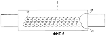
фиг.6 - двухрядная система смесительных сопел для нанесения смазочного средства на валок или прокатываемую полосу,6 is a two-row system of mixing nozzles for applying a lubricant to the roll or rolled strip,
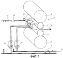
фиг.7 - прокатная клеть с масляно-водно-воздушной системой смазки с множеством трехкомпонентных смесительных сопел с газожидкостными распылителями и регулировочными клапанами для регулирования количества смазочного средства, приданными трехкомпонентным смесительным соплам, причем смазочное средство распыляется на верхний рабочий валок,7 is a rolling stand with an oil-water-air lubrication system with a plurality of three-component mixing nozzles with gas-liquid nozzles and control valves for controlling the amount of lubricant given to the three-component mixing nozzles, the lubricant being sprayed onto the upper work roll,
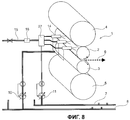
фиг.8 - прокатная клеть с масляно-водно-воздушной системой смазки, причем смазочное средство и газ перемешиваются в смесительном блоке и во множество двухкомпонентных смесительных сопел добавляется вода, а смазочное средство распыляется на верхний рабочий валок,Fig. 8 is a rolling stand with an oil-water-air lubrication system, wherein the lubricant and gas are mixed in the mixing unit and water is added to the plurality of two-component mixing nozzles, and the lubricant is sprayed onto the upper work roll,
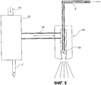
фиг.9 - продольный разрез смесительного блока на фиг.8 в сочетании с двухкомпонентным смесительным соплом, причем среды перемешиваются за пределами смесительного сопла,Fig.9 is a longitudinal section of the mixing block of Fig.8 in combination with a two-component mixing nozzle, and the medium is mixed outside the mixing nozzle,
фиг.10 - продольный разрез трехкомпонентного смесительного сопла для перемешивания воды, смазочного средства и газа со смесью жидких сред перед входом в пространство для сред,figure 10 is a longitudinal section of a three-component mixing nozzle for mixing water, lubricant and gas with a mixture of liquid media before entering the space for media,
фиг.11 - продольный разрез другого трехкомпонентного смесительного сопла для перемешивания воды, смазочного средства и газа со смесью жидких сред перед входом в пространство сред, причем все среды смешиваются в пространстве для сред,11 is a longitudinal section of another three-component mixing nozzle for mixing water, lubricant and gas with a mixture of liquid media before entering the media space, and all media are mixed in the media space,
фиг.12 - прокатная клеть с масляно-газовой системой смазки, причем смазочное средство и газ перемешиваются в смесительном блоке, смазочное средство распыляется на оба рабочих валка, а водораспылительные балки одновременно предусмотрены в качестве противопожарных устройств, и12 is a rolling stand with an oil-gas lubrication system, wherein the lubricant and gas are mixed in the mixing unit, the lubricant is sprayed onto both work rolls, and the spray beams are simultaneously provided as fire fighting devices, and
фиг.13 - прокатная клеть по фиг.7, причем дополнительно имеются измерительный ролик для измерения плоскостности и устройство для регулирования плоскостности.Fig.13 - rolling stand in Fig.7, and additionally there is a measuring roller for measuring flatness and a device for regulating flatness.
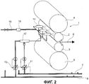
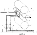
Прокатная клеть 1 (фиг.1) содержит два рабочих валка 2, 3, установленных между двумя опорными валками 4, 5 и прокатывающих прокатываемую полосу 6 (фиг.3). При этом сначала по отдельным подводящим трубопроводам 7, 8 и 9 подаются смазочное средство, в частности первое и второе масло или другие масла, а также вода. Прежде всего оба масла смешиваются. В порядке альтернативы используется также только одно или только другое масло. Желательные количества воды и обоих масел устанавливаются с помощью дозирующих насосов 10, 11 и закачиваются в смеситель 12. В результате, позади смесителя 12 из сведенных жидкостей образуется дисперсия или эмульсия. Расстояние между смесителем 12 и регулировочными клапанами 13, установленными в направлении потока, предпочтительно очень незначительно, или они во избежание расслоения смеси представляют собой единый блок. Регулировочные клапаны 13 распределены по всей ширине верхнего рабочего валка 2. Если нельзя обойтись без длинных трубопроводов, то в трубопроводе для придания турбулентности через определенные интервалы предусматриваются щитки (миксеры). Поперечное сечение трубопровода для реализации возможно большей скорости потока и тем самым малого времени транспортировки предпочтительно выбирается как можно меньшим. Для регулирования подачи смазочного средства по ширине рабочего валка 2, а также в зависимости от ширины обрабатываемой прокатываемой полосы 6 регулировочные клапаны 13 выдают смазочные средства в распылительные сопла 14, последовательно установленные в направлении потока и выполненные в виде двухкомпонентных смесительных сопел в соответствии с шириной прокатываемой полосы 6. В распылительных соплах 14 в водяную смесь со смазочным средством добавляется воздух, подводимый по трубопроводу 15 с помощью регулятора 16 давления для регулирования давления воздуха. Установка количеств смазочного средства или масла, а также воды осуществляется с помощью математической модели и/или регулирующего устройства, учитывающих различные смазочные свойства в зависимости от прокатываемого материала полосы, скорости, обжатия, температур и прочих параметров. Настройки регулировочных клапанов 13 и количества, закачиваемые дозирующими насосами 10, 11, согласуются друг с другом. Регулирующее устройство устанавливает концентрации смазочного средства или сорта смазывающих средств и, кроме того, осуществляет регулирование профиля и плоскостности прокатываемой полосы 6. В этом случае неровности прокатываемой полосы 6 компенсируются за счет подачи соответствующих количеств смазывающего средства или за счет изменения других параметров. При необходимости путем изменения количества, сорта, концентрации масла в воде и/или соотношения компонентов масла может быть оказано воздействие на уровень усилия прокатки.Rolling mill 1 (Fig. 1) contains two work rolls 2, 3, installed between two
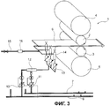
В упрощенном варианте выполнения прокатной клети 1 (фиг.2) регулировочные клапаны 13 отсутствуют. В этом случае расход распылительных сопел 14 устанавливается вручную, то есть является результатом регулировки дозирующего насоса. В другом варианте выполнения (фиг.3) водно-воздушная смесь со смазочным средством наносится непосредственно на нижнюю сторону прокатываемой полосы 6. Регулировочные клапаны 13 предусмотрены и в этом случае.In a simplified embodiment, the rolling stand 1 (figure 2)
В очередном варианте выполнения (фиг.4) вода, смазочное средство, например масло, и воздух вначале подаются по отдельным подводящим трубопроводам 7, 9, 15, а затем с помощью распылительных сопел 14 и 17, выполненных в виде трехкомпонентных сопел, наносятся на верхний рабочий валок 2, причем смешивание и распыление текучей среды составляют в распылительных соплах 17 единый блок. Однако и в этом случае предусмотрены регулирующие устройства, которые регулируют подачу соответствующей текучей среды в отдельные распылительные сопла 17 или в группу распылительных сопел. Предпочтительно, чтобы все отдельные регулирующие устройства были интегрированы в одну систему регулирования, определяющую объем и соотношение компонентов текучих сред, выдаваемых распылительными соплами 17 на рабочий валок 2 или на щиток 6 для придания турбулентности. Само собой разумеется, что во всех вариантах выполнения (фиг.1-4) предусмотрены или могут быть предусмотрены аналогичные варианты выполнения для подачи водно-воздушной смеси со смазочным средством на нижний рабочий валок 3 или на верхнюю сторону прокатываемой полосы 6.In a further embodiment (FIG. 4), water, a lubricant, for example oil, and air are first supplied through
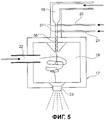
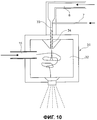
Распылительное сопло 17 (фиг.5) выполнено в виде барботерного сопла с внутренним смесителем с внутренним пространством 18, в которое с одной стороны по подводящему трубопроводу 19 подаются и в котором при необходимости, например, с помощью щитков 36 для придания турбулентности или сужения 37 трубопровода, перемешиваются вода и два смазочных средства. Процесс перемешивания жидкостей происходит незадолго до распыления. Смеситель и сопло здесь составляют единый блок. По двум трубопроводам 20, 21 сначала в трубопровод 19 непосредственно перед его выходом во внутреннее пространство 18 вводятся смазочные средства. Газ, в частности воздух, по первому трубопроводу 22 поступает во внутреннее пространство 18 и там завихряется со смесью воды с обоими смазочными средствами. Затем смесь конусообразно выходит из устья 23 сопла и попадает на поверхность валка или прокатываемой полосы 6. Поскольку смазочное средство (например, масло) или множество смазочных средств представляют собой важнейшую компоненту, в смысле изобретения индивидуально регулировать в каждом распылительном сопле 17 можно также только количество масла, а остальные компоненты регулируются групповым методом, то есть, например, на большом участке ширины валка и/или прокатываемой полосы 6. Нанесение смазочного средства или смазочных средств может осуществляться также без использования воды при исключительном использовании сжатого воздуха. В этом случае используется двухкомпонентное сопло.The spray nozzle 17 (Fig. 5) is made in the form of a bubbler nozzle with an internal mixer with an
Особенно при холодной прокатке важно, чтобы смазочная пленка полностью действовала по всей ширине прокатываемой полосы 6. Если смазочная пленка разрушится, то на поверхности появятся нежелательные царапины. Для обеспечения полноты действия смазки предпочтительно предусмотреть два или несколько рядов 24, 25 (фиг.6) распылительных сопел 17 напротив валка, например рабочего валка 2, или прокатываемой полосы, в которых распылительные сопла 17 предпочтительно установлены со смещением относительно друг друга. В качестве альтернативы может быть использована также однорядная распылительная балка, сопла которой имеют большой угол распыла, так что происходит двойное перекрытие. Это означает, что если одно сопло выпадет, то этот участок перекроют соседние сопла.Especially during cold rolling, it is important that the lubricating film fully acts across the entire width of the
По аналогии с вариантами выполнения, изображенными на фиг.1 и 3, в других вариантах выполнения изобретения имеются регулирующие устройства 26 (фиг.7), с помощью которых приток смазочного средства регулируется индивидуально в каждом распылительном сопле 14 по всей ширине полосы. Путем изменения количества воды и воздуха можно дополнительно воздействовать на всю смазку. При горячей прокатке смазочное средство подается по меньшей мере на один из рабочих валков 2, 3, при холодной прокатке смазочным средством обеспечивается предпочтительно прокатываемая полоса 6.By analogy with the embodiments depicted in FIGS. 1 and 3, in other embodiments of the invention there are control devices 26 (FIG. 7), by which the flow of lubricant is individually regulated in each
Согласно другому варианту (фиг.8) смазочное средство и воздух сводятся вместе в смесительном блоке 27. Воздух транспортирует смазочное средство к распылительным соплам 14. Каждое из сопел 14 питается по отдельности. Вода подается в сопла 14 отдельно.According to another embodiment (FIG. 8), the lubricant and air are brought together in the mixing
В смесительном блоке 27 (фиг.9) из трубопроводов 7 и 15 прежде всего сводятся вместе смазочное средство и воздух. Затем смесь из трубопровода 28 двухкомпонентного сопла 29 соединяется с водой, подаваемой из трубопровода 8. Двухкомпонентное сопло 29 выполнено как наружный смеситель. Это означает, что воздушная смесь со смазочным средством и вода сходятся лишь на выходе 30 сопла. Смешение обеспечивается в результате распыления двумя полыми конусами, образуемыми текучими средами, один в другой. Преимущество этого двухкомпонентного сопла 29 состоит в том, что омыление исключается, поскольку смазочное средство и вода приходят в соприкосновение друг с другом только на выходе 30 сопла. Для создания чистой смазки из смазочного средства с воздухом подачу воды можно исключить.In the mixing unit 27 (Fig. 9), the lubricant and the air are first brought together from the
В двухкомпонентном сопле 31 (фиг.10), выполненном как внутренний смеситель с внутренним пространством 32, вода и масло вначале вводятся во внутреннее пространство 32 по подводящему трубопроводу 33 совместно, а воздух - отдельно. В подводящем трубопроводе 33 для масла и воды в целях обеспечения перемешивания сред установлены щитки 34 для придания турбулентности или сопло Вентури.In a two-component nozzle 31 (Fig. 10), designed as an internal mixer with an
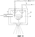
Трехкомпонентное сопло 35 (фиг.11) также имеет внутреннее пространство 32, в которое по трубопроводам 7, 8 и 15 раздельно подаются среды масла, воды и воздуха. Жидкие среды тем самым смешиваются лишь во внутреннем пространстве 32, распыляясь и разбрызгиваясь воздухом.The three-component nozzle 35 (Fig. 11) also has an
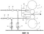
При желании использовать масляно-воздушную смесь без обязательной добавки к ней воды, то при горячей прокатке заботятся о противопожарной защите, для чего при необходимости с помощью водораспылительных балок 38, 39 (фиг.12) создается водяная завеса, защищающая масляно--воздушную смесь снаружи. Дополнительно вокруг масляно-воздушного тумана, создаваемого распылительными соплами 14, предусмотрены защитные стенки 40, 41. Масляно-воздушный туман может отсасываться снаружи. Для улучшения защиты и обеспечения установки сопел впереди валка вплотную к ним защитные стенки 40, 41, а также распылительные балки 14 выполняются с возможностью поворота. Примерно такой же отсос предусмотрен также при нанесении смазочного средства на прокатываемую полосу (при холодной прокатке).If you want to use the oil-air mixture without the obligatory addition of water to it, then hot rolling takes care of fire protection, for which, if necessary, a water curtain is created using water spray beams 38, 39 (Fig. 12) to protect the oil-air mixture from the outside . Additionally, around the oil-air fog generated by the
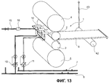
Для оказания воздействия на поверхностную структуру (плоскостность, равномерность состояния натяжения) прокатываемой полосы 6 в очередном варианте выполнения изобретения предусмотрены мерный ролик 42 (фиг.13) для измерения плоскостности или какое-либо иное бесконтактное (оптическое) измерение плоскостности для определения неровностей прокатываемой полосы 6, при которых сигналы передаются по сигнальному проводу 43 в (не показанное здесь) устройство обработки данных. В нем формируются сигналы регулирования или управления распылительными соплами 14 или регулировочными клапанами 13 для выдачи соответствующих количеств смазочного средства на рабочий валок 2 по ширине полосы. С помощью количества смазочного средства, отпущенного в расчете на одну зону, или концентрации смазочного средства поддается воздействию плоскостность полосы параболического типа или высшего порядка. Само собой разумеется, что соответствующее регулирование может быть установлено также в отношении нижнего рабочего валка 3. Точно так же для оказания воздействия на плоскостность полосы и распределение натяжения полосы по ее ширине распылительные сопла 14 могут распылять смазочное средство и непосредственно на прокатываемую полосу 6.In order to influence the surface structure (flatness, uniformity of the tension state) of the rolled
Перечень позицийList of items
1. Прокатная клеть1. Rolling stand
2. Рабочий валок2. Work roll
3. Рабочий валок3. Work roll
4. Опорный валок4. Back-up roll
5. Опорный валок5. Back-up roll
6. Прокатываемая полоса6. Rolled strip
7. Подводящий трубопровод7. Supply pipe
8. Подводящий трубопровод8. Supply pipe
9. Подводящий трубопровод9. Supply pipe
10. Дозирующий насос10. Dosing pump
11. Дозирующий насос11. Dosing pump
12. Смеситель12. Mixer
13. Регулировочный клапан13. Control valve
14. Распылительные сопла (многокомпонентные сопла)14. Spray nozzles (multi-component nozzles)
15. Трубопровод15. The pipeline
16. Регулятор давления16. Pressure regulator
17. Распылительные сопла (многокомпонентные сопла)17. Spray nozzles (multi-component nozzles)
18. Внутреннее пространство18. Interior space
19. Подводящий трубопровод19. Supply pipe
20. Трубопровод20. The pipeline
21. Трубопровод21. The pipeline
22. Подводящий трубопровод22. Supply pipe
23. Устье сопла23. The mouth of the nozzle
24. Ряд24. Row
25. Ряд25. Row
26. Регулирующие устройства26. Regulatory devices
27. Смесительный блок27. Mixing unit
28. Трубопровод28. Pipeline
29. Многокомпонентное сопло29. Multi-component nozzle
30. Выход сопла30. Nozzle exit
31. Многокомпонентное сопло31. Multi-component nozzle
32. Внутреннее пространство32. Interior space
33. Подводящий трубопровод33. Inlet pipe
34. Щиток для придания турбулентности34. Shield for imparting turbulence
35. Многокомпонентное сопло35. Multi-component nozzle
36. Щиток для придания турбулентности36. Shield for imparting turbulence
37. Сужение трубопровода37. The narrowing of the pipeline
38. Распылительная балка38. Spray beam
39. Распылительная балка39. Spray beam
40. Стенка40. Wall
41. Стенка41. The wall
42. Измерительный ролик для измерения плоскостности42. Measuring roller for measuring flatness
43. Сигнальный провод43. Signal wire
Claims (25)
Applications Claiming Priority (5)
| Application Number | Priority Date | Filing Date | Title |
|---|---|---|---|
| DE102008028620.6 | 2008-06-18 | ||
| DE102008028620 | 2008-06-18 | ||
| DE102008034099.5 | 2008-07-21 | ||
| DE102008034099 | 2008-07-21 | ||
| DE102008050392.4 | 2008-10-02 |
Publications (2)
| Publication Number | Publication Date |
|---|---|
| RU2011101567A RU2011101567A (en) | 2012-07-27 |
| RU2463118C2 true RU2463118C2 (en) | 2012-10-10 |
Family
ID=41335046
Family Applications (1)
| Application Number | Title | Priority Date | Filing Date |
|---|---|---|---|
| RU2011101567/02A RU2463118C2 (en) | 2008-06-18 | 2009-06-09 | Method and device for lubing rolls and rolled strip in mill stand |
Country Status (15)
| Country | Link |
|---|---|
| US (2) | US9254513B2 (en) |
| EP (1) | EP2303480B1 (en) |
| JP (2) | JP2011524257A (en) |
| KR (1) | KR101249255B1 (en) |
| CN (1) | CN102083559A (en) |
| AU (1) | AU2009262567B2 (en) |
| BR (1) | BRPI0915298A8 (en) |
| CA (1) | CA2728197C (en) |
| DE (1) | DE102008050392A1 (en) |
| MX (1) | MX2010013881A (en) |
| RU (1) | RU2463118C2 (en) |
| TW (2) | TWM513070U (en) |
| UA (1) | UA100275C2 (en) |
| WO (1) | WO2009156057A2 (en) |
| ZA (1) | ZA201008619B (en) |
Cited By (3)
| Publication number | Priority date | Publication date | Assignee | Title |
|---|---|---|---|---|
| RU2623788C2 (en) * | 2015-09-11 | 2017-06-29 | Николай Викторович Мендрух | Method of geartrain lubrication |
| RU2675413C2 (en) * | 2014-01-08 | 2018-12-19 | Прайметалз Текнолоджиз Аустриа ГмбХ | Lubrication using spray nozzles having multiple oil inlet openings |
| EA032995B1 (en) * | 2017-08-28 | 2019-08-30 | Александр Сергеевич ИВАНОВ | Method for removal of a polymer film roll wound without a core from a mandrel |
Families Citing this family (29)
| Publication number | Priority date | Publication date | Assignee | Title |
|---|---|---|---|---|
| DE102008050392A1 (en) * | 2008-06-18 | 2009-12-24 | Sms Siemag Aktiengesellschaft | Method and device for lubricating rolls and a rolled strip of a roll stand |
| AR076167A1 (en) * | 2009-03-30 | 2011-05-26 | Sumitomo Metal Ind | APPLIANCE AND METHOD FOR THE APPLICATION OF A LUBRICANT TO A THREADED PORTION OF A STEEL PIPE |
| BR112012025589B1 (en) * | 2010-04-07 | 2021-05-25 | Nippon Steel Corporation | equipment and method of providing lubricant |
| EP2465619A1 (en) * | 2010-12-16 | 2012-06-20 | Siemens VAI Metals Technologies GmbH | Method and device for applying a lubricant when milling a metallic milling product |
| EP2489446A1 (en) | 2011-02-17 | 2012-08-22 | Linde Aktiengesellschaft | Nozzle header |
| RU2630078C2 (en) * | 2012-02-15 | 2017-09-05 | Прайметалз Текнолоджиз Аустриа ГмбХ | Low maintenance mixing nozzle for lubricating gap between rollers |
| US9643206B2 (en) * | 2013-09-20 | 2017-05-09 | Nabors Industries, Inc. | Lubricant application to threaded pipe connections |
| CN104907338B (en) * | 2014-03-12 | 2017-01-04 | 中冶南方工程技术有限公司 | Hot rolling roll gap lubricating arrangement and method |
| PL3140057T5 (en) * | 2014-05-09 | 2023-02-27 | Novelis, Inc. | Hybrid oil and water cooled rolling |
| CN105363785A (en) * | 2014-08-28 | 2016-03-02 | 张丹嫣 | Cooling system for dual-roller rolling mill |
| DE102014224318A1 (en) * | 2014-11-27 | 2016-06-02 | Sms Group Gmbh | Apparatus and method for cooling a roll |
| US9851041B2 (en) * | 2015-03-04 | 2017-12-26 | Emagineered Solutions, Inc. | Tubing everting apparatus, assemblies, and methods |
| CN104985009B (en) * | 2015-07-31 | 2017-08-01 | 张正秀 | A kind of cold rolling use lubricating utensil of metal plate and belt, lubricating method and ROLLING OIL |
| RU2717626C1 (en) | 2017-02-28 | 2020-03-24 | ДжФЕ СТИЛ КОРПОРЕЙШН | Cold rolling mill and cold rolling method |
| CN107497860A (en) * | 2017-08-22 | 2017-12-22 | 苏州双金实业有限公司 | A kind of processing method that can improve stainless Steel Properties |
| CN109550790B (en) * | 2017-09-27 | 2020-06-23 | 宝山钢铁股份有限公司 | Emulsion spraying control method and spraying device of secondary cold rolling unit |
| CN108160713A (en) * | 2018-01-18 | 2018-06-15 | 上海利正卫星应用技术有限公司 | Roll grease lubrication system and method during magnesium alloy rolling |
| CA3091392A1 (en) * | 2018-06-13 | 2019-12-19 | Novelis Inc. | Hybrid rolling mill |
| CN108723092A (en) * | 2018-06-20 | 2018-11-02 | 北京首钢股份有限公司 | A kind of device for the edger roll surface quality improving vertical miller |
| CN108722713A (en) * | 2018-08-11 | 2018-11-02 | 张家港保税区宇联羊毛工业有限公司 | The injection apparatus of wool opener |
| KR102109262B1 (en) * | 2018-08-16 | 2020-05-11 | 주식회사 포스코 | Lubricating apparatus |
| CN109396198B (en) * | 2018-11-14 | 2023-09-19 | 浙江中达新材料股份有限公司 | Cold-rolled tube device with automatic oiling function |
| CN109622617B (en) * | 2018-12-07 | 2020-06-16 | 温州曼昔维服饰有限公司 | Rolling roller assembly |
| CN109622616B (en) * | 2018-12-07 | 2020-06-12 | 长乐巧通工业设计有限公司 | Rolling equipment |
| US20200235825A1 (en) * | 2019-01-22 | 2020-07-23 | Interlock Concepts Inc. | Panic alerts using ultrasonic sound waves |
| CN110355215B (en) * | 2019-05-29 | 2021-12-07 | 科芃智能科技(苏州)有限公司 | Strip edge plate type control method and system based on induction heating |
| CN110170531B (en) * | 2019-06-19 | 2021-04-20 | 鞍钢未来钢铁研究院有限公司 | Lubricating method for rolling section bar |
| DE102020130265A1 (en) * | 2020-11-17 | 2022-05-19 | Harburg-Freudenberger Maschinenbau Gmbh | Roller system, use of a wetting device and method for operating a roller system |
| CN113083892B (en) * | 2021-03-29 | 2022-07-08 | 天津市新天钢联合特钢有限公司 | Preparation method of hot-rolled narrow strip steel for gas pipeline |
Citations (5)
| Publication number | Priority date | Publication date | Assignee | Title |
|---|---|---|---|---|
| SU1579594A1 (en) * | 1988-03-30 | 1990-07-23 | Магнитогорский металлургический комбинат им.В.И.Ленина | Method of preparing lubricant for feeding to rolls in hot rolling |
| US5090225A (en) * | 1988-10-18 | 1992-02-25 | Sms Schloemann-Siemag Aktiengesellschaft | Method for cooling and lubricating chiplessly shaped metals |
| WO2003000437A1 (en) * | 2001-06-23 | 2003-01-03 | Sms Demag Aktiengesellschaft | Method and nozzle arrangement for a variable-width lubrication of the rolling nip of a rolling stand |
| DE102005042020A1 (en) * | 2005-09-02 | 2007-03-08 | Sms Demag Ag | Method for lubricating and cooling rolls and metal strip during rolling, in particular during cold rolling, of metal strips |
| EP1829625A1 (en) * | 2004-11-22 | 2007-09-05 | Nippon Steel Corporation | Method for supplying lubricating oil in cold rolling |
Family Cites Families (47)
| Publication number | Priority date | Publication date | Assignee | Title |
|---|---|---|---|---|
| US3301029A (en) * | 1964-07-06 | 1967-01-31 | Reynolds Metals Co | Working aluminous metals |
| US3763679A (en) * | 1969-05-29 | 1973-10-09 | Us Corp | Apparatus for applying lubricant to a workpiece in a hot strip mill |
| AU450187B2 (en) * | 1970-09-25 | 1974-07-04 | Uss Engineers And Consultants, Inc | Method of lubricating a hot steel workpiece prior to hot rolling |
| US4038570A (en) * | 1974-03-20 | 1977-07-26 | Durley Iii Benton A | Ultrasonic piezoelectric transducer drive circuit |
| US4085893A (en) * | 1974-03-20 | 1978-04-25 | Durley Iii Benton A | Ultrasonic humidifiers, atomizers and the like |
| SU869881A1 (en) | 1979-05-25 | 1981-10-10 | Донецкий научно-исследовательский институт черной металлургии | Method of producing and feeding technological lubracant on rolling mill rolls |
| JPS5742362A (en) * | 1980-08-22 | 1982-03-09 | Ikeuchi:Kk | Atomized spray generator |
| JPS58159910A (en) | 1982-03-19 | 1983-09-22 | Sumitomo Metal Ind Ltd | Controlling method for shape of hot strip |
| JPS59118211A (en) | 1982-12-22 | 1984-07-07 | Sumitomo Metal Ind Ltd | Method for controlling flatness of rolling material |
| US4510784A (en) * | 1983-10-11 | 1985-04-16 | Kaiser Aluminum & Chemical Corporation | Rolling mill spray bar |
| JPS60238014A (en) | 1984-05-10 | 1985-11-26 | Mitsubishi Electric Corp | Shape control method for rolling mill |
| DE3419261C3 (en) | 1984-05-23 | 1994-12-15 | Achenbach Buschhuetten Gmbh | Roll cooling and / or lubricating device for cold strip rolling mills, especially fine strip rolling mills |
| NL8502651A (en) * | 1985-09-27 | 1987-04-16 | Airspray Int Bv | Atomizer for a container for a liquid to be atomized. |
| JP2718520B2 (en) | 1988-09-26 | 1998-02-25 | フロイント産業株式会社 | Spray nozzle and granulation coding device using the same |
| JPH038510A (en) | 1989-06-06 | 1991-01-16 | Sumitomo Light Metal Ind Ltd | Method of lubrication in hot rolling for aluminum |
| US5129482A (en) * | 1990-09-13 | 1992-07-14 | A.W. Chesterton Company | Closed lubrication system for bearings |
| US5286348A (en) * | 1991-10-16 | 1994-02-15 | Valmet Automation (Canada) Ltd. | Electronic flow modulated cross direction moisture actuator |
| DE4306093C2 (en) * | 1993-02-27 | 1996-08-22 | Chiron Werke Gmbh | Machine tool with splash protection walls |
| US5916625A (en) * | 1993-04-08 | 1999-06-29 | Ppg Industries, Inc. | Method and apparatus for spraying waterborne coatings under varying conditions |
| US5692682A (en) * | 1995-09-08 | 1997-12-02 | Bete Fog Nozzle, Inc. | Flat fan spray nozzle |
| JP3103825B2 (en) | 1996-08-22 | 2000-10-30 | 住友金属工業株式会社 | Method and apparatus for temper rolling of steel strip |
| DE19820432A1 (en) * | 1998-05-07 | 1999-11-11 | Voith Sulzer Papiertech Patent | Method and device for applying an application medium to a running surface |
| US6602554B1 (en) * | 2000-01-14 | 2003-08-05 | Illinois Tool Works Inc. | Liquid atomization method and system |
| DE20006508U1 (en) | 2000-04-08 | 2000-08-31 | Achenbach Buschhuetten Gmbh | Roller cooling and / or lubricating device for cold strip rolling mills, in particular fine strip and foil rolling mills |
| FI111054B (en) * | 2001-06-25 | 2003-05-30 | Vesa Antero Koponen | Nozzle for coating surfaces |
| DE10131369A1 (en) * | 2001-06-28 | 2003-01-09 | Sms Demag Ag | Method and device for cooling and lubricating rolls of a roll stand |
| JP4123865B2 (en) | 2002-08-12 | 2008-07-23 | 株式会社Ihi | Pinch roll lubrication mist sprayer |
| JP2006142339A (en) * | 2004-11-19 | 2006-06-08 | Nippon Steel Corp | Method for supplying lubricant in hot rolling |
| JP4654719B2 (en) | 2005-03-18 | 2011-03-23 | Jfeスチール株式会社 | Method and apparatus for supplying rolling oil in cold rolling |
| JP2006263740A (en) | 2005-03-22 | 2006-10-05 | Nippon Steel Corp | Method and apparatus for supplying lubricating oil in cold rolling |
| JP2006263741A (en) | 2005-03-22 | 2006-10-05 | Nippon Steel Corp | Method of supplying lubricating oil in cold rolling |
| JP4640157B2 (en) | 2005-12-15 | 2011-03-02 | Jfeスチール株式会社 | Cold rolling method and apparatus |
| JP4609893B2 (en) * | 2006-02-02 | 2011-01-12 | 大同メタル工業株式会社 | Tool holder |
| JP4715564B2 (en) | 2006-03-08 | 2011-07-06 | Jfeスチール株式会社 | Cold rolling method |
| JP4797730B2 (en) | 2006-03-22 | 2011-10-19 | Jfeスチール株式会社 | Cold rolling method |
| GB0625583D0 (en) * | 2006-12-21 | 2007-01-31 | Itw Ltd | Paint spray apparatus |
| DE102007042898A1 (en) * | 2007-06-08 | 2008-12-11 | Sms Demag Ag | Method and device for roller lubrication |
| US9272297B2 (en) * | 2008-03-04 | 2016-03-01 | Sono-Tek Corporation | Ultrasonic atomizing nozzle methods for the food industry |
| DE102008050392A1 (en) * | 2008-06-18 | 2009-12-24 | Sms Siemag Aktiengesellschaft | Method and device for lubricating rolls and a rolled strip of a roll stand |
| US20100224122A1 (en) * | 2009-03-09 | 2010-09-09 | Illinois Tool Works Inc. | Low pressure regulation for web moistening systems |
| US9186881B2 (en) * | 2009-03-09 | 2015-11-17 | Illinois Tool Works Inc. | Thermally isolated liquid supply for web moistening |
| US20100224703A1 (en) * | 2009-03-09 | 2010-09-09 | Illinois Tool Works Inc. | Pneumatic Atomization Nozzle for Web Moistening |
| US8979004B2 (en) * | 2009-03-09 | 2015-03-17 | Illinois Tool Works Inc. | Pneumatic atomization nozzle for web moistening |
| BR112012025589B1 (en) * | 2010-04-07 | 2021-05-25 | Nippon Steel Corporation | equipment and method of providing lubricant |
| EP2465619A1 (en) * | 2010-12-16 | 2012-06-20 | Siemens VAI Metals Technologies GmbH | Method and device for applying a lubricant when milling a metallic milling product |
| CA2784109C (en) * | 2012-07-27 | 2019-06-18 | Nex Flow Air Products Corp. | Apparatus and method for cooling and lubrication |
| EP2969278B1 (en) * | 2013-03-15 | 2017-08-02 | Novelis, Inc. | Manufacturing methods and apparatus for targeted lubrication in hot metal rolling |
-
2008
- 2008-10-02 DE DE102008050392A patent/DE102008050392A1/en not_active Withdrawn
-
2009
- 2009-06-09 BR BRPI0915298A patent/BRPI0915298A8/en not_active Application Discontinuation
- 2009-06-09 RU RU2011101567/02A patent/RU2463118C2/en not_active IP Right Cessation
- 2009-06-09 EP EP09768906.1A patent/EP2303480B1/en active Active
- 2009-06-09 AU AU2009262567A patent/AU2009262567B2/en not_active Ceased
- 2009-06-09 TW TW102222435U patent/TWM513070U/en not_active IP Right Cessation
- 2009-06-09 TW TW098119138A patent/TW201012563A/en unknown
- 2009-06-09 JP JP2011513919A patent/JP2011524257A/en active Pending
- 2009-06-09 MX MX2010013881A patent/MX2010013881A/en active IP Right Grant
- 2009-06-09 CN CN2009801231161A patent/CN102083559A/en active Pending
- 2009-06-09 KR KR1020107029233A patent/KR101249255B1/en active IP Right Grant
- 2009-06-09 WO PCT/EP2009/004138 patent/WO2009156057A2/en active Application Filing
- 2009-06-09 CA CA2728197A patent/CA2728197C/en not_active Expired - Fee Related
- 2009-06-09 US US13/000,281 patent/US9254513B2/en not_active Expired - Fee Related
- 2009-09-06 UA UAA201100446A patent/UA100275C2/en unknown
-
2010
- 2010-12-01 ZA ZA2010/08619A patent/ZA201008619B/en unknown
-
2013
- 2013-11-13 US US14/079,244 patent/US20140060135A1/en not_active Abandoned
- 2013-12-04 JP JP2013251058A patent/JP2014061550A/en active Pending
Patent Citations (5)
| Publication number | Priority date | Publication date | Assignee | Title |
|---|---|---|---|---|
| SU1579594A1 (en) * | 1988-03-30 | 1990-07-23 | Магнитогорский металлургический комбинат им.В.И.Ленина | Method of preparing lubricant for feeding to rolls in hot rolling |
| US5090225A (en) * | 1988-10-18 | 1992-02-25 | Sms Schloemann-Siemag Aktiengesellschaft | Method for cooling and lubricating chiplessly shaped metals |
| WO2003000437A1 (en) * | 2001-06-23 | 2003-01-03 | Sms Demag Aktiengesellschaft | Method and nozzle arrangement for a variable-width lubrication of the rolling nip of a rolling stand |
| EP1829625A1 (en) * | 2004-11-22 | 2007-09-05 | Nippon Steel Corporation | Method for supplying lubricating oil in cold rolling |
| DE102005042020A1 (en) * | 2005-09-02 | 2007-03-08 | Sms Demag Ag | Method for lubricating and cooling rolls and metal strip during rolling, in particular during cold rolling, of metal strips |
Cited By (3)
| Publication number | Priority date | Publication date | Assignee | Title |
|---|---|---|---|---|
| RU2675413C2 (en) * | 2014-01-08 | 2018-12-19 | Прайметалз Текнолоджиз Аустриа ГмбХ | Lubrication using spray nozzles having multiple oil inlet openings |
| RU2623788C2 (en) * | 2015-09-11 | 2017-06-29 | Николай Викторович Мендрух | Method of geartrain lubrication |
| EA032995B1 (en) * | 2017-08-28 | 2019-08-30 | Александр Сергеевич ИВАНОВ | Method for removal of a polymer film roll wound without a core from a mandrel |
Also Published As
| Publication number | Publication date |
|---|---|
| KR20110011713A (en) | 2011-02-08 |
| DE102008050392A1 (en) | 2009-12-24 |
| EP2303480A2 (en) | 2011-04-06 |
| WO2009156057A2 (en) | 2009-12-30 |
| UA100275C2 (en) | 2012-12-10 |
| BRPI0915298A2 (en) | 2016-07-05 |
| JP2014061550A (en) | 2014-04-10 |
| TW201012563A (en) | 2010-04-01 |
| US20140060135A1 (en) | 2014-03-06 |
| BRPI0915298A8 (en) | 2018-10-23 |
| KR101249255B1 (en) | 2013-04-09 |
| RU2011101567A (en) | 2012-07-27 |
| ZA201008619B (en) | 2011-08-31 |
| US20110111124A1 (en) | 2011-05-12 |
| WO2009156057A3 (en) | 2010-02-18 |
| TWM513070U (en) | 2015-12-01 |
| CA2728197C (en) | 2013-10-15 |
| MX2010013881A (en) | 2011-01-20 |
| AU2009262567B2 (en) | 2012-06-14 |
| CN102083559A (en) | 2011-06-01 |
| JP2011524257A (en) | 2011-09-01 |
| US9254513B2 (en) | 2016-02-09 |
| AU2009262567A1 (en) | 2009-12-30 |
| CA2728197A1 (en) | 2009-12-30 |
| EP2303480B1 (en) | 2013-06-05 |
Similar Documents
| Publication | Publication Date | Title |
|---|---|---|
| RU2463118C2 (en) | Method and device for lubing rolls and rolled strip in mill stand | |
| JP2011524257A5 (en) | ||
| AU2002317793B2 (en) | Method and nozzle arrangement for a variable-width lubrication of the rolling nip of a rolling stand | |
| TWI420038B (en) | Lubricating oil supply equipment and lubricating oil supply method | |
| CN101821026A (en) | The atomized lubrication equipment and the method for roll | |
| US20080257647A1 (en) | Apparatus and Method for Supplying Lubricant in Endless Hot Rolling Equipment | |
| AU643729B2 (en) | The rolling of metal strip | |
| JP2006263741A (en) | Method of supplying lubricating oil in cold rolling | |
| JP6350274B2 (en) | Lubricating oil supply equipment for cold rolling mills | |
| JP4962055B2 (en) | Cold rolling method and cold rolling apparatus | |
| SU1088835A1 (en) | Apparatus for gas and liquid machining of rolled stock |
Legal Events
| Date | Code | Title | Description |
|---|---|---|---|
| MM4A | The patent is invalid due to non-payment of fees |
Effective date: 20200610 |