RU2460607C2 - Device and method for subsequent casting of metals having equal or similar shrinkage factors - Google Patents
Device and method for subsequent casting of metals having equal or similar shrinkage factors Download PDFInfo
- Publication number
- RU2460607C2 RU2460607C2 RU2010108668/02A RU2010108668A RU2460607C2 RU 2460607 C2 RU2460607 C2 RU 2460607C2 RU 2010108668/02 A RU2010108668/02 A RU 2010108668/02A RU 2010108668 A RU2010108668 A RU 2010108668A RU 2460607 C2 RU2460607 C2 RU 2460607C2
- Authority
- RU
- Russia
- Prior art keywords
- metal
- angle
- mold
- dividing wall
- casting
- Prior art date
Links
Images

Classifications
-
- B—PERFORMING OPERATIONS; TRANSPORTING
- B22—CASTING; POWDER METALLURGY
- B22D—CASTING OF METALS; CASTING OF OTHER SUBSTANCES BY THE SAME PROCESSES OR DEVICES
- B22D11/00—Continuous casting of metals, i.e. casting in indefinite lengths
- B22D11/007—Continuous casting of metals, i.e. casting in indefinite lengths of composite ingots, i.e. two or more molten metals of different compositions being used to integrally cast the ingots
Abstract
Description
Область техники, к которой относится изобретениеFIELD OF THE INVENTION
Изобретение относится к литью металлов, в частности алюминия и алюминиевых сплавов способом литья с прямым охлаждением. Точнее изобретение относится к совместному литью слоев металла способом литья с прямым охлаждением, включающим в себя последовательную кристаллизацию.The invention relates to the casting of metals, in particular aluminum and aluminum alloys, by direct cooling casting. More precisely, the invention relates to the joint casting of metal layers by a direct cooling casting method, including sequential crystallization.
Уровень техникиState of the art
Металлические слитки обычно получают способом литья расплавленных металлов с прямым охлаждением. Способ заключается в заливке расплавленного металла в кристаллизатор с охлажденными стенками, у которого имеется открытая верхняя сторона и открытая (после начала процесса) нижняя сторона. Расплавленный металл с открытой верхней стороны вводят в кристаллизатор, где металл, проходя через кристаллизатор, охлаждается и кристаллизуется (по меньшей мере, снаружи). Кристаллизовавшийся металл появляется с нижней стороны кристаллизатора в виде металлического слитка, который опускается по мере осуществления процесса литья. В иных случаях литье производится горизонтально, но по сути процесс литья одинаков. Такие способы литья пригодны, в частности, для литья алюминия и алюминиевых сплавов, но они подходят также для литья и других металлов.Metal ingots are usually produced by direct-cooling molten metal casting. The method consists in pouring molten metal into a crystallizer with cooled walls, which has an open upper side and an open (after the start of the process) lower side. The molten metal from the open upper side is introduced into the mold, where the metal, passing through the mold, is cooled and crystallized (at least from the outside). Crystallized metal appears on the bottom side of the mold in the form of a metal ingot, which is lowered as the casting process proceeds. In other cases, the casting is done horizontally, but in fact the casting process is the same. Such casting methods are suitable, in particular, for casting aluminum and aluminum alloys, but they are also suitable for casting and other metals.
Приемы литья такого вида широко обсуждаются в патенте США 6260602 (Wagstaff), который касается исключительно получения монолитных слитков, т.е. слитков, выполненных из одного и того же материала по всему слитку, в виде одного слоя. Аппараты и способы для получения многослойных структур литьем с последовательной кристаллизацией раскрыты, например, в патентной публикации США 2005/0011630 А1 (Anderson и др.). Литье с последовательной кристаллизацией включает в себя литье первого слоя, а затем, следующим шагом, но в пределах одной и той же литейной операции, литье слоя другого металла на первый слой, после того как он достигнет надлежащей степени затвердевания. Существуют варианты, при которых вначале в многослойном слитке производят литье наружных слоев, а затем выполняют литье срединного слоя внутрь наружных слоев, как только произойдет их надлежащее затвердевание.Casting techniques of this kind are widely discussed in US Pat. No. 6,260,602 (Wagstaff), which deals exclusively with the production of monolithic ingots, i.e. ingots made of the same material throughout the ingot, in the form of a single layer. Apparatuses and methods for producing multilayer structures by casting with sequential crystallization are disclosed, for example, in US Patent Publication 2005/0011630 A1 (Anderson et al.). Sequential crystallization casting involves casting the first layer, and then, in the next step, but within the same casting operation, casting a layer of another metal onto the first layer after it reaches the proper degree of solidification. There are options in which the outer layers are first casted in the multilayer ingot, and then the middle layer is cast into the outer layers as soon as they have solidified properly.
Хотя указанные способы эффективны и с успехом применяются, установлено, что могут возникать трудности при попытке использовать способ последовательной кристаллизации с определенными сочетаниями сплавов, в частности с теми, которые имеют одинаковые или очень близкие коэффициенты усадки при кристаллизации и охлаждении. В частности, установлено, что, когда производится последовательное литье таких металлов, то может не достигаться требуемая прочность связывания покрывающего слоя (оболочки) с базовым (срединным) слоем, особенно, в центральной зоне составного слитка.Although these methods are effective and successfully applied, it was found that difficulties may arise when trying to use a sequential crystallization method with certain combinations of alloys, in particular with those that have the same or very close shrink coefficients during crystallization and cooling. In particular, it was found that when sequential casting of such metals is carried out, the required bond strength of the coating layer (shell) with the base (middle) layer may not be achieved, especially in the central zone of the composite ingot.
Следовательно, существует необходимость усовершенствования литейного оборудования и способов совместного литья таких металлов.Therefore, there is a need to improve foundry equipment and methods for co-casting such metals.
Раскрытие изобретенияDisclosure of invention
Согласно одному варианту осуществления изобретения предлагается установка для литья составного металлического слитка. Установка содержит сквозную формообразующую полость кристаллизатора, которая, в целом, имеет прямоугольное сечение и содержит входную часть, выпускное отверстие и подвижный нижний блок, выполненный с возможностью посадки в выпускное отверстие и перемещения вдоль оси кристаллизатора в процессе литья. Во входной части кристаллизатора предусмотрена, по меньшей мере, одна охлаждаемая разделительная перегородка для разделения входной части, по меньшей мере, на две камеры подачи металла. Установка включает в себя подающее устройство для подвода металла для внутреннего слоя к одной из указанных, по меньшей мере, двух камер подачи металла, и, по меньшей мере, одно дополнительное подающее устройство для подвода металла, по меньшей мере, для одного наружного слоя, по меньшей мере, к одной другой из указанных камер подачи металла. Указанная, по меньшей мере, одна разделительная перегородка имеет поверхность контакта с металлом, которая при работе кристаллизатора соприкасается с металлом, по меньшей мере, одного наружного слоя, причем указанная поверхность наклонена под углом от металла наружного слоя в направлении течения металла через кристаллизатор, при этом в средней части указанной, по меньшей мере, одной разделительной перегородки указанный угол наклона больше, чем в местах, примыкающих к концам, по меньшей мере, одной разделительной перегородки.According to one embodiment of the invention, there is provided an apparatus for casting a composite metal ingot. The installation contains a through mold cavity of the mold, which, in general, has a rectangular cross section and contains an inlet, an outlet and a movable lower unit configured to fit into the outlet and move along the axis of the mold during casting. At least one cooled dividing wall is provided in the inlet part of the mold for dividing the inlet part into at least two metal feed chambers. The installation includes a feeding device for supplying metal for the inner layer to one of the at least two metal supply chambers, and at least one additional feeding device for supplying metal for at least one outer layer, at least one other of these metal feed chambers. The specified at least one dividing wall has a contact surface with a metal that, when the mold is in operation, is in contact with the metal of at least one outer layer, said surface inclined at an angle from the metal of the outer layer in the direction of metal flow through the mold, in the middle part of the specified at least one dividing wall, the specified angle of inclination is greater than in places adjacent to the ends of the at least one dividing wall.
Согласно другому варианту осуществления изобретения предлагается способ литья составного слитка, содержащий этапы, на которых: подготавливают установку для литья составного металлического слитка, включающую в себя сквозную формообразующую полость кристаллизатора, которая, в целом, имеет прямоугольное сечение и содержит входную часть, выпускное отверстие и подвижный нижний блок, выполненный с возможностью посадки в выпускное отверстие и перемещения вдоль оси кристаллизатора в процессе литья, по меньшей мере, одну охлаждаемую разделительную перегородку во входной части кристаллизатора для разделения входной части, по меньшей мере, на две камеры подачи металла, и подающее устройство для подвода металла для внутреннего слоя к одной из указанных, по меньшей мере, двух камер подачи металла, и, по меньшей мере, одно дополнительное подающее устройство для подвода металла, по меньшей мере, для одного наружного слоя, по меньшей мере, к одной другой из указанных камер подачи металла, при этом указанная, по меньшей мере, одна разделительная перегородка имеет поверхность контакта с металлом, которая при работе кристаллизатора соприкасается с металлом, по меньшей мере, одного наружного слоя, причем указанная поверхность наклонена под углом от металла наружного слоя в направлении течения металла через кристаллизатор, при этом в средней части указанной, по меньшей мере, одной разделительной перегородки указанный угол наклона больше, чем в местах, примыкающих к концам, по меньшей мере, одной разделительной перегородки; подают металл для внутреннего слоя в одну из указанных, по меньшей мере, двух камер подачи металла; подают металл, по меньшей мере, для одного наружного слоя, по меньшей мере, в одну другую из указанных камер подачи металла, причем металл для внутреннего слоя и металл, по меньшей мере, для одного наружного слоя выбирают так, чтобы указанные металлы имели равные или близкие коэффициенты усадки; и перемещают нижний блок вдоль оси кристаллизатора, чтобы слиток имел возможность выхода из выпускного отверстия установки.According to another embodiment of the invention, there is provided a method for casting a composite ingot, comprising the steps of: preparing an installation for casting a composite metal ingot, including a through mold cavity of the mold, which generally has a rectangular cross section and contains an inlet, an outlet and a movable the lower block, made with the possibility of landing in the outlet and moving along the axis of the mold during the casting process, at least one cooled section a baffle plate in the inlet part of the mold for dividing the inlet part into at least two metal supply chambers, and a metal supply device for supplying the inner layer to one of the at least two metal supply chambers, and at least one additional supply device for supplying metal for at least one outer layer to at least one other of said metal supply chambers, wherein said at least one dividing wall has a contact surface metal, which, when the mold is in operation, is in contact with the metal of at least one outer layer, said surface being inclined at an angle from the metal of the outer layer in the direction of metal flow through the mold, while in the middle part of said at least one dividing wall, the angle of inclination is greater than in places adjacent to the ends of at least one dividing wall; supplying metal for the inner layer to one of said at least two metal supply chambers; supplying metal for at least one outer layer to at least one other of said metal supply chambers, the metal for the inner layer and the metal for at least one outer layer being selected so that these metals have equal or close shrinkage coefficients; and moving the lower block along the axis of the mold so that the ingot has the ability to exit the outlet of the installation.
Согласно еще одному варианту осуществления изобретения предлагается способ литья внутреннего слоя из одного металла и, по меньшей мере, одного плакирующего слоя из другого металла в литейной установке с прямым охлаждением, содержащей, по меньшей мере, одну разделительную перегородку, образующую в указанной установке, по меньшей мере, две камеры, причем металл для внутреннего слоя и металл для указанного, по меньшей мере, одного плакирующего слоя выбирают так, чтобы у них были равные или близкие коэффициенты усадки. Усовершенствование заключается в том, что указанную, по меньшей мере, одну разделительную перегородку отклоняют под углом вниз от металла, подаваемого для указанного, по меньшей мере, одного наружного слоя, и увеличивают данный угол в средней части, по меньшей мере, одной разделительной перегородки по сравнению с углом в местах, по меньшей мере, одной разделительной перегородки, примыкающих к ее концам.According to yet another embodiment of the invention, there is provided a method for casting an inner layer of one metal and at least one cladding layer of another metal in a direct cooling foundry containing at least one dividing wall forming at least at least two chambers, the metal for the inner layer and the metal for the specified at least one cladding layer being chosen so that they have equal or close shrink coefficients. The improvement lies in the fact that the specified at least one dividing wall is deflected at an angle downward from the metal supplied for the specified at least one outer layer, and increase this angle in the middle part of at least one dividing wall compared with the angle in places of at least one dividing wall adjacent to its ends.
В действительности не ясно, почему при совместном литье металлов с близкими коэффициентами усадки могут возникать проблемы сцепления между слоями металлов в конечном изделии, но эмпирически данный факт установлен.In fact, it is not clear why co-casting of metals with similar shrinkage coefficients may cause problems of adhesion between metal layers in the final product, but empirically this fact has been established.
Коэффициенты усадки металлов и сплавов, в общем, хорошо известны и приведены в справочной литературе, поскольку считаются одними из важнейших свойств, которые необходимо знать для различного применения металлов. Поэтому сравнение указанных коэффициентов и вычисление их разности в процентах может быть легко проделано для конкретных сочетаний металлов путем простых арифметических действий.The shrinkage coefficients of metals and alloys, in general, are well known and are given in the reference literature, since they are considered one of the most important properties that you need to know for various applications of metals. Therefore, a comparison of these coefficients and the calculation of their difference in percent can be easily done for specific combinations of metals by simple arithmetic operations.
Понятие «близкие коэффициенты усадки» в настоящем описании означает, что коэффициенты усадки сплавов различаются менее чем на 30%. Оказывается, что польза от применения настоящего изобретения невелика или вообще отсутствует, когда разность указанных коэффициентов равна 30% или более. Во многих случаях для эффективного использования настоящего изобретения необходимая разность коэффициентов должна составлять менее 25%, менее 20%, менее 15%, а чаще всего - менее 10%.The term "close shrinkage coefficients" in the present description means that the shrinkage coefficients of the alloys differ by less than 30%. It turns out that the benefits of using the present invention are small or absent when the difference between these coefficients is 30% or more. In many cases, for the effective use of the present invention, the necessary coefficient difference should be less than 25%, less than 20%, less than 15%, and most often less than 10%.
Следует понимать, что термин «прямоугольный», в том контексте, в каком он использован в формуле изобретения и данном описании, включает в себя и понятие «квадратный», а такие понятие, как «верхний» и «нижний» («вверх» и «вниз») касаются примеров способа вертикального литья, и должны быть соответственным образом изменены, когда рассматриваются способы горизонтального литья.It should be understood that the term “rectangular”, in the context in which it is used in the claims and this description, includes the concept of “square”, and such concepts as “upper” and “lower” (“up” and “Down”) relate to examples of a vertical casting method, and should be modified accordingly when horizontal casting methods are considered.
Фразы типа «отклонены под углом от металла наружного слоя» и аналогичные выражения, используемые в настоящем описании, означают, что поверхность разделительной перегородки, которая соприкасается с металлом, предназначенным для формирования наружного слоя слитка, отходит под углом или скошена в направлении внутреннего слоя слитка, и, таким образом отклоняется от наружного слоя по ходу литья, т.е. по ходу движения металла через кристаллизатор.Phrases of the type "deflected at an angle from the metal of the outer layer" and similar expressions used in the present description mean that the surface of the dividing wall, which is in contact with the metal intended to form the outer layer of the ingot, extends at an angle or beveled in the direction of the inner layer of the ingot, and thus deviates from the outer layer during casting, i.e. in the direction of the metal through the mold.
Краткое описание чертежейBrief Description of the Drawings
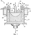
Фиг.1 изображает вертикальное поперечное сечение литейной установки, подходящей для использования в примерах вариантов осуществления настоящего изобретения.Figure 1 depicts a vertical cross section of a foundry installation suitable for use in examples of embodiments of the present invention.
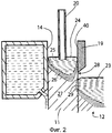
Фиг.2 схематически изображает зону взаимного контакта металлических сплавов в части установки фиг.1, где показаны области металла в твердом, жидком и полутвердом состоянии, которые, как предполагается, возникают во время литья.Figure 2 schematically depicts the zone of mutual contact of metal alloys in the installation of figure 1, which shows the areas of the metal in the solid, liquid and semi-solid state, which are expected to occur during casting.
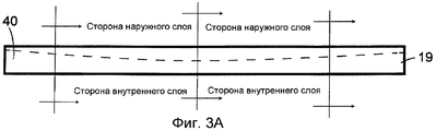
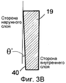
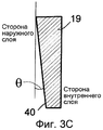
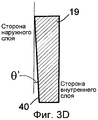
Фиг.3A-3D иллюстрируют одну форму разделительной перегородки, используемую в установке фиг.1, при этом разделительная перегородка показана в перспективной проекции и поясняется сечениями.FIGS. 3A-3D illustrate one form of a dividing wall used in the apparatus of FIG. 1, wherein the dividing wall is shown in perspective and is illustrated in cross-sections.
Фиг.4 изображает другой пример разделительной перегородки, форма которой соответствует варианту осуществления настоящего изобретения.Figure 4 depicts another example of a partition wall, the shape of which corresponds to an embodiment of the present invention.
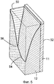
Фиг.5 представляет один конец слитка, отливаемого в установке фиг.1 (слиток изображен в виде вертикального сечения по его осевой линии); на фиг.5 показана глубина лунки расплавленного металла в местах, находящихся ближе к поверхности торца слитка; иFigure 5 represents one end of the ingot cast in the apparatus of Figure 1 (the ingot is depicted as a vertical section along its centerline); figure 5 shows the depth of the hole of molten metal in places closer to the surface of the end face of the ingot; and
Фиг.6 комбинированное вертикальное сечение литейной установки, подобное фиг.1, но построенное в соответствии с одним вариантом осуществления настоящего изобретения, на котором показано частичное сечение для области, примыкающей к одному концу слитка, и второе частичное сечение для области середины слитка.6 is a combined vertical section of a casting plant similar to FIG. 1, but constructed in accordance with one embodiment of the present invention, showing a partial section for a region adjacent to one end of the ingot, and a second partial section for the region of the middle of the ingot.
Осуществление изобретенияThe implementation of the invention
Настоящее изобретение может быть использовано совместно с литейной установкой, описанной в патентной публикации США 2005/0011630 от 20 января 2005 г. (Anderson и др.), содержание которой включено в настоящее изобретение посредством ссылки. Указанная литейная установка позволяет осуществлять литье металлов с последовательной кристаллизацией с целью формирования, по меньшей мере, одного наружного слоя (т.е. оболочечного слоя) на внутреннем слое (т.е. срединном слое или сердцевине слитка). В данном изобретении используются и получают развитие способы, раскрытые в патенте США 6260602 (Wagstaff), содержание которого включено в настоящее изобретение посредством ссылки.The present invention can be used in conjunction with the foundry described in US Patent Publication 2005/0011630 of January 20, 2005 (Anderson et al.), The contents of which are incorporated herein by reference. Said foundry allows casting of metals with sequential crystallization in order to form at least one outer layer (i.e., a shell layer) on the inner layer (i.e., the middle layer or core of the ingot). In the present invention, methods disclosed in US Pat. No. 6,260,602 (Wagstaff), the contents of which are incorporated herein by reference, are used and are being developed.
Следует пояснить, что термины «наружный» и «внутренний» используются в настоящем описании довольно свободно. Например, в двухслойной структуре, строго говоря, может и не существовать как таковых наружного слоя или внутреннего слоя, но обычно наружным слоем считается тот, который предназначен для контакта с атмосферой, климатическими факторами, или тот, который виден глазом в конечном изделии. Также часто «наружный» слой имеет меньшую толщину, чем «внутренний» - он обычно значительно тоньше, и, таким образом, предусматривается в качестве слоя покрытия или оболочки для подстилающего, «внутреннего» слоя или сердцевины слитка. В случае слитков, предназначенных для горячего и/или холодного прокатывания с целью получения листовых изделий, часто желательно наносить покрытие на обе главные (прокатываемые) поверхности слитка, и в этом случае указанные слои естественно различают, как «внутренний» слой и «наружные» слои. В некоторых случаях внутренний слой часто называют «сердцевиной» или «сердцевиной слитка», а наружные слои называют «оболочкой» или «плакированием».It should be clarified that the terms "external" and "internal" are used in the present description rather loosely. For example, in a two-layer structure, strictly speaking, the outer layer or inner layer may not exist as such, but usually the outer layer is one that is designed to come in contact with the atmosphere, climatic factors, or one that is visible to the eye in the final product. Also often, the “outer” layer has a smaller thickness than the “inner” one - it is usually much thinner, and thus is provided as a coating or sheath layer for the underlying, “inner” layer or core of the ingot. In the case of ingots intended for hot and / or cold rolling in order to obtain sheet products, it is often desirable to coat both main (rolled) surfaces of the ingot, in which case these layers are naturally distinguished as the “inner” layer and “outer” layers . In some cases, the inner layer is often referred to as the “core” or “core of the ingot”, and the outer layers are called the “shell” or “cladding”.
На фиг.1 показана соответствующая изобретению литейная установка 10, основанная на идеях, раскрытых в патентной публикации США 2005/0011630, которая используется для литья наружного слоя 11 на обе главные (прокатываемые) поверхности внутреннего слоя прямоугольной формы или на сердцевину 12 слитка. Следует отметить, что в данной версии установки в процессе литья покрывающие слои кристаллизуются первыми (по меньшей мере, частично), а затем происходит литье внутреннего слоя 12, соприкасающегося с покрывающими слоями. Приводимые примеры вариантов осуществления изобретения относятся главным образом к такому типу построения установки. Установка включает в себя литейный кристаллизатор 13, в общем, прямоугольной формы, у которого имеются стенки 14, которые формируют часть водяной рубашки 15, и с которых внешний поток 16 охлаждающей воды изливается на выходящий слиток 17. Слитки, отливаемые таким способом, в общем имеют прямоугольное поперечное сечение и размер до 1780×890 мм. Они часто используются для прокатывания на прокатных станах в плакированный листовой материал традиционными способами холодной и горячей прокатки. Следует отметить, что в некоторых вариантах осуществления изобретения стенки 14 кристаллизатора в их средней части могут быть слегка изогнуты в наружном направлении (на виде в плане), чтобы учесть тепловое сокращение (усадку) слитка при его охлаждении, и тем самым, придать охлажденному слитку более точную прямоугольную форму.Figure 1 shows the
Часть 18 стороны входа в кристаллизатор разделена двумя разделительными перегородками 19 (иногда называемые «охлаждающими» или «холодильными» перегородками) на три камеры подачи металла - по одной камере для каждого слоя структуры слитка. Разделительные перегородки 19, которые для обеспечения хорошей теплопроводности часто выполняют из меди, поддерживают в холодном состоянии за счет холодильного оборудования, охлаждаемого водой (не показано), которое связано с разделительными перегородками в точках, лежащих выше уровней расплавленных металлов. Как следствие, данные разделительные перегородки охлаждают и, в конечном счете, вызывают кристаллизацию расплавленного металла, который входит с ними в соприкосновение. Как показано стрелками А, каждая из трех камер снабжается расплавленным металлом до требуемого уровня через отдельные разливочные наконечники 20 подачи расплавленного металла, оснащенные регулируемой заслонкой (не показана) для поддержания постоянства уровня металла в соответствующих питающих камерах. Металл 24, выбираемый для наружных слоев 11, обычно отличается от металла 23 сердцевины 12, хотя в этом не всегда есть необходимость, и иногда требуется производить совместное литье отдельных слоев одного и того же металла. Нижний блок 21, выполненный с возможностью вертикального перемещения, вначале закрывает отверстие нижней стороны 22 кристаллизатора, а затем в процессе литья опускается (как показано стрелкой В), поддерживая при этом зародыш составного слитка 17, по мере того как последний выходит из кристаллизатора.
На фиг.2 в увеличенном виде показана зона установки фиг.1, прилегающая к левой разделительной перегородке 19, где металл 23 внутреннего слоя 12, и металл 24 левого плакирующего слоя 11 вступают во взаимный контакт в кристаллизаторе (в некоторых случаях это происходит ниже кристаллизатора). Металлические сплавы, переходя из жидкого состояния в твердое состояние, проходят через промежуточное полутвердое или «пористое» состояние, когда температура металла находится между температурой перехода в жидкое состояние (температурой ликвидуса) и температурой перехода в твердое состояние (температурой солидуса) для рассматриваемого металла. У металла 24, образующего плакирующий слой 11, имеется область 25 лунки расплавленного металла, область 26 полутвердого или «пористого» состояния, расположенная вокруг указанной лунки расплава, и область 27 полностью твердого состояния, в общем, расположенная ниже области пористого состояния, причем характер контура указанных областей во многом определяется охлаждающим действием стенки 14 кристаллизатора и разделительной перегородки 19. Теоретически поверхность 28 плакирующего слоя 11 непосредственно под охлажденной разделительной перегородкой 19 полностью затвердевает, но находится при температуре чуть ниже температуры солидуса рассматриваемого металла. Несколько ниже нижнего конца разделительной перегородки 19 данная поверхность соприкасается с расплавленным металлом 23 внутреннего слоя 12, и теплота расплавленного металла внутреннего слоя поднимает температуру твердой поверхности 28 плакирующего слоя в местах их первого контакта. Это приводит к тому, что в пределах неглубокой области 29 на поверхности 28 металл становится «пористым», когда его температура повышается до уровня между температурами солидуса и ликвидуса плакирующего металла. При этом область 29 плакирующего слоя остается окруженной твердым металлом 27.Figure 2 shows in an enlarged view the installation zone of Figure 1 adjacent to the
Установлено, что (по не до конца понятным причинам), когда металлы внутреннего и плакирующего слоев одинаковы или имеют близкие коэффициенты усадки (например, разнящиеся менее чем на 30%, а предпочтительном, менее чем на 10%), плакирующий слой может временно связываться с внутренней поверхностью 40 охлажденной разделительной перегородки вместо того, чтобы плавно стекать по данной поверхности по мере осуществления литейного процесса. Данный эффект возможно объясняется силами термического сокращения, возникающими при остывании металлов и наиболее заметен в середине кристаллизатора, т.е. в средней части кристаллизатора по его длине, между сторонами входа и выхода. Обнаружено, что при своем перемещении вертикально вниз плакирующие слои кратковременно приостанавливаются, а затем резко сползают, чтобы восполнить остановку движения. Во время прекращения движения плакирующего слоя может продолжаться отбор тепла охлажденной разделительной перегородкой 19, и металл на поверхности 28 может становиться переохлажденным. Когда такая переохлажденная поверхность опускается и вступает в контакт с расплавленным металлом 23 внутреннего слоя, то повторного нагрева, образующего пористую область 29 в плакирующем слое, может не произойти вовсе или он может оказаться более ограниченным, чем в ином случае. И, поэтому, требуемое сцепление слоев, которое вызывается таким повторным нагревом, может оказаться более слабым или вообще будет исключено. Это может привести к нежелательному разделению слоев во время последующей прокатки или иной обработки плакированного слитка.It was found that (for reasons not completely understood), when the metals of the inner and cladding layers are the same or have similar shrinkage coefficients (for example, differing by less than 30%, and preferably less than 10%), the cladding layer may temporarily bind to the
Теоретически указанная проблема сильнее проявляется в середине слитка, чем на его краях, потому что лунка расплавленного металла внутреннего слоя имеет наибольшую глубину в центре выходящего из кристаллизатора слитка (куда и подается расплавленный металл). Значительная глубина лунки приводит к тому, что в данной области внутреннего слоя развиваются увеличенные силы теплового сжатия, которые тянут плакирующий слой в направлении разделительной перегородки. По мере того как расплавленный металл кристаллизуется, развиваются силы термического сжатия, которые действуют параллельно твердеющей поверхности. Следовательно, когда лунка глубока, длина поверхности кристаллизации между плакирующим слоем и центром слитка оказывается большой, и развивающиеся силы оказываются более значительными, чем в тех местах, где лунка более мелкая.Theoretically, this problem is more pronounced in the middle of the ingot than at its edges, because the hole of the molten metal of the inner layer has the greatest depth in the center of the ingot emerging from the mold (where the molten metal is fed). The considerable depth of the hole leads to the fact that in this region of the inner layer, increased forces of thermal compression develop, which pull the clad layer in the direction of the dividing wall. As molten metal crystallizes, thermal compression forces develop that act parallel to the hardening surface. Therefore, when the hole is deep, the length of the crystallization surface between the cladding layer and the center of the ingot is large, and the developing forces are more significant than in those places where the hole is smaller.
В примерах осуществления настоящего изобретения данная проблема решается за счет введения скоса или углового наклона поверхности 40 разделительных перегородок 19, которая соприкасается с металлом плакирующего слоя (или слоев). Это означает, что поверхность 40 разделительной перегородки 19, которая соприкасается с металлом наружного или плакирующего слоя и ограничивает его, в направлении от верха к низу разделительной перегородки расположена под углом, с уклоном от металла наружного слоя (т.е. с уклоном в направлении внутреннего слоя). Угол уклона сделан сравнительно большим в средней части кристаллизатора, при этом он уменьшается по длине кристаллизатора в промежутках между средней частью и концами канала кристаллизатора. Скос снижает интенсивность контакта и величину сил, действующих между металлом плакирующего слоя и поверхностью разделительной перегородки. Угол скоса желательно выбирать так, чтобы оптимальным образом уменьшить вышеупомянутые силы (и, следовательно, уменьшить вероятность заедания металла при литье), но при этом все же поддерживать достаточный контакт для надлежащего задания направления движения металла и его охлаждения. Например, в литейной установке, показанной на фиг.1, разделительная перегородка 19 может быть скошена или отклонена от вертикали на угол, который в средней части кристаллизатора предпочтительно должен находиться в интервале от 1 до 10°, а оптимально от 3 до 7°, но должен быть уменьшен до менее чем 3°, а оптимально до менее, чем 2° или даже менее 1° на концах канала кристаллизатора или вблизи концов канала, где, как считается, силы теплового сжатия имеют меньшую величину. В каждом частном случае фактически выбираемые углы могут зависеть от соотношения коэффициентов усадки металлов внутреннего и наружного слоев.In embodiments of the present invention, this problem is solved by introducing a bevel or angular inclination of the
Увеличение уклона разделительных перегородок в направлении соответствующей средней части схематически показано на фиг.3A-3D, на которых угол скоса в середине представлен углом 9, а угол скоса на концах или вблизи концов (в продольном направлении) представлен углом θ'. Желательно, чтобы угол θ в середине перегородки, по меньшей мере, в два раза превосходил угол θ' на ее концах, но это может зависеть от конкретных используемых сплавов. Установлено, что полезен каждый лишний градус, увеличивающий угол скоса в направлении середины разделительной перегородки, однако к существенному улучшению приводит двукратная или большая разница углов, что является предпочтительным. Оптимальный угол для любого конкретного набора условий можно легко определить эмпирически, проводя испытания литейных операций с использованием различных углов и наблюдая за результатами. Конечно, следует понимать, что введение углового наклона поверхности разделительной перегородки необходимо только в зоне, где указанная поверхность соприкасается с металлом наружного слоя слитка, т.е. в направлении нижнего конца разделительной перегородки, однако для упрощения изготовления или упрощения операции может быть введен угловой наклон для всей поверхности.An increase in the slope of the partition walls in the direction of the corresponding middle part is shown schematically in FIGS. 3A-3D, in which the bevel angle in the middle is represented by an angle of 9 and the bevel angle at the ends or near the ends (in the longitudinal direction) is represented by the angle θ '. It is desirable that the angle θ in the middle of the partition is at least two times greater than the angle θ 'at its ends, but this may depend on the particular alloys used. It has been established that every extra degree that increases the angle of inclination in the direction of the middle of the dividing wall is useful, however, a twofold or a large difference in angles leads to a significant improvement, which is preferred. The optimal angle for any given set of conditions can be easily determined empirically by conducting tests of foundry operations using various angles and observing the results. Of course, it should be understood that the introduction of the angular inclination of the surface of the partition wall is necessary only in the area where the specified surface is in contact with the metal of the outer layer of the ingot, i.e. toward the lower end of the partition wall, however, to simplify manufacturing or simplify the operation, an angular inclination for the entire surface can be introduced.
Увеличение угла наклона поверхности 40 разделительной перегородки 19 в направлении ее средней части может происходить монотонно и линейно по длине разделительной перегородки от середины к концам. Однако не всегда есть необходимость увеличивать угол скоса таким образом. В другом примере осуществления изобретения угол наклона на концах разделительной перегородки на определенном расстоянии остается постоянным, а затем возрастает до угла, подходящего для средней части. Места, где угол наклона увеличивается (или начинает увеличиваться) на каждой стороне перегородки внутрь от ее концов, могут быть назначены приблизительно в единицах четвертей длины слитка. То есть средняя область с постоянным (максимальным) наклоном занимает центральную зону (вторую и третью четверти) до точек, соответствующих, приблизительно, одной четверти и трем четвертям длины разделительной перегородки, а затем угол наклона уменьшается (и затем может оставаться постоянным) в пределах более удаленных первой и четвертой четверти. Разделительная перегородка со скосом, выполненным таким образом, показана на фиг.4. Возможная причина для такой геометрии объясняется согласно фиг.5.The increase in the angle of inclination of the
На фиг.5 представлена область конца слитка в процессе литья в виде вертикального сечения вблизи осевой линии (так называемой «плоскости теплового излучения»). На данном изображении литейная установка опущена, и показан только отливаемый металл. Для наглядности расплавленный металл показан прозрачным, в то время как твердый металл показан перекрестной штриховкой. Поверхности (показанные прерывистыми линиями) представляют собой места перехода от расплавленного металла к твердому (области полутвердого состояния для простоты опущены). Охлаждение происходит от поверхности 50 на торце слитка, а также от боковой поверхности 52, так что лунка расплавленного металла постепенно становится более мелкой, приближаясь к торцовой поверхности 50. Обычно имеется некоторая точка 54 (часто на расстоянии приблизительно четверти или трех четвертей по длине слитка), где дно лунки круто уходит под углом вверх, а далее еще одна точка 56, где подъем дна лунки становится еще более крутым, а также обычно имеется бифуркация, где стенки лунки, параллельные концевой и боковой поверхностям, встречаются друг с другом. По другую сторону точки 54 в направлении оси слитка, где происходит подача расплавленного металла, дно лунки остается в общем горизонтальным или меняет наклон лишь под небольшим углом, пока с противоположной стороны слитка не встретится точка, эквивалентная точке 54. В такой ситуации силы сжатия, действующие на слиток и плакирующий слой, уменьшаются с приближением к торцу 50, и этот процесс начинается в точках, где лунка становится более глубокой. Это происходит из-за того, что силы сжатия уменьшаются с уменьшением глубины лунки. Угол скоса соответствующей разделительной перегородки может оставаться постоянным (или максимальным) в средней области слитка там, где глубина лунки максимальна, а дно лунки, в общем, горизонтально, и может измениться (стать меньше) около точки 54, или, возможно, около точки 56. Углы скоса могут меняться резко, на небольшом расстоянии, или монотонно к торцовой поверхности слитка. Изменение угла скоса может точно соответствовать изменению глубины лунки по длине слитка (т.е. угол скоса может уменьшаться от середины к концу слитка пропорционально глубине лунки), но может оказаться затруднительным добиться этого на практике, и в общем случае это может и не требоваться. Обычно достаточно приближенного соответствия, поскольку определение точного контура дна лунки в процессе получения слитка может быть трудной задачей.Figure 5 presents the region of the end of the ingot during casting in the form of a vertical section near the center line (the so-called "plane of thermal radiation"). In this image, the foundry is omitted and only the cast metal is shown. For clarity, molten metal is shown transparent, while solid metal is shown by cross-hatching. Surfaces (indicated by dashed lines) represent the transition from molten to solid metal (the semi-solid state regions are omitted for simplicity). Cooling takes place from the
Помимо введения скоса с увеличивающимся углом в направлении средней части, разделительная перегородка 19 может также быть выполнена с дугообразным изгибом наружу, который должен принимать на себя грани слитка по его длинной стороне при его термическом сокращении в процессе остывания и затвердевания (такой изгиб аналогичен изгибу, показанному на фиг.7 патентной заявки США 2005/0011630). Это компенсирует возможную «кривизну» указанных граней и позволяет получать боковые поверхности, более близкие к идеальной плоской форме, что является желательным для прокатывания слитка в листовые изделия.In addition to introducing a bevel with an increasing angle in the direction of the middle part, the dividing
Хотя это и не показано на чертежах, но внутренние литейные поверхности длинных стенок 14 кристаллизатора могут быть либо вертикальными, либо могут сами быть выполнены со скосом, т.е. с уклоном наружу в направлении нижней части кристаллизатора (в этом случае угол скоса обычно доходил бы, приблизительно, до 1°). Однако, когда для стенки 14 кристаллизатора применяется скос такого типа, угол скоса в общем сохраняется один и тот же для всей длины стенки кристаллизатора.Although not shown in the drawings, the inner casting surfaces of the
Фиг.6 представляет собой вид, который аналогичен виду фиг.1, и который демонстрирует литейную установку, соответствующую одному из вариантов осуществления настоящего изобретения. Изображение разделено по вертикальной оси литейной установки на две части. Правая сторона изображает вертикальное поперечное сечение установки для точки на середине длины слитка, а левая сторона изображает сечение литейного кристаллизатора для места, расположенного ближе к концу слитка. Эти две половины чертежа иллюстрируют различные углы (θ и θ') разделительных перегородок 19 в указанных различных местах, а также разную высоту точки кристаллизации металла внутреннего слоя в этих точках на оси слитка. Видно, что угол скоса θ' у конца слитка гораздо меньше, чем аналогичный угол в середине слитка (угол θ).FIG. 6 is a view that is similar to that of FIG. 1, and which shows a casting machine according to one embodiment of the present invention. The image is divided into two parts along the vertical axis of the foundry. The right side depicts the vertical cross section of the installation for a point in the middle of the length of the ingot, and the left side depicts a cross section of the mold for a place closer to the end of the ingot. These two halves of the drawing illustrate the different angles (θ and θ ') of the
Применение настоящего изобретения может быть особенно полезным для совместного литья следующих сочетаний сплавов. Следует понимать, что указанные сочетания приведены только для примера, и, что изобретение также может быть полезным для совместного литья и других сочетаний сплавов. В следующих сочетаниях сплавов для указания их составов используются числовые обозначения (АА), при этом сплав плакирующего слоя указан первым:The use of the present invention may be particularly useful for co-casting the following alloy combinations. It should be understood that these combinations are given only as an example, and that the invention may also be useful for co-casting and other combinations of alloys. In the following combinations of alloys, numerical designations (AA) are used to indicate their compositions, while the alloy of the clad layer is indicated first:
3003/31043003/3104
6063/6111 и6063/6111 and
5005/5052.5005/5052.
Вышеприведенное описание касается формирования прямоугольного слитка, но подобное варьирование угла скоса может быть использовано для плакированных слитков любой формы в случаях, когда приходится сталкиваться со снижением сцепления слоев в середине слитка. В общем изобретение дает эффект, когда первым производится литье плакирующего(-щих) слоя(-ев).The above description relates to the formation of a rectangular ingot, but a similar variation of the bevel angle can be used for clad ingots of any shape in cases where it is necessary to experience a decrease in the adhesion of the layers in the middle of the ingot. In general, the invention provides an effect when the cladding layer (s) are cast first.
Claims (14)
сквозную формообразующую полость кристаллизатора, которая имеет, по существу, прямоугольное сечение и содержит входную часть, выпускное отверстие и подвижный нижний блок, выполненный с возможностью посадки в выпускное отверстие и перемещения вдоль оси кристаллизатора в процессе литья;
по меньшей мере, одну охлаждаемую разделительную перегородку во входной части кристаллизатора для разделения входной части, по меньшей мере, на две камеры подачи металла; и
подающее устройство для подвода металла для внутреннего слоя к одной из указанных, по меньшей мере, двух камер подачи металла и, по меньшей мере, одно дополнительное подающее устройство для подвода металла, по меньшей мере, для одного наружного слоя, по меньшей мере, к одной другой из указанных камер подачи металла,
при этом, по меньшей мере, одна разделительная перегородка имеет поверхность контакта с металлом, которая при работе кристаллизатора соприкасается с металлом, по меньшей мере, одного наружного слоя, причем указанная поверхность наклонена под углом от металла наружного слоя в направлении течения металла через кристаллизатор, при этом в средней части, по меньшей мере, одной разделительной перегородки указанный угол наклона больше, чем в местах, примыкающих к концам, по меньшей мере, одной разделительной перегородки.1. Installation for casting a composite metal ingot containing
a through mold cavity of the mold, which has a substantially rectangular cross section and includes an inlet, an outlet and a movable lower unit configured to fit into the outlet and move along the axis of the mold during casting;
at least one cooled dividing wall in the inlet part of the mold for dividing the inlet part into at least two metal feed chambers; and
a feed device for supplying metal for the inner layer to one of the at least two metal feed chambers and at least one additional supply device for supplying metal for at least one outer layer to at least one another of these metal feed chambers,
wherein at least one dividing wall has a metal contact surface which, when the mold is in operation, is in contact with the metal of at least one outer layer, said surface inclined at an angle from the metal of the outer layer in the direction of metal flow through the mold, this in the middle part of at least one dividing wall, the specified angle of inclination is greater than in places adjacent to the ends of at least one dividing wall.
подготавливают установку для литья составного металлического слитка, включающую в себя сквозную формообразующую полость кристаллизатора, которая имеет, по существу, прямоугольное сечение и содержит входную часть, выпускное отверстие и подвижный нижний блок, выполненный с возможностью посадки в выпускное отверстие и перемещения вдоль оси кристаллизатора в процессе литья; по меньшей мере, одну охлаждаемую разделительную перегородку во входной части кристаллизатора для разделения входной части, по меньшей мере, на две камеры подачи металла; и подающее устройство для подвода металла для внутреннего слоя к одной из указанных, по меньшей мере, двух камер подачи металла и, по меньшей мере, одно дополнительное подающее устройство для подвода металла, по меньшей мере, для одного наружного слоя, по меньшей мере, к одной другой из указанных камер подачи металла, при этом, по меньшей мере, одна разделительная перегородка имеет поверхность контакта с металлом, которая при работе кристаллизатора соприкасается с металлом, по меньшей мере, одного наружного слоя, причем указанная поверхность наклонена под углом от металла наружного слоя в направлении течения металла через кристаллизатор, при этом в средней части, по меньшей мере, одной разделительной перегородки указанный угол наклона больше, чем в местах, примыкающих к концам, по меньшей мере, одной разделительной перегородки;
подают металл для внутреннего слоя в одну из указанных, по меньшей мере, двух камер подачи металла;
подают металл, по меньшей мере, для одного наружного слоя, по меньшей мере, в одну другую из указанных камер подачи металла, причем металл для внутреннего слоя и металл, по меньшей мере, для одного наружного слоя выбирают так, чтобы указанные металлы имели равные или близкие коэффициенты усадки; и
перемещают нижний блок вдоль оси кристаллизатора для обеспечения возможности выхода слитка из выпускного отверстия установки.10. A method for casting a composite ingot, comprising the steps of:
prepare the installation for casting a composite metal ingot, including a through mold cavity of the mold, which has a substantially rectangular cross section and contains an inlet, an outlet and a movable lower unit configured to fit into the outlet and move along the axis of the mold in the process casting; at least one cooled dividing wall in the inlet part of the mold for dividing the inlet part into at least two metal feed chambers; and a feeding device for supplying metal for the inner layer to one of said at least two metal supply chambers and at least one additional feeding device for supplying metal for at least one outer layer to at least one of the other metal supply chambers, wherein at least one dividing wall has a metal contact surface which, when the mold is in operation, is in contact with the metal of at least one outer layer, said surface l is inclined at an angle from the metal of the outer layer in the direction of the metal flow through the mold, while in the middle part of at least one dividing wall, the specified angle of inclination is greater than in places adjacent to the ends of at least one dividing wall;
supplying metal for the inner layer to one of said at least two metal feed chambers;
supplying metal for at least one outer layer to at least one other of said metal supply chambers, the metal for the inner layer and the metal for at least one outer layer being selected so that these metals have equal or close shrinkage coefficients; and
move the bottom block along the axis of the mold to allow the ingot to exit the outlet of the installation.
Applications Claiming Priority (2)
| Application Number | Priority Date | Filing Date | Title |
|---|---|---|---|
| US96660307P | 2007-08-29 | 2007-08-29 | |
| US60/966,603 | 2007-08-29 |
Publications (2)
| Publication Number | Publication Date |
|---|---|
| RU2010108668A RU2010108668A (en) | 2011-10-10 |
| RU2460607C2 true RU2460607C2 (en) | 2012-09-10 |
Family
ID=40386597
Family Applications (1)
| Application Number | Title | Priority Date | Filing Date |
|---|---|---|---|
| RU2010108668/02A RU2460607C2 (en) | 2007-08-29 | 2008-06-23 | Device and method for subsequent casting of metals having equal or similar shrinkage factors |
Country Status (13)
| Country | Link |
|---|---|
| US (1) | US7882887B2 (en) |
| EP (1) | EP2188079B1 (en) |
| JP (1) | JP5432146B2 (en) |
| KR (1) | KR101403764B1 (en) |
| CN (1) | CN101795791B (en) |
| AU (1) | AU2008291636B2 (en) |
| BR (1) | BRPI0815781B1 (en) |
| CA (1) | CA2695840C (en) |
| ES (1) | ES2488491T3 (en) |
| PL (1) | PL2188079T3 (en) |
| RU (1) | RU2460607C2 (en) |
| WO (1) | WO2009026671A1 (en) |
| ZA (1) | ZA201001152B (en) |
Families Citing this family (18)
| Publication number | Priority date | Publication date | Assignee | Title |
|---|---|---|---|---|
| EP2279813B1 (en) * | 2003-06-24 | 2017-06-07 | Novelis, Inc. | Method for casting composite ingot |
| US20060137851A1 (en) * | 2004-12-27 | 2006-06-29 | Gyan Jha | Shaped direct chill aluminum ingot |
| US8381385B2 (en) * | 2004-12-27 | 2013-02-26 | Tri-Arrows Aluminum Inc. | Shaped direct chill aluminum ingot |
| BRPI0913981B1 (en) * | 2008-07-31 | 2018-03-06 | Novelis Inc. | APPLIANCE FOR LINGOTING A COMPOSITE METAL LANGUAGE AND METHOD FOR LINGING A COMPOSITE LANGUAGE MADE OF METALS WITH SIMILAR SOLIDIFICATION TEMPERATURE RANGE |
| CA2685750A1 (en) * | 2008-11-14 | 2010-05-14 | Novelis Inc. | Composite aluminum tread plate sheet |
| WO2010144997A1 (en) * | 2009-06-16 | 2010-12-23 | Novelis Inc. | Sheet product having an outer surface optimized for anodization |
| CN102740996B (en) * | 2010-02-11 | 2014-11-12 | 诺维尔里斯公司 | Casting composite ingot with metal temperature compensation |
| JP2012086250A (en) * | 2010-10-20 | 2012-05-10 | Toyota Motor Corp | Aluminum alloy clad plate and method of manufacturing the same |
| CN103502747B (en) | 2010-12-22 | 2016-10-26 | 诺维尔里斯公司 | Solar collector unit and comprise its solar energy equipment |
| CN102069160B (en) * | 2011-01-31 | 2012-09-12 | 中冶京诚工程技术有限公司 | Ultra-large rectangular ingot blank sloping casting combined manufacturing device and method |
| RU2492021C1 (en) * | 2012-05-14 | 2013-09-10 | Открытое акционерное общество "Магнитогорский металлургический комбинат" | Method of steel continuous casting |
| CN103100700B (en) * | 2013-01-21 | 2015-07-29 | 东北大学 | For covering and casting device and the covering and casting method of aluminum alloy compounded ingot |
| CA2896729C (en) | 2013-03-12 | 2017-10-17 | Novelis Inc. | Intermittent molten metal delivery |
| KR20170096048A (en) | 2014-12-22 | 2017-08-23 | 노벨리스 인크. | Clad sheet for heat exchanger |
| CN106735000B (en) * | 2016-11-14 | 2018-10-23 | 东北大学 | A kind of semi-continuous casting device and method of three layers of cladding ingot casting |
| PL3548208T3 (en) | 2017-11-15 | 2023-08-21 | Novelis Inc. | Metal level overshoot or undershoot mitigation at transition of flow rate demand |
| CN108526425B (en) * | 2018-03-30 | 2020-09-01 | 鞍钢股份有限公司 | Composite metal continuous casting device and continuous casting method |
| KR102171086B1 (en) * | 2018-09-28 | 2020-10-28 | 주식회사 포스코 | Casting simulator and for simulation method for casting |
Citations (4)
| Publication number | Priority date | Publication date | Assignee | Title |
|---|---|---|---|---|
| SU799906A1 (en) * | 1978-11-10 | 1981-01-30 | Харьковский Институт Механизациии Электрификации Сельскогохозяйства | Open-ended mould for continuous casting of plated ingots |
| SU1447544A1 (en) * | 1987-05-25 | 1988-12-30 | Научно-производственное объединение "Тулачермет" | Method of continuous casting of bimetallic ingots |
| US6705384B2 (en) * | 2001-10-23 | 2004-03-16 | Alcoa Inc. | Simultaneous multi-alloy casting |
| US20050011630A1 (en) * | 2003-06-24 | 2005-01-20 | Anderson Mark Douglas | Method for casting composite ingot |
Family Cites Families (9)
| Publication number | Priority date | Publication date | Assignee | Title |
|---|---|---|---|---|
| US4567936A (en) * | 1984-08-20 | 1986-02-04 | Kaiser Aluminum & Chemical Corporation | Composite ingot casting |
| US4724896A (en) * | 1987-02-09 | 1988-02-16 | Aluminum Company Of America | Apparatus and method for improving the surface characteristics of continuously cast metal ingot |
| US6158498A (en) * | 1997-10-21 | 2000-12-12 | Wagstaff, Inc. | Casting of molten metal in an open ended mold cavity |
| JP2006130553A (en) * | 2004-11-09 | 2006-05-25 | Hitachi Cable Ltd | Mold for continuous casting |
| US7617864B2 (en) | 2006-02-28 | 2009-11-17 | Novelis Inc. | Cladding ingot to prevent hot-tearing |
| US7748434B2 (en) * | 2006-03-01 | 2010-07-06 | Novelis Inc. | Sequential casting of metals having high co-efficients of contraction |
| US7762310B2 (en) | 2006-04-13 | 2010-07-27 | Novelis Inc. | Cladding superplastic alloys |
| JP2010519055A (en) | 2007-02-28 | 2010-06-03 | ノベリス・インコーポレイテッド | Simultaneous casting of metals by direct chill casting |
| CA2724754C (en) * | 2008-05-22 | 2013-02-05 | Novelis Inc. | Oxide restraint during co-casting of metals |
-
2008
- 2008-06-23 KR KR1020107005709A patent/KR101403764B1/en active IP Right Grant
- 2008-06-23 EP EP08772842.4A patent/EP2188079B1/en active Active
- 2008-06-23 BR BRPI0815781A patent/BRPI0815781B1/en active IP Right Grant
- 2008-06-23 AU AU2008291636A patent/AU2008291636B2/en not_active Ceased
- 2008-06-23 CN CN200880106165XA patent/CN101795791B/en active Active
- 2008-06-23 JP JP2010522141A patent/JP5432146B2/en active Active
- 2008-06-23 ES ES08772842.4T patent/ES2488491T3/en active Active
- 2008-06-23 RU RU2010108668/02A patent/RU2460607C2/en active
- 2008-06-23 PL PL08772842T patent/PL2188079T3/en unknown
- 2008-06-23 WO PCT/CA2008/001182 patent/WO2009026671A1/en active Application Filing
- 2008-06-23 CA CA2695840A patent/CA2695840C/en active Active
- 2008-07-29 US US12/220,954 patent/US7882887B2/en active Active
-
2010
- 2010-02-17 ZA ZA2010/01152A patent/ZA201001152B/en unknown
Patent Citations (4)
| Publication number | Priority date | Publication date | Assignee | Title |
|---|---|---|---|---|
| SU799906A1 (en) * | 1978-11-10 | 1981-01-30 | Харьковский Институт Механизациии Электрификации Сельскогохозяйства | Open-ended mould for continuous casting of plated ingots |
| SU1447544A1 (en) * | 1987-05-25 | 1988-12-30 | Научно-производственное объединение "Тулачермет" | Method of continuous casting of bimetallic ingots |
| US6705384B2 (en) * | 2001-10-23 | 2004-03-16 | Alcoa Inc. | Simultaneous multi-alloy casting |
| US20050011630A1 (en) * | 2003-06-24 | 2005-01-20 | Anderson Mark Douglas | Method for casting composite ingot |
Also Published As
| Publication number | Publication date |
|---|---|
| WO2009026671A1 (en) | 2009-03-05 |
| AU2008291636A1 (en) | 2009-03-05 |
| US7882887B2 (en) | 2011-02-08 |
| BRPI0815781B1 (en) | 2017-01-24 |
| RU2010108668A (en) | 2011-10-10 |
| KR101403764B1 (en) | 2014-06-03 |
| ZA201001152B (en) | 2011-04-28 |
| CA2695840A1 (en) | 2009-03-05 |
| EP2188079A4 (en) | 2013-04-24 |
| CA2695840C (en) | 2011-09-27 |
| PL2188079T3 (en) | 2015-01-30 |
| EP2188079B1 (en) | 2014-07-23 |
| CN101795791B (en) | 2012-07-11 |
| AU2008291636B2 (en) | 2011-09-15 |
| ES2488491T3 (en) | 2014-08-27 |
| KR20100057064A (en) | 2010-05-28 |
| CN101795791A (en) | 2010-08-04 |
| US20090056904A1 (en) | 2009-03-05 |
| BRPI0815781A2 (en) | 2015-03-03 |
| EP2188079A1 (en) | 2010-05-26 |
| JP5432146B2 (en) | 2014-03-05 |
| JP2010536579A (en) | 2010-12-02 |
Similar Documents
| Publication | Publication Date | Title |
|---|---|---|
| RU2460607C2 (en) | Device and method for subsequent casting of metals having equal or similar shrinkage factors | |
| RU2416485C2 (en) | Consecutive casting of metal with high compresion ratio | |
| US8415025B2 (en) | Composite metal as cast ingot | |
| RU2497628C2 (en) | Method and device for successive casting of metals that feature neighbor crystallisation temperature ranges | |
| RU2323799C2 (en) | Method of simultaneouse smelting of several alloys | |
| US7789124B2 (en) | Cladding ingot to prevent hot-tearing | |
| US8312916B2 (en) | Method for casting a composite ingot |