RU2456126C2 - Cutting plate with ceramic coating - Google Patents
Cutting plate with ceramic coating Download PDFInfo
- Publication number
- RU2456126C2 RU2456126C2 RU2009136033/02A RU2009136033A RU2456126C2 RU 2456126 C2 RU2456126 C2 RU 2456126C2 RU 2009136033/02 A RU2009136033/02 A RU 2009136033/02A RU 2009136033 A RU2009136033 A RU 2009136033A RU 2456126 C2 RU2456126 C2 RU 2456126C2
- Authority
- RU
- Russia
- Prior art keywords
- layer
- cutting insert
- coating
- tin
- layers
- Prior art date
Links
Images
Classifications
-
- B—PERFORMING OPERATIONS; TRANSPORTING
- B23—MACHINE TOOLS; METAL-WORKING NOT OTHERWISE PROVIDED FOR
- B23B—TURNING; BORING
- B23B27/00—Tools for turning or boring machines; Tools of a similar kind in general; Accessories therefor
- B23B27/14—Cutting tools of which the bits or tips or cutting inserts are of special material
-
- C—CHEMISTRY; METALLURGY
- C23—COATING METALLIC MATERIAL; COATING MATERIAL WITH METALLIC MATERIAL; CHEMICAL SURFACE TREATMENT; DIFFUSION TREATMENT OF METALLIC MATERIAL; COATING BY VACUUM EVAPORATION, BY SPUTTERING, BY ION IMPLANTATION OR BY CHEMICAL VAPOUR DEPOSITION, IN GENERAL; INHIBITING CORROSION OF METALLIC MATERIAL OR INCRUSTATION IN GENERAL
- C23C—COATING METALLIC MATERIAL; COATING MATERIAL WITH METALLIC MATERIAL; SURFACE TREATMENT OF METALLIC MATERIAL BY DIFFUSION INTO THE SURFACE, BY CHEMICAL CONVERSION OR SUBSTITUTION; COATING BY VACUUM EVAPORATION, BY SPUTTERING, BY ION IMPLANTATION OR BY CHEMICAL VAPOUR DEPOSITION, IN GENERAL
- C23C30/00—Coating with metallic material characterised only by the composition of the metallic material, i.e. not characterised by the coating process
- C23C30/005—Coating with metallic material characterised only by the composition of the metallic material, i.e. not characterised by the coating process on hard metal substrates
-
- C—CHEMISTRY; METALLURGY
- C23—COATING METALLIC MATERIAL; COATING MATERIAL WITH METALLIC MATERIAL; CHEMICAL SURFACE TREATMENT; DIFFUSION TREATMENT OF METALLIC MATERIAL; COATING BY VACUUM EVAPORATION, BY SPUTTERING, BY ION IMPLANTATION OR BY CHEMICAL VAPOUR DEPOSITION, IN GENERAL; INHIBITING CORROSION OF METALLIC MATERIAL OR INCRUSTATION IN GENERAL
- C23C—COATING METALLIC MATERIAL; COATING MATERIAL WITH METALLIC MATERIAL; SURFACE TREATMENT OF METALLIC MATERIAL BY DIFFUSION INTO THE SURFACE, BY CHEMICAL CONVERSION OR SUBSTITUTION; COATING BY VACUUM EVAPORATION, BY SPUTTERING, BY ION IMPLANTATION OR BY CHEMICAL VAPOUR DEPOSITION, IN GENERAL
- C23C16/00—Chemical coating by decomposition of gaseous compounds, without leaving reaction products of surface material in the coating, i.e. chemical vapour deposition [CVD] processes
- C23C16/02—Pretreatment of the material to be coated
- C23C16/0272—Deposition of sub-layers, e.g. to promote the adhesion of the main coating
-
- C—CHEMISTRY; METALLURGY
- C23—COATING METALLIC MATERIAL; COATING MATERIAL WITH METALLIC MATERIAL; CHEMICAL SURFACE TREATMENT; DIFFUSION TREATMENT OF METALLIC MATERIAL; COATING BY VACUUM EVAPORATION, BY SPUTTERING, BY ION IMPLANTATION OR BY CHEMICAL VAPOUR DEPOSITION, IN GENERAL; INHIBITING CORROSION OF METALLIC MATERIAL OR INCRUSTATION IN GENERAL
- C23C—COATING METALLIC MATERIAL; COATING MATERIAL WITH METALLIC MATERIAL; SURFACE TREATMENT OF METALLIC MATERIAL BY DIFFUSION INTO THE SURFACE, BY CHEMICAL CONVERSION OR SUBSTITUTION; COATING BY VACUUM EVAPORATION, BY SPUTTERING, BY ION IMPLANTATION OR BY CHEMICAL VAPOUR DEPOSITION, IN GENERAL
- C23C16/00—Chemical coating by decomposition of gaseous compounds, without leaving reaction products of surface material in the coating, i.e. chemical vapour deposition [CVD] processes
- C23C16/22—Chemical coating by decomposition of gaseous compounds, without leaving reaction products of surface material in the coating, i.e. chemical vapour deposition [CVD] processes characterised by the deposition of inorganic material, other than metallic material
- C23C16/30—Deposition of compounds, mixtures or solid solutions, e.g. borides, carbides, nitrides
- C23C16/32—Carbides
-
- C—CHEMISTRY; METALLURGY
- C23—COATING METALLIC MATERIAL; COATING MATERIAL WITH METALLIC MATERIAL; CHEMICAL SURFACE TREATMENT; DIFFUSION TREATMENT OF METALLIC MATERIAL; COATING BY VACUUM EVAPORATION, BY SPUTTERING, BY ION IMPLANTATION OR BY CHEMICAL VAPOUR DEPOSITION, IN GENERAL; INHIBITING CORROSION OF METALLIC MATERIAL OR INCRUSTATION IN GENERAL
- C23C—COATING METALLIC MATERIAL; COATING MATERIAL WITH METALLIC MATERIAL; SURFACE TREATMENT OF METALLIC MATERIAL BY DIFFUSION INTO THE SURFACE, BY CHEMICAL CONVERSION OR SUBSTITUTION; COATING BY VACUUM EVAPORATION, BY SPUTTERING, BY ION IMPLANTATION OR BY CHEMICAL VAPOUR DEPOSITION, IN GENERAL
- C23C16/00—Chemical coating by decomposition of gaseous compounds, without leaving reaction products of surface material in the coating, i.e. chemical vapour deposition [CVD] processes
- C23C16/22—Chemical coating by decomposition of gaseous compounds, without leaving reaction products of surface material in the coating, i.e. chemical vapour deposition [CVD] processes characterised by the deposition of inorganic material, other than metallic material
- C23C16/30—Deposition of compounds, mixtures or solid solutions, e.g. borides, carbides, nitrides
- C23C16/34—Nitrides
-
- C—CHEMISTRY; METALLURGY
- C23—COATING METALLIC MATERIAL; COATING MATERIAL WITH METALLIC MATERIAL; CHEMICAL SURFACE TREATMENT; DIFFUSION TREATMENT OF METALLIC MATERIAL; COATING BY VACUUM EVAPORATION, BY SPUTTERING, BY ION IMPLANTATION OR BY CHEMICAL VAPOUR DEPOSITION, IN GENERAL; INHIBITING CORROSION OF METALLIC MATERIAL OR INCRUSTATION IN GENERAL
- C23C—COATING METALLIC MATERIAL; COATING MATERIAL WITH METALLIC MATERIAL; SURFACE TREATMENT OF METALLIC MATERIAL BY DIFFUSION INTO THE SURFACE, BY CHEMICAL CONVERSION OR SUBSTITUTION; COATING BY VACUUM EVAPORATION, BY SPUTTERING, BY ION IMPLANTATION OR BY CHEMICAL VAPOUR DEPOSITION, IN GENERAL
- C23C16/00—Chemical coating by decomposition of gaseous compounds, without leaving reaction products of surface material in the coating, i.e. chemical vapour deposition [CVD] processes
- C23C16/22—Chemical coating by decomposition of gaseous compounds, without leaving reaction products of surface material in the coating, i.e. chemical vapour deposition [CVD] processes characterised by the deposition of inorganic material, other than metallic material
- C23C16/30—Deposition of compounds, mixtures or solid solutions, e.g. borides, carbides, nitrides
- C23C16/40—Oxides
- C23C16/403—Oxides of aluminium, magnesium or beryllium
-
- Y—GENERAL TAGGING OF NEW TECHNOLOGICAL DEVELOPMENTS; GENERAL TAGGING OF CROSS-SECTIONAL TECHNOLOGIES SPANNING OVER SEVERAL SECTIONS OF THE IPC; TECHNICAL SUBJECTS COVERED BY FORMER USPC CROSS-REFERENCE ART COLLECTIONS [XRACs] AND DIGESTS
- Y10—TECHNICAL SUBJECTS COVERED BY FORMER USPC
- Y10T—TECHNICAL SUBJECTS COVERED BY FORMER US CLASSIFICATION
- Y10T407/00—Cutters, for shaping
- Y10T407/27—Cutters, for shaping comprising tool of specific chemical composition
-
- Y—GENERAL TAGGING OF NEW TECHNOLOGICAL DEVELOPMENTS; GENERAL TAGGING OF CROSS-SECTIONAL TECHNOLOGIES SPANNING OVER SEVERAL SECTIONS OF THE IPC; TECHNICAL SUBJECTS COVERED BY FORMER USPC CROSS-REFERENCE ART COLLECTIONS [XRACs] AND DIGESTS
- Y10—TECHNICAL SUBJECTS COVERED BY FORMER USPC
- Y10T—TECHNICAL SUBJECTS COVERED BY FORMER US CLASSIFICATION
- Y10T428/00—Stock material or miscellaneous articles
- Y10T428/24—Structurally defined web or sheet [e.g., overall dimension, etc.]
- Y10T428/24942—Structurally defined web or sheet [e.g., overall dimension, etc.] including components having same physical characteristic in differing degree
- Y10T428/2495—Thickness [relative or absolute]
- Y10T428/24967—Absolute thicknesses specified
- Y10T428/24975—No layer or component greater than 5 mils thick
-
- Y—GENERAL TAGGING OF NEW TECHNOLOGICAL DEVELOPMENTS; GENERAL TAGGING OF CROSS-SECTIONAL TECHNOLOGIES SPANNING OVER SEVERAL SECTIONS OF THE IPC; TECHNICAL SUBJECTS COVERED BY FORMER USPC CROSS-REFERENCE ART COLLECTIONS [XRACs] AND DIGESTS
- Y10—TECHNICAL SUBJECTS COVERED BY FORMER USPC
- Y10T—TECHNICAL SUBJECTS COVERED BY FORMER US CLASSIFICATION
- Y10T428/00—Stock material or miscellaneous articles
- Y10T428/26—Web or sheet containing structurally defined element or component, the element or component having a specified physical dimension
- Y10T428/263—Coating layer not in excess of 5 mils thick or equivalent
- Y10T428/264—Up to 3 mils
- Y10T428/265—1 mil or less
Abstract
Description
ОБЛАСТЬ ТЕХНИКИFIELD OF TECHNOLOGY
Настоящее изобретение относится к улучшенным системам покрытия, и в частности, но не исключительно, к новым толстым покрытиям и способам их выполнения для использования на соответствующих основах для получения режущих инструментов, пластин и сменных режущих головок, имеющих улучшенные свойства, такие как, например, стойкость.The present invention relates to improved coating systems, and in particular, but not exclusively, to new thick coatings and methods for their implementation for use on appropriate bases for producing cutting tools, inserts and interchangeable cutting heads having improved properties, such as, for example, resistance .
УРОВЕНЬ ТЕХНИКИBACKGROUND
При обработке резанием заготовок посредством точения, фрезерования, сверления и подобных операций используются режущие инструменты. Чтобы гарантировать эффективное удаление стружки с заготовки и достаточную стойкость инструмента, режущая пластина режущего инструмента должна быть твердой и вязкой.When cutting workpieces by turning, milling, drilling and similar operations, cutting tools are used. To ensure effective removal of chips from the workpiece and sufficient tool life, the cutting insert of the cutting tool must be hard and viscous.
Твердость, однако, может быть взаимосвязана с хрупкостью. Весьма популярным выбором для пластин являются обладающие как твердостью, так и вязкостью композиционные материалы, содержащие твердые керамические частицы в металлической матрице. Разработан ряд таких металлокерамических композитов или керметов. Так называемые твердые металлы или твердые сплавы, в частности WC-Co, состоящие из зерен карбида вольфрама в кобальтовой матрице, являются материалами, выбранными для выполнения пластин режущих инструментов для многих применений.Hardness, however, may be correlated with fragility. A very popular choice for wafers are both hardness and toughness composite materials containing solid ceramic particles in a metal matrix. A number of such cermet composites or cermets have been developed. The so-called hard metals or hard alloys, in particular WC-Co, consisting of tungsten carbide grains in a cobalt matrix, are materials selected to produce cutting tool inserts for many applications.
Пластины снимают стружку и придают форму заготовке, но при этом сами изнашиваются в процессе обработки. Износ пластин режущего инструмента происходит на их контактных поверхностях с заготовкой и может быть в основном вызван механическим, химическим и термическим взаимодействием с заготовкой.The plates remove chips and shape the workpiece, but they themselves wear out during processing. The wear of the cutting tool plates occurs on their contact surfaces with the workpiece and can be mainly caused by mechanical, chemical and thermal interaction with the workpiece.
Простой станков во время смены пластин стоит очень дорого. Многие исследования направлены на улучшение износостойкости пластин посредством использования твердых покрытий. Твердость является мерой сопротивления пластической деформации и существует взаимосвязь между твердостью и износостойкостью. Хотя покрытия увеличивают износостойкость, они часто подвержены катастрофическим видам разрушения, таким как отслаивание и им подобным.Downtime of machine tools during plate changes is very expensive. Many studies are aimed at improving the wear resistance of plates by using hard coatings. Hardness is a measure of the resistance to plastic deformation and there is a relationship between hardness and wear resistance. Although coatings increase wear resistance, they are often prone to catastrophic types of failure, such as peeling and the like.
Покрытия могут быть образованы на пластинах посредством ряда технологий, которые в основном классифицируются как PVD (физическое осаждение из парообразной фазы) или CVD (химическое осаждение из парообразной фазы).Coatings can be formed on the wafers by a variety of technologies that are generally classified as PVD (physical vapor deposition) or CVD (chemical vapor deposition).
Процесс PVD придает покрытию очень хорошие свойства. Покрытие наносится на доступную облучению поверхность. PVD покрытия характеризуются сжимающими остаточными напряжениями, возникающими в процессе нанесения. Вследствие риска разрушения покрытия в результате отслаивания с увеличением толщины покрытия PVD в основном ограничено тонкими покрытиями.The PVD process gives the coating very good properties. The coating is applied to a surface exposed to irradiation. PVD coatings are characterized by compressive residual stresses that occur during application. Due to the risk of coating failure due to peeling with increasing coating thickness, PVD is generally limited to thin coatings.
CVD покрытия не являются покрытиями, наносимыми на доступную облучению поверхность. Более того, температура осаждения, как правило, значительно выше, чем при PVD технологиях, что облегчает развитие диффузионного слоя между покрытием и основой, который позволяет достичь хорошей адгезии между ними. Хорошая адгезия является одним из важнейших требований к покрытиям пластин.CVD coatings are not coatings applied to an exposed surface. Moreover, the deposition temperature, as a rule, is significantly higher than with PVD technologies, which facilitates the development of a diffusion layer between the coating and the substrate, which allows good adhesion between them. Good adhesion is one of the most important requirements for plate coatings.
Кроме того, существует ряд материалов и комбинаций материал-основа, которые могут быть нанесены только с использованием одной или другой технологии нанесения покрытия.In addition, there are a number of materials and base material combinations that can only be applied using one or the other coating technology.
Более 40 лет технология CVD использовалась для нанесения покрытий на пластины для улучшения их свойств в процессе обработки. Покрытия TiN, TiC и TiCN могут быть нанесены осаждением на соответствующие основы путем реакции тетрахлорида титана с другими газами и удалением образующихся газообразных хлоридов:For over 40 years, CVD technology has been used to coat wafers to improve their properties during processing. Coatings of TiN, TiC and TiCN can be deposited on appropriate substrates by reacting titanium tetrachloride with other gases and removing the resulting gaseous chlorides:
TiCl4+N2+H2→TiN + хлориды и другие газы;TiCl 4 + N 2 + H 2 → TiN + chlorides and other gases;
TiCl4+СН4+H2→TiC + хлориды и другие газы;TiCl 4 + CH 4 + H 2 → TiC + chlorides and other gases;
TiCl4+N2+CH4+H2→TiCN + хлориды и другие газы.TiCl 4 + N 2 + CH 4 + H 2 → TiCN + chlorides and other gases.
Al2O3 покрытия могут быть получены аналогичным образом:Al 2 O 3 coatings can be obtained in a similar manner:
Al+HCl+Н2→AlCl3+Н2;Al + HCl + H 2 → AlCl 3 + H 2 ;
AlCl3+H2+CO2+H2S→Al2O3 + хлориды и другие газы,AlCl 3 + H 2 + CO 2 + H 2 S → Al 2 O 3 + chlorides and other gases,
где H2S служит катализатором, усиливающим скорость осаждения и равномерность Al2O3 покрытия.where H 2 S serves as a catalyst enhancing the deposition rate and uniformity of Al 2 O 3 coatings.
Следует отметить, что с течением времени стали использоваться другие химические реакции осаждения из парообразной фазы TiN, TiC, TiCN и Al2O3 и показанные выше реакции с использование тетрахлорида титана и хлорида алюминия приведены только в качестве неограничивающего примера.It should be noted that over time, other chemical vapor deposition reactions of TiN, TiC, TiCN and Al 2 O 3 began to be used and the reactions shown above using titanium tetrachloride and aluminum chloride are given only as a non-limiting example.
Действительно, широкий диапазон твердых покрытий, таких как различные карбиды, нитриды, оксиды, бориды и их смеси, могут быть осаждены одно на другое с использованием PVD и/или CVD технологий. При обработке твердых материалов, например таких, как чугун, развивается высокая температура, при которой многие материалы, входящие в состав покрытия, такие как карбиды и нитриды, становятся активными и могут взаимодействовать с материалом заготовки и/или охлаждающей жидкостью и воздухом. Al2O3 (оксид алюминия) имеет большую химическую стойкость и более высокую твердость. Поэтому оксид алюминия часто используется как материал покрытия для увеличения стойкости пластин.Indeed, a wide range of hard coatings, such as various carbides, nitrides, oxides, borides and mixtures thereof, can be deposited one on top of the other using PVD and / or CVD technology. When processing solid materials, such as cast iron, a high temperature develops at which many of the materials that make up the coating, such as carbides and nitrides, become active and can interact with the workpiece material and / or coolant and air. Al 2 O 3 (alumina) has greater chemical resistance and higher hardness. Therefore, alumina is often used as a coating material to increase the durability of the plates.
Европейский патент № ЕР 1245700, автор Ruppi, озаглавленный «Нанесение усиленных многослойных покрытий Al2O3-Ti(C,N) при низкой температуре» относится к нанесению покрытий на твердые сплавы, керметы и/или быстрорежущие стали, используемые в качестве режущего инструмента с многослойными покрытиями к-Al2O3 и/или γ-Al2O3 возможно в сочетании со слоями карбонитрида титана Ti(C,N), которые могут быть получены с использованием технологии MTCVD.European Patent No. EP 1245700 by Ruppi entitled “Application of Reinforced Multilayer Al 2 O 3 -Ti (C, N) Coatings at a Low Temperature” refers to the coating of hard alloys, cermets and / or high speed steels used as cutting tools with multilayer coatings of k-Al 2 O 3 and / or γ-Al 2 O 3 is possible in combination with layers of titanium carbonitride Ti (C, N), which can be obtained using the MTCVD technology.
Другие известные многослойные покрытия, включающие как слои на основе Ti, так и Al2O3 слои, могут быть найдены в следующих документах:Other known multilayer coatings, including both Ti-based and Al 2 O 3 layers, can be found in the following documents:
JP 11269650 A2, JP 2000119855 A2, JP 2000107909 A2, JP 03122280 A2,JP 11269650 A2, JP 2000119855 A2, JP 2000107909 A2, JP 03122280 A2,
JP 2000096235 A2, JP 2000096234 A2, JP 11347806 А2, JP 11310878 А2,JP 2000096235 A2, JP 2000096234 A2, JP 11347806 A2, JP 11310878 A2,
JP 2002144109 A2, JP 2001062604 A2, JP 2000158208 A2, JP 2000158207 A2,JP 2002144109 A2, JP 2001062604 A2, JP 2000158208 A2, JP 2000158207 A2,
ЕР 0594875 А1, JP 59025970 A2, JP 2005246596 A2, JP 2004188577 A2,EP 0594875 A1, JP 59025970 A2, JP 2005246596 A2, JP 2004188577 A2,
US 6689450, JP 2004299023 A2, JP 2004299021 A2, JP 2004188576 A2,US 6689450, JP 2004299023 A2, JP 2004299021 A2, JP 2004188576 A2,
JP 2004188575 A2, JP 2000052130 A2, JP 11254208 А2, JP 11090737 А2,JP 2004188575 A2, JP 2000052130 A2, JP 11254208 A2, JP 11090737 A2,
JP 11000804 A2, JP 10310878 A2, JP 10310877A2.JP 11000804 A2, JP 10310878 A2, JP 10310877A2.
Оксид алюминия существует в виде ряда форм. γ-оксид алюминия и к-оксид алюминия являются метастабильными фазами. В ряде операций обработки, например таких, как прерывистое точение на токарном станке и точение с охлаждением, пластины, покрытые α-оксидом алюминия дают лучшие результаты по сравнению с пластинами, покрытыми γ-оксидом алюминия или к-оксидом алюминия.Alumina exists in a number of forms. γ-alumina and k-alumina are metastable phases. In a number of processing operations, such as intermittent turning on a lathe and turning with cooling, plates coated with α-alumina give better results compared to plates coated with γ-alumina or k-alumina.
Согласно фазовой диаграмме оксида алюминия при температуре выше 1050°С при нормальном давлении γ-оксид алюминия или к-оксид алюминия переходят в стабильную аллотропную модификацию α-оксида алюминия (корунд). Вследствие низкой теплопроводности оксида алюминия и высоких температур, возникающих в процессе обработки, температура на передней поверхности может достигать 1050°С при некоторых операциях резания, особенно без охлаждения, и учитывая высокие давления, возникающие на передней поверхности пластин, фазовые переходы могут происходить при более низких температурах. Рекристаллизация оксида алюминия на поверхности пластины в процессе обработки может привести к ускорению износа.According to the phase diagram of alumina at temperatures above 1050 ° C at normal pressure, γ-alumina or k-alumina transforms into a stable allotropic modification of α-alumina (corundum). Due to the low thermal conductivity of alumina and the high temperatures that occur during processing, the temperature on the front surface can reach 1050 ° C during some cutting operations, especially without cooling, and given the high pressures that arise on the front surface of the inserts, phase transitions can occur at lower temperatures. Recrystallization of alumina on the surface of the plate during processing can lead to accelerated wear.
Возможно также, что в условиях высоких температуры и давления, воздействующих на пластину в процессе обработки резанием, при которых температура 1000°С не является необычной, различные механизмы, такие как сдвиг, двойникование, скольжение по границам зерен и возможная диффузионная ползучесть, могут происходить в α-оксиде алюминия, что придает ему значительную вязкость, предотвращающую хрупкое разрушение (см. «Твердость при нановнедрении, микроструктура и износостойкость CVD покрытия α-оксидом алюминия и к-оксидом алюминия» авторов Ruppi, Laarson и Flink).It is also possible that under conditions of high temperature and pressure acting on the plate during cutting, at which the temperature of 1000 ° C is not unusual, various mechanisms, such as shear, twinning, sliding along grain boundaries and possible diffusion creep, can occur α-alumina, which gives it a significant viscosity, preventing brittle fracture (see "Hardness during re-introduction, microstructure and wear resistance of CVD coatings with α-alumina and k-alumina" by Ruppi, Laarson and Flink).
Процесс роста, структура и свойства осажденного слоя зависят от свойств и температуры основы и содержания и кинетической энергии потока газа. Фаза α-оксида алюминия с ромбоэдрической структурой, которая является стабильной аллотропной модификацией и наиболее твердой из различных полиморфных модификаций, в основном образуется в процессе осаждения при температурах от 1000-1100°С (см. например, Prengel и др., «Технология поверхностных покрытий», с.68, 69, 217, 1994), хотя осаждение при 580°С было получено при CVD с использованием плазмы (см., например, Krylov и др., Appl. Phys. A 80 1657, 2004). Путем использования соответствующего темплета (т.е. наилучшей основы) Cyromia и Anderson получили осаждение α-оксида алюминия при температурах ниже 280°С с применением реактивного магнетронного напыления (см. Ph.D. тезисы «Контроль образования и стабильности фаз оксида алюминия», автор Jon Martin Anderson, Linkoping университет, Технологический институт, Linkoping, 2005).The growth process, structure and properties of the deposited layer depend on the properties and temperature of the substrate and the content and kinetic energy of the gas stream. The phase of α-alumina with a rhombohedral structure, which is a stable allotropic modification and the hardest of various polymorphic modifications, is mainly formed during deposition at temperatures from 1000-1100 ° С (see, for example, Prengel et al., “Surface coating technology ", P. 68, 69, 217, 1994), although precipitation at 580 ° C was obtained by CVD using plasma (see, for example, Krylov et al., Appl. Phys. A 80 1657, 2004). By using an appropriate template (i.e. the best base), Cyromia and Anderson obtained α-alumina deposition at temperatures below 280 ° C using reactive magnetron sputtering (see Ph.D. theses “Monitoring the formation and stability of phases of alumina”, by Jon Martin Anderson, Linkoping University, Institute of Technology, Linkoping, 2005).
Относительно толстые покрытия α-оксида алюминия могут быть осаждены с использованием CVD технологии. Однако, в таких покрытиях увеличение толщины в основном сопровождается направленным ростом зерна, приводящим к образованию столбчатой микроструктуры, довольно чувствительной к развитию трещин.Relatively thick α-alumina coatings can be deposited using CVD technology. However, in such coatings, an increase in thickness is mainly accompanied by directed grain growth, leading to the formation of a columnar microstructure, which is quite sensitive to the development of cracks.
Известная технология, позволяющая избежать столбчатого роста в к-оксиде алюминия, состоит в периодическом прерывании осаждения к-оксида алюминия путем осаждения тонкого слоя другого материала, после которого осажение к-оксида алюминия может быть возобновлено. Одним из таких материалов, используемых для прерывания роста зерна в к-оксиде алюминия, является TiN (см. «Характеристики микроструктуры и осаждения к-Al2O3», авторы S.Ruppi и A.Larson, Journal de Physique IV France 8, 1999, Euro CVD 12, Part 8 350-355). Путем периодического введения тонкого слоя (0,1 мкм-1,0 мкм) TiN рост кристаллов к-оксида алюминия может быть ограничен с получением точек зарождения зерен для нового слоя оксида алюминия. В результате получается равноосная структура к-оксида алюминия, обладающая значительно лучшим сопротивлением развитию трещин, чем столбчатая микроструктура, типичная для к-оксида алюминия, полученного с использованием CVD технологии.Known technology for avoiding columnar growth in k-alumina consists in periodically interrupting the deposition of k-alumina by depositing a thin layer of another material, after which the deposition of k-alumina can be resumed. One such material used to interrupt grain growth in k-alumina is TiN (see "Characteristics of the microstructure and deposition of k-Al 2 O 3 ", authors S. Ruppi and A. Larson, Journal de Physique IV France 8, 1999, Euro CVD 12, Part 8 350-355). By periodically introducing a thin layer (0.1 μm-1.0 μm) of TiN, the growth of k-alumina crystals can be limited to obtain grain nucleation points for a new alumina layer. The result is an equiaxial structure of k-alumina, which has significantly better crack resistance than the columnar microstructure typical of k-alumina obtained using CVD technology.
К сожалению, указанная технология не приводит к хорошим результатам для режущих пластин и им подобным, поскольку слои к-оксид алюминия - TiN имеют слабую адгезию, приводящую к отслаиванию покрытия, которое может реально повлиять на ускорение износа.Unfortunately, this technology does not lead to good results for inserts and the like, since the c-alumina-TiN layers have poor adhesion, leading to peeling of the coating, which can actually affect the acceleration of wear.
Таким образом, существует потребность в толстых высокого качества покрытиях α-оксида алюминия, имеющих высокую вязкость и низкую склонность как к образованию трещин, так и к отслаиванию, и настоящее изобретение связано с этой потребностью.Thus, there is a need for high quality thick α-alumina coatings having high viscosity and low tendency to both crack and peel, and the present invention relates to this need.
СУЩНОСТЬ ИЗОБРЕТЕНИЯSUMMARY OF THE INVENTION
Задачей изобретения является получение улучшенных режущих инструментов и пластин путем комбинации новой основы и покрытий. Под пластинами ниже понимаются сменные пластины или режущие части для обработки резанием, режущих головок, цельных концевых фрез и пластины, предназначенные для припаивания к вставке.The objective of the invention is to obtain improved cutting tools and inserts by combining a new base and coatings. Under the inserts below are meant interchangeable inserts or cutting parts for machining, cutting heads, solid end mills and inserts intended for soldering to the insert.
В соответствии с первым объектом изобретения предложено керамическое покрытие на пластине, имеющее многослойную структуру, включающую подслои оксидного материала с промежуточными слоями второго материала, имеющего хорошую адгезию с оксидным материалом. Покрытие получено химическим осаждением из парообразной фазы. Каждый последующий осажденный промежуточный слой служит для ограничения предварительно осажденного подслоя оксидного материала и служит как поверхность для последующего осаждения подслоя оксидного материала. Второй материал промежуточных слоев включает твердый раствор по меньшей мере одного из элементов слоя оксидного материала в твердом материале.According to a first aspect of the invention, there is provided a ceramic coating on a plate having a multilayer structure including sublayers of an oxide material with intermediate layers of a second material having good adhesion to the oxide material. The coating is obtained by chemical vapor deposition. Each subsequent deposited intermediate layer serves to limit the pre-deposited sublayer of the oxide material and serves as a surface for subsequent deposition of the sublayer of the oxide material. The second material of the intermediate layers includes a solid solution of at least one of the elements of the layer of oxide material in the solid material.
Как правило, промежуточный слой включает твердый раствор оксидного материала в твердом материале, выбранном из группы, состоящей из TiN, TiC и TiCN.Typically, the intermediate layer includes a solid solution of oxide material in a solid material selected from the group consisting of TiN, TiC and TiCN.
Предпочтительно, в качестве оксидного материала выбран оксид алюминия, а второй материал промежуточного слоя выбран из группы, включающей TiAlON, TiAlOC и TiALCON.Preferably, alumina is selected as the oxide material, and the second intermediate layer material is selected from the group consisting of TiAlON, TiAlOC and TiALCON.
Предпочтительно, в качестве оксидного материала выбран Al2O3, а в качестве промежуточного слоя - TiAlCON.Preferably, Al 2 O 3 is selected as the oxide material, and TiAlCON as the intermediate layer.
Наиболее предпочтительно, в качестве оксидного материала выбран α-Al2O3.Most preferably, α-Al 2 O 3 is selected as the oxide material.
Важной особенностью предпочтительной структуры покрытия согласно изобретению является то, что рост каждого подслоя оксидного материала ограничен осаждением промежуточного слоя до развития столбчатой структуры.An important feature of the preferred coating structure according to the invention is that the growth of each sublayer of oxide material is limited by the deposition of an intermediate layer until a columnar structure develops.
В соответствии с другим объектом изобретения многослойное покрытие включает керамическое покрытие по пункту 1 и нижний слой из первого твердого материала, предшествующий керамическому слою.According to another aspect of the invention, the multilayer coating includes a ceramic coating according to claim 1 and a lower layer of a first solid material preceding the ceramic layer.
Как правило, первый твердый материал нижнего слоя выбран из группы, включающей TiC, TiCN, и TiN.Typically, the first solid material of the lower layer is selected from the group consisting of TiC, TiCN, and TiN.
Как правило, нижний слой имеет толщину в диапазоне от 2 мкм до 15 мкм.Typically, the bottom layer has a thickness in the range of 2 μm to 15 μm.
Как правило, связывающий слой выполнен между нижним слоем и многослойной структурой.Typically, a bonding layer is formed between the lower layer and the multilayer structure.
Возможно, связывающий слой включает: (а) слой TiOCN, (б) слой TiAlOCN, (в) слой TiOCN, за которым следует слой TiAlOCN, (г) сэндвичевая структура, включающая первый слой TiOCN, за которым следует слой TiAlOCN, за которым следует второй слой TiOCN.The bonding layer may include: (a) a TiOCN layer, (b) a TiAlOCN layer, (c) a TiOCN layer, followed by a TiAlOCN layer, (d) a sandwich structure comprising a first TiOCN layer, followed by a TiAlOCN layer, followed by second layer of TiOCN.
В случае, когда первый твердый материал нижнего слоя включает TiCN, осажденный на основу из вольфрамового твердого сплава, предпочтительно осаждение базового слоя, такого как TiN, на поверхность основы перед осаждением нижнего слоя, чтобы предотвратить обезуглероживание поверхности основы.In the case where the first solid material of the lower layer includes TiCN deposited on a tungsten carbide base, it is preferable to deposit a base layer, such as TiN, on the surface of the base before depositing the lower layer to prevent decarburization of the base surface.
Как правило, базовый слой имеет толщину между 0,1 мкм и 1,5 мкм.Typically, the base layer has a thickness between 0.1 μm and 1.5 μm.
Керамическое покрытие, как правило, осаждается на основу, выбранную из группы, включающей твердые металлы, керметы, быстрорежущие стали и керамику.A ceramic coating is typically deposited on a base selected from the group consisting of solid metals, cermets, high-speed steels and ceramics.
Возможно, выполнение наружного слоя TiN на керамическом покрытии.Perhaps the implementation of the outer layer of TiN on a ceramic coating.
Возможно, наружный слой TiN выборочно удален с передних поверхностей.Perhaps the outer layer of TiN is selectively removed from the front surfaces.
В качестве второго объекта изобретения предложена пластина для режущего инструмента, включающая основу из твердого сплава на основе карбида вольфрама и многослойное покрытие, содержащее: (а) базовый слой TiN, (б) нижний слой TiCN, (в) связывающий слой, включающий сэндвичевую структуру из TiOCN, TiAlOCN и TiOCN, (г) керамическое покрытие, включающее многослойную структуру, состоящую из подслоев α-Al2O3, чередующихся с промежуточными слоями TiAlOCN.As a second object of the invention, there is provided a plate for a cutting tool comprising a tungsten carbide-based carbide base and a multilayer coating comprising: (a) a base layer of TiN, (b) a lower layer of TiCN, (c) a bonding layer comprising a sandwich structure of TiOCN, TiAlOCN and TiOCN, (d) a ceramic coating comprising a multilayer structure consisting of α-Al 2 O 3 sublayers alternating with TiAlOCN intermediate layers.
Возможно выполнение дополнительного слоя TiN на наружной поверхности пластины.It is possible to perform an additional TiN layer on the outer surface of the plate.
В соответствии с третьим объектом изобретения предложен связывающий слой для улучшения сцепления слоя CVD α-Al2O3 на нижнем слое из первого твердого материала, выбранного из группы, включающей TiN, TiC и TiCN, причем связывающий слой выбран из группы, включающей: (a) TiOCN, (б) TiAlOCN, (в) двойной слой, состоящий из TiOCN, за которым следует TiAlOCN, и (г) сэндвичевая структура TiOCN, TiAlOCN и TiOCN.In accordance with a third aspect of the invention, there is provided a bonding layer for improving the adhesion of a CVD α-Al 2 O 3 layer on a lower layer of a first solid material selected from the group consisting of TiN, TiC and TiCN, wherein the bonding layer is selected from the group consisting of: (a A) TiOCN, (b) TiAlOCN, (c) a double layer consisting of TiOCN followed by TiAlOCN, and (d) the sandwich structure of TiOCN, TiAlOCN and TiOCN.
В соответствии с настоящим изобретением предложен также способ образования CVD осажденного многослойного керамического покрытия на режущую пластину, имеющую основу, включающий:In accordance with the present invention, there is also provided a method for CVD formation of a deposited multilayer ceramic coating on a cutting insert having a base, comprising:
осаждение на упомянутую основу чередующихся слоев оксидного материала и промежуточных слоев, обладающих адгезией к оксидному материалу и указанной основе, причем промежуточный слой включает твердый раствор по меньшей мере одного элемента оксидного материала в твердом материале.deposition on said base of alternating layers of oxide material and intermediate layers having adhesion to the oxide material and said base, the intermediate layer comprising a solid solution of at least one element of the oxide material in the solid material.
Способ может включать осаждение промежуточного слоя на предшествующий оксидный слой, предшествующее развитию столбчатой структуры в упомянутом предшествующем оксидном слое.The method may include depositing an intermediate layer on a preceding oxide layer preceding the development of a columnar structure in said preceding oxide layer.
Если необходимо, промежуточный слой на предшествующем оксидном слое служит поверхностью для осаждения последующего оксидного слоя.If necessary, the intermediate layer on the preceding oxide layer serves as a surface for deposition of the subsequent oxide layer.
Способ может дополнительно включать:The method may further include:
осаждение базового слоя на основу,deposition of the base layer on the base,
осаждение нижнего слоя на базовый слой, причем нижний слой включает твердый материал,the deposition of the lower layer on the base layer, and the lower layer includes a solid material,
осаждение связывающего слоя на нижний слой нижеупомянутых чередующихся слоев оксидного материала и промежуточного слоя.deposition of the bonding layer on the lower layer of the aforementioned alternating layers of oxide material and the intermediate layer.
В соответствии с некоторыми вариантами способа:In accordance with some variants of the method:
базовый слой включает TiN,base layer includes TiN,
нижний слой выбран из группы, включающей TiC, TiCN и TiN, связывающий слой включает сэндвичевую структуру TiOCN, TiAlOCN и TiOCN,the lower layer is selected from the group consisting of TiC, TiCN and TiN, the bonding layer includes a sandwich structure TiOCN, TiAlOCN and TiOCN,
оксидный материал включает α-Al2O3, и промежуточный слой включает TiAlCON.the oxide material includes α-Al 2 O 3 and the intermediate layer includes TiAlCON.
Если необходимо, способ дополнительно включает:If necessary, the method further includes:
осаждение наружного слоя TiN на многослойное керамическое покрытие.deposition of the outer layer of TiN on a multilayer ceramic coating.
Также, если необходимо, способ включает:Also, if necessary, the method includes:
выборочное удаление упомянутого наружного слоя TiN с передних поверхностей режущей пластины.selectively removing said outer layer of TiN from the front surfaces of the insert.
Предложен также способ обработки режущей пластины, имеющей нижний слой, включающий твердый материал, для подготовки к последующему осаждению слоя α-Al2O3, включающий:Also proposed is a method of processing a cutting insert having a lower layer comprising a solid material, in order to prepare for the subsequent deposition of the layer of α-Al 2 O 3 , including:
образование связывающего слоя на нижнем слое перед CVD осаждением слоя α-Al2O3, причем связывающий слой выбран из группы, состоящей из:the formation of a bonding layer on the lower layer before CVD deposition of the α-Al 2 O 3 layer, wherein the bonding layer is selected from the group consisting of:
(а) слоя TiOCN,(a) a TiOCN layer,
(б) слоя TiAlOCN,(b) a TiAlOCN layer,
(в) слоя TiOCN, за которым следует слой TiAlOCN, и(c) a TiOCN layer followed by a TiAlOCN layer, and
(г) сэндвичевой структуры, включающей первый слой TiOCN, за которым следует слой TiAlOCN, за которым следует второй слой TiOCN.(d) a sandwich structure comprising a first TiOCN layer, followed by a TiAlOCN layer, followed by a second TiOCN layer.
В соответствии с некоторыми вариантами способ включает:In accordance with some options, the method includes:
образование сэндвичевой структуры TiOCN, TiAlOCN и TiOCN.sandwich structure formation of TiOCN, TiAlOCN and TiOCN.
Если необходимо, способ включает:If necessary, the method includes:
образование упомянутого связывающего слоя посредством CVD так, что упомянутый связывающий слой имеет общую толщину между 0,1 мкм и 1,0 мкм.forming said bonding layer by CVD so that said bonding layer has a total thickness between 0.1 μm and 1.0 μm.
Материал, упомянутый здесь как TiAlOCN или TiAlCON является твердым раствором атомов Al и О в TiCN. Также, материалы, упомянутые здесь как TiAlON и TiAlOC, являются твердыми растворами атомов Al и О в TiN и TiC соответственно.The material referred to herein as TiAlOCN or TiAlCON is a solid solution of Al and O atoms in TiCN. Also, the materials referred to herein as TiAlON and TiAlOC are solid solutions of Al and O atoms in TiN and TiC, respectively.
Следует отметить, что материалы, описанные здесь как TiN, TiC, TiCN и им подобные, не являются стехиометрическими. Действительно, только там, где проставлены нижние индексы, такие как для Al2O3, можно считать, что указаны относительные соотношения элементов.It should be noted that the materials described herein as TiN, TiC, TiCN and the like are not stoichiometric. Indeed, only where subscripts are affixed, such as for Al 2 O 3 , can we assume that the relative ratios of the elements are indicated.
TiOCN относится к семейству материалов с широко различными соотношениями кислорода, углерода и азота.TiOCN belongs to the family of materials with widely varying ratios of oxygen, carbon and nitrogen.
TiAlOCN также относится к семейству материалов с широко различными соотношениями кислорода, углерода и азота. Более того, содержание алюминия может значительно изменяться. Более того, микроструктура покрытия не является полностью однородной и может содержать включение второй фазы в кристаллической структуре и вдоль границ зерен.TiAlOCN also belongs to the family of materials with widely varying ratios of oxygen, carbon and nitrogen. Moreover, the aluminum content can vary significantly. Moreover, the microstructure of the coating is not completely homogeneous and may contain the inclusion of a second phase in the crystal structure and along the grain boundaries.
КРАТКОЕ ОПИСАНИЕ РИСУНКОВBRIEF DESCRIPTION OF THE DRAWINGS
Для лучшего понимания изобретения и чтобы показать, как оно может быть выполнено на практике, но только в качестве примера отсылки будут сделаны к приложенным рисункам.For a better understanding of the invention and to show how it can be implemented in practice, but only as an example, references will be made to the attached drawings.
В отношении специфических отсылок к деталям рисунков следует подчеркнуть, что показанные детали представлены только в качестве примера и с целью иллюстрации обсуждения предпочтительных вариантов настоящего изобретения и предназначены для наиболее полного и быстрого понимания описания принципов и концептуальных аспектов изобретения. В этом отношении не делалось попыток показать структурные детали изобретения больше, чем это необходимо для фундаментального понимания изобретения, описание, взятое с рисунками, делает понятным для специалистов, как различные формы изобретения могут быть использованы на практике. В приложенных рисунках:With respect to specific references to the details of the drawings, it should be emphasized that the details shown are presented only as an example and for the purpose of illustrating the discussion of the preferred variants of the present invention and are intended to most fully and quickly understand the description of the principles and conceptual aspects of the invention. In this regard, no attempts have been made to show the structural details of the invention more than is necessary for a fundamental understanding of the invention, the description taken with the drawings makes it clear to specialists how various forms of the invention can be used in practice. In the attached figures:
на фиг.1 схематически представлено поперечное сечение слоев покрытия на пластине в соответствии с одним вариантом изобретения;1 schematically shows a cross-section of coating layers on a plate in accordance with one embodiment of the invention;
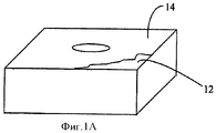
на фиг.1А представлена режущая пластина обобщенной формы с покрытием в соответствии с настоящим изобретением;on figa presents a cutting insert of a generalized form with a coating in accordance with the present invention;
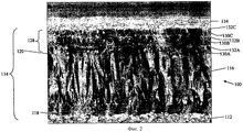
на фиг.2 представлена SEM (сканирующий электронный микроскоп) микрофотография поперечного сечения экспериментального покрытия в соответствии с настоящим изобретением;figure 2 presents the SEM (scanning electron microscope) micrograph of a cross section of the experimental coating in accordance with the present invention;
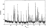
на фиг.3 представлен рентгеновский дифракционный спектр, показывающий кристаллические фазы, идентифицированные в покрытии.figure 3 presents the x-ray diffraction spectrum showing the crystalline phases identified in the coating.
ТАБЛИЦЫTABLES
В таблице 1 сведены данные о температуре, давлении и составах Газовой фазы в процессе осаждения экспериментального покрытия, показанного на фиг.2.Table 1 summarizes the data on the temperature, pressure and composition of the gas phase during the deposition of the experimental coating shown in figure 2.
ДЕТАЛЬНОЕ ОПИСАНИЕ ИЗОБРЕТЕНИЯDETAILED DESCRIPTION OF THE INVENTION
Существует ряд CVD технологий, предназначенных для осаждения Al2O3 (известного также, как оксид алюминия или корунд). Парообразная фаза включает, как правило, легкоиспаряющиеся газы, химически реагирующие на основе с осаждением Al2O3, при этом другие продукты реакции являются газообразными и отводятся. При использовании обычного термического CVD для осаждения Al2O3 требуется температура свыше 1000°С. Процесс CVD с использованием плазмы позволяет наносить такие покрытия при температурах ниже 900°С. В таком процессе химические компоненты декомпозируются и реагируют друг с другом с использованием плазменного разряда и нагрева. В результате очень чистые пленки оксида алюминия могут быть образованы на поверхности основы. Обычно используемый CVD процесс включает коррозионный реагент AlCl3. Использование газовой смеси AlCl3/CO2/H2 при низком давлении приводит в результате к преимущественному росту столбчатой структуры покрытия по сравнению с равноосной. Газовая смесь AlCl3/CO2/Н2 при атмосферном давлении может привести к росту больших зерен.There are a number of CVD technologies designed to precipitate Al 2 O 3 (also known as alumina or corundum). The vapor phase includes, as a rule, volatile gases chemically reacting on the basis with the precipitation of Al 2 O 3 , while other reaction products are gaseous and are discharged. When using conventional thermal CVD, precipitation of Al 2 O 3 requires temperatures above 1000 ° C. The plasma CVD process allows such coatings to be applied at temperatures below 900 ° C. In this process, the chemical components are decomposed and react with each other using plasma discharge and heating. As a result, very pure alumina films can be formed on the surface of the substrate. A commonly used CVD process includes the corrosive reagent AlCl 3 . The use of a gas mixture of AlCl 3 / CO 2 / H 2 at low pressure results in the predominant growth of the columnar structure of the coating compared to equiaxial. A gas mixture of AlCl 3 / CO 2 / H 2 at atmospheric pressure can lead to the growth of large grains.
Алюминий три-изопропилат является другим исходным веществом, которое может быть использовано для осаждения α-оксида алюминия. Другая технология включает реактивное напыление алюминиевых мишеней в аргоно-кислородной плазме.Aluminum tri-isopropylate is another starting material that can be used to precipitate α-alumina. Another technology involves reactive sputtering of aluminum targets in argon-oxygen plasma.
Алюминий ацетилацетонат также может быть использован как исходное вещество для металлоорганического химического осаждения оксида алюминия из парообразной фазы при атмосферном давлении (см. «MOCVD of Aluminium Oxide Barrier Coating», автор Jan С.Nable и др., J. Phys. IV France 12 (2002) Pr 4-139.Aluminum acetylacetonate can also be used as a starting material for the organometallic chemical deposition of aluminum oxide from the vapor phase at atmospheric pressure (see "MOCVD of Aluminum Oxide Barrier Coating," by Jan C. Nable et al., J. Phys. IV France 12 ( 2002) Pr 4-139.
Алюминий трис-тетраметил-гептандионат [Al(thd)3] и алюминий трис-ацетилацетонат [Al(асас)3] также могут быть использованы для осаждения пленок Al2O3 по технологии CVD (см. «Diketonates as Precussors MOCVD of Aluminium Oxide Films Using Aluminium», авторы A.Devi, S.A.Shivashankar и A.G.Samuelson).Aluminum tris-tetramethyl heptanedionate [Al (thd) 3] and aluminum tris-acetylacetonate [Al (acac) 3] can also be used to precipitate Al 2 O 3 films using CVD technology (see Diketonates as Precussors MOCVD of Aluminum Oxide Films Using Aluminum ”, authors A.Devi, SAShivashankar and AGSamuelson).
Еще одной технологией осаждения тонких пленок алюминия является пиролиз исходного вещества в виде алюминий ацетилацетонат, который может быть выполнен при относительно низкой температуре, например 435-550°С.Another technology for the deposition of thin aluminum films is the pyrolysis of the starting material in the form of aluminum acetylacetonate, which can be performed at a relatively low temperature, for example 435-550 ° C.
При высоких температурах рост зерна преобладает над зарождением новых зерен и осаждение α-оксида алюминия посредством CVD технологии приводит в результате к относительно грубой столбчатой структуре, характеризующейся острыми границами между соседними кристаллами и слабым межкристаллическим взаимодействием. Соответственно, такие покрытия α-оксида алюминия проявляют чувствительность к распространению трещин по толщине покрытия. Температура осаждения не является единственным параметром, влияющим на рост зерна и скорость зарождения новых зерен, другие параметры, такие как парциальные давления реагентов, температура основы, использование H2S или других катализаторов, могут влиять на результирующую микроструктуру и их изменение является средством контроля особенностей получаемых таким образом покрытий.At high temperatures, grain growth prevails over the nucleation of new grains and the deposition of α-alumina by CVD technology results in a relatively rough columnar structure characterized by sharp boundaries between adjacent crystals and weak intercrystalline interaction. Accordingly, such α-alumina coatings exhibit sensitivity to crack propagation throughout the coating thickness. The deposition temperature is not the only parameter affecting grain growth and the rate of nucleation of new grains, other parameters, such as partial pressure of reagents, base temperature, the use of H 2 S or other catalysts, can affect the resulting microstructure and their change is a means of controlling the characteristics of the obtained thus coatings.
Характерной особенностью предпочтительных вариантов настоящего изобретения, как описано ниже, является толстое с хорошим сцеплением многослойное покрытие α-оксида алюминия, имеющее тонкую микроструктуру равноосных зерен. Это достигается попеременным осаждением подслоев оксида алюминия и промежуточных слоев второго материала, имеющего хорошую адгезию с подслоем α-оксида алюминия, такого как, например TiAlCON, TiAlON или TiAlOC, предположительно в виде твердого раствора алюминия TiCON, TiON или TiOC соответственно. Второй слой наносится путем химического осаждения из парообразной фазы из смеси TiCl4, ALCl3, N2, CH4, Н2, СО2 и H2S. При этом осаждение α-оксида алюминия периодически прерывается осаждением очень тонких слоев второго материала, который как прерывает рост зерен предыдущего слоя, так и обеспечивает точки для образования новых кристаллов α-оксида алюминия в новом подслое, и наращивается многослойная структура α-оксида алюминия. Таким образом, промежуточный слой второго материала, образованный непосредственно после слоя α-оксида алюминия, предшествует развитию столбчатой структуры в этом слое. Посредством этого предотвращается направленный рост толстого α-оксида алюминия, что значительно уменьшает склонность керамического покрытия к распространению трещин.A characteristic feature of the preferred embodiments of the present invention, as described below, is a thick, well-bonded α-alumina multilayer coating having a fine microstructure of equiaxed grains. This is achieved by alternately precipitating alumina sublayers and intermediate layers of a second material having good adhesion to the α-alumina sublayer, such as, for example, TiAlCON, TiAlON or TiAlOC, presumably in the form of a solid solution of aluminum TiCON, TiON or TiOC, respectively. The second layer is deposited by chemical vapor deposition from a mixture of TiCl 4 , ALCl 3 , N 2 , CH 4 , H 2 , CO 2 and H 2 S. Moreover, the deposition of α-alumina is periodically interrupted by the deposition of very thin layers of the second material, which as it interrupts the grain growth of the previous layer, it provides points for the formation of new crystals of α-alumina in a new sublayer, and the multilayer structure of α-alumina grows. Thus, the intermediate layer of the second material formed immediately after the α-alumina layer precedes the development of the columnar structure in this layer. This prevents the directional growth of thick α-alumina, which significantly reduces the tendency of the ceramic coating to crack propagation.
Следует отметить, что в отличие от системы, описанной в US 20020176755 A1, и большинства других износостойких покрытий оксидом алюминия, система покрытия в предпочтительных вариантах относится к α-оксида алюминия, а не к к-Al2O3 или к γ-Al2O3. Следует подчеркнуть, что, будучи стабильной аллотропной модификацией, α-оксид алюминия является также плотной аллотропной модификацией (его плотность составляет свыше 4 г/см3 против менее 3,6-3,8 г/см3 для других аллотропных модификаций). Установлено, что в условиях давление-температура, возникающих в процессе операций обработки резанием, α-оксид алюминия обладает большей вязкостью, чем другие аллотропные модификации, и имеет возможность пластического деформирования для снятия напряжений. Кроме того, установлено, что промежуточные слои второго материала обладают хорошим сцеплением с оксидом алюминия с обеспечением высокой целостности покрытия. Предположительно, промежуточный слой второго материала создает высокую плотность точек для образования новых кристаллов Al2O3, что приводит в результате к большому числу малых кристаллов. Предположительно также, наличие как Al, так и О во втором материале промежуточных слоев обеспечивает химическое соединение Al и О в Al2O3 и обеспечивает также точки зарождения новых зерен, приводящие к большей плотности зерен оксида алюминия и росту числа малых зерен.It should be noted that, unlike the system described in US 20020176755 A1, and most other wear-resistant alumina coatings, the coating system in the preferred embodiments relates to α-alumina rather than k-Al 2 O 3 or γ-Al 2 O 3 . It should be emphasized that, being a stable allotropic modification, α-alumina is also a dense allotropic modification (its density is over 4 g / cm 3 versus less than 3.6-3.8 g / cm 3 for other allotropic modifications). It has been established that under pressure-temperature conditions arising during cutting operations, α-alumina has a higher viscosity than other allotropic modifications, and has the possibility of plastic deformation to relieve stresses. In addition, it was found that the intermediate layers of the second material have good adhesion to alumina with high coating integrity. Presumably, the intermediate layer of the second material creates a high density of dots for the formation of new Al 2 O 3 crystals, resulting in a large number of small crystals. Presumably, the presence of both Al and O in the second material of the intermediate layers provides a chemical compound of Al and O in Al 2 O 3 and also provides the nucleation points of new grains, leading to a higher density of alumina grains and an increase in the number of small grains.
Рассмотрим теперь фиг.1, на которой схематически представлено поперечное сечение слоев покрытия на пластине 10. Как видно на фиг.1 А, пластина 10 состоит из непокрытого корпуса или основы 12 и многослойного покрытия 14. Основа 12 может быть выполнена из сплава на основе быстрорежущей стали, содержащего в дополнение к железу и углероду различные количества тугоплавких металлов, таких как, например, хром, вольфрам, молибден и титан. Альтернативно основа 12 может быть выполнена из керамики, такой как Si3N4, Al2O3, Al2O3/TiC, SiAlON, Al2O3/SiC композит с нитевидными кристаллами и другие. Более подходящим является выполнение основы 12 из композита типа кермета, такого как TiC или TiN в металлической связке. Однако наиболее подходящим является выполнение основы 12 в виде твердого сплава, включающего карбид вольфрама (WC) и дополнительные карбиды, соединенные в металлической матрице, часто в виде кобальта (Co), обозначенного ниже как вольфрамовый твердый сплав. Твердые сплавы описаны на с.321 "Tungsten Properties, Chemistry, Technology of the Element, Alloys, and Chemical compounds", опубликованного Kluwer Academic/Plenum Publishers в 1999. Непокрытая основа 12 может быть выполнена из любого из выше упомянутых материалов и в дальнейшем будет обозначаться как основа 12.Let us now consider figure 1, which schematically shows the cross section of the coating layers on the plate 10. As can be seen in figure 1 A, the plate 10 consists of an uncoated body or
Как правило, основа 12 подготавливается путем обезжиривания, пескоструйной обработки и очистки в ультразвуковой ванне перед осаждением на нее многослойного покрытия 14.As a rule, the
Многослойное покрытие 14 включает относительно толстый слой 16 под покрытие из первого твердого материала. Слой 16 под покрытие, как правило, имеет толщину от 4 мкм до 15 мкм и характеризуется хорошим сопротивлением износу по задней грани и вершине. Тонкий (0,1 мкм-1,5 мкм) базовый слой 18, как правило TiN, может быть осажден перед слоем 16 под покрытие.The
Базовый слой 18 позволяет использовать для пластины 10 относительно различные CVD условия, которые могут потребоваться для осаждения слоя 16 под покрытие без обезуглероживания основы 12, посредством чего минимизируется образование нежелательных хрупких η фаз (M12C, М6С, где М - Co и W), образующихся возле поверхности основы 12.The base layer 18 allows the use of relatively different CVD conditions for the plate 10, which may be required to deposit the layer 16 under the coating without decarburization of the
Тонкий связывающий слой 20 (0,1 мкм-1 мкм) осаждается на слой 16 под покрытие. Связывающий слой 20 может иметь сэндвичевую структуру, состоящую из внутреннего связывающего слоя TiAlOCN 22, расположенного между нижним связывающим слоем и верхним связывающим слоем TiOCN, 24, 26 соответственно.A thin bonding layer 20 (0.1 μm-1 μm) is deposited on the layer 16 under the coating. The
TiCON может быть осажден различными путями. Например: TiCl4+N2+H2+СН4+CO2→TiCON + хлориды и другие газы.TiCON can be precipitated in various ways. For example: TiCl 4 + N 2 + H 2 + CH 4 + CO 2 → TiCON + chlorides and other gases.
TiAlCON также может быть осажден различными путями. Например: TiCl4+N2+Н2+СН4+CO2+AlCl3→TiAlCON + хлориды и другие газы.TiAlCON can also be precipitated in various ways. For example: TiCl 4 + N 2 + H 2 + CH 4 + CO 2 + AlCl 3 → TiAlCON + chlorides and other gases.
Толстое керамическое покрытие 28 осаждено на связывающий слой 20. Керамическое покрытие 28 имеет слоистую структуру из слоев 30 оксида в виде α-Al2O3 с промежуточными слоями 32. Прежде всего осаждается первый оксидный слой 30А. Предположительно, вследствие наличия верхнего связывающего слоя 26 из TiOCN, слой 30А оксида осаждается с высокой плотностью зерна и вследствие этого малым размером зерна и хорошо сцепляется со связывающим слоем 20.A thick ceramic coating 28 is deposited on the
Промежуточный слой 32 является вторым материалом, представляющим собой твердый раствор кислорода и алюминия в матрице TiCN, TiC или TiN. Предполагается, что хорошее сцепление слоя 30 оксида с промежуточным слоем 32 является результатом взаимодействия Al и О промежуточного слоя 32 со слоем 30 оксида за счет большей кристаллической и химической совместимости промежуточного слоя 32, обеспечивающих образование на нем слоя 30 оксида.The intermediate layer 32 is the second material, which is a solid solution of oxygen and aluminum in a matrix of TiCN, TiC or TiN. It is assumed that the good adhesion of the
Если допустить неограниченный рост, зерна слоя 30 оксида, как правило становятся большими и столбчатыми. В некоторых случаях они могут иметь преобладающую ориентацию. Однако в настоящем варианте очень тонкий первый промежуточный слой 32А TiAlCON, например, осаждается на первый слой 30А оксида. Первый промежуточный слой 32А ограничивает рост зерна первого слоя 30А оксида и предположительно обеспечивает свежие точки образования и роста зерен, на которые может быть осажден второй слой 30В оксида. Затем может быть осажден второй очень тонкий промежуточный слой 32В.Assuming unlimited growth, the grains of
Путем попеременного осаждения слоев 30 оксида и промежуточных слоев 32 с помощью технологии CVD может быть получено толстое керамическое покрытие 28, имеющее равноосные зерна малого размера. Каждый промежуточный слой 32 ограничивает рост зерна предшествующего слоя 30 оксида и возможно обеспечивает также высокую плотность точек образования новых керамических кристаллов.By alternately depositing the oxide layers 30 and the intermediate layers 32, a thick ceramic coating 28 having equiaxed small grain sizes can be obtained using CVD technology. Each intermediate layer 32 limits the grain growth of the
Следует подчеркнуть, что улучшение твердости и износостойкости большинства материалов связано с уменьшением размера зерна в соответствии с эффектом Hall-Petch. Кроме того, более значимым является постоянное образование новых точек роста, ограничивающих образование толстых направленных столбчатых кристаллов, что значительно уменьшает чувствительность к распространению трещин в полученном таким образом керамическом покрытии.It should be emphasized that the improvement in hardness and wear resistance of most materials is associated with a decrease in grain size in accordance with the Hall-Petch effect. In addition, the constant formation of new growth points, limiting the formation of thick directional columnar crystals, which significantly reduces the sensitivity to crack propagation in the ceramic coating thus obtained, is more significant.
Предпочтительное количество слоев 30 оксида и промежуточных слоев 32 в керамическом покрытии 28 зависит от конструкционных критериев для каждого специфического применения. Предположительно при определенном размере состав промежуточного слоя 32, и особенно содержание Al и О в твердом растворе в промежуточном слое 32, определяет размер зерна. Следует отметить, что хотя состав промежуточного слоя 32 зависит от парциальных давлений реагирующих компонентов, прямо этим не определяется, при этом концентрация различных элементов в покрытии не изменяется соответственно изменению их концентрации в реагирующих газах.The preferred number of
В предпочтительном варианте основа 12 выполнена из вольфрамового твердого сплава, а в качестве первого материала слоя 16 под покрытие использован TiCN, который наилучшим образом проявляется в уменьшении износа по задней грани и уменьшении лунки износа. Чтобы избежать при различных условиях, необходимых для осаждения TiCN слоя 16 под покрытие, обезуглероживания основы 12, которая в противном случае может привести к образованию хрупких η фаз, предпочтительно на нее наносят базовый слой 18. Установлено, что с этой целью TiN, хорошо известный для специалистов, является подходящим вариантом для базового слоя 18.In a preferred embodiment, the
Связывающий слой 20 осажден между TiCN слоем 16 под покрытие и керамическим покрытием 28, которое составлено из чередующихся слоев 30 оксида α-Al2O3 и промежуточных слоев 32 TiAlCON, лежащих друг на друге (30А, 32А, 30В, 32В, 30С, 32С …).The
Использование TiAlCON для промежуточных слоев 32А, 32В, 32С … способствует образованию на них α-Al2O3 оксидных слоев 30В, 30С, 30D …. Установлено, что чередующиеся слои 30А, 30В, 30С … α-Al2O3 оксида и промежуточные слои 32А, 32В … имеют высокую адгезию.The use of TiAlCON for the intermediate layers 32A, 32B, 32C ... promotes the formation of α-Al 2 O 3 oxide layers 30B, 30C, 30D ... on them. It was found that alternating layers 30A, 30B, 30C ... α-Al 2 O 3 oxide and the intermediate layers 32A, 32B ... have high adhesion.
Количество оксидных 30 и промежуточных 32 слоев во многом зависит от требуемой толщины покрытия 28. В основном путем изменения рабочей температуры и парциальных давлений используемых газов активности базового слоя 18, в особенности его верхней поверхности, может быть получено преобладание зарождения оксидов 30 над ростом зерна и в результате получены зерна с меньшим размером. Предположительно также, что слои 30А, 30В, 30С … α-Al2O3 оксида являются почти полностью равноосными или в любом случае менее направленными, чем столбчатые кристаллы, образованные при непрерывном CVD.The number of
Практично, для обеспечения привлекательного внешнего вида верхний слой 34 может быть осажден на покрытие 14, описанное выше. Для этой цели может быть использован TiN, имеющий, как известно, приятный золотой цвет. Наружный слой 34 TiN может быть удален по меньшей мере на передней поверхности пластины.Practically, to provide an attractive appearance, the top layer 34 can be deposited on the
Пример 1.Example 1
Для подтверждения изложенного рассмотрим представленную на фиг.2 микрофотографию, полученную с помощью электронного сканирующего микроскопа (SEM) и показывающую поперечное сечение пластины 100, включающей основу 112 и многослойное покрытие 114 в соответствии с предпочтительным вариантом изобретения. Внизу изображения показана основа 112 из вольфрамового твердого сплава. Угловатые кристаллы карбида вольфрама имеют средний размер зерна около 1 мкм. Многослойное покрытие 114 включает тонкое базовое покрытие TiN 1128 толщиной около 1 мкм. Сверху на базовом покрытии 118 TiN был осажден относительно толстый, около 7 мкм, слой под покрытие со столбчатым TiCN. Сверху осажден связывающий слой 120, выполненный в виде системы, имеющей сэнвичевую структуру TiOCN, TiAlOCN и TiOCN, однако вследствие взаимной диффузии ослаблен контраст между различными подслоями системы и они не различимы на SEM микрофотографии.To confirm the foregoing, we consider the micrograph shown in FIG. 2 obtained by an electronic scanning microscope (SEM) and showing a cross section of a
Показано слоистое толстое керамическое покрытие 128 из чередующихся подслоев 130А, 130В и 130С оксида α-Al2O3, толщиной приблизительно 1 мкм, и промежуточных слоев 132А, 132В, 132С TiAlOCN, толщиной приблизительно 0,1 мкм. Таким образом, отношение толщин слоя оксида и промежуточного слоя составляет порядка 10. Это отношение может принимать другие значения, предпочтительно между 7 и 15, может быть виден также наружный слой 134 TiN толщиной приблизительно 0,5 мкм.A layered thick
Температура, давление и скорости потоков газов, используемых для химического осаждения, показаны в таблице 1. Эти данные обеспечивают полную возможность воспроизведения предпочтительного варианта изобретения.The temperature, pressure and flow rates of the gases used for chemical deposition are shown in Table 1. These data provide full reproducibility of the preferred embodiment of the invention.
Покрытие, показанное на фиг.2, было исследовано с помощью дифракции рентгеновских лучей (XRD) от источника Cu-Kα. На фиг.3 показан спектр дифракции рентгеновских лучей. Как хорошо известно специалистам, по вертикальной оси показано количество импульсов в секунду фотонов, регистрируемых детектором рентгеновского излучения, а по горизонтальной оси (29) - дифракционный угол (на который установлен детектор), где θ - угол отклонения рентгеновских лучей. Все главные пики имеют следующие обозначения: 1 - α-Al2O3; 2 - TiN; 3 - TiCN(MT) и 4 - WC. Как ясно показано, слои оксида состоят из α-Al2O3, другие аллотропные модификации отсутствуют. Более того, острота пиков и относительно низкий уровень шумового фона показывают, что покрытие имеет исключительно кристаллическую структуру с размером кристаллов более 100 нм.The coating shown in FIG. 2 was examined by X-ray diffraction (XRD) from a Cu-Kα source. Figure 3 shows the x-ray diffraction spectrum. As is well known to specialists, the vertical axis shows the number of pulses per second of photons detected by the X-ray detector, and the horizontal axis (29) shows the diffraction angle (at which the detector is mounted), where θ is the angle of deflection of the X-rays. All major peaks have the following notation: 1 - α-Al 2 O 3 ; 2 - TiN; 3 - TiCN (MT) and 4 - WC. As clearly shown, the oxide layers are composed of α-Al 2 O 3 , other allotropic modifications are absent. Moreover, the sharpness of the peaks and the relatively low level of background noise indicate that the coating has an exclusively crystalline structure with a crystal size of more than 100 nm.

Примеры 2-4 представляют преимущества пластин типа А (т.е. пластин, покрытых в соответствии с изобретением), которые были испытаны в идентичных условиях вместе с пластинами типа В (т.е. пластинами с известными покрытиями). Детали известного из уровня техники покрытия пластин типа В от внутреннего слоя до наружного слоя следующие: за внутренним слоем TiN толщиной приблизительно 0,6 мкм следует толстый слой TiCN MT толщиной приблизительно 6 мкм со столбчатыми зернами, полученный по технологии MT CVD. Третий слой TiN имеет толщину приблизительно 0,15 мкм, а четвертый слой TiC имеет толщину приблизительно 0,3 мкм. Пятый слой TiOCN имеет толщину приблизительно 0,1 мкм, а шестой слой α-Al2O3 имеет толщину приблизительно 3 мкм. Наружный слой TiN имеет толщину приблизительно 0,8 мкм.Examples 2-4 represent the advantages of Type A wafers (i.e., wafers coated in accordance with the invention) that were tested under identical conditions with Type B wafers (i.e. wafers with known coatings). The details of the prior art coating of type B wafers from the inner layer to the outer layer are as follows: an inner TiN layer with a thickness of approximately 0.6 μm is followed by a thick TiCN MT layer with a thickness of approximately 6 μm with columnar grains obtained by MT CVD technology. The third TiN layer has a thickness of approximately 0.15 μm, and the fourth TiC layer has a thickness of approximately 0.3 μm. The fifth layer of TiOCN has a thickness of approximately 0.1 μm, and the sixth layer of α-Al 2 O 3 has a thickness of approximately 3 μm. The outer layer of TiN has a thickness of approximately 0.8 μm.
Примеры сведены в таблицы.Examples are summarized in tables.
Пример 2Example 2
Пример 3Example 3
Пример 4.Example 4
Хотя выше приведены комбинации материалов предпочтительного варианта, возможны другие материалы и комбинации, могут быть заменены легирующие элементы.Although the combinations of materials of the preferred embodiment are given above, other materials and combinations are possible, alloying elements may be replaced.
Таким образом, объем настоящего изобретения определен в приведенной ниже формуле изобретения и включает как комбинации и подкомбинации различных особенностей, описанных выше, так и их изменения и модификации, которые становятся ясными для специалиста после ознакомления с приведенным выше описанием.Thus, the scope of the present invention is defined in the following claims and includes both combinations and subcombinations of the various features described above, and their changes and modifications that become clear to a person skilled in the art after reviewing the above description.
В формуле изобретения слово «включать» и его различные варианты, такие как «включает», «включающий» и другие, относятся к приведенным далее компонентам, но в основном не исключают других компонентов.In the claims, the word “include” and its various variants, such as “includes”, “including” and others, refer to the following components, but generally do not exclude other components.
Claims (19)
Applications Claiming Priority (2)
| Application Number | Priority Date | Filing Date | Title |
|---|---|---|---|
| IL182344A IL182344A (en) | 2007-04-01 | 2007-04-01 | Cutting insert having ceramic coating |
| IL182344 | 2007-04-01 |
Publications (2)
| Publication Number | Publication Date |
|---|---|
| RU2009136033A RU2009136033A (en) | 2011-06-20 |
| RU2456126C2 true RU2456126C2 (en) | 2012-07-20 |
Family
ID=39620212
Family Applications (1)
| Application Number | Title | Priority Date | Filing Date |
|---|---|---|---|
| RU2009136033/02A RU2456126C2 (en) | 2007-04-01 | 2008-03-06 | Cutting plate with ceramic coating |
Country Status (12)
| Country | Link |
|---|---|
| US (1) | US7887935B2 (en) |
| EP (1) | EP1980649B2 (en) |
| JP (1) | JP5269066B2 (en) |
| KR (1) | KR101274912B1 (en) |
| CN (1) | CN101652502B (en) |
| AT (1) | ATE478172T2 (en) |
| BR (1) | BRPI0809167B1 (en) |
| DE (1) | DE602008002173D1 (en) |
| IL (1) | IL182344A (en) |
| RU (1) | RU2456126C2 (en) |
| TW (1) | TW200841978A (en) |
| WO (1) | WO2008120185A1 (en) |
Cited By (4)
| Publication number | Priority date | Publication date | Assignee | Title |
|---|---|---|---|---|
| RU2613258C2 (en) * | 2012-12-27 | 2017-03-15 | Корлой Инк. | Multilayer thin film for cutting tools and cutting tools, comprising such film |
| RU2655414C2 (en) * | 2014-01-27 | 2018-05-28 | Тунгалой Корпорейшн | Coated cutting tool |
| RU2667187C2 (en) * | 2013-06-27 | 2018-09-17 | Сандвик Интеллекчуал Проперти Аб | Coated cutting tools |
| RU2682738C2 (en) * | 2014-04-30 | 2019-03-21 | ЭРЛИКОН МЕТКО (ЮЭс) ИНК. | Welded coat with titanium carbide and method for manufacture thereof |
Families Citing this family (36)
| Publication number | Priority date | Publication date | Assignee | Title |
|---|---|---|---|---|
| JP4427271B2 (en) * | 2003-04-30 | 2010-03-03 | 株式会社神戸製鋼所 | Alumina protective film and method for producing the same |
| SE528109C2 (en) * | 2004-07-12 | 2006-09-05 | Sandvik Intellectual Property | Phantom inserts, especially for phase milling of steel sheet for oil pipes, and ways of manufacturing the same |
| US8231312B2 (en) * | 2006-08-31 | 2012-07-31 | Sumitomo Electric Hardmetal Corp. | Surface-coated cutting tool |
| US20110016946A1 (en) * | 2009-07-21 | 2011-01-27 | Sudhir Brahmandam | Coated Tooling |
| US8323783B2 (en) * | 2009-11-10 | 2012-12-04 | Kennametal Inc. | Coated cutting insert and method for making the same |
| US8668982B2 (en) | 2009-11-10 | 2014-03-11 | Kennametal Inc. | Coated cutting insert and method for making the same |
| CN102373412A (en) * | 2010-08-20 | 2012-03-14 | 鸿富锦精密工业(深圳)有限公司 | Vacuum-plated part and its manufacturing method |
| KR101179255B1 (en) * | 2010-11-17 | 2012-09-03 | 한국야금 주식회사 | Surface coating layer for cutting tools |
| JP5153969B2 (en) * | 2011-04-22 | 2013-02-27 | 京セラ株式会社 | Cutting tools |
| DE202011050704U1 (en) * | 2011-07-12 | 2012-10-23 | Jongen Werkzeugtechnik Gmbh & Co. Kg | Insert for mounting in the seat of a milling tool with a polygonal upper surface |
| US8974896B2 (en) * | 2013-03-08 | 2015-03-10 | Vapor Technologies, Inc. | Coated article with dark color |
| CN105142832A (en) * | 2013-03-28 | 2015-12-09 | 钴碳化钨硬质合金公司 | Multilayer structured coatings for cutting tools |
| US9427808B2 (en) * | 2013-08-30 | 2016-08-30 | Kennametal Inc. | Refractory coatings for cutting tools |
| CN103668105B (en) * | 2013-12-31 | 2016-03-09 | 厦门金鹭特种合金有限公司 | A kind of method preparing coating on cutting inserts |
| KR20150083621A (en) * | 2014-01-10 | 2015-07-20 | 한국야금 주식회사 | Hard coated layer for cutting tools |
| JP5898394B1 (en) * | 2014-08-28 | 2016-04-06 | 京セラ株式会社 | Coated tool |
| CN106715012B (en) * | 2014-09-24 | 2018-10-23 | 京瓷株式会社 | Coated tool |
| US9719175B2 (en) * | 2014-09-30 | 2017-08-01 | Kennametal Inc. | Multilayer structured coatings for cutting tools |
| US9650712B2 (en) * | 2014-12-08 | 2017-05-16 | Kennametal Inc. | Inter-anchored multilayer refractory coatings |
| US10100405B2 (en) | 2015-04-20 | 2018-10-16 | Kennametal Inc. | CVD coated cutting insert and method of making the same |
| CN104985207A (en) * | 2015-08-07 | 2015-10-21 | 江苏塞维斯数控科技有限公司 | Portable numerical control cutting machine ceramic cutter |
| US9890084B2 (en) | 2015-10-01 | 2018-02-13 | Kennametal Inc. | Hybrid nanocomposite coatings and applications thereof |
| KR101737707B1 (en) * | 2015-12-17 | 2017-05-29 | 한국야금 주식회사 | Hard coated layer for cutting tools |
| CN105463388B (en) * | 2016-02-11 | 2018-01-19 | 广东工业大学 | Alumina series composite coating, the gradient ultra-fine cemented carbide cutter with the composite coating and preparation method thereof |
| JP6905807B2 (en) * | 2016-08-29 | 2021-07-21 | 三菱マテリアル株式会社 | Surface coating cutting tool with excellent chipping resistance and peeling resistance with a hard coating layer |
| US11292066B2 (en) * | 2017-01-16 | 2022-04-05 | Osg Corporation | Tool having a boron doped diamond coating |
| CN110637105B (en) * | 2017-06-07 | 2022-03-04 | 山特维克知识产权股份有限公司 | Coated cutting tool |
| JP7087441B2 (en) * | 2018-02-27 | 2022-06-21 | 株式会社ジェイテクト | Cutting method |
| US11274366B2 (en) | 2018-03-22 | 2022-03-15 | Sumitomo Electric Hardmetal Corp. | Surface-coated cutting tool and method for manufacturing same |
| JP6565093B1 (en) | 2018-03-22 | 2019-08-28 | 住友電工ハードメタル株式会社 | Surface-coated cutting tool and manufacturing method thereof |
| JP6583762B1 (en) | 2018-03-22 | 2019-10-02 | 住友電工ハードメタル株式会社 | Surface-coated cutting tool and manufacturing method thereof |
| US11628503B2 (en) | 2018-06-28 | 2023-04-18 | Ab Sandvik Coromant | Coated cutting tool |
| EP3670699A1 (en) * | 2018-12-20 | 2020-06-24 | AB Sandvik Coromant | Coated cutting tool |
| CN110670019B (en) * | 2019-10-14 | 2021-04-02 | 四川大学 | Anti-crater wear aluminum-titanium-zirconium-nitrogen and aluminum oxide multilayer composite coating and preparation method thereof |
| EP3828311A1 (en) * | 2019-11-28 | 2021-06-02 | BIC-Violex S.A. | Razor blade coating |
| CN113584459B (en) * | 2021-08-03 | 2023-09-22 | 赣州澳克泰工具技术有限公司 | Texture enhanced kappa-Al 2 O 3 Coated tool and method for producing the same |
Citations (3)
| Publication number | Priority date | Publication date | Assignee | Title |
|---|---|---|---|---|
| RU2130823C1 (en) * | 1993-12-23 | 1999-05-27 | Сандвик Аб | Cutting tool and method for applying coat onto it |
| RU2131330C1 (en) * | 1994-01-14 | 1999-06-10 | Сандвик Аб | Cutting tool with oxide coating |
| WO2006072288A2 (en) * | 2004-12-30 | 2006-07-13 | Walter Ag | Al2o3 multilayer plate |
Family Cites Families (17)
| Publication number | Priority date | Publication date | Assignee | Title |
|---|---|---|---|---|
| JPS60238481A (en) * | 1984-05-14 | 1985-11-27 | Sumitomo Electric Ind Ltd | Multilayered coated hard metal |
| EP0408535B1 (en) † | 1989-07-13 | 1994-04-06 | Seco Tools Ab | Multi-oxide coated carbide body and method of producing the same |
| US5576093A (en) * | 1992-10-22 | 1996-11-19 | Mitsubishi Materials Corporation | Multilayer coated hard alloy cutting tool |
| US5372873A (en) | 1992-10-22 | 1994-12-13 | Mitsubishi Materials Corporation | Multilayer coated hard alloy cutting tool |
| ATE210743T1 (en) † | 1995-02-17 | 2001-12-15 | Seco Tools Ab | SINTERED CARBIDE SUBSTRATE WITH MULTI-LAYERS OF ALUMINUM |
| JP3367311B2 (en) * | 1995-12-26 | 2003-01-14 | 三菱マテリアル株式会社 | Surface-coated tungsten carbide based cemented carbide cutting tool with excellent fracture resistance with hard coating layer |
| US6071601A (en) * | 1997-05-12 | 2000-06-06 | Mitsubishi Materials Corporation | Coated cutting tool member |
| JP3266047B2 (en) | 1997-05-12 | 2002-03-18 | 三菱マテリアル株式会社 | Surface coated cemented carbide cutting tool with excellent interlayer adhesion with hard coating layer |
| SE518134C2 (en) * | 1997-12-10 | 2002-09-03 | Sandvik Ab | Multilayer coated cutting tool |
| EP0980917B1 (en) * | 1998-07-29 | 2002-07-03 | Toshiba Tungaloy Co., Ltd. | Aluminium oxide-coated tool member |
| DE19962056A1 (en) * | 1999-12-22 | 2001-07-12 | Walter Ag | Cutting tool with multi-layer, wear-resistant coating |
| US6689450B2 (en) | 2001-03-27 | 2004-02-10 | Seco Tools Ab | Enhanced Al2O3-Ti(C,N) multi-coating deposited at low temperature |
| US6733874B2 (en) * | 2001-08-31 | 2004-05-11 | Mitsubishi Materials Corporation | Surface-coated carbide alloy cutting tool |
| JP2004188575A (en) | 2002-06-28 | 2004-07-08 | Mitsubishi Materials Corp | Cutting tool of surface-coated cermet with hard coating layer having excellent thermal shock resistance |
| SE526603C3 (en) * | 2003-01-24 | 2005-11-16 | Sandvik Intellectual Property | Coated cemented carbide insert |
| JP2006334757A (en) * | 2005-06-06 | 2006-12-14 | Mitsubishi Materials Corp | Surface coated cermet cutting tool whose hard coating layer exhibits excellent wear resistance in high-speed cutting |
| US8080312B2 (en) † | 2006-06-22 | 2011-12-20 | Kennametal Inc. | CVD coating scheme including alumina and/or titanium-containing materials and method of making the same |
-
2007
- 2007-04-01 IL IL182344A patent/IL182344A/en active IP Right Grant
- 2007-04-23 TW TW096114263A patent/TW200841978A/en unknown
-
2008
- 2008-03-04 US US12/041,843 patent/US7887935B2/en active Active
- 2008-03-06 WO PCT/IL2008/000301 patent/WO2008120185A1/en active Application Filing
- 2008-03-06 RU RU2009136033/02A patent/RU2456126C2/en active
- 2008-03-06 BR BRPI0809167-6A patent/BRPI0809167B1/en active IP Right Grant
- 2008-03-06 JP JP2010501663A patent/JP5269066B2/en active Active
- 2008-03-06 KR KR1020097020473A patent/KR101274912B1/en active IP Right Grant
- 2008-03-06 CN CN2008800107641A patent/CN101652502B/en active Active
- 2008-03-28 AT AT08006032T patent/ATE478172T2/en active
- 2008-03-28 DE DE602008002173T patent/DE602008002173D1/en active Active
- 2008-03-28 EP EP08006032.0A patent/EP1980649B2/en active Active
Patent Citations (3)
| Publication number | Priority date | Publication date | Assignee | Title |
|---|---|---|---|---|
| RU2130823C1 (en) * | 1993-12-23 | 1999-05-27 | Сандвик Аб | Cutting tool and method for applying coat onto it |
| RU2131330C1 (en) * | 1994-01-14 | 1999-06-10 | Сандвик Аб | Cutting tool with oxide coating |
| WO2006072288A2 (en) * | 2004-12-30 | 2006-07-13 | Walter Ag | Al2o3 multilayer plate |
Cited By (4)
| Publication number | Priority date | Publication date | Assignee | Title |
|---|---|---|---|---|
| RU2613258C2 (en) * | 2012-12-27 | 2017-03-15 | Корлой Инк. | Multilayer thin film for cutting tools and cutting tools, comprising such film |
| RU2667187C2 (en) * | 2013-06-27 | 2018-09-17 | Сандвик Интеллекчуал Проперти Аб | Coated cutting tools |
| RU2655414C2 (en) * | 2014-01-27 | 2018-05-28 | Тунгалой Корпорейшн | Coated cutting tool |
| RU2682738C2 (en) * | 2014-04-30 | 2019-03-21 | ЭРЛИКОН МЕТКО (ЮЭс) ИНК. | Welded coat with titanium carbide and method for manufacture thereof |
Also Published As
| Publication number | Publication date |
|---|---|
| US20080240876A1 (en) | 2008-10-02 |
| BRPI0809167A2 (en) | 2014-09-16 |
| CN101652502B (en) | 2013-01-02 |
| JP5269066B2 (en) | 2013-08-21 |
| DE602008002173D1 (en) | 2010-09-30 |
| BRPI0809167B1 (en) | 2022-04-12 |
| IL182344A (en) | 2011-07-31 |
| KR20100014705A (en) | 2010-02-10 |
| US7887935B2 (en) | 2011-02-15 |
| JP2010523351A (en) | 2010-07-15 |
| EP1980649A1 (en) | 2008-10-15 |
| TW200841978A (en) | 2008-11-01 |
| EP1980649B1 (en) | 2010-08-18 |
| EP1980649B2 (en) | 2015-06-24 |
| WO2008120185A1 (en) | 2008-10-09 |
| CN101652502A (en) | 2010-02-17 |
| KR101274912B1 (en) | 2013-06-14 |
| IL182344A0 (en) | 2008-01-20 |
| RU2009136033A (en) | 2011-06-20 |
| ATE478172T2 (en) | 2010-09-15 |
Similar Documents
| Publication | Publication Date | Title |
|---|---|---|
| RU2456126C2 (en) | Cutting plate with ceramic coating | |
| JP3678924B2 (en) | Aluminum oxide coated tool | |
| JP4312989B2 (en) | α Alumina coated cutting tool | |
| JP4593852B2 (en) | Coated hard alloy | |
| EP1655388B2 (en) | Alumina layer with controlled texture | |
| EP1528125B1 (en) | Coated cutting insert for rough turning | |
| US20040144302A1 (en) | Oxide coated cutting tool | |
| CN1278307A (en) | PVD aluminium oxide (s) coated cutting tool | |
| JP4786800B2 (en) | Cutting tool coated with PVD- | |
| SE514737C2 (en) | Coated carbide cutting tool | |
| EP1953269A1 (en) | Improved alumina coated grade | |
| JP3384110B2 (en) | Coated cutting tool and its manufacturing method | |
| JP4761335B2 (en) | Method for producing TiZr carbonitride coated tool | |
| JP3910881B2 (en) | Oxide coating tool | |
| IL149884A (en) | Oxide coated cutting tool | |
| JP4107433B2 (en) | α-type aluminum oxide coated member | |
| JP4562401B2 (en) | Surface coated cutting tool | |
| JP2002273607A (en) | Multilayer coat tool | |
| EP3124144B1 (en) | Coated cutting tool | |
| JP2000218409A (en) | Surface coated cemented carbide cutting tool having hard coated layer of good defect resistance | |
| JPH0433865B2 (en) | ||
| JPH10310877A (en) | Cutting tool made of surface-coated cemented carbide in which hard coating layer has excellent interlayer adhesion | |
| JP2002205204A (en) | Multilayer covering tool | |
| JP4565464B2 (en) | Covering member | |
| JP2000024808A (en) | Covered cemented carbide cutting tool |