RU2453103C1 - Threshing device - Google Patents
Threshing device Download PDFInfo
- Publication number
- RU2453103C1 RU2453103C1 RU2010144275/13A RU2010144275A RU2453103C1 RU 2453103 C1 RU2453103 C1 RU 2453103C1 RU 2010144275/13 A RU2010144275/13 A RU 2010144275/13A RU 2010144275 A RU2010144275 A RU 2010144275A RU 2453103 C1 RU2453103 C1 RU 2453103C1
- Authority
- RU
- Russia
- Prior art keywords
- teeth
- drum
- threshing
- grain
- threshing device
- Prior art date
Links
- 230000000694 effects Effects 0.000 abstract description 2
- 239000000126 substance Substances 0.000 abstract 1
- 208000014674 injury Diseases 0.000 description 4
- 230000008733 trauma Effects 0.000 description 4
- 238000005265 energy consumption Methods 0.000 description 3
- 210000005069 ears Anatomy 0.000 description 2
- 230000003247 decreasing effect Effects 0.000 description 1
- 238000002955 isolation Methods 0.000 description 1
- 230000003144 traumatizing effect Effects 0.000 description 1
Images
Landscapes
- Threshing Machine Elements (AREA)
Abstract
Description
Изобретение относится к сельскохозяйственному машиностроению, в частности к молотильным устройствам для обмолота сельскохозяйственных культур.The invention relates to agricultural machinery, in particular to threshing devices for threshing crops.
Известно молотильное устройство (пат. РФ №2377761, A01F 12/18), содержащее молотильный барабан, снабженный расположенными по его образующей рабочими элементами с рядами зубьев, которые расположены по винтовым линиям противоположного направления и поочередно выполнены короче, чем на остальных рабочих элементах, а вершины лежат на одной цилиндрической поверхности, причем элементы барабана, на которых закреплены рабочие элементы с более короткими зубьями, расположены на большем удалении от оси барабана, чем рабочие элементы с более длинными зубьями, рабочие поверхности (плоскости) зубьев расположены под тупым углом к образующей и вне тупого угла между ней и направлением винтовой линии, точка пересечения которых находится на основании зуба.A threshing device is known (US Pat. RF No. 2377761, A01F 12/18), comprising a threshing drum equipped with working elements arranged along its generatrix with rows of teeth located along helical lines of the opposite direction and alternately made shorter than on other working elements, and the vertices lie on one cylindrical surface, and the elements of the drum, on which the working elements with shorter teeth are fixed, are located at a greater distance from the axis of the drum than the working elements with longer teeth E, the working surface (plane) of teeth arranged at an obtuse angle to the outside and forming an obtuse angle between it and the direction of the helical line, which intersection point is on the bottom of the tooth.
Недостатком известного устройства является недостаточная эффективность при обмолоте труднообмолачиваемых культур.A disadvantage of the known device is the lack of efficiency when threshing hard-to-thaw crops.
Наиболее близким к заявленному устройству относится молотильное устройство (пат. РФ №2286046, A01F 12/18), содержащее цилиндрический молотильный барабан, снабженный расположенными по его образующей рабочими элементами с рядами изогнутых зубьев, которые поочередно выполнены короче, чем на остальных рабочих элементах, и расположенную под барабаном деку, элементы барабана, на которых закреплены рабочие элементы с более короткими зубьями, расположены на большем удалении от оси барабана, чем элементы, на которых закреплены рабочие элементы с более длинными зубьями, причем разность удаления элементов крепления от оси барабана равна разности высот соответствующих рабочих элементов.Closest to the claimed device includes a threshing device (US Pat. RF No. 2286046, A01F 12/18), containing a cylindrical threshing drum, equipped with working elements located along its generatrix with rows of curved teeth, which are alternately shorter than on the other working elements, and located under the drum deck, the elements of the drum, on which the working elements with shorter teeth are fixed, are located at a greater distance from the axis of the drum than the elements on which the working elements are fixed with more long teeth, and the difference in the removal of the fastening elements from the axis of the drum is equal to the height difference of the corresponding working elements.
Недостатком известного устройства является энергоемкость обмолота и травмирование зерна.A disadvantage of the known device is the energy consumption of threshing and trauma to the grain.
Задачей предлагаемого изобретения является снижение энергоемкости обмолота и травмирования зерна с обеспечением высокой эффективности при обмолоте всех зерновых культур (трудно- и легкообмолачиваемых).The objective of the invention is to reduce the energy intensity of threshing and traumatizing grain with high efficiency when threshing all crops (hard and easy to thresh).
Поставленная задача решается за счет того, что в молотильном устройстве, содержащем молотильный барабан, снабженный расположенными по его образующей рабочими элементами с рядами зубьев, половины количества которых расположены по винтовым линиям противоположного направления и поочередно выполнены короче, чем на остальных рабочих элементах, а вершины лежат на одной цилиндрической поверхности, и расположенную под барабаном деку, более длинные зубья расположены под углом к образующей и вне тупого угла между ней и направлением винтовой линии, точка пересечения которых находится на основании зуба, а более короткие зубья параллельны образующий.The problem is solved due to the fact that in a threshing device containing a threshing drum, equipped with working elements located along its generatrix with rows of teeth, half of which are located along helical lines in the opposite direction and are alternately shorter than on the other working elements, and the vertices lie on one cylindrical surface, and a deck located under the drum, longer teeth are located at an angle to the generatrix and outside an obtuse angle between it and the direction of the screw research institutes, the intersection point of which is located at the base of the tooth, and shorter teeth are parallel to the generatrix.
Новые существенные признакиNew significant features
1. Рабочие поверхности более длинных зубьев непараллельны рабочим поверхностям более коротких зубьев.1. The working surfaces of longer teeth are not parallel to the working surfaces of shorter teeth.
2. Под углом к оси барабана расположены рабочие поверхности только более длинных зубьев.2. The working surfaces of only longer teeth are located at an angle to the axis of the drum.
3. Рабочие поверхности более коротких зубьев параллельны оси барабана.3. The working surfaces of the shorter teeth are parallel to the axis of the drum.
Перечисленные новые существенные признаки в совокупности с известными позволяют получить технический результат во всех случаях, на которые распространяется испрашиваемый объем правовой охраны.The listed new essential features in combination with the known ones allow to obtain a technical result in all cases to which the requested amount of legal protection applies.
Технический результат - снижение энергоемкости обмолота и травмирования зерна - достигается за счет того, что при расположении рабочих поверхностей более длинных зубьев под углом к образующей и вне тупого угла между ней и направлением винтовой линии, точка пересечения которых находится на основании зуба, снижается сопротивление обмолачиваемой культуры вращению барабана и интенсивность воздействия более длинных зубьев на зерно при косом ударе зубьев по обмолачиваемой массе и проскальзывании зерна по поверхности зубьев, расположенных под углом. В то же время расположение рабочих поверхностей более коротких зубьев параллельно оси барабана обеспечивает достаточную для выделения из колосьев наиболее прочно с ними связанных зерен интенсивность воздействия на труднообмолачиваемые культуры.The technical result - reducing the energy consumption of threshing and trauma to the grain - is achieved due to the fact that when the working surfaces of longer teeth are positioned at an angle to the generatrix and outside an obtuse angle between it and the direction of the helix, the intersection point of which is located on the tooth base, the resistance of the threshed culture is reduced the rotation of the drum and the intensity of the impact of longer teeth on the grain with an oblique impact of the teeth on the threshed mass and slipping of grain on the surface of the teeth located od angle. At the same time, the location of the working surfaces of the shorter teeth parallel to the axis of the drum provides sufficient intensity for exposure to hard-to-grind crops from the ears of the most firmly bound grains.
Отличительные признаки заявляемого устройства не вытекают с очевидностью из известного уровня техники, что говорит об их соответствии изобретательскому уровню.Distinctive features of the claimed device do not follow with obviousness from the prior art, which indicates their compliance with the inventive step.
Предлагаемое устройство поясняется чертежами:The proposed device is illustrated by drawings:
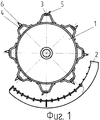
фиг.1 - схематичное изображение молотильного устройства;figure 1 is a schematic illustration of a threshing device;
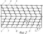
фиг.2 - развертка поверхности барабана, когда одинаково ориентированные зубья расположены на половинах цилиндрической поверхности барабана, разделенных диаметральной плоскостью;figure 2 - scan of the surface of the drum, when the equally oriented teeth are located on the halves of the cylindrical surface of the drum, separated by a diametrical plane;
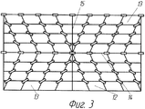
фиг.3 - развертка поверхности барабана, когда одинаково ориентированные зубья расположены на четвертях цилиндрической поверхности барабана, разделенных диаметральной плоскостью и плоскостью, перпендикулярной оси барабана и делящей его длину пополам.figure 3 - scan of the surface of the drum, when the equally oriented teeth are located on the quarters of the cylindrical surface of the drum, separated by a diametrical plane and a plane perpendicular to the axis of the drum and dividing its length in half.
Молотильное устройство содержит цилиндрический барабан 1 и решетчатую деку 2. Барабан 1 снабжен расположенными по его образующей рабочими элементами 3 и 4 с рядами зубьев 5 и 6. Зубья 5 рабочих элементов 3 выполнены более короткими, чем зубья 6 остальных рабочих элементов 4, и расположены параллельно образующей. Более длинные зубья 6 расположены под углом α к образующий и вне тупого угла β между ней и направлением винтовой линии, точка пересечения которых А находится на основании зуба. Зубья 5 и 6 расположены на барабане по винтовым линиям так, что соседние следы зубьев частично перекрывают друг друга, а вершины всех зубьев лежат на одной цилиндрической поверхности, причем половина зубьев 5 и 6 расположена по левым винтовым линиям 7, а вторая половина их - по правым винтовым линиям 8. Одинаково ориентированные более длинные зубья 6 размещены на половинах 9 и 10 цилиндрической поверхности барабана, разделенных диаметральной плоскостью со следом 11, или на четвертях соответственно 12 и 13, разделенных диаметральной плоскостью со следом 14 и плоскостью со следом 15, перпендикулярной оси барабана 1 и делящей его длину пополам. Зазор между вершинами зубьев 5 и 6 и декой 2 устанавливается постоянным или уменьшающимся от входа к выходу из молотильного устройства. Минимальный зазор должен быть несколько больше, чем максимальный размер поперечного сечения зерна.The threshing device comprises a
Молотильное устройство работает следующим образом.Threshing device operates as follows.
Подаваемая растительная масса на входе в молотильное устройство подвергается обмолоту ударами рабочих элементов 3 и 4 и отбрасывается на деку 2. На входе обмолачивается бо'льшая часть зерна. Отброшенная к поверхности деки 2 масса при продвижении ее под действием рабочих элементов барабана 1 подвергается дальнейшему обмолоту ударами и вытиранием. Благодаря различной ориентировке более длинных зубьев, расположенных по правым и левым винтовым линиям и под углом к образующей, происходит интенсивное перемещение обмолачиваемой культуры вдоль оси барабана при пониженном ее сопротивлении вращению барабана и менее интенсивном воздействии на зерно, что способствует уменьшению энергоемкости обмолота и травмирования зерна при косом ударе зубьев по хлебной массе и проскальзывании ее по поверхности развернутых зубьев, что способствует уменьшению энергоемкости и травмирования зерна. В то же время расположенные параллельно образующей более короткие зубья, оказывая более интенсивное, чем остальные зубья, воздействие на обмолачиваемую массу, обеспечивают выделение из колосьев наиболее прочно связанных с ними зерен и эффективный обмолот труднообмолачиваемых культур.The supplied plant mass at the inlet to the threshing device is threshed by impacts of working
Claims (1)
Priority Applications (1)
| Application Number | Priority Date | Filing Date | Title |
|---|---|---|---|
| RU2010144275/13A RU2453103C1 (en) | 2010-10-28 | 2010-10-28 | Threshing device |
Applications Claiming Priority (1)
| Application Number | Priority Date | Filing Date | Title |
|---|---|---|---|
| RU2010144275/13A RU2453103C1 (en) | 2010-10-28 | 2010-10-28 | Threshing device |
Publications (2)
| Publication Number | Publication Date |
|---|---|
| RU2010144275A RU2010144275A (en) | 2012-05-10 |
| RU2453103C1 true RU2453103C1 (en) | 2012-06-20 |
Family
ID=46311834
Family Applications (1)
| Application Number | Title | Priority Date | Filing Date |
|---|---|---|---|
| RU2010144275/13A RU2453103C1 (en) | 2010-10-28 | 2010-10-28 | Threshing device |
Country Status (1)
| Country | Link |
|---|---|
| RU (1) | RU2453103C1 (en) |
Citations (6)
| Publication number | Priority date | Publication date | Assignee | Title |
|---|---|---|---|---|
| US5125871A (en) * | 1991-05-21 | 1992-06-30 | Gorden Marvin J | Axial flow combine rotor having helical extension members in forward threshing area |
| RU2222138C2 (en) * | 2002-03-26 | 2004-01-27 | Липовский Марат Исаакович | Threshing unit |
| RU2238630C2 (en) * | 2002-10-15 | 2004-10-27 | Северо-Западный научно-исследовательский институт механизации и электрификации сельского хозяйства | Threshing apparatus |
| RU2239305C1 (en) * | 2003-04-30 | 2004-11-10 | Северо-Западный научно-исследовательский институт механизации и электрификации сельского хозяйства | Threshing device |
| RU2286046C1 (en) * | 2005-02-28 | 2006-10-27 | Северо-Западный научно-исследовательский институт механизации и электрификации сельского хозяйства | Threshing apparatus |
| RU2377761C1 (en) * | 2008-07-10 | 2010-01-10 | Государственное научное учреждение "Северо-Западный научно-исследовательский институт механизации и электрификации сельского хозяйства Российской академии сельскохозяйственных наук" (ГНУ СЗНИИМЭСХ Россельхозакадемии) | Thresher device |
-
2010
- 2010-10-28 RU RU2010144275/13A patent/RU2453103C1/en not_active IP Right Cessation
Patent Citations (6)
| Publication number | Priority date | Publication date | Assignee | Title |
|---|---|---|---|---|
| US5125871A (en) * | 1991-05-21 | 1992-06-30 | Gorden Marvin J | Axial flow combine rotor having helical extension members in forward threshing area |
| RU2222138C2 (en) * | 2002-03-26 | 2004-01-27 | Липовский Марат Исаакович | Threshing unit |
| RU2238630C2 (en) * | 2002-10-15 | 2004-10-27 | Северо-Западный научно-исследовательский институт механизации и электрификации сельского хозяйства | Threshing apparatus |
| RU2239305C1 (en) * | 2003-04-30 | 2004-11-10 | Северо-Западный научно-исследовательский институт механизации и электрификации сельского хозяйства | Threshing device |
| RU2286046C1 (en) * | 2005-02-28 | 2006-10-27 | Северо-Западный научно-исследовательский институт механизации и электрификации сельского хозяйства | Threshing apparatus |
| RU2377761C1 (en) * | 2008-07-10 | 2010-01-10 | Государственное научное учреждение "Северо-Западный научно-исследовательский институт механизации и электрификации сельского хозяйства Российской академии сельскохозяйственных наук" (ГНУ СЗНИИМЭСХ Россельхозакадемии) | Thresher device |
Also Published As
| Publication number | Publication date |
|---|---|
| RU2010144275A (en) | 2012-05-10 |
Similar Documents
| Publication | Publication Date | Title |
|---|---|---|
| RU2400050C1 (en) | Multi-purpose thrashing drum | |
| CN202799712U (en) | Threshing cylinder of full-feeding combine harvester | |
| RU2565262C2 (en) | Header for stripping of standing crops | |
| RU2462018C1 (en) | Cutter for spike stripping | |
| RU2490861C1 (en) | Threshing drum | |
| RU166028U1 (en) | Threshing Drum | |
| RU2479194C2 (en) | Threshing device (versions) | |
| RU168996U1 (en) | UNIVERSAL THRESHING DRUM | |
| RU2400049C1 (en) | Multi-purpose thrashing drum | |
| RU2453103C1 (en) | Threshing device | |
| RU2493692C1 (en) | Beater drum | |
| RU2222138C2 (en) | Threshing unit | |
| RU2545556C1 (en) | Combine for harvesting grain | |
| RU2694495C2 (en) | Threshing-separating device | |
| RU2238630C2 (en) | Threshing apparatus | |
| RU2281642C2 (en) | Method for threshing of cereals and apparatus for performing the same | |
| RU2377761C1 (en) | Thresher device | |
| RU189812U1 (en) | CHILDREN'S DRUM | |
| RU2351115C1 (en) | Method of thrashing grain crops using double-drum threshing-separating device and device to this end | |
| RU142926U1 (en) | THRESHING DEVICE | |
| RU142769U1 (en) | UNIVERSAL THRESHING DRUM | |
| CN203608585U (en) | A staggered arrangement of threshing drums | |
| RU168995U1 (en) | Threshing Drum | |
| RU168992U1 (en) | Threshing Drum | |
| RU167907U1 (en) | Threshing Drum |
Legal Events
| Date | Code | Title | Description |
|---|---|---|---|
| MM4A | The patent is invalid due to non-payment of fees |
Effective date: 20141029 |