RU2448369C2 - Scheme for variable packing and binding in graphics systems - Google Patents
Scheme for variable packing and binding in graphics systems Download PDFInfo
- Publication number
- RU2448369C2 RU2448369C2 RU2010107218/08A RU2010107218A RU2448369C2 RU 2448369 C2 RU2448369 C2 RU 2448369C2 RU 2010107218/08 A RU2010107218/08 A RU 2010107218/08A RU 2010107218 A RU2010107218 A RU 2010107218A RU 2448369 C2 RU2448369 C2 RU 2448369C2
- Authority
- RU
- Russia
- Prior art keywords
- variables
- program
- shadow
- register
- registers
- Prior art date
Links
Images


Classifications
-
- G—PHYSICS
- G06—COMPUTING; CALCULATING OR COUNTING
- G06T—IMAGE DATA PROCESSING OR GENERATION, IN GENERAL
- G06T1/00—General purpose image data processing
- G06T1/60—Memory management
-
- G—PHYSICS
- G06—COMPUTING; CALCULATING OR COUNTING
- G06T—IMAGE DATA PROCESSING OR GENERATION, IN GENERAL
- G06T15/00—3D [Three Dimensional] image rendering
- G06T15/005—General purpose rendering architectures
Landscapes
- Engineering & Computer Science (AREA)
- Physics & Mathematics (AREA)
- General Physics & Mathematics (AREA)
- Theoretical Computer Science (AREA)
- Computer Graphics (AREA)
- Image Generation (AREA)
- Devices For Executing Special Programs (AREA)
- Memory System Of A Hierarchy Structure (AREA)
- Complex Calculations (AREA)
Abstract
Description
УРОВЕНЬ ТЕХНИКИBACKGROUND
I. Область техникиI. Technical Field
Данное описание относится, в общем, к области обработки графики и, более конкретно, к способам для упаковки и связывания переменной в графических системах.This description relates, in General, to the field of graphics processing and, more specifically, to methods for packaging and binding a variable in graphics systems.
II. Уровень техникиII. State of the art
Общедоступный графический стандарт OpenGL или OpenGL ES имеет определенную функциональность, которая может быть сменена во время операций на вершинах и пикселах с использованием программ построения теней вершин и фрагментов. Программы построения теней вершин и фрагментов были разработаны для визуализации специальных эффектов, которые не были достигнуты стандартной функциональностью OpenGL.The openGL or OpenGL ES graphic standard has certain functionality that can be changed during operations on vertices and pixels using vertex and fragment shadowing programs. Shadow vertex and fragment shaders were designed to visualize special effects that were not achieved with the standard OpenGL functionality.
Теперь со ссылкой на фиг. 1 показана общая блок-схема стандартных стадий конвейерной обработки в устройстве обработки графики (GPU) с программами построения теней. Имеется три основных стадии конвейера: программа построения теней вершин, обозначенная в блоке S10, ассемблер примитивов и растеризатор, обозначенные в блоке S12, и программа построения теней фрагментов, обозначенная в блоке S14. Дополнительный блок S16 обеспечен для операций на выборках.Now with reference to FIG. 1 shows a general block diagram of standard pipelining stages in a graphics processing unit (GPU) with shadow building programs. There are three main stages of the pipeline: the vertex shadowing program, indicated in block S10, the primitive assembler and rasterizer, indicated in block S12, and the fragment shadowing program, indicated in block S14. An optional S16 block is provided for sampling operations.
Программа построения теней вершин (VS) S10 является программой или компьютерным программным продуктом, исполняемым для каждой вершины геометрического объекта. Входные данные VS S10 называются атрибутами, обозначенными в блоке А2. VS S10 также принимает в качестве входных данных постоянные (uniform) вершин VU2, которые могут включать в себя некоторое число постоянных вершин 0-95 (т.е. 96 постоянных вершин). Выходные данные из VS S10 и затем ассемблера примитивов и растеризатора S12 обычно называются переменными (varying), обозначенными в блоке V3, и обычно находятся в кэше вершин (хранящем выходные данные VS) или другом носителе данных (хранящем выходные данные растеризатора). Переменными V3 могут быть значения, ассоциированные с пикселами треугольников некоторого геометрического объекта. Этими значениями, ассоциированными с пикселами, являются результаты ассемблера примитивов и растеризатора S12, вычисленные на основе VS результатов, ассоциированных с вершинами треугольников некоторого геометрического объекта. Эти VS результаты, ассоциированные с этими вершинами, и переменные V3, ассоциированные с пикселами, имеют одни и те же имена или идентификаторы, типы и упорядочение. Переменные V3, ассоциированными с пикселами, являются входными данными для программы построения теней фрагментов (FS) S14. FS S14 также принимает в качестве входных данных постоянные фрагментов FU3, которые обычно включают в себя некоторое количество (например, 16) постоянных фрагментов.Vertex Shadow Builder (VS) S10 is a program or computer program product executable for each vertex of a geometric object. The input data of VS S10 is called the attributes indicated in block A2. VS S10 also accepts as input the uniform vertices of VU2, which may include a number of constant vertices 0-95 (i.e. 96 constant vertices). The output from VS S10 and then the assembler of primitives and rasterizer S12 is usually called varying, indicated in block V3, and is usually located in the vertex cache (which stores the output VS) or another storage medium (which stores the output of the rasterizer). Variables V3 can be values associated with the pixels of the triangles of some geometric object. These values associated with the pixels are the results of the assembler primitives and rasterizer S12, calculated on the basis of VS results associated with the vertices of the triangles of some geometric object. These VS results associated with these vertices and the V3 variables associated with the pixels have the same names or identifiers, types, and ordering. The variables V3 associated with the pixels are the input to the fragment shadowing program (FS) S14. FS S14 also takes as input the constants of fragments FU3, which usually include a certain number (for example, 16) of constant fragments.
Фиг. 2 показывает общую блок-схему стандартных стадий конвейерной обработки с программами построения теней. Для VS S10 внутри устройства обработки графики (GPU), обычно имеется восемь (8) регистров атрибутов RA2 для хранения атрибутов 0-7. Обычно имеется восемь выходных регистров RV3A переменной для хранения переменных 0-7. Регистры RV3А переменной сохраняют выходные данные VS, которые обычно являются кэшем вершин. Обычно имеется восемь выходных регистров RV3B переменной для хранения переменных 0-7. Регистры RV3B переменной сохраняют результаты растеризатора, соответствующие переменным, ассоциированным с пикселами. Регистры RA2 атрибутов и регистры RV3A переменной являются входными регистрами, индексированными атрибутами 0-7, и выходными регистрами RV3 переменной, индексированными переменными 0-7, соответственно. Эти идентификаторы регистров назначаются компилятором, который компилирует программу построения теней вершин и фрагментов с языка высокого уровня в машинный язык. Эти регистры, используемые в программе построения теней на языке высокого уровня, называются посредством имен вместо идентификаторов/индексов. Эти имена регистров видны только для разработчиков приложений. Приложения получают доступ к регистрам через имена регистров. Идентификаторы регистров видны только для VS S10 или FS S14 в аппаратном обеспечении (HW) GPU. Следовательно, компилятором будет создана таблица символов, такая как таблица входных символов VS, таблица выходных символов и таблица входных символов FS. Однако входные данные VS или таблица входных символов не имеют отношения к выходным данным или таблицей выходных символов в терминах содержания, идентификаторов или имен.FIG. 2 shows a general block diagram of standard pipelining stages with shadow building programs. For VS S10, inside a graphics processing unit (GPU), there are usually eight (8) RA2 attribute registers for storing attributes 0-7. Usually there are eight output registers of an RV3A variable for storing variables 0–7. The RV3A variable registers store VS output, which is usually the vertex cache. Usually there are eight output registers of an RV3B variable for storing variables 0–7. The RV3B variable registers store the rasterizer results corresponding to the variables associated with the pixels. The attribute registers RA2 and variable registers RV3A are input registers, indexed attributes 0-7, and output variable registers RV3, indexed variables 0-7, respectively. These register identifiers are assigned by the compiler, which compiles the program for constructing shadows of vertices and fragments from a high-level language to a machine language. These registers, used in a high-level language shadow program, are named by names instead of identifiers / indices. These register names are only visible to application developers. Applications access registers through register names. Register IDs are only visible for VS S10 or FS S14 in the GPU hardware (HW). Therefore, the compiler will create a symbol table, such as an input symbol table VS, an output symbol table, and an input symbol table FS. However, the input VS or the input symbol table is not related to the output or output symbol table in terms of content, identifiers or names.
Выходные данные VS или таблица выходных символов должны совпадать с входными данными или таблицей входных символов FS S14 в терминах содержания и имен, хотя входные данные или таблица входных символов FS S14 могут быть некоторым поднабором выходных данных или таблицы выходных символов VS S10.The output VS or the output symbol table must match the input data or the input symbol table FS S14 in terms of contents and names, although the input data or the input symbol table FS S14 may be some subset of the output data or the output symbol table VS S10.
VS S10 также принимает в качестве входных данных постоянные вершин VU2, хранимые в носителе данных, также как и текстуры, обозначенные как Т2, и временные переменные, обозначенные как TV2. Ассемблер примитивов и растеризатор S12 принимают переменные в выходные регистры RV3A переменной, индексированные переменными 0-7 и параметром gl_Position P. Ассемблер примитивов и растеризатор S12 выводят переменные в выходные регистры RV3B переменной, индексированные переменными 0-7 и параметром gl_Position P. FS S14 принимает в качестве входных данных постоянные фрагментов FU3, хранимые в носителе данных, также как и текстуры, обозначенные как Т3, и временные переменные, обозначенные как TV3. FS S14 принимает переменные в выходные регистры RV3B переменной, индексированные переменными 0-7 и параметром gl_Position, обозначенным как P. FS S14 также принимает дополнительные параметры gl_Frontfacing, обозначенный как FF, и gl_PointPosition, обозначенный как РР. FS S14 выводит gl_FragColor FC. Атрибуты и переменные также называются переменными программы построения теней.The VS S10 also accepts as input the constant vertices of VU2 stored in the storage medium, as well as the textures designated as T2 and temporary variables designated as TV2. The primitive assembler and rasterizer S12 accept the variables in the output registers of the RV3A variable indexed by variables 0-7 and the parameter gl_Position P. The assembler of primitives and the rasterizer S12 output variables into the output registers of the RV3B variable indexed by variables 0-7 and the parameter gl_Position P. FS S14 accepts as input, the constants of the FU3 fragments stored in the storage medium, as well as the textures designated as T3, and temporary variables designated as TV3. FS S14 accepts variables in the output registers of the RV3B variable, indexed by variables 0-7 and the parameter gl_Position, denoted by P. FS S14 also accepts additional parameters gl_Frontfacing, denoted by FF, and gl_PointPosition, denoted by PP. FS S14 outputs gl_FragColor FC. Attributes and variables are also called shadow program variables.
СУЩНОСТЬ ИЗОБРЕТЕНИЯSUMMARY OF THE INVENTION
Здесь описаны способы для упаковки и связывания переменной в графических конвейерах. Упаковка переменных программы построения теней является выгодной в мобильном GPU, так что носитель или память используется более эффективно. Упаковка переменных программы построения теней может также уменьшить полосу частот трафика, сэкономить энергию и улучшить производительность.Methods for packing and binding a variable in graphic pipelines are described herein. Packing shadow program variables is beneficial in a mobile GPU, so media or memory is used more efficiently. Packing shadow program variables can also reduce bandwidth, save energy, and improve performance.
В одной конфигурации, некоторое устройство имеет носитель данных, имеющий множество совместно используемых М-мерных (МD) регистров. Это устройство также включает в себя устройство обработки для реализации некоторого набора операций для упаковки в каждом совместно используемом MD регистре одной или нескольких переменных программы построения теней, сумма компонентов которых равна М.In one configuration, some device has a storage medium having a plurality of shared M-dimensional (MD) registers. This device also includes a processing device for implementing a certain set of operations for packaging in each shared MD register of one or more variables of the shadow-building program, the sum of the components of which is M.
В другой конфигурации, интегральная схема содержит носитель данных, имеющий множество совместно используемых М-мерных (MD) регистров. Эта интегральная схема также включает в себя устройство обработки для реализации множества операций для упаковки в каждом совместно используемом MD регистре одной или нескольких переменных программы построения теней, сумма компонентов которых равна М.In another configuration, the integrated circuit comprises a storage medium having a plurality of shared M-dimensional (MD) registers. This integrated circuit also includes a processing device for implementing a plurality of operations for packaging in each shared MD register of one or more variables of the shadow program, the sum of the components of which is M.
Еще одна конфигурация включает в себя компьютерный программный продукт. Этот компьютерный программный продукт включает в себя считываемый компьютером носитель, имеющий команды, чтобы заставить компьютер упаковывать одну или нескольких переменных из набора переменных программы построения теней, сумма компонентов которых равна М, в каждом совместно используемом М-мерном (MD) векторном регистре из множества совместно используемых MD векторных регистров.Another configuration includes a computer software product. This computer program product includes a computer-readable medium having instructions to cause a computer to pack one or more variables from a set of shadow program variables, the sum of the components of which is equal to M, in each shared M-dimensional (MD) vector register from a plurality of used MD vector registers.
Еще одна конфигурация включает в себя процессор, содержащий носитель данных, имеющий множество совместно используемых М-мерных (MD) регистров. Этот процессор также включает в себя интегральную схему для реализации набора операций для упаковки в каждом совместно используемом MD регистре одной или нескольких переменных программы построения теней, сумма компонентов которых равна М.Another configuration includes a processor comprising a storage medium having a plurality of shared M-dimensional (MD) registers. This processor also includes an integrated circuit for implementing a set of operations for packaging in each shared MD register of one or more variables of the shadow program, the sum of the components of which is M.
Дополнительные аспекты станут более ясными из подробного описания, особенно взятого вместе с прилагаемыми чертежами.Additional aspects will become more apparent from the detailed description, especially taken in conjunction with the accompanying drawings.
КРАТКОЕ ОПИСАНИЕ ЧЕРТЕЖЕЙBRIEF DESCRIPTION OF THE DRAWINGS
Аспекты и конфигурации данного описания станут более ясными из подробного описания, изложенного ниже, взятого в сопряжении с чертежами, в которых подобные ссылочные символы везде идентифицируют соответствующее.Aspects and configurations of this description will become clearer from the detailed description set forth below, taken in conjunction with the drawings, in which such reference characters everywhere identify the corresponding.
Фиг. 1 показывает общую блок-схему стандартных стадий конвейерной обработки в устройстве обработки графики с программами построения теней.FIG. 1 shows a general block diagram of standard pipelining stages in a graphics processing device with shadow building programs.
Фиг. 2 показывает общую блок-схему стандартных стадий конвейерной обработки с программами построения теней.FIG. 2 shows a general block diagram of standard pipelining stages with shadow building programs.
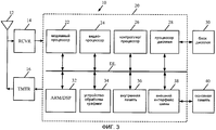
Фиг. 3 показывает блок-схему беспроводного устройства.FIG. 3 shows a block diagram of a wireless device.
Фиг. 4 показывает общую блок-схему устройства обработки графики (GPU) для программы построения теней вершин и операций упаковки.FIG. 4 shows a general block diagram of a graphics processing unit (GPU) for vertex shadowing and packaging operations.
Фиг. 5 показывает общую блок-схему устройства обработки графики (GPU) с операциями программы построения теней фрагментов и упаковки.FIG. 5 shows a general block diagram of a graphics processing unit (GPU) with operations of a fragment shadowing and packaging program.
Фиг. 6 показывает общую блок-схему драйвера.FIG. 6 shows a general block diagram of a driver.
Фиг. 7 показывает общую блок-схему двухуровневого процесса упаковки переменных программы построения теней.FIG. 7 shows a general flowchart of a two-level process for packing variables in a shadow program.
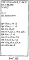
Фиг. 8А и 8В показывают программу построения теней вершин перед тем и после того, как обходные атрибуты удалены.FIG. 8A and 8B show a vertex shadowing program before and after the bypass attributes are removed.
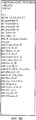
Фиг. 9А и 9В показывают другую программу построения теней вершин перед тем и после того, как обходные атрибуты удалены.FIG. 9A and 9B show another vertex shadowing program before and after the bypass attributes are removed.
Фиг. 10А и 10В показывают еще одну программу построения теней вершин перед тем и после того, как обходные атрибуты удалены.FIG. 10A and 10B show yet another vertex shadowing program before and after the bypass attributes are removed.
Фиг. 11А и 11В показывают еще одну программу построения теней вершин перед тем и после того, как обходные атрибуты удалены.FIG. 11A and 11B show yet another vertex shadowing program before and after the bypass attributes are removed.
Фиг. 12А и 12В показывают еще одну программу построения теней вершин перед тем и после того, как обходные атрибуты удалены.FIG. 12A and 12B show another vertex shadowing program before and after the bypass attributes are removed.
Фиг. 13А-13С показывают общую блок-схему процесса упаковки переменных программы построения теней, скомбинированного с обходом атрибутов.FIG. 13A-13C show a general flowchart of a process for packing variables of a shadow program combined with attribute traversal.
Фиг. 14 показывает общую блок-схему процесса связывания.FIG. 14 shows a general flowchart of the binding process.
Изображения на чертежах упрощены в иллюстративных целях и не показаны в масштабе. Для облегчения понимания, идентичные ссылочные позиции были использованы, где это возможно, для обозначения идентичных элементов, что справедливо для фигур, за исключением того, что могут быть добавлены суффиксы, когда это уместно, для дифференциации таких элементов.The images in the drawings are simplified for illustrative purposes and are not shown to scale. For ease of understanding, identical reference numerals have been used, where possible, to designate identical elements, which is true for figures, except that suffixes can be added, where appropriate, to differentiate such elements.
Прилагаемые чертежи иллюстрируют примерные конфигурации изобретения и, как таковые, не должны рассматриваться как ограничивающие объем изобретения, который может вмещать и другие равно эффективные конфигурации. Предполагается, что особенности или стадии одной конфигурации могут быть выгодно включены в другие конфигурации без дополнительного описания.The accompanying drawings illustrate exemplary configurations of the invention and, as such, should not be construed as limiting the scope of the invention, which may accommodate other equally effective configurations. It is contemplated that the features or steps of one configuration may advantageously be included in other configurations without further description.
В различных конфигурациях ниже, блоки блок-схем выполняются в изображенном порядке, или же эти блоки или их части могут выполняться одновременно, параллельно или в другом порядке.In the various configurations below, the blocks of the flowcharts are executed in the order shown, or these blocks or parts thereof can be executed simultaneously, in parallel, or in a different order.
ПОДРОБНОЕ ОПИСАНИЕDETAILED DESCRIPTION
Слово «примерный» используется здесь в значении «служащий в качестве примера, или иллюстрации». Любая конфигурация или конструкция, описанная здесь как «примерная», не должна с необходимостью толковаться как предпочтительная или преимущественная перед другими конфигурациями или конструкциями.The word "exemplary" is used here to mean "serving as an example or illustration." Any configuration or design described herein as “exemplary” should not necessarily be construed as preferred or advantageous over other configurations or structures.
Способы, описанные здесь, могут использоваться для беспроводной связи, вычисления, персональной электроники и т.д. Примерное использование этих способов для беспроводной связи описано ниже.The methods described herein can be used for wireless communications, computing, personal electronics, etc. An exemplary use of these methods for wireless communications is described below.
Фиг. 3 показывает блок-схему конфигурации беспроводного устройства 10 для использования в системе беспроводной связи. Этим беспроводным устройством может быть сотовый телефон или фотоаппарат, терминал, телефон-трубка, электронный секретарь (PDA) или некоторое другое устройство. Системой беспроводной связи может быть система множественного доступа с кодовым разделением (каналов) (CDMA), глобальная система мобильной связи (GSM) или некоторая другая система.FIG. 3 shows a configuration block diagram of a
Беспроводное устройство 10 способно обеспечить двунаправленную связь через тракт приема и тракт передачи. В тракте приема сигналы, переданные базовыми станциями, принимают антенной 12 и обеспечивают для приемника (RCVR) 14. Приемник 14 обрабатывает с заданными условиями и оцифровывает принятый сигнал и обеспечивает выборки для цифрового блока 20 для дальнейшей обработки. В тракте передачи передатчик (TMTR) 16 принимает данные, подлежащие передаче от цифрового блока 20, обрабатывает с заданными условиями эти данные и генерирует модулированный сигнал, который передают через антенну 12 к базовым станциям.The
Цифровой блок 20 включает в себя различные блоки обработки, блоки интерфейса и блоки памяти, такие как, например, модемный процессор 22, видеопроцессор 24, контроллер/процессор 26, процессор 28 дисплея, ARM/DSP 32, блок обработки графики (GPU) 34, внутреннюю память 36 и интерфейс внешней шины (EBI) 38. Модемный процессор 22 выполняет обработку для передачи и приема данных (например, кодирование, модуляцию, демодуляцию и декодирование). Видеопроцессор 24 выполняет обработку на видеоконтенте (например, неподвижных изображений, движущиеся видео и движущиеся тексты) для видеоприложений, таких как видеокамера, воспроизведение видео и организация видеоконференций. Контроллер/процессор 26 может направлять работу различных процессоров и блоков интерфейса в пределах цифрового блока 20. Процессор 28 дисплея выполняет обработку для облегчения показа видео, графики и текстов на дисплее 30. ARM/DSP 32 может выполнять различные типы обработки для беспроводного устройства 10. Блок 34 обработки графики выполняет обработку графики графического конвейера.The
Способы, описанные здесь, могут использоваться для любого из процессоров в цифровом блоке 20, например блока 34 обработки графики. Внутренняя память 36 сохраняет данные и/или команды для различных блоков в пределах цифрового блока 20. EBI 38 облегчает перенос данных между цифровым блоком 20 (например, внутренней памятью 36) и основной памятью 40 по шине или линии передачи данных DL.The methods described herein can be used for any of the processors in the
Цифровой блок 20 может быть реализован с одним или несколькими DSP (цифровыми сигнальными процессорами), микропроцессорами, RISC (процессор с сокращенным набором команд) и т.д. Цифровой блок 20 может быть также изготовлен на одной или нескольких интегральных схемах прикладной ориентации (ASIC) или некотором другом типе интегральных схем (IC).The
Способы, описанные здесь, могут быть реализованы в различных блоках аппаратного обеспечения. Например, эти способы могут быть реализованы в ASIC, DSP, RISC, ARM, устройствах обработки цифровых сигналов (DSPD), программируемых логических устройствах (PLD), программируемых пользователем вентильных матрицах (FPGA), процессорах, контроллерах, микроконтроллерах, микропроцессорах и других электронных блоках.The methods described herein may be implemented in various hardware units. For example, these methods can be implemented in ASIC, DSP, RISC, ARM, digital signal processing devices (DSPD), programmable logic devices (PLD), user programmable gate arrays (FPGAs), processors, controllers, microcontrollers, microprocessors, and other electronic units .
GPU 34 может быть также совместимым с общедоступным графическим стандартом, таким как OpenGL 2.0, OpenGL ES2.0 или D3d9.0.
Фиг. 4 показывает общую блок-схему графического устройства обработки (GPU) 34 для программы построения теней вершин и операций упаковки. GPU 34 включает в себя потоковый декодер 50, который выдает множество атрибутов в VS входной регистровый файл 56. Эти атрибуты принимаются программой построения теней вершин (VS) 60. Выходные данные VS 60 включают в себя переменные, которые хранят в VS выходном регистровом файле 57. Как можно понять, «регистровый» файл является компонентом аппаратного обеспечения, такого как носитель данных для хранения информации. В этом примере «VS входной регистровый файл» сохраняет входной файл, подлежащий посылке к VS 60. Для простоты, в большинстве случаев, при ссылке на VS входной регистровый файл 56 ссылаются на «входной файл» для VS 60 и/или аппаратное обеспечение для сохранения «входного файла». Подобным же образом, для простоты, в большинстве случаев, при ссылке на VS выходной регистровый файл 57, ссылаются на «выходной файл» из VS 60 и/или аппаратное обеспечение для сохранения «выходного файла». Как будет более подробно описано позже, эти переменные интеллектуально упаковываются компилятором 62 (фиг. 6) для упаковки переменной первого уровня. Переменные в VS выходном регистровом файле 57 посылаются к буферу 58 упаковки непрерывно сериями или в цепной последовательности, который упаковывает переменные в упаковке переменной второго уровня. Когда буфер 58 упаковки заполняется, упакованные переменные затем сохраняют в кэше 54 вершин.FIG. 4 shows a general block diagram of a graphics processing unit (GPU) 34 for a vertex shadowing program and packaging operations. The
Как будет видно из описания ниже, и VS выходной регистровый файл 57, и VS входной регистровый файл 56 включает в себя множество совместно используемых М-мерных (MD) регистров. Каждый из буферов 58 и 52 упаковки включает в себя по меньшей мере один совместно используемый М-мерный (MD) регистр.As will be seen from the description below, both the VS output register file 57 and the VS input register file 56 includes a plurality of shared M-dimensional (MD) registers. Each of the buffers 58 and 52 of the package includes at least one shared M-dimensional (MD) register.
В конфигурации фиг. 4 потоковый декодер 50 генерирует два потока, обходной поток и необходной поток. Необходной поток посылается в VS входной регистровый файл 56 и предпочтительно также упаковывается способом, показанным в Таблице 1. Обходные атрибуты упаковываются в буфере 52 упаковки. Обходные атрибуты будут подробно описаны в связи с фиг. 8А, 8В, 9А, 9В, 10А, 10В, 11А, 11В, 12А и 12В.In the configuration of FIG. 4, the stream decoder 50 generates two streams, a bypass stream and a bypass stream. The bypass stream is sent to the VS input register file 56 and is preferably also packed in the manner shown in Table 1. Bypass attributes are packed in the packing buffer 52. Bypass attributes will be described in detail in connection with FIG. 8A, 8B, 9A, 9B, 10A, 10B, 11A, 11B, 12A and 12V.
Фиг. 5 показывает общую блок-схему устройства обработки графики (GPU) с программой построения теней фрагментов и операциями связывания. Упакованные переменные хранят в кэше 54 вершин. Ассемблер примитивов и растеризатор 90 принимает в качестве входных данных переменные в кэше 54 вершин. Ассемблер примитивов и растеризатор 90 выдают упакованные переменные в буфер 92 переменной. Блок 88 связывания имеет набор команд 82 связывания, которые используются модулем 84 перераспределения и загрузки переменной. Компоновщик 80 на фиг. 6 генерирует таблицу 86 связывания, которая загружается в память для команд 82 связывания на фиг. 5 драйвером 61. Пример таблицы 86 связывания показан в Таблицах 4 и 6, изложенных ниже, который связывает упакованные переменные в таблице выходных символов VS (Таблица 2) с таблицей входных символов FS (Таблица 3). Таблица входных символов FS может иметь меньше символов, чем таблица выходных символов VS. После того как процесс связывания выполнен блоком 88 связывания, переменные из модуля 84 перераспределения и загрузки переменной посылаются в FS входной регистровый файл 79 для использования программой 70 построения теней фрагментов (FS).FIG. 5 shows a general block diagram of a graphics processing unit (GPU) with a fragment shadowing program and linking operations.
Фиг. 6 показывает общую блок-схему драйвера. Драйвер 61 включает в себя компилятор 62 и компоновщик 80. Компилятор 62 генерирует таблицу 64 входных символов VS и таблицу 66 выходных символов VS. Примерная таблица входных символов VS показана ниже в Таблице 1. Примерная таблица выходных символов VS показана ниже в Таблице 2. Компилятор 62 может назначить одному и тому же символу идентификатор в таблице 66 выходных символов, отличный от идентификатора в таблице 74 входных символов FS, так как компилятор 62 может компилировать программу 60 построения теней вершин и программу 70 построения теней фрагментов независимо. Таким образом, имеется компоновщик 80 для того, чтобы драйвер 61 осуществлял отображение между идентификаторами регистров в таблице 66 выходных символов VS и идентификаторами регистров в таблице 74 входных символов FS посредством поиска одного и того же символа в обеих таблицах. Компоновщик 80 осуществляет связь с GPU 34 для загрузки некоторой переменной (соответствующего некоторому местоположению в кэше 54 вершин или буфере 92 переменной) в соответствующий входной регистр во входном регистровом файле 79 программы 70 построения теней фрагментов для одного и того же символа переменной.FIG. 6 shows a general block diagram of a driver. The
Драйвер 61 является драйвером программного обеспечения, имеющим набор команд. Компилятор 62 и компоновщик 80 являются частями драйвера 61 программного обеспечения, запущенного на CPU 32 или контроллере/процессоре 26, тогда как GPU 34 является специальным сопроцессором, инструктируемым драйвером 61.
Таблица входных символов VS, показанная в Таблице 1, включает в себя следующие позиции: имя атрибута, тип, первоначально назначенный идентификатор входного регистра атрибута, первоначальная маска, вновь назначенный идентификатор входного регистра атрибута и новая маска. Таблица выходных символов VS, показанная в Таблице 2, включает в себя следующие позиции: имя переменной, тип, первоначально назначенный идентификатор выходного регистра переменной, первоначальная маска, вновь назначенный идентификатор выходного регистра переменной и новая маска. Маска в таблицах представляет собой достоверные компоненты для векторов атрибутов или векторов переменной, соответствующие памяти регистра стандартного MD (М=4) вектора, расположенной в аппаратном обеспечении (HW) GPU 34. Как первоначально назначенные идентификаторы и маска, так и вновь назначенные идентификаторы и маска помещены вместе в таблицах ниже просто для иллюстрации. Фактически, первоначально назначенные идентификаторы и маска могут быть временным результатом и станут вновь назначенными идентификаторами и маской посредством использования одной и той же ячейки памяти во время операций.The VS input symbol table shown in Table 1 includes the following items: attribute name, type, initially assigned attribute input register identifier, initial mask, newly assigned attribute input register identifier, and new mask. The VS output symbol table shown in Table 2 includes the following items: variable name, type, initially assigned variable output register identifier, initial mask, newly assigned variable output register identifier, and new mask. The mask in the tables represents reliable components for the attribute vectors or variable vectors corresponding to the memory of the register of the standard MD (M = 4) vector located in the hardware (HW) of the
Компилятор 62 генерирует таблицу 74 входных символов FS и выходные данные 76 FS, обозначенные как gl_FragColor FC (фиг. 2). Таблица 74 входных символов FS, показанная в Таблице 3, включает в себя следующие позиции: имя переменной, тип, первоначально назначенный идентификатор входного регистра переменной, первоначальная маска, вновь назначенный идентификатор входного регистра переменной и новая маска.The
В Таблицах 1 и 2 ниже последние два столбца заново обновляются согласно процессу упаковки, описанному позже.In Tables 1 and 2 below, the last two columns are updated again according to the packaging process described later.
Таблица входных символов VSTable 1
VS input character table
Таблица выходных символов VStable 2
VS output character table
Таблица входных символов FSTable 3
FS input character table
Таблица связывания для выходов VS и входов FSTable 4
Link table for VS outputs and FS inputs
фикатор выход-
ного регистра перемен-ной VSReappointed
output latch
variable register VS
Переменные могут быть плавающими (с плавающей точкой), двумерными (2D) векторами, трехмерными (3D) векторами, четырехмерными (4D) векторами, массивом и 2D/3D/4D матрицей и т.д. Спецификация языка построения теней OpenGL ES требует по меньшей мере 32 компонента переменной, подлежащих поддержке в мобильном GPU 34. Каждая переменная имеет различный размер и обычно занимает свое собственное пространство регистра/буфера. В кэше 54 вершин регистр обычно является 4D вектором. Кроме того, регистры, соответствующие VS входному регистровому файлу 56, и регистры, соответствующие VS выходному регистровому файлу 57, обычно являются 4D вектором. Упаковка переменной помещает различные переменные плотно вместе в непрерывном пространстве для каждой вершины или пиксела. Например, упаковка переменной, описанная здесь, помещает два 2D вектора в 4D векторный регистр. В другом примере, упаковка переменной поставит 3D вектор и плавающий (1D) в 4D векторный регистр. Без плотной их упаковки они могут храниться неплотно.Variables can be floating (floating point), two-dimensional (2D) vectors, three-dimensional (3D) vectors, four-dimensional (4D) vectors, an array and a 2D / 3D / 4D matrix, etc. The OpenGL ES shadowing language specification requires at least 32 variable components to be supported in the 34 mobile GPU. Each variable has a different size and usually takes its own register / buffer space. In a 54 vertex cache, a register is usually a 4D vector. In addition, the registers corresponding to the VS input register file 56 and the registers corresponding to the VS output register file 57 are typically a 4D vector. Variable packing puts the various variables tightly together in a continuous space for each vertex or pixel. For example, the variable packaging described here places two 2D vectors in a 4D vector register. In another example, wrapping a variable will put a 3D vector and a floating (1D) into a 4D vector register. Without their tight packing, they can be stored loosely.
Вышеприведенное описание относится к переменным. Однако, кроме переменных, могут также быть упакованы атрибуты.The above description refers to variables. However, in addition to variables, attributes can also be packed.
Фиг. 7 показывает общую блок-схему двухуровневого процесса 100 упаковки переменных программы построения теней. Процесс 100 начинается в блоке 102, где происходит интеллектуальная упаковка, инструктируемая компилятором 62. В блоке 102 две или более переменных программы построения теней, сумма компонентов которых равна М, назначаются совместно используемому М-мерному (MD) векторному регистру. Для иллюстрации, VS выходной регистровый файл 57 показан со столбцами и строками. Каждая строка имеет четыре (4) блока, обозначенных как X, Y, Z и W. За блоком 102 следует блок 104, где происходит упаковка переменных аппаратного обеспечения в буфер 58 упаковки, который упаковывает переменные программы построения теней в VS выходной регистровый файл 57 последовательно в ряд в блок NxM носителя данных кэша 54 вершин. Переменными программы построения теней фиг. 7 являются переменные.FIG. 7 shows a general flowchart of a two-
Как будет видно из описания ниже, обходные атрибуты упаковываются в буфере 52 упаковки подобно процессу блока 104, описанному в связи с фиг. 13А. Необходные атрибуты могут упаковываться с использованием процесса, описанного выше в связи с блоком 102. Таким образом, стадии процесса 100 упаковки могут использоваться для атрибутов. Следовательно, переменные программы построения теней включают в себя переменные или атрибуты.As will be seen from the description below, bypass attributes are packaged in the packaging buffer 52, similar to the process of
Первый уровень: упаковка уровня компилятораLevel one: compiler-level packaging
Следующее описание интеллектуальной упаковки в блоке 102, которая инструктируется компилятором 62, будет описана в связи с вышеприведенными Таблицами 1 и 2. Интеллектуальная упаковка применяется к переменным программы построения теней (как к переменным, так и к атрибутам). Таблица 1 иллюстрирует упаковку атрибутов, а Таблица 2 иллюстрирует упаковку переменной. Компилятор 62 выполняет упаковку необходных атрибутов или переменной посредством повторного назначения того же самого или общего MD (М-мерного) векторного регистра, имеющего ассоциированный с ним идентификатор регистра, двум или более переменным, сумма компонентов которых равна М (М=4) и обновляет маску, соответственно. MD векторный регистр для атрибутов соответствует памяти для VS входного регистрового файла 56 на фиг. 4. MD векторный регистр для переменных соответствует памяти для VS выходного регистрового файла 57 на фиг. 4. В примерной конфигурации М=4, таким образом, эти векторы обозначены как X, Y, Z и W. Тем не менее, могут использоваться другие конфигурации с большей или меньшей размерностью.The following description of smart packaging in
Маска имеет М-битовые местоположения. Таким образом, маска, ассоциированная с каждым переназначенным и/или скомбинированными атрибутами или переменными (переменными программы построения теней) для конкретного MD векторного регистра, используется для обозначения или различения, какая часть совместно используемого MD векторного регистра назначена каждому отдельному атрибуту или переменной (из комбинации) для более позднего повторного обращения и использования.The mask has M-bit locations. Thus, the mask associated with each reassigned and / or combined attributes or variables (shadow program variables) for a particular MD vector register is used to indicate or distinguish which part of the shared MD vector register is assigned to each individual attribute or variable (from a combination ) for later reuse and use.
Например, с конкретной ссылкой на Таблицу 1 выше, texcoord0 и texcoord1 были первоначально назначены различные входные регистры атрибутов, обозначенные номерами идентификаторов 3 и 4 соответственно, в столбце «Первоначально назначенный идентификатор входного регистра атрибута». Кроме того, первоначальными масками для texcoord0 и texcoord1 являются 0011 и 0011 соответственно. Компилятор 62 определяет, что как texcoord0, так и texcoord1 являются 2D векторами, и сумма этих векторов равна 4D (М=4) векторам. Следовательно, компилятор 62 инструктирует упаковку texcoord0 и texcoord1 в один и тот же регистр атрибутов, обозначенный номером идентификатора 3 в столбце «Вновь назначенный идентификатор входного регистра атрибута». Во время упаковки texcoord0 могут быть назначены местоположения наименьших значащих битов 0011 маски, и texcoord1 могут быть назначены местоположения наименьших значащих битов 0011 маски, обозначенной в столбце «Новая маска» в Таблице 1. Маска 0011 обозначает, какая часть MD векторного регистра 3 данных, соответствующих texcoord0, может быть найдена. Подобным же образом, маска 1100 обозначает, какая часть MD векторного регистра 3 данных, соответствующих texcoord1, может быть найдена. Эта номенклатура позволяет двум или более атрибутам разделять общий регистр неперекрывающимся образом. Как можно понять, число бит в маске будет изменяться в зависимости от размерности.For example, with specific reference to Table 1 above, texcoord0 and texcoord1 were initially assigned different input attribute registers, identified by identifier numbers 3 and 4, respectively, in the “Initially assigned attribute input register identifier” column. In addition, the initial masks for texcoord0 and texcoord1 are 0011 and 0011, respectively.
С конкретной ссылкой на переменные texcoord0 и texcoord1 таблицы 66 выходных символов VS, они упаковываются в один и тот же регистр переменной, имеющий номер идентификатора 0, обозначенный в столбце «Вновь назначенный идентификатор выходного регистра переменной», как наилучшим образом видно в Таблице 2. Новой маской для texcoord0 является 0011, которая является той же самой, что и старая маска. Однако новой маской для texcoord1 является 1100, которая отличается от старой маски. Таким образом, маска имеет М битов, причем каждый бит представляет некоторое местоположение в совместно используемом MD векторном регистре.With a specific reference to the variables texcoord0 and texcoord1 of table 66 of the output VS characters, they are packed into the same variable register with identifier number 0 indicated in the column “Newly assigned identifier of the output variable register”, as best seen in Table 2. New the mask for texcoord0 is 0011, which is the same as the old mask. However, the new mask for texcoord1 is 1100, which is different from the old mask. Thus, the mask has M bits, with each bit representing a location in a shared MD vector register.
В другом примере, атрибуты «Вес» и «Нормаль» таблицы 64 входных символов VS упаковываются в один и тот же регистр атрибутов, имеющий номер идентификатора 2, обозначенный в «Вновь назначенный идентификатор входного атрибута» Таблицы 1. После того как компилятор 62 инструктирует повторное назначение идентификаторов регистров и новых масок, аппаратное обеспечение (HW) GPU 34 автоматически загрузит соответствующие переменные программы построения теней (атрибуты или переменные) в назначенные регистры согласно таблицеподобным командам (с обновленными масками), которые завершают упаковку первого уровня, инструктируемую компилятором 62.In another example, the “Weight” and “Normal” attributes of the VS input symbol table 64 are packed into the same attribute register having identifier number 2 indicated in the “Newly assigned input attribute identifier” of Table 1. After the
Некоторый массив или матрица может быть логически разбита на 2D/3D/4D вектор или единственное число с плавающей точкой, затем может выполняться упаковка, инструктируемая компилятором 62. Массив может быть представлен группой плавающих чисел (чисел с плавающей точкой), 2D векторов, 3D векторов или 4D векторов. Например, массив из 10 плавающих чисел может быть разбит на два 4D вектора плюс один 2D вектор, или 10 индивидуальных плавающих чисел. Матрица 2х2 может быть разбита на два 2D вектора, матрица 3х3 - на три 3D вектора и матрица 4х4 - на четыре 4D вектора соответственно. Следовательно, компилятор 62 может инструктировать упаковку для следующих случаев: 2D вектор + 2D вектор; 3D вектор + плавающее число; 2D вектор + плавающее число [+ плавающее число]; и плавающее число + плавающее число [+ плавающее число [+ плавающее число]]. Эти примеры даны для 4D векторного регистра. Другие комбинации рассматриваются на основе числа размерностей. Использование входного регистрового файла и выходного регистрового файла может быть минимизировано посредством упаковки первого уровня.Some array or matrix can be logically divided into a 2D / 3D / 4D vector or a single floating-point number, then the packaging instructed by the
После упаковки, инструктируемой компилятором 62, все переменные программы построения теней (переменные) могут все еще не быть размещены в 4D (MD) векторы, например могут присутствовать некоторые 3D векторы, некоторые 4D векторы и т.д. В примерной конфигурации выполняется некоторый механизм для плотной HW упаковки переменных в памяти переменной или кэше 54 вершин для упаковки переменной второго уровня.After the packaging instructed by
Второй уровень: HW упаковкаSecond level: HW packaging
В памяти переменной или кэше 54 вершин все переменные для вершины или пиксела хранят в блоке NхM буфера. N является числом переменных; М=4 означает 4D векторы. Блок памяти может трактоваться как некоторое число (NxM) непрерывных (последовательных) компонентов. Для 32 битов/компонентов и М=4 эти компоненты могут быть пронумерованы 0-((Nx4)-1). Например, N=8, 8х4 блок носителя данных может трактоваться как 32 непрерывных (последовательных) компонентов, пронумерованных 0-31.In the variable memory or cache of 54 vertices, all variables for the vertex or pixel are stored in the NxM block of the buffer. N is the number of variables; M = 4 means 4D vectors. A memory block can be interpreted as a certain number (NxM) of continuous (sequential) components. For 32 bits / components and M = 4, these components can be numbered 0 - ((Nx4) -1). For example, N = 8, 8x4 data carrier block can be interpreted as 32 continuous (sequential) components, numbered 0-31.
На фиг. 4 буфер 58 упаковки представлен как 2хМ (М=4) массив слотов. Стрелки указывают направление заполнения этих слотов в буфере 58 упаковки. Верхний ряд буфера 58 упаковки обозначен как временный буфер 58А, тогда как второй ряд обозначен как рабочий буфер 58В. Таблица 5 иллюстрирует результаты HW упаковки.In FIG. 4, packing buffer 58 is represented as a 2xM (M = 4) array of slots. The arrows indicate the direction of filling these slots in the buffer 58 packaging. The top row of packing buffer 58 is designated as temporary buffer 58A, while the second row is designated as working buffer 58B. Table 5 illustrates the results of HW packaging.
Таблица 5. Упаковка при переносе из VS выходного регистрового файла в память переменной или кэш вершинTable 5. Packaging when transferring the output register file from the VS to the variable memory or vertex cache

Упаковка второго уровня может быть осуществлена в HW посредством первого заполнения последовательно в ряд временного буфера 58А (первого ряда буфера 58 упаковки). После того как временный буфер 58А окажется полным, содержимое временного буфера 58А может быть перенесено для хранения в кэш 54 вершин. В этой конфигурации буфер 58 упаковки включает в себя первый ряд из М слотов, обозначенный как временный буфер 58А, и второй ряд из М слотов, обозначенный как рабочий буфер.Second level packing can be done in the HW by first filling sequentially in a row of temporary buffer 58A (first row of packing buffer 58). After the temporary buffer 58A is complete, the contents of the temporary buffer 58A can be transferred for storage to the
С использованием примера, изложенного в Таблице 5, HW упаковка начинается со считывания переменной V0, имеющего три компонента, обозначенных как V0.x, V0.y и V0.z, из VS выходного регистрового файла 57 и последовательного заполнения слотов X, Y, Z и W временного буфера 58А (верхнего ряда) переменными V0.x, V0.y и V0.z. Как можно видеть, слот W временного буфера является свободной. Переменные V0.x, V0.y и V0.z еще не посылаются в кэш 54 вершин, пока временный буфер 58А не будет заполнен.Using the example in Table 5, HW packaging begins by reading the variable V0, which has three components, designated as V0.x, V0.y and V0.z, from the VS output register file 57 and sequentially filling the slots X, Y, Z and W of the temporary buffer 58A (upper row) with the variables V0.x, V0.y and V0.z. As you can see, slot W of the temporary buffer is free. Variables V0.x, V0.y and V0.z are not yet sent to the 54 vertex cache until the temporary buffer 58A is full.
HW упаковка продолжается посредством считывания переменной V1, имеющего четыре компонента, обозначенных как V1.x, V1.y, V1.z и V1.w, из VS выходного регистрового файла 57 и заполнения остающегося слота (слотов) во временном буфере 58А. В этом случае слот W временного буфера 58А (верхнего ряда) заполняется переменной V1.x. Оставшиеся компоненты переменной V1.y, V1.z и V1.w заполняются последовательно в слоты X, Y и Z второго ряда или рабочего буфера 58В. Когда временный буфер 58А полностью заполнен, содержимое временного буфера 58А может быть записано в (первый) ряд кэша 54 вершин для опустошения временного буфера 58А.HW packaging continues by reading the variable V1, which has four components, designated as V1.x, V1.y, V1.z and V1.w, from the VS output register file 57 and filling in the remaining slot (s) in the temporary buffer 58A. In this case, the slot W of the temporary buffer 58A (upper row) is filled with the variable V1.x. The remaining components of the variable V1.y, V1.z and V1.w are filled sequentially in slots X, Y and Z of the second row or working buffer 58B. When the temporary buffer 58A is completely full, the contents of the temporary buffer 58A can be written to the (first) row of the
Если временный буфер 58А пуст, то содержимое оставшихся компонентов переменной V1.y, V1.z и V1.w, заполненные последовательно в слоты X, Y и Z рабочего буфера 58В, переносятся во временный буфер 58А. Опять же, временный буфер 58А не является пустым. Таким образом, HW упаковка продолжается посредством считывания переменной V2, имеющего два компонента, обозначенных как V2.x и V2.y, из VS выходного регистрового файла 57 и заполнения остающегося слота (слотов) во временном буфере 58А. В этом случае слот W временного буфера 58А (верхнего ряда) заполняется переменной V2.x. Остающийся компонент V2.y переменной заполняется в слот X второго ряда или рабочего буфера 58В. Когда временный буфер 58А полностью заполнен, содержимое временного буфера 58А может быть записано во (второй) ряд кэша 54 вершин для опустошения временного буфера 58А.If the temporary buffer 58A is empty, then the contents of the remaining components of the variable V1.y, V1.z and V1.w, filled sequentially in slots X, Y and Z of the working buffer 58B, are transferred to the temporary buffer 58A. Again, the temporary buffer 58A is not empty. Thus, the HW packing continues by reading the variable V2, having two components, designated as V2.x and V2.y, from the VS output register file 57 and filling in the remaining slot (s) in the temporary buffer 58A. In this case, the slot W of the temporary buffer 58A (upper row) is filled with the variable V2.x. The remaining component of the V2.y variable is populated in slot X of the second row or working buffer 58B. When the temporary buffer 58A is completely full, the contents of the temporary buffer 58A can be written to the (second) row of the
Этот процесс продолжается для переменных в VS выходном регистровом файле 57. В этом примере, так как последняя переменная заполняет только слоты X, Y и Z временного буфера 58А, это содержимое записывается в память переменной или кэш 54 вершин с маской=xyz или (111).This process continues for the variables in the VS output register file 57. In this example, since the last variable fills only the X, Y, and Z slots of the temporary buffer 58A, this content is written to the variable's memory or 54 vertex cache with mask = xyz or (111) .
Временный буфер 58А и рабочий буфер 58В из буферов 58 упаковки готовы к работе. Когда временный буфер 58А является заполненным и готовым к выписыванию в память переменной или кэш 54 вершин, другой буфер (рабочий буфер 58В) может быть одновременно заполнен. В каждый момент времени может использоваться как шина считывания, так и шина записи для четырех (М) компонентов. Если данные одного считывания или записи меньше чем 4 компонента, то маска считывания или записи используется для указания того, какие компоненты являются достоверными для считывания или записи.The temporary buffer 58A and the working buffer 58B from the buffers 58 of the package are ready for operation. When the temporary buffer 58A is full and ready to write a variable or
После завершения HW упаковки второго уровня, идентификатор регистра, соответствующий «Вновь назначенному идентификатору выходного регистра переменной VS» в Талице 4, соответствующий упакованным переменным в таблице выходных символов VS (Таблица 2), будет изменен для соответствия памяти переменной или кэшу 54 вершин, обозначенному в столбце «Вновь назначенный идентификатор выходного регистра переменной VS» в Таблице 6. Для простоты и гибкости, отношение выходного идентификатора к местоположению в кэше 54 вершин назначается на основе единичного компонента вместо векторного регистра. Для этого примера предполагается, что texcoord0, чей идентификатор = 0, и texcoord1, чей идентификатор = 2, упаковываются в первый ряд памяти переменной или кэша 54 вершин, цвет0, чей идентификатор = 4, - во второй ряд, и цвет1, чей идентификатор = 8, - в третий ряд. Позиция и texcoord2 не используются в FS 70, таким образом, память/упаковка не распределяется для них в FS входном регистровом файле 79. Таким образом, «Вновь назначенный идентификатор входного регистра переменной FS» не обеспечен в Таблице 4 или Таблице 6.After the second level HW packaging is completed, the register identifier corresponding to the “Newly assigned VS variable output register identifier” in Table 4, corresponding to the packed variables in the VS output symbol table (Table 2), will be changed to match the variable memory or 54 vertex cache indicated in the “Newly assigned VS variable output register identifier” column in Table 6. For simplicity and flexibility, the ratio of the output identifier to the location in the 54 vertex cache is assigned on a unit-by-unit basis. th component instead of vector register. For this example, it is assumed that texcoord0, whose identifier = 0, and texcoord1, whose identifier = 2, are packed in the first row of the memory of the variable or cache of 54 vertices, color0, whose identifier = 4, is in the second row, and color1, whose identifier = 8, - in the third row. Position and texcoord2 are not used in FS 70, so memory / packing is not allocated for them in FS
HW упаковка второго уровня осуществляется посредством HW, но таблица 86 связывания, такая, как показанная в Таблице 6, обновляется компоновщиком 80 драйвера 61. Драйвер 61 способен вычислить новый идентификатор регистра/ идентификатор компонента в памяти переменной или кэше 54 вершин для каждого компонента переменной на основе одного и того же механизма упаковки и таблиц 64 и 66 входных и выходных символов VS и таблицы 74 входных символов FS и т.д. на фиг. 4. Таблица 4 иллюстрирует, что представляла бы собой таблица связывания без HW упаковки второго уровня.Second-level HW packing is done through HW, but the binding table 86, such as that shown in Table 6, is updated by
Таблица связывания для VS выходов и FS входов
после HW упаковки второго уровняTable 6
Linking table for VS outputs and FS inputs
after HW second level packaging
Обходные атрибутыWorkaround attributes
Программируемая программа построения теней вершин, такая как VS 60, является ключевым блоком вычисления в современном GPU как в игровых устройствах ПК, так и в мобильных устройствах. VS 60 является вычислительно потребляющим мощность, а также обычно узким местом работы. Однако некоторые приложения могут не использовать функциональность программы построения теней. Другим рассмотрением является то, что некоторые входные данные для VS 60 могут быть непосредственно перемещены во выходные данные без какой-либо необходимости в вычислениях.A programmable vertex shadowing program, such as the VS 60, is a key unit of computation in modern GPUs in both PC gaming devices and mobile devices. The VS 60 is computationally power hungry as well as a typically bottleneck. However, some applications may not use the functionality of the shadow builder. Another consideration is that some of the input data for the VS 60 can be directly transferred to the output without any computational need.
Простейшим решением для этих функций является пропускание всех входных данных в программу построения теней, когда программа построения теней исполняет команды перемещения. Однако такое решение будет потреблять много вычислительной мощности и вызовет уменьшение в производительности программы построения теней. Снижение производительности является результатом 1) ненужной полосы частот трафика для вводов/выводов данных; и 2) ненужных команд перемещений, выполняемых в программе построения теней.The simplest solution for these functions is to pass all input to the shadow builder when the shadow builder executes the move commands. However, such a solution will consume a lot of computing power and will cause a decrease in the performance of the shadow building program. The decrease in performance is the result of 1) an unnecessary bandwidth of traffic for data input / output; and 2) unnecessary displacement commands executed in the shader program.
Таким образом, GPU 34 построен и организован с входным трактом обхода от декодера 50 входного потока. Входной тракт обхода может идти непосредственно к кэшу 54 вершин. Драйвер 61 или компилятор 62 может определить, какие входные данные могут быть направлены непосредственно в обход к кэшу 54 вершин, и какие входные данные должны быть загружены в программу 60 построения теней. Компилятор 62 удалит все ненужные команды перемещения из программы построения теней для обходных входных данных.Thus, the
Малое логическое устройство 51 управления аппаратного обеспечения, фиктивно показанное на фиг. 4, находится в декодере 50 входного потока. Таким образом, когда принятые входные данные определены как «обход», после декодирования входного формата, эти входные данные будут посланы по обходному тракту и сохранены в кэше 54 вершин. Только те принятые входные данные, которые не обозначены как «обход», будут упакованы в VS входном регистровом файле 56 и посланы к программе 60 построения теней вершин.The small hardware control logic 51 fictitiously shown in FIG. 4, is located in the decoder 50 of the input stream. Thus, when the received input is defined as a “bypass”, after decoding the input format, this input will be sent along the bypass path and stored in a cache of 54 vertices. Only those received input data that are not designated as a “bypass” will be packed in the VS input register file 56 and sent to the vertex shadow building program 60.
В примерном варианте осуществления обходные атрибуты упаковываются в буфере 52 упаковки перед сохранением в кэше 54 вершин. Компилятор 62 будет модифицировать маску и/или идентификатор регистра способом, описанным выше в связи с буфером 58А упаковки, индекс кэша будет пропущен к кэшу 54 вершин вместе с обходными входными данными. Выходные данные из программы 60 построения теней будут иметь один и тот же идентификатор/индекс для одной и той же вершины, таким образом, кэш 54 вершин может легко синхронизировать обходные входные данные с выходными данными программы построения теней вершин.In an exemplary embodiment, workarounds are packed in packaging buffer 52 before being stored in the
Фиг. 8А и 8В показывают программу построения теней вершин перед и после удаления обходных атрибутов. Некоторые программы построения теней вершин имеют MOV команды в строках, обозначенных посредством L3 и L4. Эти MOV команды вызывают перемещение от входных регистров, ассоциированных с атрибутами, к выходным регистрам, ассоциированным с переменными. Такие атрибуты могут быть пущены в обход из программы 60 построения теней вершин. Например, на фиг. 8А, параметры v0, v1, v2 являются входными атрибутами, а oPos, oFog, oT0 и oD0 являются выходными переменными. В этом примере входной атрибут v1 в строках L1 и L3 и входной атрибут v2 в строках L2 и L4 не вовлекают каких-либо вычислений в программе 60 построения теней вершин и просто перемещаются в оТ0 и оD0. Следовательно, атрибуты v1 и v2 могут быть пущены в обход непосредственно к памяти переменной или кэшу 54 вершин перед исполнением программы (набора команд) 60 построения теней вершин. После того как атрибуты v1 и v2 пущены в обход, они не будут посланы в программу 60 построения теней вершин, обозначенную посредством удаления строк L1, L2, L3 и L4 на фиг. 8В. Кроме того, выходные переменные оТ0 и оD0 не выводятся из программы 60 построения теней вершин, обозначенной отсутствием строк L3 и L4 на фиг. 8В. Следовательно, функция обхода экономит полосу частот трафика и мощность вычисления программы построения теней вершин.FIG. 8A and 8B show a vertex shadowing program before and after removing bypass attributes. Some vertex shadowing programs have MOV commands in the lines indicated by L3 and L4. These MOV instructions cause movement from the input registers associated with the attributes to the output registers associated with the variables. Such attributes can be started bypassing from the vertex shadowing program 60. For example, in FIG. 8A, parameters v0, v1, v2 are input attributes, and oPos, oFog, oT0 and oD0 are output variables. In this example, the input attribute v1 in lines L1 and L3 and the input attribute v2 in lines L2 and L4 do not involve any calculations in the vertex shadowing program 60 and simply move to oT0 and oD0. Therefore, the attributes v1 and v2 can be started bypassing directly to the variable memory or the cache of 54 vertices before executing the program (set of instructions) 60 for constructing the shadow of the vertices. Once the attributes v1 and v2 are bypassed, they will not be sent to the vertex shadowing program 60, indicated by deleting the lines L1, L2, L3 and L4 in FIG. 8B. In addition, the output variables oT0 and oD0 are not output from the vertex shadowing program 60, indicated by the absence of lines L3 and L4 in FIG. 8B. Therefore, the bypass function saves the bandwidth of the traffic and the computational power of the vertex shadowing program.
Для обхода атрибутов, HW упаковка второго уровня настраивается, как описано ниже. Обходные атрибуты подвергаются HW упаковке второго уровня только в буфере 52 упаковки. Буфер 52 упаковки принимает обходные атрибуты от потокового декодера 50. Потоковый декодер 50 отвечает за извлечение (атрибутов) потока вершин из основной (внешней) памяти 40 и преобразования формата из различных форматов атрибутов в IEEE формат с плавающей точкой. Драйвер 61 будет связываться с потоковым декодером 50, чьи атрибуты будут пущены в обход, и чьи атрибуты будут посланы в VS входной регистровый файл 56 для программы 60 построения теней вершин. Эти обходные атрибуты будут упакованы тем же способом, что описан выше, с использованием вышеупомянутых временного буфера 58А и рабочего буфера 58В. Необходные атрибуты будут посланы и упакованы в VS входном регистровом файле 56 программы 60 построения теней вершин.To circumvent attributes, HW second-level packaging is configured as described below. Bypass attributes are exposed to second level HW packaging only in packaging buffer 52. The packing buffer 52 receives bypass attributes from the stream decoder 50. The stream decoder 50 is responsible for extracting (the attributes) of the vertex stream from the main (external)
Переменные как из обходных атрибутов, так и из VS выходного регистрового файла 57 будут заполнены во всю память переменной или кэш 54 вершин, как целый отпечаток переменной. Для упрощения, переменные из обходных атрибутов упаковываются и сохраняются в первых нескольких рядах в памяти переменной или кэше 54 вершин, а выходные данные VS, упакованные в буфере 58 упаковки, сохраняются после этого в памяти переменной или кэше 54 вершин. Например, опять со ссылкой на фиг. 8А, вывод переменной (обходной атрибут) оD0 (v2) упаковывается во временный буфер 52А буфера 52 упаковки и сохраняется в первом ряду в памяти переменной или кэше 54 вершин. Вывод переменной (обходной атрибут) оТ0 (v1) упаковывается или сохраняется в двух нижних значащих компонентах во втором ряду в памяти переменной или кэше 54 вершин. Выводы VS oPos и oFog будут упакованы или сохранены после этого, начиная с двух наиболее значащих компонентов второго ряда. В этом случае oPos.xy будет упакован в слоте zw временного буфера и затем записан во второй ряд памяти переменной или кэша 54 вершин с маской записи = zw. Таким образом, он упаковывается последовательно после оТ0 в тот же ряд, но в другие места компонентов. oPos.zw и oFog будут упакованы в рабочий буфер 52В в слоте компонентов xyz и записаны в третий ряд памяти переменной или кэша вершин с маской записи = xyz. Таблица 86 связывания будет обновлена соответственно.Variables from both the bypass attributes and the VS of the output register file 57 will be filled into the entire memory of the variable or cache of 54 vertices, as a whole fingerprint of the variable. For simplicity, variables from workarounds are packed and stored in the first few rows in the variable memory or cache of 54 vertices, and the output VS, packed in packing buffer 58, is then stored in the variable memory or cache of 54 vertices. For example, again with reference to FIG. 8A, the variable output (bypass attribute) оD0 (v2) is packed into a temporary buffer 52A of the packaging buffer 52 and stored in the first row in the variable memory or
Фиг. 9А и 9В показывают другую программу построения теней вершин перед и после удаления обходных атрибутов. Команды перемещения в строках, обозначенных стрелками L5, L6, L7, L8 и L9 могут быть обойдены. Например, в строке, обозначенной стрелкой L5, вывод переменной оТ0 (v1) может быть обойден. Другие выводы переменной оТ1 (v1), оТ2 (v3), oD0 (v4) и oD1 (v5) могут быть также обойдены. На фиг. 9В, строки, обозначенные стрелками L5, L6, L7, L8 и L9 фиг. 9А, удалены.FIG. 9A and 9B show another vertex shadowing program before and after removing bypass attributes. Move commands in the lines indicated by arrows L5, L6, L7, L8 and L9 can be bypassed. For example, in the line indicated by arrow L5, the output of the variable оТ0 (v1) can be bypassed. Other conclusions of the variable oT1 (v1), oT2 (v3), oD0 (v4) and oD1 (v5) can also be bypassed. In FIG. 9B, lines indicated by arrows L5, L6, L7, L8 and L9 of FIG. 9A deleted.
Фиг. 10А и 10В показывают еще одну программу построения теней вершин перед и после удаления обходных атрибутов. Команды перемещения в строках, обозначенных стрелками L10 и L11, могут быть обойдены. На фиг. 10В, строки, обозначенные стрелками L10 и L11 на фиг. 10А, удалены.FIG. 10A and 10B show yet another vertex shadowing program before and after removing bypass attributes. Move commands in the lines indicated by arrows L10 and L11 can be bypassed. In FIG. 10B, the lines indicated by arrows L10 and L11 in FIG. 10A removed.
Фиг. 11А и 11В показывают еще одну программу построения теней вершин перед и после удаления обходных атрибутов. Команды перемещения в строках, обозначенных стрелками L12, L13, L14, L15 и L16, могут быть обойдены. На фиг. 11В, строки, обозначенные стрелками L12, L13, L14, L15 и L16 фиг. 11А, удалены.FIG. 11A and 11B show yet another vertex shadowing program before and after removing bypass attributes. Move commands in the lines indicated by arrows L12, L13, L14, L15 and L16 can be bypassed. In FIG. 11B, the lines indicated by arrows L12, L13, L14, L15 and L16 of FIG. 11A, deleted.
Фиг. 12А и 12В показывают еще одну программу построения теней вершин перед и после удаления обходных атрибутов. Команды перемещения в строках, обозначенных стрелками L17 и L18, могут быть обойдены. На фиг. 12В, строки, обозначенные стрелками L17 и L18 фиг. 12А, удалены. Примеры, показанные на фиг. 8А, 8В, 9А, 9В, 10А, 10В, 11А, 11В, 12А и 12В, приведены с иллюстративными целями, и другие команды перемещения или атрибуты, не требующие вычислений, могут быть обозначены как «обходные атрибуты».FIG. 12A and 12B show yet another vertex shadowing program before and after removing bypass attributes. Move commands in the lines indicated by arrows L17 and L18 can be bypassed. In FIG. 12B, lines indicated by arrows L17 and L18 of FIG. 12A removed. The examples shown in FIG. 8A, 8B, 9A, 9B, 10A, 10B, 11A, 11B, 12A, and 12B are provided for illustrative purposes, and other move commands or attributes that do not need to be calculated may be referred to as “workaround attributes”.
Как легко видеть, преимущества процесса обходных атрибутов включают в себя: 1) уменьшение размера кода программы построения теней и числа команд исполнения; 2) уменьшение полосы частот трафика входов/выходов; 3) уменьшение размера регистрового файла для большего количества вершин для покрытия времени ожидания ALU (арифметического и логического блока) и времени ожидания загрузки текстуры; 4) лучшую производительность благодаря меньшему числу команд и большему числу вершин для покрытия времени ожидания; 5) экономию мощности благодаря меньшему числу выполняемых команд и меньшему трафику; 6) общего для программы построения теней обхода/блокирования; 7) опцию для драйвера 61 для настройки работы посредством перемещения части программы построения теней вершин к CPU или DSP для балансирования нагрузки между CPU/DSP 32 и GPU 34; и 8) опцию для драйвера 61 для работы вокруг неожиданных результатов.It is easy to see that the advantages of the workaround process include: 1) reducing the size of the code for building the shadows and the number of execution commands; 2) reducing the bandwidth of the I / O traffic; 3) reducing the size of the register file for more vertices to cover the ALU latency (arithmetic and logic block) and texture load latency; 4) better performance due to fewer teams and more vertices to cover latency; 5) power saving due to fewer running commands and less traffic; 6) common for the program of constructing shadows of bypass / block; 7) an option for
Было определено, что большинство из программ построения теней вершин (VS) из реальных игр и эталонных тестов имеют некоторые входные данные, перемещаемые непосредственно в выходные данные. Таблица 7 иллюстрирует различные программы построения теней и сравнение сэкономленного входного трафика и сэкономленного выходного трафика на основе функции обхода, описанной здесь. Таблица 7 также обеспечивает отношение сэкономленных команд.It was determined that most of the vertex shadowing (VS) programs from real games and benchmarks have some input that moves directly to the output. Table 7 illustrates various shadowing programs and a comparison of saved input traffic and saved output traffic based on the crawl function described here. Table 7 also provides the ratio of saved teams.
Таблица 7. Экономия полосы частот трафика и вычисленийTable 7. Traffic and bandwidth savings

Фиг. 13А-13С показывают общую блок-схему процесса 200 упаковки переменных программы построения теней, скомбинированного с обходом атрибутов. Процесс 200 упаковки переменных программы построения теней будет описан в связи с блок-схемой фиг. 4. Процесс 200 упаковки переменных программы построения теней начинается с блока 201, где формат входных атрибутов декодируется, например, посредством потокового декодера 50. За блоком 201 следует блок 202, где определяется, являются ли атрибуты из потокового декодера 50 «обходными атрибутами». Если определением является «Да», то за блоком 202 следует блок 204, где достоверные компоненты (обходного) атрибута собираются во временный буфер 52А. За блоком 204 следует блок 206, где определяется, заполнен ли временный буфер 52А. В качестве примера, предел из М (М=4) компонентов обходного атрибута может быть заполнен во временный буфер 52А. Временный буфер 52А заполняется также посредством заполнения рабочего буфера 52В.FIG. 13A-13C show a general flowchart of a
Однако, если определением в блоке 206 является «Нет», то этот процесс ответвляется к блоку 211. Блок 211 является блоком определения, оценивающим, был ли достигнут последний входной атрибут. Подробности блока 211 будут описаны позже.However, if the definition in
Когда временный буфер 52а заполнен, за блоком 206 следует блок 208, где компоненты обходных атрибутов, сохраненные или заполненные во временный буфер 52А, посылаются и сохраняются в кэше 54 вершин. Как описано выше, обходные атрибуты в рабочем буфере 52В затем переносятся во временный буфер 52А, пока последний не заполнится или не заполнится повторно. За блоком 208 следует блок 211, подлежащий описанию позже.When the temporary buffer 52a is full, block 206 is followed by
Возвращаясь опять к блоку 202, если атрибуты являются необходными атрибутами, что означает, что определением в блоке 202 является «Нет», то, согласно заданным командам упаковки, необходные атрибуты будут упакованы в VS входной регистровый файл 56 в блоке 210. За блоком 210 следует блок 211, где определяется, был ли достигнут последний входной атрибут. Если определением является «Нет», то блок 211 делает петлю обратно к блоку 201, где декодируются другие входные атрибуты. В противном случае, если определением является «Да», то за блоком 211 следует блок 212, где оставшиеся обходные атрибуты во временном буфере 52А посылаются в кэш 54 вершин.Returning again to block 202, if the attributes are non-essential attributes, which means that the definition in
За блоком 212 следует блок 213, где определяется, доступны ли какие-либо необходные атрибуты. Если определением является «Нет», то процесс 200 завершается. Однако, если определением в блоке 213 является «Да», то за блоком 213 следует блок 214 фиг. 13В. В блоке 214 необходные атрибуты затем посылаются к VS 60. После того как компоненты необходных атрибутов были посланы к VS 60, VS 60 выполняет операции построения теней вершин в блоке 216. После завершения VS 60 достоверные компоненты выходной переменной автоматически упаковываются в VS выходной регистровый файл 57 во время выполнения команд программы построения теней, что завершает упаковку компилятора первого уровня в блоке 218. Упаковка в блоке 218 соответствует блоку 102 фиг. 7.
За блоком 218 следует блок 222 на фиг. 13С. Выходные переменные из VS выходного регистрового файла 57 собирают во временный буфер 58А, как описано выше в связи с Таблицей 5. Временный буфер 58А заполняется в комбинации с рабочим буфером 58В. За блоком 222 следует блок 224 для определения того, заполнен ли временный буфер 58А. Если «Нет», то процесс возвращается к блоку 222. Если определением является «Да», то за блоком 224 следует блок 226, где содержимое временного буфера 58А посылается в кэш 54 вершин. За блоком 226 следует блок 228, где определяется, достигнут ли конец файла в VS выходном регистровом файле 57. Если определением является «Нет», то процесс возвращается к блоку 222. Если определением является «Да», то за блоком 228 следует блок 230, где оставшиеся компоненты переменной во временном буфере 58А посылаются в кэш 54 вершин.
После упаковки полоса частот трафика уменьшается. Память высоко используется и также улучшается производительность.After packing, the bandwidth of the traffic decreases. Memory is highly used and performance also improves.
Могут использоваться альтернативные механизмы упаковки. Например, переменные в VS выходном регистровом файле 57 не упаковываются с использованием HW упаковки второго уровня. Вместо этого файл 57 копируется в кэш 54 вершин, как есть. В связи с Таблицей 5 левая сторона Таблицы 5 копируется в кэш 54 вершин. Это сохраняет один и тот же макет и форму. Тот же самый механизм упаковки осуществляется после ассемблера примитивов и растеризатора 90, где результаты растеризатора посылаются в буфер 92 изменений. Ассемблер примитивов и растеризатор 90 пропустит вычисления для дефектных (маска = 0) компонентов на основе масок в Таблице 2 для экономии вычислений.Alternative packaging mechanisms may be used. For example, variables in the VS output register file 57 are not packaged using second level HW packaging. Instead, file 57 is copied to the 54 vertex cache, as is. In connection with Table 5, the left side of Table 5 is copied to the 54 vertex cache. This saves the same layout and shape. The same packaging mechanism is implemented after the assembler primitives and
Компоновщик и связываниеLinker and Linker
Переменная из VS 60 будет входными данными для FS 70. Таким образом, символ переменной для VS 60, генерируется компилятором 62 и вводится в таблицу 66 выходных символов VS. Соответствующий ввод FS 70 ограничен выводом соответствующего символа переменной в таблице 66 выходных символов VS, определенным его символом переменной или именем переменной. Таким образом, если символ переменной, обозначенный именем переменной в таблице 66 выходных символов VS, совпадает с одной позицией, обозначенной именем переменной FS, в таблице 74 входных символов FS (Таблица 3), то вывод (переменная) из VS 60 ограничен входом FS 70. Компоновщик 80 определяет, какой выход VS ограничен каким FS входом, так как порядок и упаковка в VS 60 обычно отличается от FS 70. Компоновщик 80 является частью драйвера 61, который генерирует команды 82 связывания или таблицу 86 связывания для модуля 84 перераспределения и загрузки переменной на фиг. 5.The variable from VS 60 will be the input to FS 70. Thus, the variable symbol for VS 60 is generated by the
Подобное решение связывания применяется для связывания между потоковым декодером 50 вершин и VS входом, обозначенного таблицей 64 входных символов VS. Кроме того, решение связывания применяется для связывания FS выхода, обозначенного таблицей 76 выходных символов FS и входом блока операций на выборках. Компоновщик 80 может использоваться для любых двух соседних программируемых стадий обработки.A similar linking solution is used for linking between the vertex stream decoder 50 and the VS input, indicated by a table 64 of input VS symbols. In addition, the linking solution is used to link the FS output indicated by the table 76 of the FS output symbols and the input of the block of operations on the samples.
Фиг. 14 показывает общую блок-схему процесса 300 связывания. Процесс 300 связывания начинается с блока 302, где компоновщик 80 ищет и сравнивает один и тот же символ как из таблицы 66 выходных символов VS, так и из таблицы 76 входных символов FS в блоке 302. В блоке 304 переменная, ассоциированная с совпадающим символом, считывается из буфера 92 переменной. Блок 206 посылает эту переменную в FS входной регистровый файл 79. Таким образом, связывание завершено. Примерная результирующая таблица связывания показана в Таблице 6. Процесс 300 связывания повторяется для каждой переменной, требуемого для FS 70.FIG. 14 shows a general flowchart of a
Из-за упаковки в компиляторе 62 таблица 66 выходных символов VS отличается от таблицы 76 входных символов FS. Таким образом, предпочтительная команда связывания определяется на основе компонента переменной.Due to packaging in the
Как можно видеть, упаковка второго уровня делает плотную упаковку переменной возможной и легкой. Упаковка компилятора первого уровня делает входы и выходы меньше, что уменьшает размер отпечатка регистрового файла. HW упаковка является простой и эффективной. Процесс упаковки дополнительно уменьшает полосу частот трафика входов/выходов. Процесс 100 или 200 упаковки высоко использует кэш-память и экономит мощность благодаря меньшему трафику.As you can see, second-level packaging makes dense variable packaging affordable and easy. The packaging of the first level compiler makes the inputs and outputs smaller, which reduces the size of the fingerprint of the register file. HW packaging is simple and efficient. The packaging process further reduces the frequency bandwidth of the I / O traffic. A 100 or 200 packing process makes high use of cache memory and saves power with less traffic.
GPU конвейер, показанный на фиг. 4 и 5, использует общее связывание для любых двух соседних программируемых стадий обработки. Это позволяет осуществить иерархическое связывание, отображение для больших и сложных структур переменной, таких как массив и матрица, на векторы и числа с плавающей точкой. Процесс упаковки позволяет компилятору 62 переупорядочить или перераспределить регистры свободно для оптимизации. Этот процесс позволяет драйверу/компоновщику легко удалить некоторые из VS выходов, если они не используются в FS посредством модификации некоторых из команд связывания.The GPU pipeline shown in FIG. 4 and 5, uses common binding for any two adjacent programmable processing steps. This allows hierarchical linking, mapping for large and complex variable structures, such as an array and a matrix, to vectors and floating point numbers. The packaging process allows the
В одной или нескольких примерных конфигурациях, функции, описанные здесь, могут быть реализованы в аппаратном обеспечении, программном обеспечении, программно-аппаратных средствах или любой их комбинации. Если эти функции реализованы в программном обеспечении, то они могут быть сохранены или переданы как одна или несколько команд или код на считываемом компьютером носителе. Считываемые компьютером носители включают в себя как компьютерные носители данных, так и среды передачи данных, включающие в себя любой носитель, который облегчает перенос компьютерной программы из одного места в другое. Носителем данных может быть любой доступный носитель, доступ к которому может быть получен посредством компьютера. В качестве примера, а не ограничения, такие считываемые компьютером носители могут содержать RAM, ROM, EEPROM, CD-ROM или другую память на оптическом диске, память на магнитном диске или другие магнитные ЗУ, или любой другой носитель, который может использоваться для переноса или сохранения желаемого программного кода в форме команд или структур данных, доступ к которым может быть получен посредством компьютера. Также любое подключение правильно называется считываемым компьютером носителем. Например, если программное обеспечение передается от Web-сайта, сервера или другого удаленного источника с использованием коаксиального кабеля, волоконно-оптического кабеля, витой пары, цифровой линии абонента (DSL) или беспроводных технологий, таких как инфракрасное излучение, радио- и микроволны, то коаксиальный кабель, волоконно-оптический кабель, витая пара, DSL или беспроводные технологии, такие как инфракрасное излучение, радио- и микроволны включены в определение носителя. Диск (disk и disc), как используется здесь, включает в себя компакт-диск (CD), лазерный диск, оптический диск, цифровой универсальный диск (DVD), флоппи-диск и диск «blu-ray», где диски (disks) обычно воспроизводят данные магнитным способом, тогда как диски (discs) воспроизводят данные оптически лазерами. Комбинации вышеупомянутого должны быть также включены в объем считываемого компьютером носителя.In one or more exemplary configurations, the functions described herein may be implemented in hardware, software, firmware, or any combination thereof. If these functions are implemented in software, they can be stored or transmitted as one or more commands or code on a computer-readable medium. Computer-readable media includes both computer storage media and data transmission media including any medium that facilitates transferring a computer program from one place to another. The storage medium may be any available medium that can be accessed by a computer. By way of example, and not limitation, such computer-readable media may include RAM, ROM, EEPROM, CD-ROM or other optical disk memory, magnetic disk memory or other magnetic memory, or any other medium that can be used for transferring or storing the desired program code in the form of instructions or data structures that can be accessed by a computer. Also, any connection is correctly called computer-readable media. For example, if the software is transmitted from a Web site, server, or other remote source using a coaxial cable, fiber optic cable, twisted pair cable, digital subscriber line (DSL), or wireless technologies such as infrared radiation, radio and microwave, coaxial cable, fiber optic cable, twisted pair, DSL or wireless technologies such as infrared radiation, radio and microwaves are included in the definition of a medium. A disc (disk and disc), as used herein, includes a compact disc (CD), a laser disc, an optical disc, a digital versatile disc (DVD), a floppy disk and a blu-ray disc, where disks are usually reproduce data in a magnetic way, while discs reproduce data optically with lasers. Combinations of the above should also be included within the scope of computer readable media.
Предыдущее описание раскрытых конфигураций обеспечено для того, чтобы позволить любому специалисту в данной области техники осуществить или использовать данное описание. Различные модификации этих конфигураций будут понятны для специалистов в данной области техники, и общие принципы, определенные здесь, могут быть применены к другим конфигурациям, не выходя за рамки сущности и объема данного описания. Таким образом, данное описание не предназначено для ограничения конфигурациями, показанными здесь, а должно соответствовать наиболее широкому объему, совместимому с принципами и элементами новизны, описанными здесь. The previous description of the disclosed configurations is provided to enable any person skilled in the art to make or use this description. Various modifications to these configurations will be apparent to those skilled in the art, and the general principles defined herein can be applied to other configurations without departing from the spirit and scope of this description. Thus, this description is not intended to be limited by the configurations shown here, but should correspond to the broadest scope consistent with the principles and elements of novelty described here.
Claims (17)
носитель данных, имеющий множество совместно используемых М-мерных (MD) регистров; и
блок обработки для реализации набора операций для упаковки в каждый совместно используемый MD регистр одной или нескольких переменных величин программы построения теней, общее число компонентов которых равно М;
отличающееся тем, что дополнительно содержит
кэш вершин, имеющий множество MD регистров кэша; и
в котором носитель данных включает в себя буфер упаковки с MD регистром для упаковки М компонентов из множества совместно используемых MD регистров последовательно в нем и переноса содержимого MD регистра буфера упаковки, когда он заполнен, в соответствующий MD регистр кэша в кэше вершин.1. An information processing device comprising:
a storage medium having a plurality of shared M-dimensional (MD) registers; and
a processing unit for implementing a set of operations for packaging into each shared MD register of one or more variables of the shadow program, the total number of components of which is M;
characterized in that it further comprises
vertex cache having multiple MD cache registers; and
wherein the storage medium includes a packing buffer with an MD register for packing M components from a plurality of shared MD registers sequentially therein and transferring the contents of the MD register of the packing buffer when it is full to the corresponding MD cache register in the vertex cache.
средство хранения, имеющее множество совместно используемых М-мерных (MD) регистров, для хранения набора переменных величин программы построения теней; и
средство упаковки для упаковки в каждый совместно используемый MD регистр одной или нескольких переменных величин программы построения теней из набора переменных величин программы построения теней, общее число компонентов которых равно М;
отличающееся тем, что дополнительно содержит
средство кэширования вершин, имеющее множество MD регистров кэша;
и
в котором средство хранения включает в себя буфер упаковки с MD регистром для упаковки М компонентов из множества совместно используемых MD регистров последовательно в нем и переноса содержимого MD регистра буфера упаковки, когда он заполнен, в соответствующий MD регистр кэша в средстве кэширования вершин.11. An information processing device comprising:
storage means having a plurality of shared M-dimensional (MD) registers for storing a set of variables of a shadow building program; and
packing means for packaging in each shared MD register one or more variables of the shadow program from a set of variables of the shadow program, the total number of components of which is M;
characterized in that it further comprises
vertex caching means having multiple MD cache registers;
and
wherein the storage means includes an MD register packing buffer for packing M components from a plurality of shared MD registers sequentially therein and transferring the contents of the packing register MD register when it is full to the corresponding MD cache register in the vertex caching facility.
первый этап упаковки, содержащий упаковку одной или нескольких переменных величин программы построения теней набора переменных величин программы построения теней, общее число компонентов которых равно М, в каждый совместно используемый М-мерный (MD) регистр из первого множества совместно используемых MD регистров; и
повторение упаковки в первое множество совместно используемых MD регистров, пока любые оставшиеся переменные величины программы построения теней не будут неупаковываемыми;
отличающийся тем, что способ дополнительно содержит
второй этап упаковки, содержащий последовательную упаковку М компонентов переменных величин программы построения теней из первого множества совместно используемых MD регистров в первую часть второго множества совместно используемых MD регистров; и
перенос содержимого первой части второго множества совместно используемых MD регистров, когда она заполнена, в соответствующий MD кэш-регистр кэша вершин.15. A method of processing information comprising:
a first packaging step comprising packaging one or more variables of a shadow program of a set of variables of a shadow program, the total number of components of which is M, in each shared M-dimensional (MD) register from the first set of shared MD registers; and
repetition of packaging in the first set of shared MD registers until any remaining variables of the shadow program are unpackable;
characterized in that the method further comprises
a second packaging step comprising sequentially packing M components of variables of a shadow building program from a first plurality of shared MD registers into a first part of a second plurality of shared MD registers; and
transferring the contents of the first part of the second plurality of shared MD registers when it is full to the corresponding MD cache register of the vertex cache.
упаковку М компонентов обходных входных атрибутов последовательно в MD временный регистр буфера упаковки и
перенос содержимого MD временного регистра, когда он заполнен, в соответствующий MD регистр кэша в кэше вершин. 17. The method according to clause 16, further comprising:
packaging the M components of the bypass input attributes sequentially in the MD temporary register buffer packaging and
transferring the contents of the MD of the temporary register when it is full to the corresponding MD cache register in the vertex cache.
Applications Claiming Priority (2)
| Application Number | Priority Date | Filing Date | Title |
|---|---|---|---|
| US11/830,667 US8355028B2 (en) | 2007-07-30 | 2007-07-30 | Scheme for varying packing and linking in graphics systems |
| US11/830,667 | 2007-07-30 |
Publications (2)
| Publication Number | Publication Date |
|---|---|
| RU2010107218A RU2010107218A (en) | 2011-09-10 |
| RU2448369C2 true RU2448369C2 (en) | 2012-04-20 |
Family
ID=39940557
Family Applications (1)
| Application Number | Title | Priority Date | Filing Date |
|---|---|---|---|
| RU2010107218/08A RU2448369C2 (en) | 2007-07-30 | 2008-07-30 | Scheme for variable packing and binding in graphics systems |
Country Status (11)
| Country | Link |
|---|---|
| US (1) | US8355028B2 (en) |
| EP (1) | EP2023285B8 (en) |
| JP (1) | JP5048836B2 (en) |
| KR (1) | KR101118814B1 (en) |
| CN (1) | CN101779219B (en) |
| BR (1) | BRPI0813854B1 (en) |
| CA (1) | CA2693344C (en) |
| MX (1) | MX2010001064A (en) |
| RU (1) | RU2448369C2 (en) |
| TW (1) | TWI378355B (en) |
| WO (1) | WO2009018385A2 (en) |
Cited By (1)
| Publication number | Priority date | Publication date | Assignee | Title |
|---|---|---|---|---|
| RU2633161C2 (en) * | 2013-03-14 | 2017-10-11 | Интел Корпорейшн | Linker support for graphic functions |
Families Citing this family (20)
| Publication number | Priority date | Publication date | Assignee | Title |
|---|---|---|---|---|
| US9123151B2 (en) * | 2008-08-05 | 2015-09-01 | Autodesk, Inc. | Exchanging data between vertex shaders and fragment shaders on a graphics processing unit |
| US8947444B1 (en) * | 2008-12-09 | 2015-02-03 | Nvidia Corporation | Distributed vertex attribute fetch |
| GB201103698D0 (en) * | 2011-03-03 | 2011-04-20 | Advanced Risc Mach Ltd | Graphics processing |
| GB201103699D0 (en) | 2011-03-03 | 2011-04-20 | Advanced Risc Mach Ltd | Graphic processing |
| US9412193B2 (en) * | 2011-06-01 | 2016-08-09 | Apple Inc. | Run-time optimized shader program |
| US9214008B2 (en) * | 2013-01-18 | 2015-12-15 | Nvidia Corporation | Shader program attribute storage |
| US9395988B2 (en) * | 2013-03-08 | 2016-07-19 | Samsung Electronics Co., Ltd. | Micro-ops including packed source and destination fields |
| US10096079B2 (en) | 2013-06-10 | 2018-10-09 | Sony Interactive Entertainment Inc. | Fragment shaders perform vertex shader computations |
| US10134102B2 (en) | 2013-06-10 | 2018-11-20 | Sony Interactive Entertainment Inc. | Graphics processing hardware for using compute shaders as front end for vertex shaders |
| US10176621B2 (en) | 2013-06-10 | 2019-01-08 | Sony Interactive Entertainment Inc. | Using compute shaders as front end for vertex shaders |
| US10102603B2 (en) | 2013-06-10 | 2018-10-16 | Sony Interactive Entertainment Inc. | Scheme for compressing vertex shader output parameters |
| US10332308B2 (en) | 2014-12-08 | 2019-06-25 | Intel Corporation | Graphic rendering quality improvements through automated data type precision control |
| KR20160074154A (en) | 2014-12-18 | 2016-06-28 | 삼성전자주식회사 | Compiler |
| US10460513B2 (en) * | 2016-09-22 | 2019-10-29 | Advanced Micro Devices, Inc. | Combined world-space pipeline shader stages |
| KR20180038793A (en) * | 2016-10-07 | 2018-04-17 | 삼성전자주식회사 | Method and apparatus for processing image data |
| CN108986014A (en) * | 2018-07-19 | 2018-12-11 | 芯视图(常州)微电子有限公司 | It is applicable in the pel assembly unit of out-of-order vertex coloring |
| US11748839B2 (en) | 2020-04-16 | 2023-09-05 | Samsung Electronics Co., Ltd. | Efficient fast random access enabled geometry attribute compression mechanism |
| US11508124B2 (en) | 2020-12-15 | 2022-11-22 | Advanced Micro Devices, Inc. | Throttling hull shaders based on tessellation factors in a graphics pipeline |
| US11776085B2 (en) | 2020-12-16 | 2023-10-03 | Advanced Micro Devices, Inc. | Throttling shaders based on resource usage in a graphics pipeline |
| US11710207B2 (en) | 2021-03-30 | 2023-07-25 | Advanced Micro Devices, Inc. | Wave throttling based on a parameter buffer |
Citations (2)
| Publication number | Priority date | Publication date | Assignee | Title |
|---|---|---|---|---|
| US5881263A (en) * | 1996-09-23 | 1999-03-09 | Arm Limited | Non-instruction base register addressing in a data processing apparatus |
| RU2249245C2 (en) * | 1999-09-01 | 2005-03-27 | Мацусита Электрик Индастриал Ко., Лтд. | Method and device for processing data with copyrights |
Family Cites Families (16)
| Publication number | Priority date | Publication date | Assignee | Title |
|---|---|---|---|---|
| GB9413169D0 (en) | 1994-06-30 | 1994-08-24 | Thomson Consumer Electronics | Modulator data frame interfacing |
| US5949421A (en) * | 1997-03-31 | 1999-09-07 | Cirrus Logic, Inc. | Method and system for efficient register sorting for three dimensional graphics |
| CA2348771A1 (en) | 1999-09-01 | 2001-03-08 | Matsushita Electric Industrial Co., Ltd. | Copyrighted data processing method and apparatus |
| US6717577B1 (en) | 1999-10-28 | 2004-04-06 | Nintendo Co., Ltd. | Vertex cache for 3D computer graphics |
| US6829696B1 (en) * | 1999-12-30 | 2004-12-07 | Texas Instruments Incorporated | Data processing system with register store/load utilizing data packing/unpacking |
| US6900812B1 (en) * | 2000-08-02 | 2005-05-31 | Ati International Srl | Logic enhanced memory and method therefore |
| US6828975B2 (en) * | 2001-03-01 | 2004-12-07 | Microsoft Corporation | Method and system for managing graphics objects in a graphics display system |
| US7017154B2 (en) * | 2001-03-23 | 2006-03-21 | International Business Machines Corporation | Eliminating store/restores within hot function prolog/epilogs using volatile registers |
| US6704026B2 (en) * | 2001-05-18 | 2004-03-09 | Sun Microsystems, Inc. | Graphics fragment merging for improving pixel write bandwidth |
| DE10131254A1 (en) | 2001-07-01 | 2003-01-23 | Deutsche Post Ag | Procedure for checking the validity of digital postage indicia |
| US6831653B2 (en) * | 2001-07-31 | 2004-12-14 | Sun Microsystems, Inc. | Graphics pixel packing for improved fill rate performance |
| US6847369B2 (en) * | 2002-01-30 | 2005-01-25 | Sun Microsystems, Inc. | Optimized packing of loose data in a graphics queue |
| US7530062B2 (en) * | 2003-05-23 | 2009-05-05 | Microsoft Corporation | Optimizing compiler transforms for a high level shader language |
| US7746347B1 (en) * | 2004-07-02 | 2010-06-29 | Nvidia Corporation | Methods and systems for processing a geometry shader program developed in a high-level shading language |
| US7681187B2 (en) * | 2005-03-31 | 2010-03-16 | Nvidia Corporation | Method and apparatus for register allocation in presence of hardware constraints |
| US20080094408A1 (en) * | 2006-10-24 | 2008-04-24 | Xiaoqin Yin | System and Method for Geometry Graphics Processing |
-
2007
- 2007-07-30 US US11/830,667 patent/US8355028B2/en active Active
-
2008
- 2008-03-31 EP EP08006444.7A patent/EP2023285B8/en active Active
- 2008-07-29 TW TW097128649A patent/TWI378355B/en not_active IP Right Cessation
- 2008-07-30 RU RU2010107218/08A patent/RU2448369C2/en not_active IP Right Cessation
- 2008-07-30 BR BRPI0813854A patent/BRPI0813854B1/en active IP Right Grant
- 2008-07-30 CN CN2008801009326A patent/CN101779219B/en active Active
- 2008-07-30 WO PCT/US2008/071655 patent/WO2009018385A2/en active Application Filing
- 2008-07-30 CA CA2693344A patent/CA2693344C/en not_active Expired - Fee Related
- 2008-07-30 KR KR1020107004551A patent/KR101118814B1/en active IP Right Grant
- 2008-07-30 JP JP2010520164A patent/JP5048836B2/en not_active Expired - Fee Related
- 2008-07-30 MX MX2010001064A patent/MX2010001064A/en unknown
Patent Citations (2)
| Publication number | Priority date | Publication date | Assignee | Title |
|---|---|---|---|---|
| US5881263A (en) * | 1996-09-23 | 1999-03-09 | Arm Limited | Non-instruction base register addressing in a data processing apparatus |
| RU2249245C2 (en) * | 1999-09-01 | 2005-03-27 | Мацусита Электрик Индастриал Ко., Лтд. | Method and device for processing data with copyrights |
Cited By (1)
| Publication number | Priority date | Publication date | Assignee | Title |
|---|---|---|---|---|
| RU2633161C2 (en) * | 2013-03-14 | 2017-10-11 | Интел Корпорейшн | Linker support for graphic functions |
Also Published As
| Publication number | Publication date |
|---|---|
| EP2023285B1 (en) | 2017-12-20 |
| MX2010001064A (en) | 2010-03-03 |
| WO2009018385A3 (en) | 2009-03-26 |
| BRPI0813854B1 (en) | 2020-01-14 |
| KR20100038462A (en) | 2010-04-14 |
| EP2023285A1 (en) | 2009-02-11 |
| WO2009018385A2 (en) | 2009-02-05 |
| US20090033672A1 (en) | 2009-02-05 |
| TWI378355B (en) | 2012-12-01 |
| CA2693344C (en) | 2017-01-17 |
| KR101118814B1 (en) | 2012-03-20 |
| RU2010107218A (en) | 2011-09-10 |
| CN101779219B (en) | 2013-03-27 |
| EP2023285B8 (en) | 2018-06-27 |
| TW200910110A (en) | 2009-03-01 |
| JP2010535393A (en) | 2010-11-18 |
| CN101779219A (en) | 2010-07-14 |
| BRPI0813854A2 (en) | 2019-02-12 |
| US8355028B2 (en) | 2013-01-15 |
| JP5048836B2 (en) | 2012-10-17 |
| CA2693344A1 (en) | 2009-02-05 |
Similar Documents
| Publication | Publication Date | Title |
|---|---|---|
| RU2448369C2 (en) | Scheme for variable packing and binding in graphics systems | |
| US10706608B2 (en) | Tree traversal with backtracking in constant time | |
| US7800607B2 (en) | Method and system for defining and controlling algorithmic elements in a graphics display system | |
| CN105493030A (en) | Shader function linking graph | |
| CN117078832A (en) | More efficient ray tracing methods and apparatus for embodied geometries | |
| US11335061B2 (en) | Ray intersection data structure with many-to-many mapping between bounding regions and primitives | |
| GB2552866A (en) | Dedicated ray memory for ray tracing | |
| CN108885796B (en) | Reduced precision ray traversal with planar reuse | |
| CN114175640B (en) | Vectorized hash table | |
| US20050071854A1 (en) | Method and system for efficiently transferring data objects within a graphics display system | |
| CN115525579A (en) | Method and apparatus for sparse tensor storage for neural network accelerators | |
| CN111986279A (en) | Techniques for efficiently accessing memory and avoiding unnecessary computations | |
| CN113743573A (en) | Techniques for accessing and utilizing compressed data and state information thereof | |
| CN101751356A (en) | Method, system and apparatus for improving direct memory access transfer efficiency | |
| CN115705213A (en) | Conditional branch operations for packaging | |
| US11194625B2 (en) | Systems and methods for accelerating data operations by utilizing native memory management | |
| US11941383B1 (en) | Compilation with caching of code analysis result | |
| CN118051261A (en) | Instruction fusion method, device and storage medium |
Legal Events
| Date | Code | Title | Description |
|---|---|---|---|
| MM4A | The patent is invalid due to non-payment of fees |
Effective date: 20190731 |