RU2445656C2 - Borehole cables with fibre-optic and copper elements - Google Patents
Borehole cables with fibre-optic and copper elements Download PDFInfo
- Publication number
- RU2445656C2 RU2445656C2 RU2008146784/28A RU2008146784A RU2445656C2 RU 2445656 C2 RU2445656 C2 RU 2445656C2 RU 2008146784/28 A RU2008146784/28 A RU 2008146784/28A RU 2008146784 A RU2008146784 A RU 2008146784A RU 2445656 C2 RU2445656 C2 RU 2445656C2
- Authority
- RU
- Russia
- Prior art keywords
- tube
- peripheral surface
- spiral
- cable
- tubes
- Prior art date
Links
- RYGMFSIKBFXOCR-UHFFFAOYSA-N Copper Chemical compound [Cu] RYGMFSIKBFXOCR-UHFFFAOYSA-N 0.000 title claims abstract description 57
- 239000010949 copper Substances 0.000 title claims abstract description 41
- 229910052802 copper Inorganic materials 0.000 title claims abstract description 41
- 239000002184 metal Substances 0.000 claims abstract description 51
- 229910052751 metal Inorganic materials 0.000 claims abstract description 51
- 230000002093 peripheral effect Effects 0.000 claims abstract description 34
- 239000000835 fiber Substances 0.000 claims description 34
- 238000000034 method Methods 0.000 claims description 23
- 229910001220 stainless steel Inorganic materials 0.000 claims description 18
- 239000010935 stainless steel Substances 0.000 claims description 18
- 238000004519 manufacturing process Methods 0.000 claims description 11
- 238000007493 shaping process Methods 0.000 claims description 9
- 238000004804 winding Methods 0.000 claims description 4
- 230000015572 biosynthetic process Effects 0.000 claims description 2
- 230000000694 effects Effects 0.000 abstract 1
- 239000000126 substance Substances 0.000 abstract 1
- 239000013307 optical fiber Substances 0.000 description 15
- 230000003287 optical effect Effects 0.000 description 6
- 238000005259 measurement Methods 0.000 description 4
- 230000008569 process Effects 0.000 description 4
- 230000006835 compression Effects 0.000 description 3
- 238000007906 compression Methods 0.000 description 3
- 238000009413 insulation Methods 0.000 description 3
- 239000003129 oil well Substances 0.000 description 3
- 239000004020 conductor Substances 0.000 description 2
- 238000010276 construction Methods 0.000 description 2
- 238000013461 design Methods 0.000 description 2
- 238000005516 engineering process Methods 0.000 description 2
- 229910001293 incoloy Inorganic materials 0.000 description 2
- 238000012545 processing Methods 0.000 description 2
- 229910000831 Steel Inorganic materials 0.000 description 1
- 238000005452 bending Methods 0.000 description 1
- 230000000903 blocking effect Effects 0.000 description 1
- 230000008859 change Effects 0.000 description 1
- 235000019506 cigar Nutrition 0.000 description 1
- 238000013480 data collection Methods 0.000 description 1
- 229910001119 inconels 625 Inorganic materials 0.000 description 1
- 238000002347 injection Methods 0.000 description 1
- 239000007924 injection Substances 0.000 description 1
- 238000003780 insertion Methods 0.000 description 1
- 230000037431 insertion Effects 0.000 description 1
- 238000009434 installation Methods 0.000 description 1
- 238000012986 modification Methods 0.000 description 1
- 230000004048 modification Effects 0.000 description 1
- 238000000465 moulding Methods 0.000 description 1
- 238000012805 post-processing Methods 0.000 description 1
- 239000010959 steel Substances 0.000 description 1
- 238000012795 verification Methods 0.000 description 1
Images
Classifications
-
- H—ELECTRICITY
- H01—ELECTRIC ELEMENTS
- H01B—CABLES; CONDUCTORS; INSULATORS; SELECTION OF MATERIALS FOR THEIR CONDUCTIVE, INSULATING OR DIELECTRIC PROPERTIES
- H01B11/00—Communication cables or conductors
- H01B11/22—Cables including at least one electrical conductor together with optical fibres
-
- G—PHYSICS
- G02—OPTICS
- G02B—OPTICAL ELEMENTS, SYSTEMS OR APPARATUS
- G02B6/00—Light guides; Structural details of arrangements comprising light guides and other optical elements, e.g. couplings
- G02B6/02—Optical fibres with cladding with or without a coating
- G02B6/032—Optical fibres with cladding with or without a coating with non solid core or cladding
-
- G—PHYSICS
- G02—OPTICS
- G02B—OPTICAL ELEMENTS, SYSTEMS OR APPARATUS
- G02B6/00—Light guides; Structural details of arrangements comprising light guides and other optical elements, e.g. couplings
- G02B6/44—Mechanical structures for providing tensile strength and external protection for fibres, e.g. optical transmission cables
- G02B6/4401—Optical cables
- G02B6/4415—Cables for special applications
- G02B6/4416—Heterogeneous cables
-
- G—PHYSICS
- G02—OPTICS
- G02B—OPTICAL ELEMENTS, SYSTEMS OR APPARATUS
- G02B6/00—Light guides; Structural details of arrangements comprising light guides and other optical elements, e.g. couplings
- G02B6/44—Mechanical structures for providing tensile strength and external protection for fibres, e.g. optical transmission cables
- G02B6/4401—Optical cables
- G02B6/4429—Means specially adapted for strengthening or protecting the cables
- G02B6/443—Protective covering
-
- G—PHYSICS
- G02—OPTICS
- G02B—OPTICAL ELEMENTS, SYSTEMS OR APPARATUS
- G02B6/00—Light guides; Structural details of arrangements comprising light guides and other optical elements, e.g. couplings
- G02B6/44—Mechanical structures for providing tensile strength and external protection for fibres, e.g. optical transmission cables
- G02B6/4479—Manufacturing methods of optical cables
- G02B6/4486—Protective covering
- G02B6/4488—Protective covering using metallic tubes
-
- G—PHYSICS
- G02—OPTICS
- G02B—OPTICAL ELEMENTS, SYSTEMS OR APPARATUS
- G02B6/00—Light guides; Structural details of arrangements comprising light guides and other optical elements, e.g. couplings
- G02B6/44—Mechanical structures for providing tensile strength and external protection for fibres, e.g. optical transmission cables
- G02B6/4479—Manufacturing methods of optical cables
- G02B6/449—Twisting
-
- H—ELECTRICITY
- H01—ELECTRIC ELEMENTS
- H01B—CABLES; CONDUCTORS; INSULATORS; SELECTION OF MATERIALS FOR THEIR CONDUCTIVE, INSULATING OR DIELECTRIC PROPERTIES
- H01B1/00—Conductors or conductive bodies characterised by the conductive materials; Selection of materials as conductors
- H01B1/02—Conductors or conductive bodies characterised by the conductive materials; Selection of materials as conductors mainly consisting of metals or alloys
- H01B1/026—Alloys based on copper
-
- H—ELECTRICITY
- H01—ELECTRIC ELEMENTS
- H01B—CABLES; CONDUCTORS; INSULATORS; SELECTION OF MATERIALS FOR THEIR CONDUCTIVE, INSULATING OR DIELECTRIC PROPERTIES
- H01B13/00—Apparatus or processes specially adapted for manufacturing conductors or cables
- H01B13/02—Stranding-up
-
- H—ELECTRICITY
- H01—ELECTRIC ELEMENTS
- H01B—CABLES; CONDUCTORS; INSULATORS; SELECTION OF MATERIALS FOR THEIR CONDUCTIVE, INSULATING OR DIELECTRIC PROPERTIES
- H01B7/00—Insulated conductors or cables characterised by their form
- H01B7/04—Flexible cables, conductors, or cords, e.g. trailing cables
- H01B7/046—Flexible cables, conductors, or cords, e.g. trailing cables attached to objects sunk in bore holes, e.g. well drilling means, well pumps
-
- G—PHYSICS
- G02—OPTICS
- G02B—OPTICAL ELEMENTS, SYSTEMS OR APPARATUS
- G02B6/00—Light guides; Structural details of arrangements comprising light guides and other optical elements, e.g. couplings
- G02B6/02—Optical fibres with cladding with or without a coating
- G02B6/032—Optical fibres with cladding with or without a coating with non solid core or cladding
- G02B2006/0325—Fluid core or cladding
-
- Y—GENERAL TAGGING OF NEW TECHNOLOGICAL DEVELOPMENTS; GENERAL TAGGING OF CROSS-SECTIONAL TECHNOLOGIES SPANNING OVER SEVERAL SECTIONS OF THE IPC; TECHNICAL SUBJECTS COVERED BY FORMER USPC CROSS-REFERENCE ART COLLECTIONS [XRACs] AND DIGESTS
- Y10—TECHNICAL SUBJECTS COVERED BY FORMER USPC
- Y10T—TECHNICAL SUBJECTS COVERED BY FORMER US CLASSIFICATION
- Y10T29/00—Metal working
- Y10T29/49—Method of mechanical manufacture
- Y10T29/49002—Electrical device making
- Y10T29/49117—Conductor or circuit manufacturing
- Y10T29/49194—Assembling elongated conductors, e.g., splicing, etc.
Landscapes
- Physics & Mathematics (AREA)
- General Physics & Mathematics (AREA)
- Optics & Photonics (AREA)
- Engineering & Computer Science (AREA)
- Manufacturing & Machinery (AREA)
- Insulated Conductors (AREA)
- Manufacturing Of Electric Cables (AREA)
- Ropes Or Cables (AREA)
Abstract
Description
ПЕРЕКРЕСТНАЯ ССЫЛКА НА РОДСТВЕННЫЕ ЗАЯВКИCROSS REFERENCE TO RELATED APPLICATIONS
[01] Настоящая заявка притязает на приоритет по предварительной заявке США №60/823959, зарегистрированной 30 августа 2006 г., описание которой включено в настоящее описание.[01] This application claims priority by provisional application US No. 60/823959, registered August 30, 2006, the description of which is included in this description.
УРОВЕНЬ ТЕХНИКИBACKGROUND
1. Область изобретения1. Field of invention
[02] Устройства и способы, связанные с настоящим изобретением, относятся к комбинированным скважинным кабелям, в частности к комбинированному скважинному кабелю, который включает оптоволоконные и медные элементы.[02] The devices and methods associated with the present invention relate to combination well cables, in particular to a combination well cable that includes fiber optic and copper elements.
2. Описание уровня техники2. Description of the prior art
[03] Комбинированные кабели, содержащие оптоволокно и медный провод, используют в различных целях. Например, их используют для подачи питания через медный провод при осуществлении измерений через оптоволокно. Измерения также можно осуществлять и через медный провод. Такие комбинированные кабели также применяют в каротажных кабелях, используемых в скважинах. Каротажные кабели предназначены, например, для введения в нефтяные скважины с целью сбора данных об измерениях образцов конструкции скважины. По завершении измерений и проверки завершения процедуры сбора данных каротажный кабель выводят из нефтяной скважины.[03] Combined cables containing optical fiber and copper wire are used for various purposes. For example, they are used to supply power through a copper wire when measuring through optical fiber. Measurements can also be made through a copper wire. Such combination cables are also used in well logging cables. Logging cables are intended, for example, for injection into oil wells to collect data on measurements of well construction samples. Upon completion of measurements and verification of the completion of the data collection procedure, the wireline is removed from the oil well.
[04] Известная технология комбинированных скважинных кабелей, содержащих медные и оптоволоконные элементы, включает использование (1) центральной трубки из нержавеющей стали, заполненной оптоволокном и/или гелем, вокруг которой обвит медный провод, и изоляционного слоя, расположенного вокруг структуры, содержащей медный провод и трубку. Такие кабели производит компания Gulf Coast Downhole Technologies, Хьюстон, Техас Еще одна известная структура (2) содержит центральный изолированный медный провод, окруженный заполненными оптоволокном и/или гелем небольшими пластиковыми трубками с изоляцией. Такую структуру (2) изготавливает компания Draka[04] A well-known technology for combined well cables containing copper and fiber elements includes the use of (1) a central stainless steel tube filled with fiber and / or gel, around which a copper wire is wrapped, and an insulating layer located around the structure containing the copper wire and the phone. Such cables are manufactured by Gulf Coast Downhole Technologies, Houston, Texas. Another well-known structure (2) contains a central insulated copper wire surrounded by insulated small plastic tubes filled with fiber and / or gel. Such a structure (2) is made by Draka
[05] Недостатком изделия (1) является тот факт, что медный провод 6 сложно отделить от трубки из нержавеющей стали. Прикрепление датчика к кабелю при его подключении, т.е. зачистке, является трудоемким. Пользователю следует убедиться, что медный провод отделен от трубки из нержавеющей стали, после чего его следует повторно заизолировать, так как для доступа к медным проводам изоляция должна быть удалена. Еще один недостаток состоит в том, что центральная трубка из нержавеющей стали должна быть таких размеров, чтобы избыточная длина оптоволокна в трубке была относительно малой при использовании многомодового оптоволокна. Такое оптоволокно обычно используют для измерения температуры, поэтому его часто применяют в трубках этого типа. Одномодовое оптоволокно также используют в скважинах для измерений. Оно менее чувствительно, чем многомодовое оптоволокно, поэтому избыточного оптоволокна может быть немного больше, но поскольку многомодовое и одномодовое оптоволокно обычно применяют в одном кабеле, избыточная длина оптоволокна обусловлена многомодовым оптоволокном. При диаметре трубки из нержавеющей стали не более примерно 0,080 дюйма избыточная длина оптоволокна может составлять только от 0,10 до 0,15% по отношению к длине оптоволокна в сердцевине, чтобы обеспечить хорошие оптические характеристики. Это ограничивает величину деформации, которую может испытывать кабель, прежде чем оптоволокно также будет подвержено деформации. Это может негативно влиять на окружающую среду при повышении температуры кабеля.[05] The disadvantage of the product (1) is the fact that the copper wire 6 is difficult to separate from the stainless steel tube. Attaching the sensor to the cable when it is connected, i.e. mopping up is labor intensive. The user should make sure that the copper wire is separated from the stainless steel tube, after which it must be re-insulated, since the insulation must be removed to access the copper wires. Another disadvantage is that the stainless steel central tube must be sized such that the excess length of the optical fiber in the tube is relatively small when using multimode optical fiber. Such an optical fiber is usually used for measuring temperature, and therefore it is often used in tubes of this type. Singlemode fiber is also used in wells for measurements. It is less sensitive than multimode fiber, so there may be slightly more excess fiber, but since multimode and single mode fiber are usually used in the same cable, the excess fiber length is due to multimode fiber. With a stainless steel tube diameter of not more than about 0.080 inches, the excess fiber length can only be between 0.10 and 0.15% with respect to the length of the fiber in the core to provide good optical performance. This limits the amount of deformation that the cable may experience before the fiber is also subject to deformation. This can negatively affect the environment when the cable temperature rises.
[06] В частности, в оптоволоконных скважинных кабелях сердцевина оптоволокна размещена в металлической трубке диаметром 1/4 дюйма. При таком диаметре и обычной толщине стенок указанных трубок 0,028 или 0,035 дюйма внутренний диаметр такой трубки зафиксирован. Таким образом, от разработчиков кабелей требуется разместить необходимые медные и оптоволоконные элементы в малом пространстве. Чтобы обеспечить вставку заполненной оптоволокном трубки из нержавеющей стали диаметром 0,080 дюймов в эту трубку диаметром 1/4 дюйма, а также размещение медных элементов с соответствующим уровнем изоляции для обеспечения требуемых характеристик этих элементов, размеры этой трубки из нержавеющей стали ограничены.[06] In particular, the fiber optic cable downhole fiber core housed in the metal tube with a diameter 1/4 inch. With such a diameter and a typical wall thickness of said tubes of 0.028 or 0.035 inches, the inner diameter of such a tube is fixed. Thus, cable designers are required to place the necessary copper and fiber components in a small space. To ensure insertion of a 0.080 inch diameter stainless steel tube filled with fiber optic into this 1/4 inch diameter tube, as well as placement of copper elements with an appropriate insulation level to provide the required characteristics of these elements, the dimensions of this stainless steel tube are limited.
[07] Обычно при увеличении размеров трубки из нержавеющей стали в нее можно поместить больше избыточного оптоволокна, сохранив при этом приемлемые оптические характеристики. Слишком большое количество избыточного оптоволокна может привести к оптическим потерям. Избыточное оптоволокно в трубках из нержавеющей стали необходимо для обеспечения хороших оптических характеристик при изменении температуры, например, в нефтяной скважине. При повышении температуры металл расширяется быстрее оптоволокна, и при отсутствии избыточного оптоволокна в трубке из нержавеющей стали оптоволокно будет испытывать деформацию при повышении температуры. Увеличение деформации уменьшает срок службы оптоволокна, повышает затухание (оптические потери) и может повлиять на другие свойства оптоволокна. В однотрубчатой конфигурации изделия (1), в которой медный провод обвит вокруг трубки, геометрия такова, что центральная трубка из нержавеющей стали мала, то есть не более 0,080 дюйма. Это является недостатком для конструкции такого типа, так как размеры центральной трубки из нержавеющей стали ограничивают значение избыточной длины оптоволокна в трубке.[07] Typically, as the stainless steel tube is enlarged, more excess fiber can be placed in it, while maintaining acceptable optical performance. Too much excess fiber can cause optical loss. Excessive optical fiber in stainless steel tubes is necessary to provide good optical performance when temperature changes, for example, in an oil well. As the temperature rises, the metal expands faster than the optical fiber, and if there is no excess optical fiber in the stainless steel tube, the optical fiber will experience deformation with increasing temperature. An increase in deformation reduces the life of the fiber, increases attenuation (optical loss), and can affect other properties of the fiber. In the single-tube configuration of the product (1), in which a copper wire is twisted around the tube, the geometry is such that the central stainless steel tube is small, i.e., not more than 0.080 inches. This is a disadvantage for this type of design, since the dimensions of the central stainless steel tube limit the excess fiber length in the tube.
[8] В изделии (2) устранены недостатки, связанные с избыточной длиной оптоволокна изделия (1), путем скручивания пластиковых трубок вокруг изолированного медного провода. Однако по причине размеров пластиковых трубок получаемые преимущества невелики. Скручивание приводит к радиальному перемещению волокон в трубке, что повышает величину деформации кабеля, испытываемой сначала пластиковой трубкой, а потом оптоволокном. Однако в такой конструкции недостатком является то, что ее собственная прочность ограничена, так как элементом, обеспечивающим прочность, в ней является только центральный медный провод. Это нежелательно, так как натяжения в сердцевине при обработке и проведение установки могут привести к высоким значениям натяжения кабеля, обусловливая таким образом деформацию оптоволокна. Еще одним недостатком изделия (2) является его сопротивление сжатию. Пластмассовая трубка может выдерживать только ограниченную внешнюю силу с сохранением хороших оптических характеристик.[8] The product (2) eliminated the disadvantages associated with the excess fiber length of the product (1) by twisting the plastic tubes around an insulated copper wire. However, due to the size of the plastic tubes, the benefits are small. Twisting leads to a radial movement of the fibers in the tube, which increases the amount of cable deformation experienced first by a plastic tube and then by optical fiber. However, in this design, the drawback is that its own strength is limited, since only the central copper wire is an element providing strength. This is undesirable, since the tension in the core during processing and installation can lead to high values of cable tension, thereby causing deformation of the optical fiber. Another disadvantage of the product (2) is its resistance to compression. A plastic tube can withstand only a limited external force while maintaining good optical characteristics.
КРАТКОЕ ОПИСАНИЕ ИЗОБРЕТЕНИЯSUMMARY OF THE INVENTION
[09] В вариантах осуществления настоящего изобретения преодолены приведенные выше, а также неупомянутые недостатки. Однако настоящее изобретение необязательно преодолевает указанные выше недостатки, а варианты осуществления настоящего изобретения могут не решать любую из описанных выше проблем.[09] In the embodiments of the present invention, the above as well as the unmentioned disadvantages are overcome. However, the present invention does not necessarily overcome the above disadvantages, and embodiments of the present invention may not solve any of the problems described above.
[10] В настоящем изобретении предложены скважинные кабели, в которых увеличен диапазон натяжений, при которых не возникают деформации.[10] The present invention provides downhole cables in which the range of tension is increased at which no deformation occurs.
[11] В настоящем изобретении также предложен скважинный кабель, при удлинении которого под воздействием температуры и натяжения не происходит значительной деформации оптоволокна в элементе скважинного кабеля.[11] The present invention also provides a borehole cable, when elongated under the influence of temperature and tension, there is no significant deformation of the optical fiber in the element of the borehole cable.
[12] Приведенные выше и далее задачи настоящего изобретения решены также с помощью способа изготовления кабеля, который включает придание спиралевидной формы внешней периферической поверхности металлической трубки, в которой размещен оптоволоконный элемент, и скручивание медного элемента в спиралевидной области, образованной металлической трубкой.[12] The above and further objects of the present invention are also solved by a method for manufacturing a cable, which comprises spiraling the outer peripheral surface of the metal tube in which the fiber optic element is placed, and twisting the copper element in the spiral region formed by the metal tube.
[13] Металлическая трубка может представлять собой заполненную оптоволокном и гелем трубку из нержавеющей стали или не содержать гель.[13] The metal tube may be a stainless steel tube filled with optical fiber and gel, or may not contain gel.
[14] Согласно еще одному аспекту настоящего изобретения предложен кабель, содержащий металлическую трубку, которая имеет внешнюю периферическую поверхность спиралевидной формы и в которой расположен оптоволоконный элемент, и медный элемент, расположенный в спиралевидной области, образованной металлической трубкой.[14] According to another aspect of the present invention, there is provided a cable comprising a metal tube that has an outer peripheral surface of a spiral shape and in which a fiber optic element is located, and a copper element located in a spiral region formed by a metal tube.
[15] Согласно еще одному аспекту настоящего изобретения предложен способ изготовления кабеля, включающий размещение первой и второй металлических трубок в кабелескруточном станке параллельно друг другу, так чтобы первая периферическая поверхность первой трубки соприкасалась со второй периферической поверхностью второй трубки, размещение первого и второго медных элементов в промежуточных областях трубок и скручивание первой и второй трубок и первого и второго медных элементов вместе путем приведения в действие кабелескруточного станка.[15] According to yet another aspect of the present invention, there is provided a method for manufacturing a cable, the method comprising placing the first and second metal tubes in a cable winding machine parallel to each other, so that the first peripheral surface of the first tube is in contact with the second peripheral surface of the second tube, placing the first and second copper elements in the intermediate areas of the tubes and twisting the first and second tubes and the first and second copper elements together by actuating the cable twist ka.
[16] Скручивание дополнительно включает скручивание в спиралевидную форму вместе первой и второй металлических трубок и первого и второго медных элементов.[16] Twisting further includes twisting in a spiral shape together the first and second metal tubes and the first and second copper elements.
[17] Способ дополнительно включает перед размещением первой и второй металлической трубок придание первой периферической поверхности первой трубки первой спиралевидной формы и придание второй периферической поверхности второй трубки второй спиралевидной формы, а скручивание дополнительно включает скручивание первого медного элемента в первой спиралевидной промежуточной области первой спиралевидной формы первой периферической поверхности и в первой спиралевидной промежуточной области второй спиралевидной формы второй периферической поверхности и скручивание второго медного элемента во второй спиралевидной промежуточной области первой спиралевидной формы первой периферической поверхности и во второй спиралевидной промежуточной области второй спиралевидной формы второй периферической поверхности.[17] The method further includes, before placing the first and second metal tubes, giving the first peripheral surface of the first tube of the first spiral shape and giving the second peripheral surface of the second tube of the second spiral shape, and twisting further includes twisting the first copper element in the first spiral intermediate region of the first spiral shape of the first peripheral surface and in the first spiral-shaped intermediate region of the second spiral-shaped second peripheral surface and twisting of the second copper element in the second spiral intermediate region of the first spiral shape of the first peripheral surface and in the second spiral intermediate region of the second spiral shape of the second peripheral surface.
[18] Способ также может включать размещение пластмассового профилированного кожуха на наружной части первой и второй скрученных металлических трубок и первого и второго медных элементов.[18] The method may also include placing a plastic profiled casing on the outside of the first and second twisted metal tubes and the first and second copper elements.
[19] Согласно еще одному аспекту настоящего изобретения предложен двухтрубочный кабель, который включает первую металлическую трубку и вторую металлическую трубку, расположенную параллельно ей, так что первая периферическая поверхность первой трубки соприкасается со второй периферической поверхностью второй трубки, а в промежуточных областях первой и второй трубок расположены первый и второй медные элементы.[19] According to another aspect of the present invention, there is provided a two-tube cable that includes a first metal tube and a second metal tube parallel to it, so that the first peripheral surface of the first tube is in contact with the second peripheral surface of the second tube, and in the intermediate regions of the first and second tubes the first and second copper elements are located.
[20] Согласно еще одному аспекту настоящего изобретения предложен многотрубочный кабель, который включает медный элемент и металлические трубки, которые скручены вокруг медного провода и каждая из которых содержит оптоволоконный элемент, а наружная часть медного элемента и трубок покрыта профилированным кожухом.[20] According to another aspect of the present invention, there is provided a multi-tube cable, which includes a copper element and metal tubes that are twisted around a copper wire and each of which contains a fiber optic element, and the outer part of the copper element and tubes is covered with a profiled casing.
КРАТКОЕ ОПИСАНИЕ ЧЕРТЕЖЕЙBRIEF DESCRIPTION OF THE DRAWINGS
[21] Приведенные выше и/или прочие аспекты настоящего изобретения будут более понятны из описании конкретных вариантов осуществления настоящего изобретения со ссылками на прилагаемые чертежи, на которых[21] The above and / or other aspects of the present invention will be better understood from the description of specific embodiments of the present invention with reference to the accompanying drawings, in which
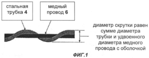
[22] фиг.1 изображает комбинированный скважинный кабель, включающий металлическую трубку, которой предварительно не придана форма, с обвитым вокруг нее медным проводом и слоем изоляции, расположенным вокруг медного провода;[22] figure 1 depicts a combined borehole cable comprising a metal tube, which is not pre-shaped, with a copper wire wrapped around it and a layer of insulation located around the copper wire;
[23] фиг.2 изображает поперечное сечение скважинного кабеля согласно первому варианту осуществления настоящего изобретения;[23] FIG. 2 is a cross-sectional view of a downhole cable according to a first embodiment of the present invention;
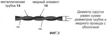
[24] фиг 3. изображает вид сбоку металлической трубки и медного элемента, скрученных в спиральных областях, образованных в металлической трубке согласно способу изготовления скважинных кабелей по первому варианту осуществления настоящего изобретения;[24] FIG. 3 is a side view of a metal tube and a copper element twisted in spiral regions formed in a metal tube according to the method for manufacturing the downhole cables of the first embodiment of the present invention;
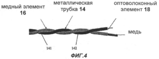
[25] фиг 4. изображает еще один вид сбоку металлической трубки и медного элемента, свитых вокруг одной оси во время процесса скручивания согласно способу изготовления скважинного кабеля по первому варианту осуществления настоящего изобретения;[25] FIG. 4 depicts yet another side view of a metal tube and a copper element twisted around one axis during a twisting process according to a method for manufacturing a downhole cable according to a first embodiment of the present invention;
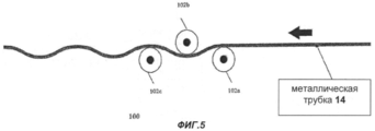
[26] фиг.5 изображает устройство для придания спиралевидной формы внешней периферической поверхности металлической трубки;[26] figure 5 depicts a device for imparting a spiral shape to the outer peripheral surface of a metal tube;
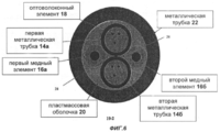
[27] фиг.6 изображает поперечное сечение двухтрубочного скважинного кабеля согласно второму варианту осуществления настоящего изобретения; и[27] FIG. 6 is a cross-sectional view of a two-pipe borehole cable according to a second embodiment of the present invention; and
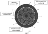
[28] фиг.7 изображает поперечное сечение многотрубочного скважинного кабеля согласно третьему варианту осуществления настоящего изобретения.[28] FIG. 7 is a cross-sectional view of a multi-tube well cable according to a third embodiment of the present invention.
ПОДРОБНОЕ ОПИСАНИЕ ВАРИАНТОВ ОСУЩЕСТВЛЕНИЯ ИЗОБРЕТЕНИЯDETAILED DESCRIPTION OF EMBODIMENTS OF THE INVENTION
[29] Далее приведено более подробное описание конкретных вариантов осуществления изобретения со ссылками на прилагаемые чертежи.[29] The following is a more detailed description of specific embodiments of the invention with reference to the accompanying drawings.
[30] В нижеприведенном описании для одинаковых элементов на всех чертежах использованы одинаковые номера позиций. Вопросы, рассмотренные в описании, такие как подробное описание конструкции и элементов, разобраны для облегчения всестороннего понимания изобретения. Очевидно, что настоящее изобретение можно осуществить без специального рассмотрения этих вопросов. Кроме того, не приведено подробного описания известных функций и конструкций, так как излишние детали могут затруднить понимание изобретения.[30] In the description below, the same reference numbers are used for the same elements throughout the drawings. The issues discussed in the description, such as a detailed description of the structure and elements, are disassembled to facilitate a comprehensive understanding of the invention. Obviously, the present invention can be carried out without special consideration of these issues. In addition, there is no detailed description of known functions and constructions, as excessive details may make it difficult to understand the invention.
[31] Скважинный кабель согласно одному из вариантов осуществления настоящего изобретения и способ изготовления указанного кабеля согласно такому варианту осуществления изобретения описаны со ссылками на фиг.2 и 3. На фиг.2 изображено поперечное сечение скважинного кабеля согласно первому варианту осуществления настоящего изобретения.[31] A downhole cable according to an embodiment of the present invention and a method for manufacturing said cable according to such an embodiment of the invention are described with reference to FIGS. 2 and 3. FIG. 2 shows a cross section of a downhole cable according to a first embodiment of the present invention.
[32] Скважинный кабель 10-1, который представлен на фиг.2, включает металлическую трубку 14, медный элемент 16, оболочку 20 и металлическую трубку 22. Как показано на фиг.2, в трубке 14 расположен оптоволоконный элемент 18. На фиг.3 представлены трубка 14, изображенная на фиг.2, внешней периферической поверхности которой придана спиралевидная форма (141, 142), и элемент 16, расположенный в спиралевидной области, образованной металлической трубкой.[32] The downhole cable 10-1, which is shown in FIG. 2, includes a
[33] В этом варианте осуществления изобретения трубка 14 представляет собой заполненную оптоволокном и гелем трубку из нержавеющей стали диаметром 0,079 дюйма. Однако трубку 14 можно изготовить из инколоя 825, инконеля 625 или любого другого металла.[33] In this embodiment, the
[34] Элемент 16 представляет собой медный провод диаметром 0,076 дюйма, который соответствует проводнику 18-го американского калибра проводов. Оболочка 20 может представлять собой пластмассовый профилированный кожух, который может быть размещен на наружной части трубки 14 и элемента 16. В этом варианте осуществления изобретения оболочка 20 имеет диаметр 0,169 дюйма, однако он может быть и другим.[34]
[35] Сердцевину, то есть трубку 14 и элемент 16, вставляют в трубку 22, которая может быть изготовлена из инколоя 825, нержавеющей стали 316 или любого другого пригодного металла. Толщину стенки трубки 22 можно изменять в соответствии с требованиями заказчика. Обычные значения толщины стенки составляют 0,028, 0,035 и 0,049 дюйма, однако настоящее изобретение не ограничено этими значениями. Диаметр трубки 22, которая изображена на фиг.1, составляет 1/4 дюйма. Сердцевина входит в металлическую трубку диаметром 1/4 дюйма с толщиной стенок 0,035 дюйма. Однако сердцевина не ограничена этими толщинами. Для специалиста очевидно, что настоящее изобретение можно использовать с другими толщинами стенок. В этом варианте осуществления изобретения скважинный кабель предназначен для стационарного оборудования.[35] The core, that is, the
[36] Далее со ссылками на фиг.2-5 описан пример способа изготовления скважинного кабеля, показанного на фиг.2. Покрытый оболочкой элемент 16 и трубку 14 размещают в известном кабелескруточном станке. Элемент 16 и трубка 14 расположены на подающих устройствах, которые регулируют натяжение каждого элемента для обеспечения согласованности процесса скручивания. Эти два элемента направляют с их подающих устройств к точке, где они сходятся. В этой точке, как показано на фиг.5, расположено устройство 100 для предварительного придания формы, через которое пропускают трубку 14. Устройство 100 используют для формирования постоянного спиралевидного изгиба элемента, так чтобы он сохранял эту форму в структуре кабеля. Наиболее часто используемое устройство 100 содержит последовательность из трех роликов 102а, 102b и 102с, через которые пропускают обрабатываемый элемент (трубку 14), и обеспечивает возможность регулировки расстояния между первым (102а) и третьим (102с) роликами, а второй ролик (102b) можно отрегулировать для создания смещения с целью получения требуемой кривизны обрабатываемого элемента, в данном случае трубки 14. Как показано на фиг.3 и 4, в процессе предварительного придания формы посредством роликов 102а, 102b и 102с спиралевидную форму 141, 142 придают внешней периферической поверхности трубки 14.[36] Next, with reference to FIGS. 2-5, an example of a method for manufacturing the downhole cable shown in FIG. 2 is described. The sheathed
[37] Эффективность последующего скручивания элемента 16 и трубки 14 вместе критически зависит от точности предварительного придания формы трубке 14. Для обеспечения равномерного скручивания элемента 16 и трубки 14, как показано на фиг.3, требуется высокая точность процесса предварительного придания формы. Типичное отклонение суммарного диаметра двух скрученных элементов составляет менее 0,004 дюйма. Указанная величина отклонения приведена в качестве примера и не является ограничительной, а настоящее изобретение не требует принятия указанного отклонения как жесткого требования к скрученным элементу 16 и трубке 14, вставляемым в трубку 22. Трубка 22 может допускать большую величину отклонения. Для обеспечения такого уровня отклонения контроль натяжения двух элементов должен быть крайне точным с возможностью независимого контроля двух элементов. В варианте осуществления изобретения, изображенного на фиг.3, предварительное придание формы трубке 14 и скручивание медного элемента в спирали, образованной трубкой 14, приводит к диаметру Dt' скрутки, равному сумме диаметра D14 трубки 14 и диаметра D16 элемента 16. То есть Dt'=D14+D16. Таким образом, согласно варианту осуществления настоящего изобретения диаметр Dt' уменьшен на величину диаметра D16 по сравнению с процессом скручивания медного элемента 6 и металлической трубки 4, не прошедшей процесс предварительного придания формы, как показано на фиг.1.[37] The efficiency of the subsequent twisting of the
[38] В частности, как показано на фиг.1, суммарный диаметр Dt скрутки, после того как провод 6 обвит вокруг трубки 4, которой предварительно не придана форма, равен сумме диаметра D4 трубки 4 и удвоенного диаметра D6 провода 6 с оболочкой. То есть Dt=D4+2×D6. Таким образом, если трубке 4 предварительно не придана форма, сердцевину приходится вставлять во внешнюю металлическую трубку больших размеров, что повышает производственные затраты.[38] In particular, as shown in FIG. 1, the total twist diameter Dt, after the wire 6 is wound around the tube 4, which has not been previously shaped, is equal to the sum of the diameter D4 of the tube 4 and the doubled diameter D6 of the wire 6 with the sheath. That is, Dt = D4 + 2 × D6. Thus, if the tube 4 is not pre-shaped, the core must be inserted into the outer metal tube of large sizes, which increases production costs.
[39] Изменение натяжения понижает качество спиралевидной формы 141 и 142 трубки 14, что приводит к изменению суммарного диаметра. Это является критичным из-за необходимости вставлять скрученные элемент 16 и трубку 14 в трубку 22 с обеспечением их перемещения в ней при приложении минимального усилия. Если спиралевидная форма 141 и 142 металлической трубки не образована должным образом, то есть трубке 14 предварительно придана форма с избыточным диаметром (диаметр спирали слишком велик) или ей предварительно придана форма с недостаточным диаметром, что приводит по существу к прямой стальной трубке с обвитым вокруг нее медным проводом, то потребуется усилие для установки двух этих элементов на место в трубку 22. Это приводит к нежелательному сжатию и деформации элемента 16 и трубки 14, что может ухудшить рабочие характеристики элемента 16 и оптоволокна 18, расположенного в трубке 14.[39] Changing the tension reduces the quality of the
[40] В этом варианте осуществления для достижения одинаковой деформации элементов натяжение каждого элемента (элемента 16 и трубки 14) поддерживали различным. Это делали потому, что на этапе постобработки, когда элемент 16 и металлическую трубку 14 оставляют в недеформированном или ненатяженном состоянии, деформации обоих элементов уменьшают на одинаковую величину, чтобы полученная длина элементов была одинакова. Если этого не выполнить, элемент с меньшей деформацией, чем у другого элемента, будет изгибаться, чтобы скомпенсировать полученное сжатие, обусловленное другим элементов с большей деформацией. Это может привести к трудностям при обработке во время добавления оболочки 20 к двум этим элементам и вставки этих двух элементов в трубку 22. Если деформация элемента 16 или трубки 14 меньше, чем у элемента с большей деформацией, возможен изгиб и различные повреждения элемента с меньшей деформацией. Это может, например, привести к блокированию кабеля на эксплутационном оборудовании или его сворачиванию, в особенности если он содержит медный провод.[40] In this embodiment, to achieve the same deformation of the elements, the tension of each element (
[41] После предварительного придания формы трубку 14 направляют к так называемой точке соединения, куда также направляют медный элемент. Так как элемент 16 обладает значительно меньшей жесткостью, чем трубка 14, он будет согласовываться с формой спирали трубки из нержавеющей стали, как показано на фиг.4. Другими словами, трубку 14 и элемент 16 концентрически свивают вокруг одной оси, как показано на фиг.4. После этой точки оба элемента, которые теперь скручены вместе, направляют к наматывателю станка.[41] After preliminary shaping, the
[42] В этом варианте осуществления элемент 16 и трубка 14 имеют диаметр примерно 0,078 дюйма. После скручивания двух этих элементов вместе на них устанавливают пластмассовый профилированный кожух 20 для удержания их вместе. В этом варианте осуществления такой кожух не требуется, но он может быть использован при необходимости. Диаметр с учетом профиля составляет примерно 0,171 дюйма. Эту конструкцию затем вставляют, например, в трубку 22 диаметром 1/4 дюйма с толщиной стенок 0,035 дюйма, так что полученный внутренний диаметр этой трубки составляет 0,180 дюйма. Конструктивные размеры некритичны и могут быть отрегулированы в соответствии с размерами других элементов, то есть размерами различных элемента 16 и заполненной оптоволокном трубки 14, а диаметр и толщина стенок внешней трубки 22 не обязательно должны составлять 1/4 и 0,035 дюйма соответственно.[42] In this embodiment,
[43] Далее описаны двухтрубчатый скважинный кабель согласно второму варианту осуществления настоящего изобретения и способ изготовления этого кабеля со ссылками на фиг.6.[43] The following describes a two-tube downhole cable according to a second embodiment of the present invention and a method for manufacturing this cable with reference to FIG. 6.
[44] На фиг.6 изображено поперечное сечение двухтрубчатого скважинного кабеля 10-2 согласно второму варианту осуществления настоящего изобретения.[44] FIG. 6 is a cross-sectional view of a two-tubular downhole cable 10-2 according to a second embodiment of the present invention.
[45] Как показано на фиг.6, кабель 10-2 включает первую металлическую трубку 14а и вторую металлическую трубку 14b, в каждой из которых расположен элемент 18. Кабель 10-2 дополнительно включает первый медный элемент 16а и второй медный элемент 16b.[45] As shown in FIG. 6, cable 10-2 includes a first metal tube 14a and a second metal tube 14b, each of which has an element 18. Cable 10-2 further includes a first copper element 16a and a second copper element 16b.
[46] Как показано на фиг.6, трубка 14b расположена параллельно трубке 14а. Первая периферическая поверхность трубки 14а соприкасается со второй периферической поверхностью трубки 14b. Первый и второй медные элементы 16а и 16b расположены в промежуточных областях 24 трубок 14а и 14b.[46] As shown in FIG. 6, the tube 14b is parallel to the tube 14a. The first peripheral surface of the tube 14a is in contact with the second peripheral surface of the tube 14b. The first and second copper elements 16a and 16b are located in the
[47] Трубки 14а и 14b и элементы 16а и 16b помещают в оболочку 20. Эту комбинацию затем можно вставить в трубку 22 аналогично скважинному кабелю, изображенному на фиг.2.[47] The tubes 14a and 14b and the elements 16a and 16b are placed in the sheath 20. This combination can then be inserted into the tube 22 similarly to the downhole cable shown in FIG. 2.
[48] Характеристики трубок 14а и 14b, элементов 16а и16b, оболочки 20 и трубки 22 можно изменять, как описано выше применительно к фиг.2. Например, в этом варианте осуществления элемент 16 может представлять собой проводник 21-го американского калибра проводов. Диаметр трубок 14а и 14b может составлять 0,046 дюйма, однако он не ограничен этим значением.[48] The characteristics of the tubes 14a and 14b, the elements 16a and 16b, the sheath 20 and the tube 22 can be changed, as described above in relation to figure 2. For example, in this embodiment,
[49] Для изготовления двухтрубчатого кабеля 10-2, который изображен на фиг.6, трубки 14а и 14b и элементы 16а и 16b скручивают вместе одновременно. Все элементы 14а, 14b, 16а и 16с размещают в кабелескруточном станке. Устройства кабелескруточного станка обеспечивают контроль требуемого положения обрабатываемых элементов в точке соединения этих элементов. Когда трубки 14а и 14b и элементы 16а и 16b размещены в требуемом положении, то есть когда трубки 14а и 14b соприкасаются друг с другом, а элементы 16а и 16b расположены в промежуточных областях трубок 14а и 14b, их скручивают вместе для образования сердцевины. Такой способ скручивания называют способом скручивания сигарного типа, и в соответствии с ним отдельные элементы скручивают таким образом, что их не завивают вокруг своей оси, а свивают с другими элементами.[49] For the manufacture of the two-tube cable 10-2, which is shown in FIG. 6, the tubes 14a and 14b and the elements 16a and 16b are twisted together at the same time. All elements 14a, 14b, 16a and 16c are placed in a cable winder. Cable winding machine devices provide control of the required position of the processed elements at the junction of these elements. When the tubes 14a and 14b and the elements 16a and 16b are placed in the desired position, that is, when the tubes 14a and 14b are in contact with each other, and the elements 16a and 16b are located in the intermediate regions of the tubes 14a and 14b, they are twisted together to form a core. This method of twisting is called the method of twisting a cigar type, and in accordance with it, the individual elements are twisted so that they do not curl around its axis, but are twisted with other elements.
[50] В отличие от кабеля 10-1 в соответствии с первым вариантом осуществления, изображенным на фиг.2, в случае кабеля 10-2 в соответствии с этим вариантом осуществления трубки 14а и 14b не требуется подвергать процессу предварительного придания формы, проиллюстрированному на фиг.5.[50] Unlike the cable 10-1 in accordance with the first embodiment shown in FIG. 2, in the case of the cable 10-2 in accordance with this embodiment, the tubes 14a and 14b do not need to be subjected to the pre-molding process illustrated in FIG. .5.
Предварительное придание формы трубкам 14а и 14b можно выполнять при необходимости. Предварительное придание формы трубкам 14а и 14b не требуется, если они имеют одинаковые характеристики. Когда элементы 14а, 14b, 16а и 16с скручены в спиралевидную форму, они свиты вокруг общей оси, что приводит к равномерному свиванию. Таким образом, в данном случае диаметры элементов 16а и 16b не вносят вклад в суммарный диаметр скрученных элементов 14а, 14b, 16a и 16b, так как при скручивании их располагают в спиралевидных промежуточных областях трубок 14а и 14b.Pre-shaping the tubes 14a and 14b can be performed if necessary. Pre-shaping the tubes 14a and 14b is not required if they have the same characteristics. When the elements 14a, 14b, 16a and 16c are twisted into a spiral shape, they are twisted around a common axis, which leads to uniform twisting. Thus, in this case, the diameters of the elements 16a and 16b do not contribute to the total diameter of the twisted elements 14a, 14b, 16a and 16b, since when twisted they are placed in the spiral-shaped intermediate regions of the tubes 14a and 14b.
[51] Далее описан третий вариант осуществления настоящего изобретения со ссылкой на фиг.7.[51] Next, a third embodiment of the present invention is described with reference to FIG.
[52] На фиг.7 изображен многотрубочный скважинный кабель 10-3, включающий медный, элемент 16' и металлические трубки 14', которые скручены с элементом 16'. На скрученные элементы 16' и 14' можно наложить оболочку 20 для их содержания с образованием сердцевины. После этого сердцевину можно вставить в трубку 22.[52] Figure 7 shows a multi-tube downhole cable 10-3, including copper, element 16 'and metal tubes 14', which are twisted with element 16 '. On the twisted elements 16 'and 14' can be applied to the shell 20 for their content with the formation of the core. After that, the core can be inserted into the tube 22.
[53] Вышеприведенные варианты осуществления изобретения приведены только для примера и не ограничивают настоящего изобретения. Идея изобретения может быть легко применена к другим типам устройств. Кроме того, описание вариантов осуществления настоящего изобретения является иллюстративным и не ограничивает объем изобретения, определяемый формулой изобретения. При этом для специалистов очевидны различные альтернативы, модификации и изменения настоящего изобретения.[53] The foregoing embodiments of the invention are by way of example only and do not limit the present invention. The idea of the invention can be easily applied to other types of devices. In addition, the description of embodiments of the present invention is illustrative and does not limit the scope of the invention defined by the claims. At the same time, various alternatives, modifications and changes of the present invention are obvious to specialists.
Claims (12)
- придание спиралевидной формы внешней периферической поверхности металлической трубки, в которой расположен оптоволоконный элемент; и скручивание медного элемента в спиралевидной области, образованной металлической трубкой.1. A method of manufacturing a cable, including:
- giving a spiral shape to the outer peripheral surface of the metal tube in which the fiber optic element is located; and twisting the copper element in a spiral region formed by a metal tube.
- металлическую трубку, которая имеет внешнюю периферическую поверхность спиралевидной формы и в которой расположен оптоволоконный элемент;
- медный элемент, скрученный в спиралевидной области, образованной металлической трубкой.3. A cable comprising:
- a metal tube, which has an external peripheral surface of a spiral shape and in which a fiber optic element is located;
- a copper element twisted in a spiral region formed by a metal tube.
- размещение в кабелескруточном станке первой и второй металлической трубок параллельно друг другу таким образом, чтобы периферическая поверхность первой трубки соприкасалась с периферической поверхностью второй трубки;
- размещение в промежуточных областях первой и второй трубок первого и второго медных элементов;
- скручивание вместе первой и второй трубок и первого и второго медных элементов путем приведения в действие кабелескруточного станка.5. A method of manufacturing a cable, including:
- placing the first and second metal tubes in the cable winder parallel to each other so that the peripheral surface of the first tube is in contact with the peripheral surface of the second tube;
- placement in the intermediate areas of the first and second tubes of the first and second copper elements;
- twisting together the first and second tubes and the first and second copper elements by actuating the cable winding machine.
- перед размещением первой и второй трубок придание первой спиралевидной формы периферической поверхности первой трубки; и
- придание второй спиралевидной формы периферической поверхности второй трубки;
- причем скручивание дополнительно включает скручивание первого медного элемента в первой спиралевидной промежуточной области первой спиралевидной формы периферической поверхности первой трубки и в первой спиралевидной промежуточной области второй спиралевидной формы периферической поверхности второй трубки и скручивание второго медного элемента во второй спиралевидной промежуточной области первой спиралевидной формы периферической поверхности первой трубки и во второй спиралевидной промежуточной области второй спиралевидной формы периферической поверхности второй трубки.7. The method according to claim 5, further comprising:
- before placing the first and second tubes, giving the first spiral shape to the peripheral surface of the first tube; and
- giving the second spiral shape to the peripheral surface of the second tube;
and wherein twisting further includes twisting the first copper element in the first spiral-shaped intermediate region of the first spiral-shaped peripheral surface of the first tube and in the first spiral-shaped intermediate region of the second spiral-shaped peripheral surface of the second tube and twisting the second copper element in the second spiral-shaped intermediate region of the first spiral-shaped peripheral surface of the first tube and in the second helical intermediate region of the second helical shaped peripheral surface of the second tube.
- размещение пластмассового профилированного кожуха на наружной части скрученных первой и второй трубок и первого и второго медных элементов.8. The method according to claim 5, further comprising:
- placement of a plastic profiled casing on the outer part of the twisted first and second tubes and the first and second copper elements.
- первую металлическую трубку;
- вторую металлическую трубку, расположенную параллельно первой трубке таким образом, что периферическая поверхность первой трубки соприкасается с периферической поверхностью второй трубки;
- первый и второй медные элементы, расположенные в промежуточных областях первой и второй трубок.9. Two-pipe downhole cable containing:
- the first metal tube;
- a second metal tube parallel to the first tube so that the peripheral surface of the first tube is in contact with the peripheral surface of the second tube;
- the first and second copper elements located in the intermediate areas of the first and second tubes.
- медный элемент;
- металлические трубки, которые скручены вокруг медного элемента и в каждой из которых расположен оптоволоконный элемент;
- профилированный кожух, покрывающий наружную часть медного элемента и металлических трубок с образованием сердцевины
- металлическую трубку, в которую вставлена указанная сердцевина.10. Multitubular borehole cable containing:
- copper element;
- metal tubes that are twisted around a copper element and in each of which a fiber optic element is located;
- profiled casing covering the outer part of the copper element and metal tubes with the formation of the core
- a metal tube into which said core is inserted.
Applications Claiming Priority (2)
| Application Number | Priority Date | Filing Date | Title |
|---|---|---|---|
| US82395906P | 2006-08-30 | 2006-08-30 | |
| US60/823,959 | 2006-08-30 |
Publications (2)
| Publication Number | Publication Date |
|---|---|
| RU2008146784A RU2008146784A (en) | 2010-06-10 |
| RU2445656C2 true RU2445656C2 (en) | 2012-03-20 |
Family
ID=39136543
Family Applications (1)
| Application Number | Title | Priority Date | Filing Date |
|---|---|---|---|
| RU2008146784/28A RU2445656C2 (en) | 2006-08-30 | 2007-08-29 | Borehole cables with fibre-optic and copper elements |
Country Status (11)
| Country | Link |
|---|---|
| US (7) | US8295665B2 (en) |
| EP (3) | EP2057638B1 (en) |
| AU (1) | AU2007290525B2 (en) |
| BR (1) | BRPI0707034A2 (en) |
| CA (1) | CA2656843C (en) |
| CO (1) | CO6140080A2 (en) |
| ES (1) | ES2565239T3 (en) |
| MX (1) | MX2008015518A (en) |
| MY (1) | MY157280A (en) |
| RU (1) | RU2445656C2 (en) |
| WO (1) | WO2008027387A2 (en) |
Cited By (4)
| Publication number | Priority date | Publication date | Assignee | Title |
|---|---|---|---|---|
| RU2624770C2 (en) * | 2015-12-29 | 2017-07-06 | Федеральное государственное бюджетное образовательное учреждение высшего образования "Поволжский государственный университет телекоммуникаций и информатики" (ФГБОУ ВО ПГУТИ) | Method of leveling mode connection in optical fibers on building length of optical cable of modular construction with multimode or small-mode optical fibers |
| RU2723291C2 (en) * | 2015-12-28 | 2020-06-09 | Призмиан С.П.А. | Downhole cable with reduced diameter |
| RU2748368C1 (en) * | 2017-12-04 | 2021-05-24 | Призмиан С.П.А. | Electrical cable for vertical applications |
| RU2792289C1 (en) * | 2021-05-10 | 2023-03-21 | Шиньда (Таншань) Криэйтив Ойл Энд Гэз Эквипмент Ко., Лтд. | Sheathed tubular cable with colored identification tape and method for its manufacture |
Families Citing this family (52)
| Publication number | Priority date | Publication date | Assignee | Title |
|---|---|---|---|---|
| MY157280A (en) | 2006-08-30 | 2016-05-31 | Afl Telecommunications Llc | Downhole cables with both fiber and copper elements |
| US9080425B2 (en) | 2008-10-17 | 2015-07-14 | Foro Energy, Inc. | High power laser photo-conversion assemblies, apparatuses and methods of use |
| WO2010096086A1 (en) | 2008-08-20 | 2010-08-26 | Foro Energy Inc. | Method and system for advancement of a borehole using a high power laser |
| US9562395B2 (en) | 2008-08-20 | 2017-02-07 | Foro Energy, Inc. | High power laser-mechanical drilling bit and methods of use |
| US9242309B2 (en) | 2012-03-01 | 2016-01-26 | Foro Energy Inc. | Total internal reflection laser tools and methods |
| US10301912B2 (en) * | 2008-08-20 | 2019-05-28 | Foro Energy, Inc. | High power laser flow assurance systems, tools and methods |
| US9347271B2 (en) | 2008-10-17 | 2016-05-24 | Foro Energy, Inc. | Optical fiber cable for transmission of high power laser energy over great distances |
| US9664012B2 (en) | 2008-08-20 | 2017-05-30 | Foro Energy, Inc. | High power laser decomissioning of multistring and damaged wells |
| US8571368B2 (en) | 2010-07-21 | 2013-10-29 | Foro Energy, Inc. | Optical fiber configurations for transmission of laser energy over great distances |
| US9027668B2 (en) | 2008-08-20 | 2015-05-12 | Foro Energy, Inc. | Control system for high power laser drilling workover and completion unit |
| US9719302B2 (en) | 2008-08-20 | 2017-08-01 | Foro Energy, Inc. | High power laser perforating and laser fracturing tools and methods of use |
| US8627901B1 (en) | 2009-10-01 | 2014-01-14 | Foro Energy, Inc. | Laser bottom hole assembly |
| US9089928B2 (en) | 2008-08-20 | 2015-07-28 | Foro Energy, Inc. | Laser systems and methods for the removal of structures |
| US9244235B2 (en) | 2008-10-17 | 2016-01-26 | Foro Energy, Inc. | Systems and assemblies for transferring high power laser energy through a rotating junction |
| US9669492B2 (en) | 2008-08-20 | 2017-06-06 | Foro Energy, Inc. | High power laser offshore decommissioning tool, system and methods of use |
| US9267330B2 (en) | 2008-08-20 | 2016-02-23 | Foro Energy, Inc. | Long distance high power optical laser fiber break detection and continuity monitoring systems and methods |
| US9138786B2 (en) | 2008-10-17 | 2015-09-22 | Foro Energy, Inc. | High power laser pipeline tool and methods of use |
| US9360631B2 (en) | 2008-08-20 | 2016-06-07 | Foro Energy, Inc. | Optics assembly for high power laser tools |
| RU2012130531A (en) | 2010-01-27 | 2014-03-10 | Афл Телекомьюникэйшнс Ллс | CABLE CABLE |
| US8885999B2 (en) | 2010-03-19 | 2014-11-11 | Corning Cable Systems Llc | Optical USB cable with controlled fiber positioning |
| WO2012024285A1 (en) | 2010-08-17 | 2012-02-23 | Foro Energy Inc. | Systems and conveyance structures for high power long distance laster transmission |
| WO2012116155A1 (en) | 2011-02-24 | 2012-08-30 | Foro Energy, Inc. | Electric motor for laser-mechanical drilling |
| WO2012167102A1 (en) | 2011-06-03 | 2012-12-06 | Foro Energy Inc. | Rugged passively cooled high power laser fiber optic connectors and methods of use |
| CN103620466B (en) | 2011-06-10 | 2017-04-26 | 康宁光缆系统有限责任公司 | Fiber optic cables allowing fiber translation to reduce bend attenuation |
| RU2627061C2 (en) * | 2011-09-09 | 2017-08-03 | Конинклейке Филипс Н.В. | Optical monitoring device for monitoring the value of the curvature of a flexible medical instrument |
| WO2013066315A1 (en) * | 2011-11-01 | 2013-05-10 | Empire Technology Development Llc | Cable with optical fiber for prestressed concrete |
| US8676012B2 (en) | 2012-01-20 | 2014-03-18 | Corning Cable Systems Llc | Fiber optic cable for very-short-distance networks |
| US9523832B2 (en) * | 2012-03-23 | 2016-12-20 | Afl Telecommunications Llc | High temperature, zero fiber strain, fiber optic cable |
| US9859038B2 (en) | 2012-08-10 | 2018-01-02 | General Cable Technologies Corporation | Surface modified overhead conductor |
| US9170389B2 (en) | 2012-08-28 | 2015-10-27 | Corning Cable Systems Llc | Hybrid fiber optic cable systems |
| JP2014078435A (en) * | 2012-10-11 | 2014-05-01 | Sumitomo Electric Ind Ltd | Opto-electric composite cable |
| US10957468B2 (en) | 2013-02-26 | 2021-03-23 | General Cable Technologies Corporation | Coated overhead conductors and methods |
| US9091154B2 (en) * | 2013-03-28 | 2015-07-28 | Schlumberger Technology Corporation | Systems and methods for hybrid cable telemetry |
| GB2528819B (en) * | 2013-07-23 | 2020-04-01 | Halliburton Energy Services Inc | Managing strain on a downhole cable |
| US11268329B2 (en) | 2013-09-13 | 2022-03-08 | Schlumberger Technology Corporation | Electrically conductive fiber optic slickline for coiled tubing operations |
| US9136045B2 (en) | 2013-10-30 | 2015-09-15 | General Cable Technologies Corporation | Composite communications cable |
| GB2527580B (en) * | 2014-06-26 | 2021-07-21 | British Telecomm | Installation of cable connections |
| BR112018001195B1 (en) | 2015-07-21 | 2022-08-09 | General Cable Technologies Corp | ELECTRICAL ACCESSORIES FOR POWER TRANSMISSION SYSTEMS AND METHODS FOR PREPARING SUCH ELECTRICAL ACCESSORIES |
| US10221687B2 (en) | 2015-11-26 | 2019-03-05 | Merger Mines Corporation | Method of mining using a laser |
| EP3693779B1 (en) * | 2016-06-01 | 2022-05-04 | Panasonic Intellectual Property Management Co., Ltd. | Cable assembly |
| WO2017210544A1 (en) * | 2016-06-03 | 2017-12-07 | Afl Telecommunications Llc | Downhole logging cables with central conductors |
| CA2961629A1 (en) | 2017-03-22 | 2018-09-22 | Infocus Energy Services Inc. | Reaming systems, devices, assemblies, and related methods of use |
| US10892822B2 (en) | 2017-02-01 | 2021-01-12 | British Telecommunications Public Limited Company | Optical fiber event location |
| US10307138B2 (en) | 2017-04-06 | 2019-06-04 | United Technologies Corporation | Wave guide with electric power conduit |
| US20180350488A1 (en) * | 2017-06-02 | 2018-12-06 | Schlumberger Technology Corporation | Electrical cables and processes for making and using same |
| CN107240459A (en) * | 2017-07-12 | 2017-10-10 | 中天电力光缆有限公司 | A kind of optoelectronic composite cable and its manufacture method |
| WO2019016263A1 (en) | 2017-07-20 | 2019-01-24 | British Telecommunications Public Limited Company | Optical fibre |
| KR102604855B1 (en) * | 2018-07-23 | 2023-11-21 | 엘에스전선 주식회사 | Optical And Power Composite Cable And Optical And Power Composite Jumper Cord |
| US10613287B1 (en) * | 2018-11-20 | 2020-04-07 | Afl Telecommunications Llc | Methods for forming fiber optic cables and fiber optic cables having helical buffer tubes |
| CN111485830A (en) * | 2020-05-12 | 2020-08-04 | 信达科创(唐山)石油设备有限公司 | Packaging pipe cable with identification mark and preparation method thereof |
| PL4024106T3 (en) * | 2020-12-31 | 2024-08-05 | Prysmian S.P.A. | Multisensing optical fiber cable |
| AT526701A1 (en) * | 2022-11-14 | 2024-05-15 | Nbg Holding Gmbh | Borehole cable with a protective sheath |
Citations (3)
| Publication number | Priority date | Publication date | Assignee | Title |
|---|---|---|---|---|
| US4575184A (en) * | 1983-06-06 | 1986-03-11 | Sumitomo Electric Industries, Ltd. | Flame retardant optical composite cable |
| US5493626A (en) * | 1993-05-21 | 1996-02-20 | Westech Geophysical, Inc. | Reduced diameter down-hole instrument electrical/optical fiber cable |
| JP2001311859A (en) * | 2000-04-28 | 2001-11-09 | Sumitomo Electric Ind Ltd | Self-supporting cable and its aerial wire extending method |
Family Cites Families (71)
| Publication number | Priority date | Publication date | Assignee | Title |
|---|---|---|---|---|
| US2147095A (en) * | 1935-01-17 | 1939-02-14 | Hochstadter Martin | Multiconductor cable |
| US2318601A (en) * | 1939-06-22 | 1943-05-11 | Doble Eng | Electrical means for indicating temperature conditions |
| US2348752A (en) * | 1940-09-17 | 1944-05-16 | Int Standard Electric Corp | Electric cable |
| US3007300A (en) * | 1946-09-20 | 1961-11-07 | Preformed Line Products Co | Helically-preformed wire envelope and methods of use |
| US2761273A (en) * | 1955-12-02 | 1956-09-04 | Preformed Line Products Co | Dead end for cables |
| US3035086A (en) | 1959-03-23 | 1962-05-15 | Union Carbide Corp | Process for producing acrylic acid esters |
| US3257863A (en) * | 1963-08-12 | 1966-06-28 | Teleflex Inc | Cable construction |
| US3257883A (en) | 1963-10-14 | 1966-06-28 | American Mach & Foundry | Apparatus for making cigarettes |
| US3660590A (en) * | 1970-11-23 | 1972-05-02 | James E Conant | Electro-optical fluidic transfer conduit |
| US3750058A (en) * | 1971-12-08 | 1973-07-31 | Bell Telephone Labor Inc | Waveguide structure utilizing compliant helical support |
| US4146302A (en) * | 1975-06-02 | 1979-03-27 | General Cable Corporation | Construction of cable made of optical fibres |
| FR2318975A1 (en) * | 1975-07-23 | 1977-02-18 | Sodetal | MACHINE FOR THE MANUFACTURING OF CABLES |
| US4226504A (en) * | 1976-03-15 | 1980-10-07 | Akzona Incorporated | Protection of optical fibers |
| US4205888A (en) * | 1978-05-12 | 1980-06-03 | Wade Jack W | Ground connector for interlocked armor electrical cable |
| FR2460492A1 (en) * | 1979-06-28 | 1981-01-23 | Cables De Lyon Geoffroy Delore | FIBER OPTIC UNDERWATER CABLE |
| US4534618A (en) * | 1982-04-21 | 1985-08-13 | U.S. Philips Corporation | Optical communication cable |
| DE3243915A1 (en) * | 1982-11-25 | 1984-05-30 | Siemens AG, 1000 Berlin und 8000 München | TUBE STORAGE SZ SEWING MACHINE |
| GB8406635D0 (en) * | 1984-03-14 | 1984-04-18 | Bicc Plc | Optical fibre element |
| US4687294A (en) * | 1984-05-25 | 1987-08-18 | Cooper Industries, Inc. | Fiber optic plenum cable |
| US4723831A (en) * | 1985-12-02 | 1988-02-09 | American Telephone And Telegraph Company At&T Bell Laboratories | Optical fiber communications cable |
| CH671639A5 (en) * | 1986-10-24 | 1989-09-15 | Bbc Brown Boveri & Cie | |
| US4852964A (en) * | 1987-03-04 | 1989-08-01 | Storm Products Co. | Fiber optic coil cord |
| FR2636743B1 (en) * | 1988-09-20 | 1993-01-08 | Sat Cie | OPTICAL FIBER CABLE |
| JPH02244013A (en) | 1989-03-17 | 1990-09-28 | Fujikura Ltd | Optical fiber cable |
| GB2240638B (en) | 1990-02-02 | 1993-09-22 | Telephone Cables Ltd | Optical fibre cable having an optical fibre in a welded metal tube |
| CA2090053C (en) * | 1992-03-24 | 1997-10-28 | Lawrence Russell Dunn | Hybrid communications cable for enhancement of transmission capability |
| US5247599A (en) * | 1992-06-05 | 1993-09-21 | Sumitomo Electric Fiber Optics Corp. | Steam resistant optical fiber cable |
| US5222178A (en) * | 1992-07-17 | 1993-06-22 | Hughes Aircraft Company | High density fiber optic cable packaging |
| US5318215A (en) * | 1993-02-23 | 1994-06-07 | Hitachi Cable Ltd. | Method of forming cladded cable having fiber with excess length enclosed therein |
| US5606151A (en) * | 1993-03-17 | 1997-02-25 | Belden Wire & Cable Company | Twisted parallel cable |
| US5666452A (en) * | 1994-05-20 | 1997-09-09 | Belden Wire & Cable Company | Shielding tape for plenum rated cables |
| US5956445A (en) * | 1994-05-20 | 1999-09-21 | Belden Wire & Cable Company | Plenum rated cables and shielding tape |
| DE4425464A1 (en) * | 1994-07-19 | 1996-01-25 | Rheydt Kabelwerk Ag | Self-supporting electrical air cable |
| SE513714C2 (en) | 1995-02-23 | 2000-10-30 | Alcatel Iko Kabel Ab | Device for SZ cabling of multi-party cables |
| DE29520915U1 (en) * | 1995-03-04 | 1996-05-02 | Alcatel Kabel AG & Co., 30179 Hannover | Communication cable |
| US5495547A (en) * | 1995-04-12 | 1996-02-27 | Western Atlas International, Inc. | Combination fiber-optic/electrical conductor well logging cable |
| GB2303938A (en) * | 1995-07-31 | 1997-03-05 | Stc Submarine Systems Ltd | Optical fibre cable having kingwire bearing extruded thermoplastic elastomer layers |
| US5767441A (en) * | 1996-01-04 | 1998-06-16 | General Cable Industries | Paired electrical cable having improved transmission properties and method for making same |
| GB9616400D0 (en) * | 1996-08-03 | 1996-09-11 | Limited | Electrical and optical cable |
| US20020033132A1 (en) * | 1996-08-27 | 2002-03-21 | Kim Roland Y. | Crush-resistant polymeric microcellular wire coating |
| US6219482B1 (en) * | 1997-04-15 | 2001-04-17 | Helios Inc. | Metallic tubes for housing optical fibers and process for producing the same |
| US20020001441A1 (en) * | 1999-04-13 | 2002-01-03 | Francisco J. Avellanet | Hybrid cable having both an optical fiber and a multifilament twisted and drawn element |
| DE19813444A1 (en) * | 1998-03-26 | 1999-09-30 | Cit Alcatel | Hybrid cable with optical fiber and electrical conductor |
| US6396414B1 (en) * | 1998-11-23 | 2002-05-28 | Schlumberger Technology Corporation | Retractable electrical/optical connector |
| US6249629B1 (en) * | 1998-12-10 | 2001-06-19 | Siecor Operations, Llc | Robust fiber optic cables |
| NO313607B1 (en) * | 1999-05-19 | 2002-10-28 | Cit Alcatel | Optical underwater cable |
| PL196683B1 (en) * | 1999-06-18 | 2008-01-31 | Belden Wire & Cable Co | High performance data cable |
| DE10006806A1 (en) * | 2000-02-15 | 2001-08-16 | Alcatel Sa | Metallic optical aerial cable |
| ATE313093T1 (en) * | 2000-05-16 | 2005-12-15 | Nexans | OPTICAL CABLE |
| JP3589348B2 (en) * | 2000-10-05 | 2004-11-17 | 古河電気工業株式会社 | Electric / optical composite cable |
| US6466719B2 (en) * | 2001-01-04 | 2002-10-15 | The United States Of America As Represented By The Secretary Of The Navy | Optical temperature sensing arrangement for towed cable |
| US6563107B2 (en) * | 2001-01-11 | 2003-05-13 | Canadian Space Agency | Topological and motion measuring tool |
| US6881194B2 (en) * | 2001-03-21 | 2005-04-19 | Asahi Intec Co., Ltd. | Wire-stranded medical hollow tube, and a medical guide wire |
| DK1446690T3 (en) * | 2001-11-19 | 2008-03-03 | Prysmian Cables & Systems Ltd | Fiber optic drop cables |
| US6848541B2 (en) * | 2002-07-11 | 2005-02-01 | Nkf Kabel B.V. | Optical cable installation with cable lubricator |
| KR100511116B1 (en) * | 2003-02-14 | 2005-08-30 | 엘에스전선 주식회사 | Loose tube optical cable having straight aggregation structure |
| KR100492957B1 (en) * | 2003-02-25 | 2005-06-02 | 엘에스전선 주식회사 | Loose Tube Optical Cable |
| KR100642382B1 (en) * | 2003-02-26 | 2006-11-03 | 엘에스전선 주식회사 | Optical Cable Having Waved Metal Tube and Method and Apparatus for Producing the Same |
| JP2005137747A (en) | 2003-11-10 | 2005-06-02 | Toshiba Corp | Ultrasonic diagnostic system |
| US7324730B2 (en) * | 2004-05-19 | 2008-01-29 | Schlumberger Technology Corporation | Optical fiber cables for wellbore applications |
| US7321709B2 (en) * | 2004-11-11 | 2008-01-22 | Sumitomo Electric Industries, Ltd. | Optical cable |
| US7221831B2 (en) * | 2005-03-03 | 2007-05-22 | Nexans | Multi-tube fiber optic cable and system and method for making the same |
| US7269324B2 (en) * | 2005-03-31 | 2007-09-11 | Crownover John D | Helical fiber optic mode scrambler |
| ATE425473T1 (en) * | 2005-08-31 | 2009-03-15 | Nexans | COMPOSITE CABLE |
| MY157280A (en) * | 2006-08-30 | 2016-05-31 | Afl Telecommunications Llc | Downhole cables with both fiber and copper elements |
| US7763802B2 (en) * | 2006-09-13 | 2010-07-27 | Schlumberger Technology Corporation | Electrical cable |
| US7696437B2 (en) * | 2006-09-21 | 2010-04-13 | Belden Technologies, Inc. | Telecommunications cable |
| JP2011054410A (en) * | 2009-09-01 | 2011-03-17 | Yoshinokawa Electric Wire & Cable Co Ltd | High-frequency extrafine pair cable and method for manufacturing the same |
| RU2012130531A (en) * | 2010-01-27 | 2014-03-10 | Афл Телекомьюникэйшнс Ллс | CABLE CABLE |
| US20120080225A1 (en) * | 2010-09-30 | 2012-04-05 | Apple Inc. | Cable for electrical and optical transmission |
| US8929701B2 (en) * | 2012-02-15 | 2015-01-06 | Draka Comteq, B.V. | Loose-tube optical-fiber cable |
-
2007
- 2007-08-29 MY MYPI20083310A patent/MY157280A/en unknown
- 2007-08-29 EP EP07837447.7A patent/EP2057638B1/en active Active
- 2007-08-29 US US12/439,412 patent/US8295665B2/en active Active
- 2007-08-29 BR BRPI0707034-9A patent/BRPI0707034A2/en not_active Application Discontinuation
- 2007-08-29 CA CA2656843A patent/CA2656843C/en active Active
- 2007-08-29 WO PCT/US2007/018926 patent/WO2008027387A2/en active Application Filing
- 2007-08-29 AU AU2007290525A patent/AU2007290525B2/en active Active
- 2007-08-29 ES ES07837447.7T patent/ES2565239T3/en active Active
- 2007-08-29 RU RU2008146784/28A patent/RU2445656C2/en not_active IP Right Cessation
- 2007-08-29 EP EP16159259.7A patent/EP3051324A1/en not_active Withdrawn
- 2007-08-29 MX MX2008015518A patent/MX2008015518A/en active IP Right Grant
- 2007-08-29 EP EP20120157559 patent/EP2461197A1/en not_active Withdrawn
-
2008
- 2008-12-26 CO CO08137206A patent/CO6140080A2/en unknown
-
2012
- 2012-10-19 US US13/656,275 patent/US20130039625A1/en not_active Abandoned
-
2013
- 2013-06-14 US US13/918,426 patent/US9069148B2/en active Active
-
2015
- 2015-06-03 US US14/729,252 patent/US9589706B2/en active Active
-
2017
- 2017-01-18 US US15/408,914 patent/US9941031B2/en active Active
-
2018
- 2018-02-19 US US15/898,947 patent/US10297369B2/en active Active
-
2019
- 2019-05-15 US US16/412,974 patent/US10784023B2/en active Active
Patent Citations (3)
| Publication number | Priority date | Publication date | Assignee | Title |
|---|---|---|---|---|
| US4575184A (en) * | 1983-06-06 | 1986-03-11 | Sumitomo Electric Industries, Ltd. | Flame retardant optical composite cable |
| US5493626A (en) * | 1993-05-21 | 1996-02-20 | Westech Geophysical, Inc. | Reduced diameter down-hole instrument electrical/optical fiber cable |
| JP2001311859A (en) * | 2000-04-28 | 2001-11-09 | Sumitomo Electric Ind Ltd | Self-supporting cable and its aerial wire extending method |
Cited By (6)
| Publication number | Priority date | Publication date | Assignee | Title |
|---|---|---|---|---|
| RU2723291C2 (en) * | 2015-12-28 | 2020-06-09 | Призмиан С.П.А. | Downhole cable with reduced diameter |
| RU2624770C2 (en) * | 2015-12-29 | 2017-07-06 | Федеральное государственное бюджетное образовательное учреждение высшего образования "Поволжский государственный университет телекоммуникаций и информатики" (ФГБОУ ВО ПГУТИ) | Method of leveling mode connection in optical fibers on building length of optical cable of modular construction with multimode or small-mode optical fibers |
| RU2748368C1 (en) * | 2017-12-04 | 2021-05-24 | Призмиан С.П.А. | Electrical cable for vertical applications |
| US11450455B2 (en) | 2017-12-04 | 2022-09-20 | Prysmian S.P.A. | Electrical cable for vertical applications |
| RU2805143C2 (en) * | 2018-10-12 | 2023-10-11 | Веллтек A/С | System for well intervention and method of operating the system for well intervention |
| RU2792289C1 (en) * | 2021-05-10 | 2023-03-21 | Шиньда (Таншань) Криэйтив Ойл Энд Гэз Эквипмент Ко., Лтд. | Sheathed tubular cable with colored identification tape and method for its manufacture |
Also Published As
| Publication number | Publication date |
|---|---|
| US9589706B2 (en) | 2017-03-07 |
| ES2565239T3 (en) | 2016-04-01 |
| AU2007290525B2 (en) | 2013-08-15 |
| MX2008015518A (en) | 2008-12-18 |
| US20170125138A1 (en) | 2017-05-04 |
| WO2008027387A2 (en) | 2008-03-06 |
| CA2656843C (en) | 2016-10-18 |
| US10784023B2 (en) | 2020-09-22 |
| RU2008146784A (en) | 2010-06-10 |
| EP2057638B1 (en) | 2016-03-09 |
| CO6140080A2 (en) | 2010-03-19 |
| AU2007290525A1 (en) | 2008-03-06 |
| US8295665B2 (en) | 2012-10-23 |
| US20130039625A1 (en) | 2013-02-14 |
| US20190267159A1 (en) | 2019-08-29 |
| US20150270033A1 (en) | 2015-09-24 |
| EP2461197A1 (en) | 2012-06-06 |
| US9941031B2 (en) | 2018-04-10 |
| US9069148B2 (en) | 2015-06-30 |
| WO2008027387A3 (en) | 2008-08-07 |
| MY157280A (en) | 2016-05-31 |
| EP3051324A1 (en) | 2016-08-03 |
| US20180174711A1 (en) | 2018-06-21 |
| US20100008631A1 (en) | 2010-01-14 |
| US20130279864A1 (en) | 2013-10-24 |
| EP2057638A2 (en) | 2009-05-13 |
| BRPI0707034A2 (en) | 2011-04-12 |
| EP2057638A4 (en) | 2011-05-11 |
| CA2656843A1 (en) | 2008-03-06 |
| US10297369B2 (en) | 2019-05-21 |
Similar Documents
| Publication | Publication Date | Title |
|---|---|---|
| RU2445656C2 (en) | Borehole cables with fibre-optic and copper elements | |
| JP4105792B2 (en) | Single tube reinforced optical fiber cable | |
| KR100511116B1 (en) | Loose tube optical cable having straight aggregation structure | |
| US4435238A (en) | Manufacturing process for a low loss optical fiber cable | |
| JPS6035705A (en) | Optical cable | |
| WO2012015868A2 (en) | Coaxial cables with shaped metallic conductors | |
| US20050078922A1 (en) | Electrical cable with temperature sensing means and method of manufacture | |
| JP2000131571A (en) | Optical fiber cable | |
| JP6668596B2 (en) | Optical fiber composite power cable, spacer, and method of manufacturing optical fiber composite power cable | |
| JP7246993B2 (en) | Three-core twisted power cable | |
| KR102163981B1 (en) | Optical fiber cable and manufacturing method of the same | |
| US20240209731A1 (en) | Nested Splice Tubes for Integrating Spoolable Gauges with Downhole Cables | |
| CN116047686A (en) | Spiral optical fiber jumper manufacturing process | |
| JPS6318165B2 (en) | ||
| KR200313504Y1 (en) | Loose tube optical cable having straight aggregation structure | |
| JP5216664B2 (en) | Metal tube optical fiber cable and manufacturing method thereof | |
| JPH0432109A (en) | Manufacture of electric power/optical complex submarine cable | |
| JP2000059937A (en) | Take-up method of pipe-compounded power cable | |
| JP2003324837A (en) | Jointing method for optical composite power cable |
Legal Events
| Date | Code | Title | Description |
|---|---|---|---|
| MM4A | The patent is invalid due to non-payment of fees |
Effective date: 20200830 |