RU2430863C2 - Device for processing continuously fed flat items or quasi-endless web of material - Google Patents
Device for processing continuously fed flat items or quasi-endless web of material Download PDFInfo
- Publication number
- RU2430863C2 RU2430863C2 RU2009101001/21A RU2009101001A RU2430863C2 RU 2430863 C2 RU2430863 C2 RU 2430863C2 RU 2009101001/21 A RU2009101001/21 A RU 2009101001/21A RU 2009101001 A RU2009101001 A RU 2009101001A RU 2430863 C2 RU2430863 C2 RU 2430863C2
- Authority
- RU
- Russia
- Prior art keywords
- tools
- tool
- path
- drive
- objects
- Prior art date
Links
Images
Classifications
-
- B—PERFORMING OPERATIONS; TRANSPORTING
- B65—CONVEYING; PACKING; STORING; HANDLING THIN OR FILAMENTARY MATERIAL
- B65B—MACHINES, APPARATUS OR DEVICES FOR, OR METHODS OF, PACKAGING ARTICLES OR MATERIALS; UNPACKING
- B65B51/00—Devices for, or methods of, sealing or securing package folds or closures; Devices for gathering or twisting wrappers, or necks of bags
- B65B51/10—Applying or generating heat or pressure or combinations thereof
- B65B51/26—Devices specially adapted for producing transverse or longitudinal seams in webs or tubes
- B65B51/30—Devices, e.g. jaws, for applying pressure and heat, e.g. for subdividing filled tubes
- B65B51/306—Counter-rotating devices
Abstract
Description
Изобретение относится к области технологии обработки, в частности технологии упаковки, и касается устройства в соответствии с ограничительной частью независимого пункта формулы изобретения. Данное устройство предназначается для обработки непрерывно подаваемых друг за другом плоских предметов или непрерывно подаваемого квазибесконечного полотна материала, причем инструмент воздействует на каждый предмет или на полотно материала через заданные, в частности равномерные, промежутки, и причем инструмент, по меньшей мере, во время своего воздействия на предмет или полотно, перемещается совместно с предметом или полотном таким образом, чтобы между инструментом и предметом или полотном по возможности не было относительного движения вдоль направления подачи. Это устройство, в частности, предназначено для упаковки непрерывно подаваемых друг за другом плоских предметов, в частности, печатных изделий, обернутых в пленку, посредством поперечной сварки и, при необходимости, разрезки пленочного полотна между следующими друг за другом предметами.The invention relates to the field of processing technology, in particular packaging technology, and relates to a device in accordance with the restrictive part of the independent claim. This device is intended for the processing of continuously fed flat objects or continuously fed quasi-infinite fabric of material, moreover, the tool acts on each object or on the fabric of material through predetermined, in particular uniform, intervals, and moreover, the tool, at least during its exposure on an object or canvas, moves together with the object or canvas in such a way that there is no relative movement between the tool and the object or canvas Live along the feed direction. This device, in particular, is intended for packaging flat objects continuously fed one after another, in particular printed products wrapped in film, by transverse welding and, if necessary, cutting the film web between successive objects.
В соответствии с современным уровнем техники такую поперечную сварку и резку пленочного полотна производят, например, при помощи пары взаимодействующих, вытянутых поперек направления подачи, синхронно приводимых в движение инструментов (термоэлемента и прижимного устройства), один из которых действует на полотно сверху, а другой - снизу. С этой целью эти два взаимодействующих инструмента вращаются в противоположных направлениях и синхронно, таким образом, что когда инструменты направлены встречно, они могут сварить и разрезать пленочное полотно. Упругая установка и согласование скорости инструментов со скоростью подачи обеспечивают достаточный интервал времени, в течение которого относительная скорость между дистальными концами инструментов и пленочным полотном достаточно мала для проведения сварки и резки. Таким образом, вращающиеся инструменты, во время их воздействия на пленочное полотно, движутся со скоростью, согласованной со скоростью подачи полотна. Во время дальнейшего движения инструментов, когда они после сварки и резки возвращаются в исходную точку для следующего цикла, скорость инструментов обычно можно задавать таким образом, чтобы менять рабочий шаг устройства, то есть размер получаемых пакетов. Также применяют останов обращения инструментов или пропуск циклов, если требуется получить большие промежутки между поперечными швами. Кроме того, было предложено применять несколько пар инструментов для получения частых поперечных швов, причем все инструменты обращаются синхронно и расположены друг от друга на равных расстояниях.In accordance with the current state of the art, such transverse welding and cutting of a film web is carried out, for example, by means of a pair of interacting, elongated transverse to the feed direction, synchronously driven tools (thermocouple and clamping device), one of which acts on the canvas from above and the other from below. To this end, these two interacting tools rotate in opposite directions and synchronously, so that when the tools are directed in the opposite direction, they can weld and cut the film web. The elastic installation and matching of the speed of the tools with the feed speed provides a sufficient time interval during which the relative speed between the distal ends of the tools and the film web is small enough for welding and cutting. Thus, rotating tools, during their impact on the film web, move at a speed consistent with the feed speed of the web. During the further movement of the tools, when they return to the starting point for the next cycle after welding and cutting, the speed of the tools can usually be set in such a way as to change the working step of the device, i.e. the size of the resulting packets. Tool stopping or skipping cycles are also used if large gaps between the transverse seams are required. In addition, it was proposed to use several pairs of tools to obtain frequent transverse seams, with all the tools turning synchronously and spaced at equal distances from each other.
Устройство, работающее подобным образом, описано, например, в публикации № DE-2651131.A device operating in this way is described, for example, in publication No. DE-2651131.
Устройства названного вида сильно ограничены в отношении располагаемой дистанции для сварки и резки пленочного полотна. Другими словами, если требуется длительное воздействие инструментов на материал, скорость подачи приходится снижать. Также эти устройства ограничены в части настройки расстояний между поперечными швами, в частности, эти расстояния не могут быть сколь угодно малыми.Devices of this kind are very limited in terms of the available distance for welding and cutting the film web. In other words, if a prolonged exposure of the tools to the material is required, the feed rate must be reduced. Also, these devices are limited in terms of setting the distance between the transverse seams, in particular, these distances cannot be arbitrarily small.
Первое из указанных ограничений в известных устройствах отчасти решается за счет движения инструментов не по круговой траектории, а по траектории, образованной наложением скользящего движения вдоль направления подачи и подъема-опускания в направлении поверхности подачи. Такие замкнутые траектории реализуют, например, при помощи кривошипного механизма или салазок, совершающих возвратно-поступательное движение, на которых установлено подъемное устройство с отдельным приводом. Такие устройства описаны, например, в публикациях № EP-0712782 и № GB-1261179. Второе из вышеупомянутых ограничений, однако, касается и этих устройств.The first of these limitations in known devices is partly solved by moving the tools not along a circular path, but along a path formed by superimposing a sliding motion along the feed direction and raising-lowering in the direction of the feed surface. Such closed trajectories are realized, for example, by means of a crank mechanism or slide, reciprocating, on which a lifting device with a separate drive is mounted. Such devices are described, for example, in publications No. EP-0712782 and No. GB-1261179. The second of the above limitations, however, applies to these devices.
В публикации № EP-А 1362790 описано устройство для сваривания полотна материала с механизмом из двух частей. Части механизма, расположенные зеркально-симметрично относительно полотна материала или поверхности конвейера, представлены парами инструментов, которые упруго закреплены на вращающихся спицах и, таким образом, перемещаются по круговой траектории. В зоне обработки упруго соприкасаются инструмент одной части механизма и сопряженный инструмент другой части механизма, так что развивается рабочее давление, а траектория самих инструментов под давлением выпрямляется. Без противодавления сопряженного инструмента или твердой поверхности конвейера траектория инструментов была бы чисто круговой. Подобное устройство, но с установкой инструментов на колесе известно из № WO 00/35757.The publication No. EP-A 1362790 describes a device for welding a web of material with a two-part mechanism. Parts of the mechanism located mirror-symmetrically with respect to the web of material or the surface of the conveyor are represented by pairs of tools that are elastically attached to rotating knitting needles and, thus, move along a circular path. In the processing zone, the tool of one part of the mechanism and the coupled tool of the other part of the mechanism are elastically in contact, so that the working pressure develops, and the trajectory of the tools themselves is straightened under pressure. Without counter-pressure of the coupled tool or a solid conveyor surface, the tool path would be purely circular. A similar device, but with the installation of tools on the wheel is known from No. WO 00/35757.
Эти известные устройства обладают тем преимуществом, что траектория движения инструментов, хотя бы на рабочем участке, направлена, в общем, вдоль направления подачи полотна или предметов, хотя инструмент перемещается весьма простым способом по круговой траектории, а именно он прикреплен к твердому телу, установленному с возможностью вращения на некоторой оси, например, спицам или приводному колесу. Прямолинейная траектория в зоне обработки желательна, в частности, при сварке, так как располагаемое время обработки удлиняется по сравнению с точечным контактом. Однако при этом приходится считаться с действием сравнительно большой силы на сопряженные пары инструментов или на предметы и поверхность конвейера. Величина этой силы зависит от положения инструмента на траектории, поэтому она почти всегда больше той силы, которая необходима для собственно обработки. Это может привести к довольно большому износу инструментов и/или их опор. Без противодавления, развиваемого поверхностью конвейера или сопряженным инструментом, какая-либо определенная обработка в этих примерах вообще невозможна.These known devices have the advantage that the path of the tools, even at least on the working area, is directed, in general, along the direction of supply of the canvas or objects, although the tool moves in a very simple way along a circular path, namely it is attached to a solid body installed with the possibility of rotation on a certain axis, for example, knitting needles or drive wheel. A straight path in the processing zone is desirable, in particular, during welding, since the available processing time is lengthened in comparison with the point contact. However, one has to reckon with the action of a relatively large force on paired tool pairs or on objects and the conveyor surface. The magnitude of this force depends on the position of the tool on the path, so it is almost always greater than the force that is necessary for the actual processing. This can lead to a rather large wear of the tools and / or their supports. Without backpressure developed by the surface of the conveyor or an associated tool, any specific processing in these examples is generally impossible.
Цель настоящего изобретения - снять ограничения, характерные для существующих устройств, предназначенных для тех же целей, что и заявляемое устройство. Помимо прочего, заявляемое устройство должно иметь несложную конструкцию и быть долговечным в отношении износа.The purpose of the present invention is to remove the restrictions characteristic of existing devices designed for the same purposes as the claimed device. Among other things, the inventive device must have a simple design and be durable in terms of wear.
Альтернативно или дополнительно предлагаемое устройство также должно быть способно обрабатывать непрерывно подаваемые друг за другом предметы или квазибесконечное полотно материала, даже если потребная рабочая дистанция (произведение требуемого для обработки времени на скорость подачи материала или предметов), в частности из-за высоких скоростей подачи, велика и возможно даже сравнима с предписанным расстоянием между швами или иными рабочими проходами. Несмотря на это, не должны требоваться какие-либо изменения устройства в механическом отношении или переналадка его и/или изменение скорости подачи, если устройство должно обрабатывать предметы или полотно материала с различным, в особенности малым шагом.Alternatively or additionally, the proposed device should also be able to process continuously fed one after another objects or a quasi-infinite web of material, even if the required working distance (the product of the time required to process the feed rate of the material or objects), in particular due to the high feed speeds, is large and perhaps even comparable to the prescribed distance between the seams or other working passages. Despite this, any mechanical changes to the device or its readjustment and / or feed rate change should not be required if the device is to process objects or a web of material with different, especially small steps.
Эта задача решается устройством, раскрытым в независимых пунктах формулы изобретения. Зависимые пункты раскрывают предпочтительные варианты реализации устройства.This problem is solved by the device disclosed in the independent claims. The dependent paragraphs disclose preferred embodiments of the device.
Как и существующие устройства, предназначенные для тех же целей, заявляемое устройство имеет, по меньшей мере по одну сторону конвейера подачи предметов или полотна материала, замкнутый путь, по которому обращаются по крайней мере два инструмента. Согласно изобретению инструменты можно управляемо поворачивать таким образом, что их угловое положение можно регулировать независимо от направления замкнутого пути и согласованно с движением обрабатываемых предметов или полотна. Замкнутый путь обращения инструментов, таким образом, представляет собой траекторию точки, которая перемещается вместе с инструментом, но не совершает вместе с ним управляемого поворота. Управляя угловым положением, получают прямолинейный участок траектории рабочих органов инструментов, взаимодействующих с предметами или полотном, без действия силы извне, в частности без противодействующей силы, создаваемой поверхностью конвейера или сопряженным инструментом, хотя замкнутый путь, как правило, искривлен на рабочем участке. Преимущество такой системы заключается в том, что можно использовать привод несложной конструкции, например, в виде колеса или спиц, на которых закреплены инструменты. Следовательно, можно получить весьма компактное устройство.Like existing devices designed for the same purposes, the inventive device has at least one side of the conveyor belt for feeding objects or a web of material, a closed path along which at least two tools are turned. According to the invention, the tools can be controlled to rotate in such a way that their angular position can be adjusted regardless of the direction of the closed path and in accordance with the movement of the workpiece or web. The closed path of tool circulation, thus, represents the trajectory of a point that moves with the tool, but does not make a controlled turn with it. By controlling the angular position, a straight section of the trajectory of the working bodies of the tools interacting with objects or the blade is obtained, without external force, in particular without the opposing force created by the conveyor surface or the associated tool, although the closed path is usually curved in the working section. The advantage of such a system is that it is possible to use a drive of simple construction, for example, in the form of a wheel or spokes, on which tools are fixed. Therefore, you can get a very compact device.
Для управления угловым положением инструмента желательно использовать неподвижный копир, взаимодействующий с обращающимся инструментом, по меньшей мере на рабочем участке. Копиром можно точно дозировать силу, действующую на обрабатываемые предметы или полотно материала.To control the angular position of the tool, it is desirable to use a stationary copier interacting with the rotating tool, at least in the work area. The copier can accurately dose the force acting on the workpiece or fabric material.
Изобретение особенно выигрышно в том случае, если требуется преобразовать чисто круговое движение инструментов, которое задается простым вращением твердого тела, в траекторию движения рабочих органов инструментов, взаимодействующих с предметами или полотном, отличную от круговой. В заявляемом устройстве это достигнуто наложением управляемого поворота на круговое движение, то есть на простое вращение тела. Таким образом можно управлять расстоянием до центра вращения. Вместо поворота возможно также движение в радиальном направлении, например, подвод и отвод инструмента вдоль направляющей рельсы или гильзы, в частности, управляемый при помощи копира.The invention is particularly advantageous if it is necessary to convert the purely circular movement of the instruments, which is defined by the simple rotation of a rigid body, into the trajectory of the working bodies of the instruments interacting with objects or the canvas, other than circular. In the claimed device, this is achieved by superimposing a controlled rotation on a circular motion, that is, on a simple rotation of the body. In this way, the distance to the center of rotation can be controlled. Instead of turning, movement in the radial direction is also possible, for example, the supply and removal of a tool along a guide rail or sleeve, in particular controlled by a copier.
В предпочтительном варианте реализации изобретения имеется, по меньшей мере, одно вращающееся водило. Кроме того, инструменты имеют рычаг и рабочую поверхность, взаимодействующую с предметами или полотном материала. Первым своим концом рычаги прикреплены с возможностью вращения, по меньшей мере, к одному водилу, на постоянном расстоянии от центра вращения водила. Здесь вышеописанный замкнутый путь может быть отождествлен, например, с траекторией первых концов рычага или точек шарнирного соединения, и, следовательно, является круговым. На втором конце рычага находится рабочий орган инструмента. Посредством хотя бы одного неподвижного копира можно задавать угловое положение рычага относительно водила, по крайней мере, на рабочем участке. Водило представляет собой, например, спицу, которая имеет возможность вращения вокруг некоторого центра, или колесо, к которому присоединены шарнирно несколько инструментов. Поворотные рычаги позволяют копиру управлять расстоянием между рабочими органами и центром вращения водила и, таким образом, получить отличную от круговой или даже прямолинейную на некоторых участках траекторию движения рабочих органов, причем ориентация рабочих органов в пространстве в пределах определенного диапазона углов поворота остается неизменной.In a preferred embodiment of the invention, there is at least one rotating carrier. In addition, the tools have a lever and a working surface that interacts with objects or a cloth of material. With their first end, the levers are rotatably attached to at least one carrier, at a constant distance from the center of rotation of the carrier. Here, the above-described closed path can be identified, for example, with the trajectory of the first ends of the lever or points of articulation, and, therefore, is circular. At the second end of the lever is the working body of the tool. Using at least one stationary copier, you can set the angular position of the lever relative to the carrier, at least in the work area. A carrier is, for example, a spoke that has the ability to rotate around a certain center, or a wheel to which several tools are pivotally connected. The rotary levers allow the copier to control the distance between the working bodies and the center of rotation of the carrier and, thus, get a different path of the working bodies from a circular or even straight line path in some areas, and the orientation of the working bodies in space within a certain range of rotation angles remains unchanged.
В улучшенном варианте реализации изобретения рабочие органы соединены с водилами посредством двух рычагов. Благодаря этому рабочие органы могут перемещаться относительно круговой траектории с двумя степенями свободы. Положение рычагов относительно друг друга и водила независимо задается посредством двух копиров. Таким способом можно не только получить требуемую форму траектории рабочих органов, но и задать угловое их положение относительно траектории, либо относительно обрабатываемых предметов или поверхности конвейера. Благодаря этому можно обеспечить, например, постоянную ориентацию рабочего органа относительно поверхности конвейера, что желательно, в частности, в случае сварочного инструмента.In an improved embodiment of the invention, the working bodies are connected to the carriers via two levers. Due to this, the working bodies can move relative to a circular path with two degrees of freedom. The position of the levers relative to each other and the carrier is independently set by means of two copiers. In this way, it is possible not only to obtain the required shape of the trajectory of the working bodies, but also to set their angular position relative to the trajectory, or relative to the processed objects or the conveyor surface. Due to this, it is possible to ensure, for example, a constant orientation of the working body relative to the surface of the conveyor, which is desirable, in particular, in the case of a welding tool.
Рабочий орган предпочтительно представляет собой сварочный инструмент, например термопластину. Однако возможны и другие функции, например, нанесение надписей, перфорация, разрезание. В любом случае, силу, действующую на обрабатываемые предметы или полотно, можно ограничить и, в сущности, сделать постоянной. Поэтому, в тех случаях, когда само полотно материала имеет достаточную несущую способность для транспортировки предметов, можно также отказаться от применяемой в дополнение к полотну материала опорной поверхности конвейера.The working body is preferably a welding tool, for example a thermoplate. However, other functions are possible, for example, inscription, perforation, cutting. In any case, the force acting on the workpiece or canvas can be limited and, in essence, made constant. Therefore, in those cases when the material web itself has sufficient bearing capacity for transporting objects, it is also possible to abandon the supporting surface of the conveyor used in addition to the material web.
Особенно выигрышно изобретение реализуется в устройствах, где инструмент, в целом, перемещается по круговой траектории, заданной вращением твердого тела, например, спицы или колеса. Благодаря управлению угловым положением можно получить отличную от круговой траекторию рабочих органов инструментов и/или определенную ориентацию инструментов относительно обрабатываемых предметов или полотна материала.The invention is particularly advantageous in devices where the tool as a whole moves along a circular path defined by the rotation of a solid, such as a spoke or wheel. By controlling the angular position, it is possible to obtain a tool path different from the circular path of the tool bodies and / or a specific orientation of the tools relative to the workpiece or material web.
Применение изобретения для инструментов, перемещающихся вдоль направляющих произвольной формы, имеет то преимущество, что в этом случае ориентацию инструментов можно задавать независимо от формы траектории движения.The use of the invention for tools moving along guides of arbitrary shape has the advantage that in this case, the orientation of the tools can be set regardless of the shape of the path.
Особенно предпочтительна такая реализация заявляемого устройства, где инструменты взаимодействуют с циркулирующей опорной поверхностью, например, конвейерной лентой, используемой в качестве сопряженного инструмента. Как вариант, сопряженные инструменты можно расположить на аналогично устроенном сопряженном устройстве. В обоих случаях сила, действующая на сопряженный инструмент или инструменты, ограничена посредством предлагаемого управления положением инструментов относительно жестко заданного замкнутого пути их движения. Благодаря этому снижается износ.Particularly preferred is the implementation of the inventive device, where the tools interact with a circulating supporting surface, for example, a conveyor belt, used as a mating tool. Alternatively, the paired tools can be placed on a similarly arranged paired device. In both cases, the force acting on the coupled tool or tools is limited by the proposed control of the position of the tools relative to a rigidly defined closed path of their movement. This reduces wear.
Разновидность настоящего изобретения, которую можно применять вместе или вместо вышеописанного управления инструментами, предусматривает по меньшей мере два инструмента, приводимых в движение независимо друг от друга, таким образом, что они могут одновременно перемещаться по замкнутому пути с различными скоростями, то есть расстояния между соседними по обращению инструментами можно менять. Желательно иметь более двух инструментов, обращающихся по одному замкнутому пути, причем каждому инструменту придается движение, в известных пределах независимое от других; или же группы инструментов (например, каждый второй инструмент) соединены с разными приводами, таким образом, что все инструменты группы в любой момент времени обращаются с одинаковой скоростью, которая, тем не менее, может отличаться от скорости обращения инструментов других групп.A variation of the present invention that can be used together or instead of the above tool control, provides at least two tools, driven independently from each other, so that they can simultaneously move along a closed path at different speeds, that is, the distance between adjacent handling tools can be changed. It is desirable to have more than two instruments circulating in one closed path, and each instrument is given movement that is independent of others within certain limits; or groups of tools (for example, every second tool) are connected to different drives, so that all the tools of the group at any time turn at the same speed, which, however, may differ from the speed of rotation of the tools of other groups.
Благодаря независимости инструментов в заявляемом устройстве, даже при различных скоростях рабочего и обратного хода, на обрабатываемые предметы или полотно материала одновременно могут воздействовать два (и более) инструмента, что в существующих устройствах возможно только в том случае, если расстояние между рабочими ходами точно соответствует расстоянию между инструментами. Это означает, что даже при сравнительно длинной потребной рабочей дистанции (длительное время обработки или высокая скорость подачи), предлагаемое устройство может работать с коротким шагом, в том числе и когда расстояние между рабочими проходами меньше, чем потребная дистанция.Due to the independence of the tools in the inventive device, even at different speeds of the working and return stroke, two (or more) tools can simultaneously act on the processed objects or the material web, which in existing devices is possible only if the distance between the working strokes exactly matches the distance between tools. This means that even with a relatively long required working distance (long processing time or high feed rate), the proposed device can work with a short step, including when the distance between the working passes is less than the required distance.
Итак, заявляемое устройство имеет замкнутый путь, по которому обращаются по меньшей мере два инструмента. Замкнутый путь обращения инструментов имеет рабочий участок, который, желательно, проходит вдоль направления подачи обрабатываемых предметов или полотна. Однако замкнутый путь может быть и круговым, в каковом случае движение дистальных концов инструментов вдоль подачи можно получить способом, который сам по себе известен, а именно, упругой подвеской инструментов или независимым радиальным движением инструментов, наложенным на круговое движение. Инструменты группами (например, каждый второй инструмент, или каждый в случае всего двух инструментов) жестко соединены с независимыми приводами, либо вдоль пути установлен один привод, и инструменты индивидуально и избирательно соединяются с приводом и отсоединяются от него.So, the inventive device has a closed path along which at least two tools. The closed path of the circulation of tools has a working section, which, preferably, extends along the direction of supply of the processed objects or cloth. However, the closed path can also be circular, in which case the movement of the distal ends of the tools along the feed can be obtained by a method that is known per se, namely, an elastic suspension of the instruments or an independent radial movement of the instruments superimposed on the circular motion. Tools in groups (for example, every second tool, or each in the case of only two tools) are rigidly connected to independent drives, or one drive is installed along the path, and the tools are individually and selectively connected to and disconnected from the drive.
В предпочтительном варианте реализации заявляемого устройства предусмотрено четное число инструментов, причем каждый второй инструмент жестко соединен с цепным или ременным приводом, установленным, например, сбоку от пролета конвейера или полотна материала, а остальные инструменты соединены с таким же или аналогичным приводом, расположенным с другой стороны конвейера. Обоими приводами можно управлять тем же способом, как это делается в существующих устройствах, а именно таким образом, что скорость рабочего хода согласована со скоростью подачи, а скорость обратного хода согласована с расстоянием между рабочими проходами, причем во время обратного хода инструменты также могут останавливаться (нулевая скорость обратного хода). Оба привода, таким образом, работают в регулярных одинаковых циклах и со сдвигом по фазе, согласованным с рабочим шагом.In a preferred embodiment of the inventive device, an even number of tools is provided, each second tool being rigidly connected to a chain or belt drive mounted, for example, on the side of a span of a conveyor or web of material, and the remaining tools connected to the same or similar drive located on the other side conveyor belt. Both drives can be controlled in the same way as in existing devices, namely in such a way that the stroke speed is matched with the feed rate and the reverse speed is matched with the distance between the working passages, and the tools can also stop during the reverse stroke ( zero reverse speed). Both drives thus operate in regular, identical cycles and with a phase shift consistent with the operating step.
Разумеется, цепные или ременные приводы также можно заменить другими подходящими приводами и предусмотреть более двух независимых друг от друга приводов, причем в этом случае с каждым из приводов жестко соединен каждый третий, каждый четвертый и т.д. инструмент.Of course, chain or belt drives can also be replaced with other suitable drives and provide for more than two independent drives, and in this case every third, every fourth, etc. is rigidly connected to each drive. tool.
В другом предпочтительном варианте заявляемого устройства предусмотрен привод, с которым избирательно соединяются инструменты. Это может быть, например, привод, основанный на принципе вихревых токов, в зацепление с инструментами он может входить несложным способом (например, посредством механического упора). В этом варианте движение инструментов по замкнутому пути определяется не только приводом, но и средствами управления (например, остановом на выходе накопительного участка), посредством которых инструменты могут отсоединяться от привода или присоединяться к нему. Желательно, чтобы привод двигался со скоростью рабочего хода, причем инструменты, посредством управляемого останова, накапливаются непосредственно перед рабочим участком, и для каждого рабочего прохода из накопителя отпускается один инструмент.In another preferred embodiment of the inventive device, a drive is provided with which tools are selectively connected. This can be, for example, a drive based on the principle of eddy currents, it can engage with tools in a simple way (for example, by means of a mechanical stop). In this embodiment, the movement of tools along a closed path is determined not only by the drive, but also by controls (for example, stopping at the exit of the accumulation section) by which the tools can be disconnected from the drive or connected to it. It is desirable that the drive moves with the speed of the stroke, and the tools, by means of a controlled stop, are accumulated directly in front of the working section, and for each working passage one tool is released from the drive.
Приводы, которые движут инструменты по замкнутому пути, управляются таким образом, чтобы инструменты поступали на рабочий участок синхронно с подлежащими обработке предметами. Если подлежащие обработке предметы подаются строго регулярно, или если полотно необходимо обрабатывать с регулярным шагом, приводы управляются таким образом, чтобы инструменты поступали на рабочий участок синхронно, причем тактовые и синхросигналы желательно брать с устройства, подающего предметы. В этом случае можно приспособиться к нестабильному рабочему циклу подающего устройства. Кроме того, для управления приводами можно предусмотреть датчики, которые детектируют подлежащие обработке предметы или их края, или соответствующие марки на подлежащем обработке полотне материала, и на этой основе генерируют управляющие сигналы для привода инструментов. В этом случае устройство может обрабатывать предметы различной длины и/или предметы, расположенные на различном расстоянии друг от друга, или полотно материала с переменным шагом.The drives that move the tools in a closed path are controlled so that the tools arrive at the work area in synchronism with the items to be processed. If the items to be processed are fed strictly regularly, or if the blade needs to be processed at regular intervals, the drives are controlled so that the tools arrive at the work area synchronously, and it is advisable to take clock and clock signals from the device that feeds the items. In this case, you can adapt to the unstable duty cycle of the feed device. In addition, for controlling the drives, it is possible to provide sensors that detect the objects to be processed or their edges, or corresponding marks on the material to be processed, and on this basis generate control signals for driving the tools. In this case, the device can process objects of different lengths and / or objects located at different distances from each other, or a web of material with a variable pitch.
Заявляемое устройство можно применять, например, для вышеупомянутой поперечной сварки и, при необходимости, резки пленочного полотна, в которое вложены непрерывно подаваемые расположенные друг за другом печатные изделия. Инструменты для этого применения выполнены способом, который сам по себе известен, в виде термопластин. При этом с противоположной стороны пленочного полотна можно предусмотреть еще одно предлагаемое устройство, то есть замкнутый путь с синхронно приводимыми в движение сопряженными инструментами, либо опорную поверхность (например, конвейерную ленту). Для поперечной сварки и резки также можно предусмотреть устройства, расположенные отдельно друг от друга. Если материал, в который обернуты предметы, сварке не поддается (например, бумага), то применяют инструменты не в виде термопластин, а, например, в виде средств для тиснения, посредством которых на слоях покрывающего материала тиснят рисунок и таким образом соединяют эти слои друг с другом, или в виде термопресса, активирующего предварительно нанесенный клей и склеивающего слои покрывающего материала.The inventive device can be used, for example, for the aforementioned transverse welding and, if necessary, cutting a film web into which continuously supplied printed products are inserted. The tools for this application are made in a manner that is known per se in the form of thermoplates. At the same time, on the opposite side of the film web, one more device can be provided, that is, a closed path with synchronously driven mated tools, or a supporting surface (for example, a conveyor belt). For transverse welding and cutting, it is also possible to provide devices located separately from each other. If the material in which the objects are wrapped cannot be welded (for example, paper), then tools are not used in the form of thermoplates, but, for example, as embossing means, by means of which a pattern is embossed on the layers of the covering material and thus connect these layers to each other with another, or in the form of a thermal press, activating pre-applied glue and gluing layers of coating material.
Однако предлагаемое устройство можно применять и для совершенно других работ, например, для обрезки края предметов (например, переднего края), поперек направления подачи (инструменты выполнены в виде режущих кромок, а на движение по замкнутой кривой наложено движение резания), или для нанесения на предметы дополнительных элементов (инструменты выполнены в виде средств для наложения и средств для припрессовки), или для печати на предметах (инструменты выполнены в виде печатающих головок). Перечисленное представляет собой лишь небольшую часть возможных применений предлагаемого устройства, изобретение ими ни в коей мере не ограничивается.However, the proposed device can be used for completely different jobs, for example, to trim the edges of objects (for example, the front edge), transverse to the feed direction (the tools are made in the form of cutting edges, and the cutting movement is superimposed on the movement along a closed curve), or for drawing on items of additional elements (tools made in the form of tools for applying and tools for pressing), or for printing on objects (tools made in the form of printheads). The above is only a small part of the possible applications of the proposed device, the invention is by no means limited to them.
Как следует из вышесказанного, заявляемое устройство может комплектоваться весьма различными инструментами в зависимости от назначения. Во многих случаях, например, в случае инструментов в виде сварочных термопластин и соответствующих сопряженных инструментов, желательно, чтобы инструменты не только во время обработки, но и непосредственно до и после нее двигались относительно обрабатываемых предметов или полотна материала только перпендикулярно. Для этого необходимо способом, который сам по себе известен, установить инструменты с возможностью поворота относительно замкнутого пути и соответствующим образом управлять поворотом. Если для обработки необходимы также другие дополнительные движения инструментов относительно замкнутого пути, они могут быть реализованы способом, который сам по себе известен.As follows from the above, the claimed device can be equipped with very different tools, depending on the purpose. In many cases, for example, in the case of tools in the form of welding thermoplates and corresponding conjugate tools, it is desirable that the tools not only during processing, but also immediately before and after it move relative to the workpiece or material web only perpendicularly. To do this, you need to install tools with the ability to rotate relative to a closed path in a way that is known per se, and control the rotation accordingly. If other additional movements of the tools relative to the closed path are also necessary for processing, they can be implemented in a manner that is known per se.
Ниже на основе чертежей подробно описываются примеры реализации заявляемого устройства. На чертежах показано следующее.Below, on the basis of the drawings, examples of implementation of the inventive device are described in detail. The drawings show the following.
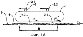
Фиг.1A-1C. Весьма схематичное изображение последовательных фаз работы первого примерного варианта реализации предлагаемого устройства, имеющего замкнутый путь и четыре инструмента, соединенных с двумя независимыми друг от друга приводами.Figa-1C. A very schematic representation of the successive phases of the first exemplary embodiment of the proposed device having a closed path and four tools connected to two independent from each other drives.
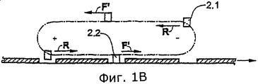
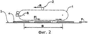
Фиг.2. Еще один примерный вариант реализации предлагаемого устройства, в котором по замкнутому пути обращаются пять инструментов, которые могут независимо друг от друга соединяться с приводом и отсоединяться от него.Figure 2. Another exemplary embodiment of the proposed device, in which five tools circulate in a closed path, which can independently connect to and disconnect from the drive.
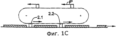
Фиг.3-5. Изображения, также весьма схематичные, еще трех вариантов реализации предлагаемого устройства, которые могут работать по принципу, показанному на фиг.1, или по принципу, представленному на фиг.2.Figure 3-5. Images, also very schematic, of three more embodiments of the proposed device, which can work according to the principle shown in figure 1, or according to the principle presented in figure 2.
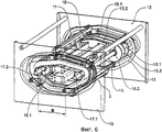
Фиг.6. Трехмерное изображение предпочтительного варианта реализации предлагаемого устройства (по принципу фиг.1) с обращением четырех инструментов в виде сварочной термопластины.6. A three-dimensional image of a preferred embodiment of the proposed device (according to the principle of FIG. 1) with the circulation of four tools in the form of a welding thermoplate.
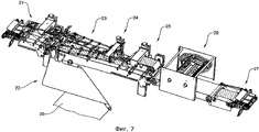
Фиг.7. Применение устройства с фиг.6 в установке для упаковки непрерывно подаваемых друг за другом плоских предметов посредством квазибесконечного пленочного полотна.7. The use of the device of FIG. 6 in an apparatus for packaging flat objects continuously fed one after another by means of a quasi-infinite film web.
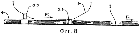
Фиг.8. Рабочая зона устройства согласно фиг.6 в увеличенном масштабе.Fig. 8. The working area of the device according to Fig.6 on an enlarged scale.
Фиг.9. Пример предлагаемого устройства с инструментами, шарнирно соединенными с твердым телом, которое установлено с возможностью вращения.Fig.9. An example of the proposed device with tools pivotally connected to a solid body, which is mounted for rotation.
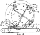
Фиг.10. Усовершенствованный вариант примера реализации изобретения согласно фиг.9, в котором инструменты могут перемещаться относительно твердого тела с двумя степенями свободы.Figure 10. An improved variant of the example embodiment of the invention according to Fig.9, in which the tools can move relative to a rigid body with two degrees of freedom.
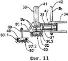
Фиг.11. Частичный вид устройства согласно фиг.10, показывающий водила.11. A partial view of the device of FIG. 10 showing a carrier.
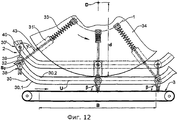
Фиг.12. Усовершенствованный вариант примера реализации изобретения согласно фиг.4, в котором инструменты могут перемещаться с двумя степенями свободы.Fig. 12. An improved variant of the example embodiment of the invention according to figure 4, in which the tools can move with two degrees of freedom.
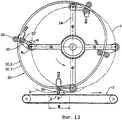
Фиг.13. Вариант устройства согласно фиг.9.Fig.13. A variant of the device according to Fig.9.
На фиг.1A-1C показаны последовательные фазы работы первого примера реализации заявляемого устройства. Это устройство имеет замкнутый путь 1 (показан штрихпунктирной линией), по которому обращаются четыре идентичных инструмента 2. Замкнутый путь 1 расположен, например, над поверхностью 3 подачи (например, над конвейерной лентой), на которой со скоростью F непрерывно подаются друг за другом на некотором расстоянии плоские предметы 4, обернутые в квазибесконечное пленочное полотно (не показано). При помощи инструментов полотно должно быть в промежутках между предметами 4 сварено и, возможно, разрезано. Замкнутый путь имеет рабочий участок В, на котором он, в сущности, проходит параллельно направлению конвейера, и участок обратного хода, на котором инструменты 2 после рабочего хода возвращаются в исходную точку для дальнейшей работы. Из четырех инструментов 2 инструменты с обозначением 2.1 жестко соединены с первым приводом, а инструменты с обозначением 2.2 - со вторым приводом, независимым от первого привода. Приводы не показаны.On figa-1C shows the successive phases of the first example implementation of the inventive device. This device has a closed path 1 (shown by a dash-dotted line) along which four
В фазе, показанной на фиг.1A, два инструмента (по одному инструменту из групп 2.1 и 2.2) находятся на рабочем участке B и перемещаются со скоростью F' рабочего хода, согласованной со скоростью F подачи, то есть оба привода работают со скоростью F' рабочего хода; два других инструмента, находящихся на участке обратного хода, перемещаются также со скоростью F' рабочего хода. В фазе, изображенной на фиг.1B, на рабочем участке B находится один инструмент из группы 2.2, то есть оба инструмента группы 2.2 приводятся в движение со скоростью F' рабочего хода. Инструмент группы 2.1, который на фиг.1A был еще на рабочем участке, покинул этот участок и вместе с другим инструментом группы 2.1 перемещается со скоростью R обратного хода, не зависящей от скорости F' рабочего хода. В этой фазе промежутки между инструментами обеих групп меняются.In the phase shown in figa, two tools (one tool from groups 2.1 and 2.2) are located on the working section B and move with the speed F 'of the stroke, consistent with the feed speed F, that is, both drives operate with speed F' working stroke; two other tools located in the reverse stroke section also move with the stroke speed F '. In the phase depicted in FIG. 1B, one tool from group 2.2 is located on the working section B, that is, both tools of group 2.2 are driven with the stroke speed F '. The tool of group 2.1, which was still in the working area in FIG. 1A, left this area and, together with another tool of group 2.1, moves with a reverse speed R independent of the working speed F '. In this phase, the gaps between the instruments of both groups change.
В фазе, показанной на фиг.1C, все инструменты снова приводятся в движение со скоростью F' рабочего хода.In the phase shown in FIG. 1C, all tools are again driven at the stroke speed F ′.
Оба привода управляются так, что инструменты поступают на участок обработки синхронно с обрабатываемыми предметами и с таким же тактированием, как и обрабатываемые предметы. Благодаря независимости обоих приводов можно, согласуя движения инструментов, реагировать на неравномерности в подаче, например, детектируемые посредством датчиков, в том числе оперативно, в частности, если инструмент уже перемещается на участок обработки.Both drives are controlled so that the tools arrive at the processing site in synchronism with the objects being processed and with the same timing as the objects being processed. Due to the independence of both drives, it is possible, by coordinating the movements of the tools, to respond to irregularities in the feed, for example, detected by sensors, including quickly, in particular, if the tool is already moving to the processing area.
Скорость F' рабочего хода и скорость R обратного хода необходимо устанавливать в зависимости от длины (протяженности в направлении подачи) предметов 4 (включая промежуток между предметами) и скорости F подачи. В представленном случае скорость F' рабочего хода равна скорости F подачи, а скорость R обратного хода больше скорости F' рабочего хода, так как длина предметов составляет меньше четверти замкнутого пути. Если длина предметов равна четверти длины замкнутого пути, то скорость обратного хода R равна скорости подачи. Если длина предметов 4 составляет более четверти длины замкнутого пути, то скорость R обратного хода может быть меньше или равна скорости F' рабочего хода, и инструменты каждой группы могут останавливаться в такой фазе работы, при которой на рабочем участке B нет ни одного инструмента группы.The speed F 'of the stroke and the speed R of the reverse stroke must be set depending on the length (length in the feed direction) of objects 4 (including the gap between the objects) and the speed F of the feed. In the presented case, the speed F 'of the stroke is equal to the feed speed F, and the speed R of the reverse stroke is greater than the speed F' of the stroke, since the length of the objects is less than a quarter of the closed path. If the length of the objects is equal to a quarter of the length of the closed path, then the reverse speed R is equal to the feed speed. If the length of the objects 4 is more than a quarter of the length of the closed path, then the speed R of the reverse stroke can be less than or equal to the speed F 'of the stroke, and the tools of each group can stop in such a phase of operation that there are no tools in the group B.
Устройство, схематично представленное на фиг.1, реализуют, например, с двумя цепными или ременными приводами, скорости которых не зависят друг от друга, причем с каждым из приводов жестко соединен каждый второй инструмент. Может быть желательно, способом, который сам по себе известен, присоединить инструменты к приводу с возможностью поворота, и так, что их угловым положением можно управлять независимо от локального направления замкнутой траектории и согласовывать его с обрабатываемыми предметами или полотном материала.The device, schematically shown in figure 1, is implemented, for example, with two chain or belt drives, the speeds of which are independent of each other, and with each drive every second tool is rigidly connected. It may be desirable, in a manner that is known per se, to attach the tools to the drive with the possibility of rotation, and so that their angular position can be controlled regardless of the local direction of the closed path and coordinate it with the workpiece or fabric material.
На фиг.2 в таком же схематичном виде, как и на фиг.1, показан еще один примерный вариант реализации предлагаемого устройства. На этих рисунках одни и те же детали обозначены одинаковыми номерами позиций. Это устройство также имеет замкнутый путь 1, по которому обращаются пять идентичных инструментов 2. При замкнутом пути предусмотрено два привода (не показаны): первый привод перемещает, по меньшей мере на рабочем участке B, соединенные с ним инструменты 2 со скоростью F' рабочего хода, согласованной со скоростью F подачи, а второй привод возвращает соединенные с ним инструменты 2 со скоростью R обратного хода от выхода рабочего участка B назад к его входу. На входе рабочего участка B предусмотрено средство S останова или другое средство управления, которое останавливает отводимый инструмент и таким образом полностью или частично отсоединяет его от второго привода и опционально накапливает инструменты, а также для каждого рабочего хода отпускает на рабочий участок B первый в накопителе инструмент, для чего соединяет его с первым приводом. Торможение можно осуществлять также посредством управления вторым приводом.Figure 2 in the same schematic form as in figure 1, shows another exemplary embodiment of the proposed device. In these figures, the same parts are denoted by the same reference numbers. This device also has a
Ясно, что при помощи устройства, изображенного на фиг.2, можно обрабатывать предметы различной длины (в том числе расположенные на различных расстояниях), при этом необходимо лишь настроить средство управления, а изменение скорости R обратного хода не требуется. Понятно, что средство управления может отпускать инструменты либо тактировано, то есть согласовано с тактом подачи обрабатываемых предметов, либо с управлением от датчиков, всякий раз, когда детектируется предмет или позиция рабочего прохода.It is clear that using the device shown in FIG. 2, it is possible to process objects of various lengths (including those located at different distances), all that is needed is to adjust the control means, and changing the reverse speed R is not required. It is clear that the control tool can release the tools either in a clocked manner, that is, coordinated with the cycle rate of the processed objects, or with control from sensors, whenever an object or position of the working passage is detected.
Разумеется, в изображенном на фиг.1 устройстве можно предусмотреть только один привод, так что скорость R обратного хода равна скорости F' рабочего хода. Чтобы посредством этого устройства можно было обрабатывать даже предметы очень малой длины, необходимо предусмотреть соответствующее количество инструментов.Of course, only one drive can be provided in the device shown in FIG. 1, so that the reverse speed R is equal to the working speed F '. In order to process even objects of very short lengths with this device, an appropriate number of tools must be provided.
Привод, подходящий для устройства согласно фиг.2, описан, например, в публикации № EP-1232974 (или US-6607073). Речь идет о приводе, основанном на принципе вихревых токов; инструменты к нему могут присоединяться и отсоединяться посредством несложного механического упора, стопорящего и деблокирующего эти инструменты. Также, особенно если предусмотрен только один привод (скорость F' рабочего хода равна скорости R обратного хода), можно использовать цепной привод, с которым можно избирательно соединять инструменты. Такие приводы описаны, например, в публикациях №№ CH-618398 (или US-4201286), EP-276409 (или US-4892186) и EP-309702 (или US-4887809).An actuator suitable for the device of FIG. 2 is described, for example, in Publication No. EP-1232974 (or US-6607073). It is a drive based on the principle of eddy currents; tools can be attached and disconnected to it by means of a simple mechanical stop that locks and unlocks these tools. Also, especially if only one drive is provided (the travel speed F 'is equal to the reverse speed R), a chain drive can be used with which tools can be selectively connected. Such drives are described, for example, in Publication Nos. CH-618398 (or US-4201286), EP-276409 (or US-4892186) and EP-309702 (or US-4887809).
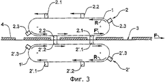
На фиг.3-5 в таком же весьма схематичном виде, как и на фиг.1, показаны дополнительные варианты реализации предлагаемого устройства. От устройств согласно фиг.1 и 2 они отличаются, в частности, формой замкнутого пути 1, количеством обращающихся по этому пути инструментов 2 и/или исполнением сопряженных инструментов. Во всех представленных случаях инструменты показаны так, будто они в каждом случае приводятся в движение одним приводом на группу (по принципу фиг.1). Разумеется, инструменты во всех вариантах реализации могут приводиться в движение также в соответствии с принципом, представленным на фиг.2.Figure 3-5 in the same very schematic form as in figure 1, shows additional embodiments of the proposed device. They differ from the devices according to FIGS. 1 and 2, in particular, in the shape of the
На фиг.3 показано сочетание двух заявляемых устройств, причем первое устройство (путь 1 и инструменты 2) расположено над обрабатываемыми предметами 4 или полотном материала, а второе устройство (путь 1' и сопряженные инструменты 2') - под ними. Между синхронно приводимыми в движение инструментами 2 и сопряженными с ними инструментами 2' перемещаются предметы 4 или полотно, например, на поверхности подачи 3 (например, на конвейерной ленте), причем при обработке сопряженные инструменты 2' подпирают поверхность подачи. Если обрабатывают достаточно прочное полотно материала, и разрезание полотна в обработку не входит, можно также отказаться от поверхности подачи 3 и обрабатывать между инструментами 2 и сопряженными инструментами 2' только полотно (возможно, с предметами 4).Figure 3 shows a combination of the two claimed devices, the first device (
Шесть инструментов 2 и шесть сопряженных инструментов 2' перемещаются группами (2.1, 2.2 и 2.3 или, соответственно, 2'.1, 2'.2 и 2'.3), которые в каждом случае приводятся в движение одним из трех не зависящих друг от друга приводов (не показаны). В фазе, показанной на фиг.3, группы 2.1, 2.2, 2'.1 и 2'.2 перемещаются со скоростью F' рабочего хода, а группы 2.3 и 2'.3 - со скоростью R обратного хода.Six
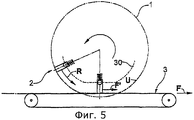
На фиг.4 показано еще одно сочетание двух заявляемых устройств, в котором взаимодействуют инструменты 2 и сопряженные инструменты 2'. Оба замкнутых пути 1 и 1' круговые, причем упругой установкой инструментов 2 и/или сопряженных инструментов 2' обеспечивается, что траектории U взаимодействующих с полотном удаленных концов инструментов (ниже они обозначаются также как рабочий орган 38) на рабочем участке B выпрямлены и ориентированы параллельно направлению подачи. Каждая из двух групп инструментов и сопряженных инструментов установлена, например, на вращающемся колесе (не показано).Figure 4 shows another combination of the two claimed devices in which the
Вместо чисто упругой установки инструментов 2 вдоль радиально ориентированной направляющей 31 может существовать, по меньшей мере, на части траектории 1, направляющий копир 30 (показан штрихпунктирной линией), взаимодействующий с инструментами 2. Посредством копира 30 можно регулировать расстояние d между инструментами и центром вращения D. В этом случае инструменты 2, способные перемещаться в радиальном направлении вдоль направляющей 31, либо установленные на инструментах 2 директоры 32, пружиной 33 прижаты к направляющему копиру 30. В качестве замкнутого пути 1 следует рассматривать траекторию любой точки на направляющих 31; здесь для примера обозначена траектория дистального конца направляющей 31. Без воздействия направляющего копира 30 инструменты 2 отжимаются в их наружное радиальное положение (расстояние d соответствует радиусу траектории 1); под действием направляющего копира 30 расстояние d управляемо уменьшается.Instead of a purely elastic installation of the
На рабочем участке B инструменты 2 копиром 30 отводятся, преодолевая силу пружины, к центру вращения. Как описано выше, благодаря действию копира 30 траектория U удаленных концов инструментов по сравнению с чисто круговой орбитой выпрямляется. Благодаря этому на поверхность 3 подачи или сопряженные инструменты 2' действует только точно дозируемая, неизменяющаяся сила. Концы инструментов всегда ориентированы в радиальном направлении.At work area B, the
Если инструменты направляются копиром 30 вдоль всей траектории 1, то отпадает также необходимость подпружинивания.If the tools are guided by the
Отклонение траектории движения инструментов от круговой путем управления движением инструментов с помощью копира можно использовать и в том случае, если инструменты приводятся в движение не независимо друг от друга, как например, в устройствах, имеющих только один инструмент, перемещающийся по круговой траектории. Сопряженное устройство (не показано) можно выполнить аналогично. В частности, сопряженные инструменты 2', как и инструменты 2, также могут управляться направляющими копирами.The deviation of the tool path from the circular one by controlling the movement of the tools with the help of a copier can also be used if the tools are not independently driven, such as in devices that have only one tool moving in a circular path. A paired device (not shown) can be performed similarly. In particular, the mating tools 2 ', like the
На фиг.5 показано заявляемое устройство с круговой траекторией 1 и двумя инструментами 2, причем инструменты взаимодействуют с поверхностью 3 подачи и установлены упруго. Каждый из этих двух инструментов приводится в движение собственным приводом (не показан).Figure 5 shows the inventive device with a
Здесь также можно применить копир 30, обеспечивающий выпрямление траектории U дистальных концов инструментов относительно их собственной траектории 1 движения. В этом случае на опорную поверхность 3 будет действовать лишь незначительная, точно определенная сила. Траекторию инструментов 2 может быть оптимальным образом задана относительно поверхности подачи 3.Here you can also apply a
На фиг.6 в деталях показан предпочтительный вариант предлагаемого устройства. В сущности, оно соответствует устройству, схематично изображенному на фиг 1. Четыре представленные инструмента 2 имеют опорные балки 10 и сварочные термопластины 11, укрепленные на опорных балках 10, причем балки 10 и пластины 11 расположены между двумя стенками 12. На обращенных друг к другу сторонах обеих стенок 12 установлены направляющие 13, которые определяют замкнутый путь инструментов 2 и направляют с возможностью вращения, или, по меньшей мере, качания опорные балки 10, так что во время движения инструментов по замкнутому пути посредством неподвижного копира положение сварочных пластин относительно пути может меняться. Каждая вторая опорная балка соединена с первым ременным приводом. Первый ременный привод имеет два зубчатых ремня 15.1. Ремни, к которым прикреплены концы опорных балок 10, движутся по двум зубчатым колесам 16.1, которые установлены парами соосно, причем одна пара соосных колес приведена в движение первым приводным валом 17.1. Другие две опорные балки 10 соединены со вторым ременным приводом, то есть они также прикреплены к двум зубчатым ремням 15.2, которые также движутся по двум зубчатым колесам 16.2, установленным соосно зубчатым колесам 16.1 первого ременного привода; два зубчатых колеса приводятся в движение вторым приводным валом 17.2. Зубчатые ремни 15.1 и 15.2, которые кроме зубчатых колес направляются также дополнительными направляющими деталями, движутся парами по замкнутому пути, согласованному с путем опорных балок 10. Путь сварочных термопластин 11 задан не только движением опорных балок 10, но также их качанием.Figure 6 shows in detail the preferred embodiment of the proposed device. In essence, it corresponds to the device schematically depicted in Fig. 1. The four tools presented 2 have
Показанное на фиг.6 устройство отличается не только гибкостью в отношении размеров упаковываемых предметов, но и своей тихой работой, в частности, по сравнению с устройствами с кривошипным механизмом или движущимися возвратно-поступательно деталями.The device shown in Fig.6 is not only flexible in terms of the size of the packed items, but also in its quiet operation, in particular compared to devices with a crank mechanism or moving reciprocating parts.
На фиг.7 показано применение устройства согласно фиг.6. Это устройство применяется в установке для упаковки плоских предметов, например, печатных изделий, посредством квазибесконечного пленочного полотна 20, для сварки полотна 20 в поперечном направлении в промежутках между предметами и, при необходимости, резки полотна 20, перед этим обернутого вокруг предметов (не показаны), непрерывно подаваемых друг за другом с промежутками между ними.In Fig.7 shows the use of the device according to Fig.6. This device is used in an apparatus for packing flat objects, for example, printed products, by means of a
Эта установка имеет известные рабочие участки, выполняющие следующие функции: подача плоских предметов (участок 21), подача квазибесконечного пленочного полотна 20 (участок 22), обертывание пленочного полотна 20 вокруг ряда плоских предметов (участок 23), продольная сварка полотна 20 (участок 24), прессование ряда предметов, обернутых пленкой (участок 25), поперечная сварка и резка полотна 20 между предметами (участок 26) и отгрузка отдельно упакованных плоских предметов (участок 27).This installation has known working sections that perform the following functions: feeding flat objects (section 21), feeding a quasi-infinite film web 20 (section 22), wrapping the
На фиг.8 в немного увеличенном масштабе показана рабочая зона устройства согласно фиг.6. Из фиг.8 видно, что по концам рабочего участка, где инструменты воздействуют на пленочное полотно и для этой цели движутся со скоростью полотна, имеются зона подвода, в которой инструменты приближаются к полотну и, в частности, подводятся между следующими друг за другом предметами, и зона отвода, где инструменты отводятся от полотна и, в частности, выводятся между следующими друг за другом предметами. Желательно, чтобы в зоне подвода и в зоне отвода сварочные термопластины были направлены перпендикулярно полотну, а также приближались и удалялись от него по возможности тоже перпендикулярно (нулевая или, в крайнем случае, минимальная относительная скорость между инструментом и полотном в направлении подачи). Это достигается качанием в зоне подвода и в зоне отвода опорных балок таким образом, что сварочные пластины направлены перпендикулярно полотну. Кроме того, путь 1 в зоне подвода и зоне отвода желательно иметь, в основном, прямолинейный, а скорость инструментов, для компенсации наклона траектории, немного больше скорости F' рабочего хода. Благодаря этой компенсации можно весьма точно вводить сварочные пластины в промежутки между предметами и выводить их, вследствие чего эти промежутки могут быть ограничены до минимума даже при сравнительно толстых предметах, что в случае большого количества предметов означает существенную экономию пленки.On Fig in a slightly enlarged scale shows the working area of the device according to Fig.6. From Fig. 8 it can be seen that at the ends of the working section, where the tools act on the film web and for this purpose move at the speed of the web, there is a feed zone in which the tools approach the web and, in particular, are brought between successive objects, and a retreat zone, where the tools are retracted from the canvas and, in particular, are displayed between successive objects. It is desirable that in the supply zone and in the withdrawal zone the welding thermoplates are directed perpendicular to the sheet, and also approach and move away from it, if possible, also perpendicular (zero or, in extreme cases, the minimum relative speed between the tool and the sheet in the feed direction). This is achieved by swinging in the supply zone and in the zone of removal of the support beams so that the welding plates are directed perpendicular to the sheet. In addition, it is desirable to have a
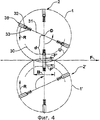
На фиг.9 показан пример заявляемого устройства с двумя водилами 34 в виде спиц, установленных с возможностью вращения вокруг центра D. На дистальных концах водил 34 помещено по одному инструменту 2. Обе спицы 34, как и в примере из фиг.4, могут быть приведены в движение независимо друг от друга, так что можно варьировать угол между ними, а вместе с тем и расстояние между инструментами. Если же постоянный угол или расстояние между инструментами удовлетворяет решаемой задаче, водила 34 можно соединить друг с другом жестко, и/или применять один привод. Также может использоваться единственный инструмент 2.Figure 9 shows an example of the inventive device with two
Здесь инструменты 2 имеют рабочий орган 38, в данном случае взаимодействующий с обрабатываемым предметом или полотном материала. Рабочий орган 38 содержит, например, сварочный аппарат 38.1 и прижим 38.2. Первый конец 36 рычага 35 соединен с удаленной концевой частью водила 34 с возможностью вращения вокруг оси S1. Рабочий орган 38 установлен на рычаге 35 на некотором расстоянии от оси S1. Угол α между рычагом 35 или его осью и водилом 34 может меняться. Угол γ между рычагом 35 и направлением действия рабочего органа 38, которое определено ориентацией сварочного аппарата 38.1 и прижима 38.2, в данном примере постоянен и составляет примерно 90°, но в усовершенствованном варианте реализации этот угол может меняться (фиг.10).Here, the
Рычаги 35 имеют директор 32, в данном случае в виде ролика, взаимодействующего с неподвижным копиром 30 в виде кольцевой канавки. Благодаря этому можно регулировать угловое положение рычага 35 относительно водила 34, а вместе с тем и угловое положение инструментов 2 относительно кругового пути 1. Благодаря этому также можно регулировать расстояние d между рабочими органами 38 и центром вращения. Здесь направляющий копир 30 имеет такую форму, что расстояние d всегда больше или равно радиусу r пути 1, причем на рабочем участке B расстояние d меняется так, что создается траектория U с приблизительно прямым участком. Благодаря этому, на рабочем участке В также удается создать, по меньшей мере, на определенных участках, приблизительно постоянный угол β, в данном случае примерно от 90 до 100°, между поверхностью 3 подачи и рабочим органом 38.The
Направляющий копир 30 в виде кольцевой канавки образован двумя направляющими поверхностями 30.1, 30.2, которые расположены на некотором расстоянии друг от друга и ведут директор 32 с обеих сторон и, таким образом, задают расстояние d, а вместе с тем и ориентацию рабочего органа в пространстве, то есть угол β относительно поверхности подачи. Для получения траектории U с прямым участком направляющий копир 30 на рабочем участке B имеет ровные направляющие поверхности 30.1, 30.2, проходящие параллельно поверхности 3 подачи. Если рычаг 35 прижат пружиной к одной из направляющих поверхностей 30.1, 30.2, то другая направляющая поверхность становится лишней.The
Рычаги 35, а вместе с ними и рабочие органы 38 в виде качающегося рычага тянутся за водилами 34 в направлении вращения. На рабочем участке B их вес, по меньшей мере, частично, воспринимается копиром 30. Остающаяся сила служит для прижима рабочих органов 38 к поверхности 3 подачи. В показанном примере благодаря этому изменяется расстояние между рабочими органами прижима 38.2 и сварочного аппарата 38.1, так что можно сваривать полотно 20 материала.The
На фиг.10 показан усовершенствованный вариант устройства, изображенного на фиг.9. В этом варианте расстояние d между рабочим органом 38 и центром D вращения и ориентацию рабочего органа 38 в пространстве, то есть угол β относительно поверхности 3 подачи, можно регулировать независимо друг от друга. Благодаря этому, на более значительной части траектории U рабочих органов 38 можно создать участки, на которых траектория U проходит параллельно поверхности 3 подачи, а рабочие органы 38 имеют в пространстве требуемую ориентацию.Figure 10 shows an improved version of the device depicted in figure 9. In this embodiment, the distance d between the working
Как и на фиг.9, рабочий орган 38 соединен с водилом 34 с возможностью поворота. Как показано на фиг.11, рычаг, соединяющий рабочий орган 38 и водило 34, выполнен в виде двойного рычага, охватывающего U-образную первую часть 35 рычага и помещенную в нее вторую часть 37, которая установлена упруго относительно первой части 35. Двойной рычаг 35/37 как целое может поворачиваться вокруг оси S1, причем обе части рычага 35, 37 могут наклоняться относительно друг друга. Рабочий орган 38 находится на второй части 37 рычага; директор 32, взаимодействующий с первым направляющим копиром 30, установлен на первой части 35 рычага. Как указано в описании фиг.9, расстояние d регулируется благодаря тому, что при помощи первого копира 30 варьируют угол α между первым рычагом 35/37 и водилом 34. Однако рабочий орган 38 ненеподвижен, он соединен с первым рычагом 35 с возможностью поворота вокруг второй оси S2. При этом угол γ между первым рычагом 35/37 и рабочим органом 38 можно устанавливать независимо от угла α. Для этого предназначен второй направляющий копир 30', взаимодействующий с еще одним директором 40, здесь также в виде направляющего ролика. Дополнительный директор 40 посредством второго рычага 39 соединен с рабочим органом 38. Он находится на некотором расстоянии от дополнительной оси S2 поворота. Поскольку сохранено расстояние до соответствующей оси поворота S1 или S2, в общем, директоры 32, 40 могут находиться в любом положении на первом или втором рычаге 35/37 или 39. Рабочий орган 38 может находиться на втором рычаге 39 также в любом месте.As in figure 9, the working
Благодаря первому рычагу с первой частью 35 рычага и упруго установленной относительно нее второй частью 37 рычага рабочий орган 38 может сдвигаться относительно директора 32, например, чтобы при очень толстых предметах или скоплении предметов отойти от траектории, заданной первым копиром 30. В этом случае ось поворота S1, которая обычно находится на одной линии с осью директора 32, сдвигается относительно нее. Благодаря этому повышается гибкость и надежность предлагаемого устройства. Такую меру можно предусмотреть и в устройстве, представленном на фиг.9.Thanks to the first lever with the
Направляющие копиры 30, 30' также включают две направляющие поверхности 30.1, 30.2 или 30'. 1, 30'.2, разнесенные в радиальном направлении на некоторое расстояние друг от друга. Пружина 42 прижимает первые рычаги 35 к расположенной по внешнему радиусу направляющей поверхности 30.1 первого копира 30. Чтобы траектории директоров 32, 40 могли пересекаться, эти траектории движения лежат в разных плоскостях, параллельных плоскости изображения, как показано на фиг.11.
Несмотря на чисто вращательное движение водил, показанный на фиг.10 и 11 усовершенствованный вариант реализации устройства с рабочим органом, двумя поворотными рычагами шарнирно соединенным с вращающимся водилом, позволяет получить прямолинейную траекторию движения рабочих органов, а также управляемую их ориентацию в пространстве, по меньшей мере, на некоторых участках.Despite the purely rotational movement of the carrier, shown in FIGS. 10 and 11 an improved embodiment of the device with a working body, two pivoting arms pivotally connected to a rotating carrier, allows to obtain a rectilinear trajectory of the movement of the working bodies, as well as their controlled orientation in space, at least , in some areas.
Для стабилизации всего устройства, показанная на фиг.9 и 10 компоновка может быть выполнена в зеркальной симметрии относительно плоскости, параллельной плоскости изображения. Например, водила 34 могут находиться зеркально-симметрично по обе стороны поверхности 3 подачи. Рабочие органы 38 можно установить на удлиненных балках 41, расположенных перпендикулярно плоскости изображения и закрепленных своими наружными концами на водиле 34, и образующих, например, вторую ось S2 поворота (фиг.11). При первых осях S1 поворота также могут быть установлены стабилизирующие пружины 42.To stabilize the entire device, shown in Fig.9 and 10, the layout can be made in mirror symmetry relative to a plane parallel to the image plane. For example,
На фиг.12 показан вариант изображенного на фиг.4 устройства, в котором, помимо изменения первым направляющим копиром 30 расстояния d между рабочим органом 38 и центром D вращения, второй направляющий копир 30' управляет ориентацией рабочего органа 38. В результате, как и в примере на фиг.10, рабочий орган 38 имеет две степени свободы, и, несмотря на чисто вращательное движение привода, можно с большей точностью получить необходимую траекторию U и требуемую ориентацию рабочих органов.On Fig shows a variant of the device shown in figure 4, in which, in addition to changing the
Как и в примере на фиг.4, инструмент 2 установлен на вращающемся водиле 34, в данном случае в виде колеса, и может сдвигаться в радиальном направлении, то есть перпендикулярно оси вращения. Положение его на рабочем участке изображено сплошными линиями. Два других положения, перед входом на рабочий участок и у его конца, обозначены пунктирными линиями. Для радиального движения в направляющей втулке 31' имеется подвижный шток 43, толкаемый наружу пружиной 33. На дистальном конце штока 43 находится директор 32 в виде ролика, который направляется первым копиром 30, по меньшей мере, на рабочем участке В. Рабочий орган 38 соединен с дистальным концом штока с возможностью поворота вокруг оси S2. Поскольку директор 32 во время вращения водила 34 скользит вдоль первого копира 30, изменяется расстояние d. Здесь первый копир 30 имеет такую форму, что траектория U рабочих органов 38 на рабочем участке B проходит параллельно поверхности 3 подачи. Притом направляющие поверхности 30.1, 30.2 первого копира 30 также проходят параллельно поверхности 3, по меньшей мере, на некоторых участках. Так как рабочие органы 38 подпружинены наружу, достаточно, чтобы первый копир 30 находился только на том участке замкнутого пути 1, который соответствует рабочему участку.As in the example of FIG. 4, the
Рабочий орган 38 посредством рычага 39 соединен со вторым директором 40, выполненным также в виде ролика. Благодаря тому, что директор 40 во время вращения водила 34 скользит вдоль второго копира 30', задается угол γ между рабочим органом 38 и штоком 43. В данном случае второй копир 30' имеет такую форму, что ориентация рабочего органа 38 в пространстве или относительно поверхности 3 подачи остается постоянной, по меньшей мере, на рабочем участке B. Таким образом, на рабочем участке B можно задать постоянный угол, в данном случае примерно 90°, то есть перпендикулярно полотну материала. Также можно опускать рабочий орган на полотно в этой ориентации.The working
Как и в описанных выше случаях, первый копир 30 помогает дозировать силу, действующую на поверхность 3 подачи. В наличии может быть один или несколько инструментов. В случае нескольких инструментов, их можно приводить в движение синхронно или с различными скоростями.As in the cases described above, the
На фиг.13 показан еще один пример осуществления изобретения, который в основном соответствует конструкции, изображенной на фиг.9. На дистальных концах четырех спицеобразных водил 34 посредством рычагов 35, движущихся в направлении обращения, установлен поворотный инструмент 2. Поворот, то есть угол α между рычагом 35 и водилом 34, задается копиром 30. Здесь копир 30 выполнен не в виде канавки, как на фиг.9, а имеет форму сплошного кольца с двумя наружными окружными направляющими поверхностями 30.1, 30.2. Поверхности 30.1, 30.2 обегаются парой директоров 32, 32'. Благодаря спрямлению копира 30 на рабочем участке можно получить траекторию U рабочих органов 38, проходящую параллельно поверхности 3 подачи, по меньшей мере, на некоторых участках.On Fig shows another example embodiment of the invention, which basically corresponds to the design shown in Fig.9. A
В противоположность устройству согласно фиг.4, в котором рабочие органы 38 всегда направлены радиально, в этом варианте, за счет шарнирного присоединения рабочего органа 38 через рычаг 35 к водилу 34 можно достичь приблизительно постоянной ориентации рабочего органа 38 относительно поверхности 3 подачи, по меньшей мере, на рабочем участке. Однако доля траектории U, на которой она проходит параллельно поверхности 3 подачи и на протяжении которой угол β меняется незначительно, меньше, чем, например, на фиг.10 и 12.In contrast to the device according to figure 4, in which the working
Как и на фиг.9 и 10, в зависимости от требований угол между соответствующей парой спиц можно оставлять неизменным или менять его посредством дополнительного привода.As in FIGS. 9 and 10, depending on the requirements, the angle between the corresponding pair of spokes can be left unchanged or changed using an additional drive.
Claims (52)
- по меньшей мере, один инструмент, приводимый в обращение по замкнутому пути;
- средства привода для перемещения по меньшей мере одного инструмента по пути обращения инструментов;
- средства управления средствами привода;
- причем путь обращения инструментов имеет рабочий участок, расположенный, по существу, параллельно направлению подачи предметов или полотна;
- причем предметы или полотно можно обрабатывать посредством, по меньшей мере, одного инструмента, перемещаемого по рабочему участку, и причем, по меньшей мере, один инструмент средствами привода может быть перемещаем по рабочему участку со скоростью рабочего хода, согласованной со скоростью подачи,
и причем, по меньшей мере, один инструмент установлен с возможностью управляемого поворота относительно пути обращения инструментов таким образом, что независимо от направления пути его угловое положение управляемо согласовано с подлежащими обработке предметами или полотном.1. A device for processing continuously fed one after another with a feed rate of flat objects or continuously fed quasi-infinite web of material, containing:
- at least one tool that is circulated in a closed path;
- drive means for moving at least one tool along the tool path;
- drive controls;
- moreover, the path of circulation of the tools has a working section located essentially parallel to the direction of supply of objects or paintings;
- moreover, objects or canvas can be processed by means of at least one tool that is moved around the work area, and moreover, at least one tool by means of the drive can be moved along the work area with the speed of the stroke, consistent with the feed rate,
and moreover, at least one tool is installed with the possibility of controlled rotation relative to the path of circulation of the tools in such a way that regardless of the direction of the path, its angular position is controllably coordinated with the objects or sheet to be processed.
- инструменты, приводимые в обращение по замкнутому пути;
- средства привода для перемещения инструментов по пути обращения;
- средства управления средствами привода;
- причем путь обращения инструментов содержит рабочий участок, расположенный, по существу, параллельно направлению подачи предметов или полотна;
- причем предметы или полотно могут обрабатываться посредством инструментов, перемещаемых по рабочему участку;
- и причем инструменты средствами привода могут перемещаться по рабочему участку со скоростью рабочего хода, согласованной со скоростью подачи;
- и причем средства привода предназначены для перемещения по замкнутому пути групп инструментов или отдельных инструментов независимо от других групп инструментов или независимо от других отдельных инструментов таким образом, что различные инструменты на пути обращения могут одновременно приводиться в движение с разными скоростями.27. A device for processing continuously fed one after another with a feed rate of flat objects or continuously fed quasi-infinite web of material, containing:
- instruments that are circulated in a closed path;
- drive means for moving tools along the path of circulation;
- drive controls;
- moreover, the path of circulation of the tools contains a working area located essentially parallel to the direction of supply of objects or paintings;
- moreover, objects or canvas can be processed using tools moved around the work area;
- and whereby the tools by means of the drive can move along the working area with the speed of the stroke, consistent with the feed rate;
- and moreover, the drive means are designed to move on a closed path groups of tools or individual tools independently of other groups of tools or independently of other individual tools in such a way that various tools on the path of circulation can simultaneously be driven at different speeds.
Applications Claiming Priority (2)
| Application Number | Priority Date | Filing Date | Title |
|---|---|---|---|
| CH1001/06 | 2006-06-21 | ||
| CH10012006 | 2006-06-21 |
Publications (2)
| Publication Number | Publication Date |
|---|---|
| RU2009101001A RU2009101001A (en) | 2010-07-27 |
| RU2430863C2 true RU2430863C2 (en) | 2011-10-10 |
Family
ID=37310837
Family Applications (1)
| Application Number | Title | Priority Date | Filing Date |
|---|---|---|---|
| RU2009101001/21A RU2430863C2 (en) | 2006-06-21 | 2007-03-08 | Device for processing continuously fed flat items or quasi-endless web of material |
Country Status (12)
| Country | Link |
|---|---|
| US (1) | US8417369B2 (en) |
| EP (2) | EP2029438B1 (en) |
| JP (1) | JP5048766B2 (en) |
| AT (1) | ATE468270T1 (en) |
| AU (1) | AU2007262577B2 (en) |
| CA (1) | CA2656026C (en) |
| DE (1) | DE502007003866D1 (en) |
| DK (2) | DK2029438T3 (en) |
| ES (1) | ES2346583T3 (en) |
| PL (1) | PL2029438T3 (en) |
| RU (1) | RU2430863C2 (en) |
| WO (1) | WO2007147269A1 (en) |
Families Citing this family (7)
| Publication number | Priority date | Publication date | Assignee | Title |
|---|---|---|---|---|
| DE102008002246A1 (en) * | 2008-06-05 | 2009-12-10 | Robert Bosch Gmbh | Cutting device for endless hose system |
| EP2149831B1 (en) * | 2008-07-31 | 2012-02-01 | Siemens Aktiengesellschaft | Control method for a composite of several multi-axle handling devices arranged behind or beside each other and data storage medium, control system and composite |
| CH699596A1 (en) | 2008-09-25 | 2010-03-31 | Ferag Ag | Device and method for processing of goods. |
| CH700866A2 (en) | 2009-04-28 | 2010-10-29 | Ferag Ag | Apparatus and method for packaging of objects. |
| CH704455A1 (en) * | 2011-02-09 | 2012-08-15 | Ferag Ag | Method and apparatus for packaging products. |
| US8713730B2 (en) | 2011-05-31 | 2014-05-06 | Lawrence R. Koh and Nina Merrell-Koh | Medical transport device |
| FR3063522B1 (en) | 2017-03-06 | 2021-05-07 | Safran Nacelles | ACTUATION DEVICE FOR A THRUST INVERTER WITH ANTI-DEPLOYMENT BODY |
Family Cites Families (19)
| Publication number | Priority date | Publication date | Assignee | Title |
|---|---|---|---|---|
| GB1261179A (en) | 1969-02-26 | 1972-01-26 | Sitma Soc It Macchine Automati | Device for welding and cutting films of plastics materials in apparatus for packing goods |
| GB1507085A (en) | 1975-11-12 | 1978-04-12 | Baker Perkins Holdings Ltd | Wrapping machines |
| CH618398A5 (en) | 1977-06-06 | 1980-07-31 | Ferag Ag | |
| US4300977A (en) * | 1978-10-24 | 1981-11-17 | Karl Heinz Stiegler | Machine for welding thermoplastic sheets |
| DE3779418D1 (en) | 1987-01-26 | 1992-07-02 | Ferag Ag | CLOCK CONVEYOR. |
| CH680285A5 (en) | 1987-10-02 | 1992-07-31 | Ferag Ag | |
| IT1274112B (en) | 1994-11-15 | 1997-07-15 | C M C Srl | EQUIPMENT FOR WRAPPING ITEMS WITH A CONTINUOUS SHEET |
| US5755923A (en) | 1996-11-26 | 1998-05-26 | Owens-Corning Fiberglas Technology, Inc. | Heat seal apparatus |
| IT1295146B1 (en) * | 1997-07-31 | 1999-04-30 | Fosber Spa | CORD CUTTING MACHINE WITH INDEPENDENT CUTTING TOOLS AND RELATIVE ORDER CHANGE METHOD |
| EP0945349B1 (en) | 1998-03-27 | 2004-01-02 | SIG Pack Systems AG | Device for transversal sealing and cutting of a thermoplastic packaging tube, especially for tubular bag packaging machines |
| CA2291898C (en) | 1998-12-11 | 2006-01-24 | Vision Verpackungstechnik Gmbh | Equipment for the process of continuously feeding packaging material |
| EP1031401B1 (en) * | 1999-02-25 | 2003-07-02 | FOSBER S.p.A. | Apparatus for the transverse cutting of weblike material |
| US6481188B1 (en) | 2000-06-30 | 2002-11-19 | Owens Corning Fiberglas Technology, Inc. | Apparatus and method for sealing an article |
| AU783789B2 (en) | 2001-02-07 | 2005-12-08 | Denipro Ag | Conveyor system |
| JP4253164B2 (en) * | 2002-05-17 | 2009-04-08 | 株式会社イシダ | Horizontal seal mechanism of bag making and packaging machine and bag making and packaging machine |
| ES2319979T3 (en) * | 2002-08-20 | 2009-05-18 | Ferag Ag | DEVICE FOR THE TREATMENT OF FLAT OBJECTS, ESPECIALLY FOR PACKING PRINTED PRODUCTS. |
| ES2302196T3 (en) * | 2004-06-02 | 2008-07-01 | Ferag Ag | METHOD AND DEVICE FOR PACKING FLAT OBJECTS. |
| DK1751005T3 (en) * | 2004-06-02 | 2008-07-14 | Ferag Ag | Method and device for packaging flat articles |
| JP4003792B2 (en) * | 2004-11-17 | 2007-11-07 | オムロン株式会社 | Servo motor control system |
-
2007
- 2007-03-08 RU RU2009101001/21A patent/RU2430863C2/en not_active IP Right Cessation
- 2007-03-08 CA CA2656026A patent/CA2656026C/en not_active Expired - Fee Related
- 2007-03-08 ES ES07701928T patent/ES2346583T3/en active Active
- 2007-03-08 DE DE502007003866T patent/DE502007003866D1/en active Active
- 2007-03-08 DK DK07701928.9T patent/DK2029438T3/en active
- 2007-03-08 EP EP07701928A patent/EP2029438B1/en not_active Not-in-force
- 2007-03-08 EP EP10002983A patent/EP2208680B1/en not_active Not-in-force
- 2007-03-08 US US12/305,274 patent/US8417369B2/en not_active Expired - Fee Related
- 2007-03-08 JP JP2009515684A patent/JP5048766B2/en not_active Expired - Fee Related
- 2007-03-08 AT AT07701928T patent/ATE468270T1/en active
- 2007-03-08 AU AU2007262577A patent/AU2007262577B2/en not_active Ceased
- 2007-03-08 DK DK10002983.4T patent/DK2208680T3/en active
- 2007-03-08 WO PCT/CH2007/000130 patent/WO2007147269A1/en active Application Filing
- 2007-03-08 PL PL07701928T patent/PL2029438T3/en unknown
Also Published As
| Publication number | Publication date |
|---|---|
| US8417369B2 (en) | 2013-04-09 |
| CA2656026C (en) | 2015-09-01 |
| AU2007262577A1 (en) | 2007-12-27 |
| WO2007147269A1 (en) | 2007-12-27 |
| US20090228140A1 (en) | 2009-09-10 |
| EP2208680A1 (en) | 2010-07-21 |
| DE502007003866D1 (en) | 2010-07-01 |
| EP2029438B1 (en) | 2010-05-19 |
| ATE468270T1 (en) | 2010-06-15 |
| RU2009101001A (en) | 2010-07-27 |
| AU2007262577A2 (en) | 2009-05-21 |
| ES2346583T3 (en) | 2010-10-18 |
| PL2029438T3 (en) | 2010-10-29 |
| AU2007262577B2 (en) | 2013-01-17 |
| EP2208680B1 (en) | 2013-02-20 |
| CA2656026A1 (en) | 2007-12-27 |
| JP2009541147A (en) | 2009-11-26 |
| JP5048766B2 (en) | 2012-10-17 |
| DK2208680T3 (en) | 2013-05-21 |
| EP2029438A1 (en) | 2009-03-04 |
| DK2029438T3 (en) | 2010-09-13 |
Similar Documents
| Publication | Publication Date | Title |
|---|---|---|
| RU2430863C2 (en) | Device for processing continuously fed flat items or quasi-endless web of material | |
| AU2016269766B2 (en) | Apparatus and method for cutting, printing or embossing | |
| US7060142B2 (en) | Sealing apparatus and sealing method using the sealing apparatus | |
| WO2000064742A2 (en) | Machine with independently movable tools | |
| RU2765402C2 (en) | Positioning mechanism of tool head for converting machine and method for positioning set of tool heads in converting machine | |
| US9290284B2 (en) | Product wrapping machine | |
| EP2542475B1 (en) | Apparatus, system & method for adjustable wrapping | |
| EP1238912A1 (en) | Latitudinal sealing mechanism for bag-packaging machine and a bag packaging machine having the same | |
| US7155883B2 (en) | Packaging machine for wrapping products in respective sheets of heat-seal wrapping material | |
| JP2005319805A (en) | Position sensor for direct driving device of cylinder in processing equipment | |
| EP1362691B1 (en) | Device for controlling the distance between a glueing cylinder and a corrugating roller for a cardboard corrugating machine | |
| NL8400332A (en) | DEVICE FOR MAKING SLEEVES. | |
| JP6564583B2 (en) | Pillow packaging machine and pillow packaging machine packaging method | |
| EP2853498B1 (en) | Machine and method for packaging articles | |
| MXPA04009369A (en) | Method and apparatus for applying glue to boxes. | |
| JP2017071433A (en) | Center seal device | |
| CA2291898C (en) | Equipment for the process of continuously feeding packaging material | |
| JP4261059B2 (en) | Relative motion generator | |
| CN102482044B (en) | Method and hold-down device for smoothing and fixing a flexible material web placed in a material loop | |
| JP2001509463A (en) | Transporter and transporter assembly for lead frame | |
| CN113001990A (en) | Rotary device for welding continuous coiled material | |
| ITMI972473A1 (en) | DECORATION CORRECTION SYSTEM FOR MACHINES FOR THE PACKAGING OF VERSABLE FOOD PRODUCTS | |
| IT201700019361A1 (en) | WELDING CUTTER MACHINE | |
| JPH06179406A (en) | Driving device for film folding member of packaging device | |
| JP2017081619A (en) | Creasing device, pillow packaging machine, packaging material, packaging method and pillow packaging body |
Legal Events
| Date | Code | Title | Description |
|---|---|---|---|
| MM4A | The patent is invalid due to non-payment of fees |
Effective date: 20160309 |