RU2422341C1 - Package - Google Patents
Package Download PDFInfo
- Publication number
- RU2422341C1 RU2422341C1 RU2009143976/12A RU2009143976A RU2422341C1 RU 2422341 C1 RU2422341 C1 RU 2422341C1 RU 2009143976/12 A RU2009143976/12 A RU 2009143976/12A RU 2009143976 A RU2009143976 A RU 2009143976A RU 2422341 C1 RU2422341 C1 RU 2422341C1
- Authority
- RU
- Russia
- Prior art keywords
- packs
- strips
- edge
- attached
- package
- Prior art date
Links
Images
Classifications
-
- B—PERFORMING OPERATIONS; TRANSPORTING
- B65—CONVEYING; PACKING; STORING; HANDLING THIN OR FILAMENTARY MATERIAL
- B65D—CONTAINERS FOR STORAGE OR TRANSPORT OF ARTICLES OR MATERIALS, e.g. BAGS, BARRELS, BOTTLES, BOXES, CANS, CARTONS, CRATES, DRUMS, JARS, TANKS, HOPPERS, FORWARDING CONTAINERS; ACCESSORIES, CLOSURES, OR FITTINGS THEREFOR; PACKAGING ELEMENTS; PACKAGES
- B65D5/00—Rigid or semi-rigid containers of polygonal cross-section, e.g. boxes, cartons or trays, formed by folding or erecting one or more blanks made of paper
- B65D5/009—Rigid or semi-rigid containers of polygonal cross-section, e.g. boxes, cartons or trays, formed by folding or erecting one or more blanks made of paper the container body comprising a set of interconnected cells, e.g. hinged one to another
-
- B—PERFORMING OPERATIONS; TRANSPORTING
- B65—CONVEYING; PACKING; STORING; HANDLING THIN OR FILAMENTARY MATERIAL
- B65D—CONTAINERS FOR STORAGE OR TRANSPORT OF ARTICLES OR MATERIALS, e.g. BAGS, BARRELS, BOTTLES, BOXES, CANS, CARTONS, CRATES, DRUMS, JARS, TANKS, HOPPERS, FORWARDING CONTAINERS; ACCESSORIES, CLOSURES, OR FITTINGS THEREFOR; PACKAGING ELEMENTS; PACKAGES
- B65D85/00—Containers, packaging elements or packages, specially adapted for particular articles or materials
- B65D85/07—Containers, packaging elements or packages, specially adapted for particular articles or materials for compressible or flexible articles
- B65D85/08—Containers, packaging elements or packages, specially adapted for particular articles or materials for compressible or flexible articles rod-shaped or tubular
- B65D85/10—Containers, packaging elements or packages, specially adapted for particular articles or materials for compressible or flexible articles rod-shaped or tubular for cigarettes
-
- B—PERFORMING OPERATIONS; TRANSPORTING
- B65—CONVEYING; PACKING; STORING; HANDLING THIN OR FILAMENTARY MATERIAL
- B65D—CONTAINERS FOR STORAGE OR TRANSPORT OF ARTICLES OR MATERIALS, e.g. BAGS, BARRELS, BOTTLES, BOXES, CANS, CARTONS, CRATES, DRUMS, JARS, TANKS, HOPPERS, FORWARDING CONTAINERS; ACCESSORIES, CLOSURES, OR FITTINGS THEREFOR; PACKAGING ELEMENTS; PACKAGES
- B65D21/00—Nestable, stackable or joinable containers; Containers of variable capacity
- B65D21/02—Containers specially shaped, or provided with fittings or attachments, to facilitate nesting, stacking, or joining together
- B65D21/0201—Containers specially shaped, or provided with fittings or attachments, to facilitate nesting, stacking, or joining together stackable or joined together side-by-side
-
- B—PERFORMING OPERATIONS; TRANSPORTING
- B65—CONVEYING; PACKING; STORING; HANDLING THIN OR FILAMENTARY MATERIAL
- B65D—CONTAINERS FOR STORAGE OR TRANSPORT OF ARTICLES OR MATERIALS, e.g. BAGS, BARRELS, BOTTLES, BOXES, CANS, CARTONS, CRATES, DRUMS, JARS, TANKS, HOPPERS, FORWARDING CONTAINERS; ACCESSORIES, CLOSURES, OR FITTINGS THEREFOR; PACKAGING ELEMENTS; PACKAGES
- B65D5/00—Rigid or semi-rigid containers of polygonal cross-section, e.g. boxes, cartons or trays, formed by folding or erecting one or more blanks made of paper
- B65D5/42—Details of containers or of foldable or erectable container blanks
- B65D5/427—Individual packages joined together, e.g. by means of integral tabs
-
- B—PERFORMING OPERATIONS; TRANSPORTING
- B65—CONVEYING; PACKING; STORING; HANDLING THIN OR FILAMENTARY MATERIAL
- B65D—CONTAINERS FOR STORAGE OR TRANSPORT OF ARTICLES OR MATERIALS, e.g. BAGS, BARRELS, BOTTLES, BOXES, CANS, CARTONS, CRATES, DRUMS, JARS, TANKS, HOPPERS, FORWARDING CONTAINERS; ACCESSORIES, CLOSURES, OR FITTINGS THEREFOR; PACKAGING ELEMENTS; PACKAGES
- B65D71/00—Bundles of articles held together by packaging elements for convenience of storage or transport, e.g. portable segregating carrier for plural receptacles such as beer cans or pop bottles; Bales of material
- B65D71/02—Arrangements of flexible binders
-
- B—PERFORMING OPERATIONS; TRANSPORTING
- B65—CONVEYING; PACKING; STORING; HANDLING THIN OR FILAMENTARY MATERIAL
- B65D—CONTAINERS FOR STORAGE OR TRANSPORT OF ARTICLES OR MATERIALS, e.g. BAGS, BARRELS, BOTTLES, BOXES, CANS, CARTONS, CRATES, DRUMS, JARS, TANKS, HOPPERS, FORWARDING CONTAINERS; ACCESSORIES, CLOSURES, OR FITTINGS THEREFOR; PACKAGING ELEMENTS; PACKAGES
- B65D85/00—Containers, packaging elements or packages, specially adapted for particular articles or materials
- B65D85/07—Containers, packaging elements or packages, specially adapted for particular articles or materials for compressible or flexible articles
- B65D85/08—Containers, packaging elements or packages, specially adapted for particular articles or materials for compressible or flexible articles rod-shaped or tubular
- B65D85/10—Containers, packaging elements or packages, specially adapted for particular articles or materials for compressible or flexible articles rod-shaped or tubular for cigarettes
- B65D85/1036—Containers formed by erecting a rigid or semi-rigid blank
- B65D85/1063—Containers formed by erecting a rigid or semi-rigid blank so as to form two cigarette-compartments interconnected by a hinge-portion
-
- B—PERFORMING OPERATIONS; TRANSPORTING
- B31—MAKING ARTICLES OF PAPER, CARDBOARD OR MATERIAL WORKED IN A MANNER ANALOGOUS TO PAPER; WORKING PAPER, CARDBOARD OR MATERIAL WORKED IN A MANNER ANALOGOUS TO PAPER
- B31B—MAKING CONTAINERS OF PAPER, CARDBOARD OR MATERIAL WORKED IN A MANNER ANALOGOUS TO PAPER
- B31B2105/00—Rigid or semi-rigid containers made by assembling separate sheets, blanks or webs
Landscapes
- Engineering & Computer Science (AREA)
- Mechanical Engineering (AREA)
- Packaging Of Annular Or Rod-Shaped Articles, Wearing Apparel, Cassettes, Or The Like (AREA)
- Cartons (AREA)
- Packages (AREA)
- Wrapping Of Specific Fragile Articles (AREA)
- Making Paper Articles (AREA)
- Package Specialized In Special Use (AREA)
- Bag Frames (AREA)
- Basic Packing Technique (AREA)
Abstract
Description
Настоящее изобретение относится к упаковке в частности к упаковке для курительных изделий, например сигарет, или других удлиненных предметов (но не ограничивается назначением для удлиненных предметов или для курительных изделий).The present invention relates to packaging, and in particular to packaging for smoking articles, for example cigarettes, or other elongated items (but is not limited to the designation for elongated items or for smoking articles).
Известно, что можно соединить две (или более) сигаретные пачки или обеспечить упаковку, имеющую две соединенные пачки. См., например, документы US-A-1906742 и US-A-5344008, в которых описана упаковка, содержащая две пачки, соединенные вместе. Когда упаковка раскрыта, эти две пачки можно развернуть.It is known that two (or more) cigarette packs can be combined or a package having two connected packs can be provided. See, for example, US-A-1906742 and US-A-5344008 for a package containing two packs joined together. When the packaging is open, these two packs can be deployed.
Другие примеры показаны в документах US-A-1867949, 1850410, 2046484 и публикации международного промышленного образца DM/018057. Во всех этих примерах имеется две (или больше) шарнирно соединенных пачек.Other examples are shown in documents US-A-1867949, 1850410, 2046484 and publication of the international industrial design DM / 018057. In all of these examples, there are two (or more) articulated bundles.
В документе US-A-5615765 (Roericht) описана коробка, содержащая две половинные оболочки (части). Эти две половинные оболочки вместе образуют корпус и крышку закрытой коробки, например, футляра для очков. Эти оболочки могут быть полукруглыми или другой формы, включая треугольную, прямоугольную или в форме параллелограмма. Каждая оболочка имеет первый и второй края. Первая, вторая и третья полоски, расположенные параллельно, соединяют эти оболочки. Полоски проходят вокруг внешней стороны оболочек. Если считать, что первая и вторая полоски находятся на внешней стороне первой оболочки, то третья полоска находится на внешней стороне второй оболочки. Первая и вторая полоски, каждая, имеют первый и второй края, присоединенные к первому краю первой оболочки и второму краю второй оболочки, соответственно. Третья полоска имеет первый край, присоединенный ко второму краю первой оболочки, и второй край, присоединенный к первому краю второй оболочки. Эти оболочки прикреплены полосками, так что одна из оболочек может откидываться вне другой оболочки.US-A-5615765 (Roericht) describes a box containing two half-shells (parts). These two half shells together form the case and the lid of a closed box, for example, a case for glasses. These shells may be semicircular or in other shapes, including triangular, rectangular or parallelogram-shaped. Each shell has a first and second edge. The first, second and third strips located in parallel connect these shells. Strips run around the outside of the shells. If we assume that the first and second strips are on the outer side of the first shell, then the third strip is on the outer side of the second shell. The first and second strips, each, have first and second edges attached to the first edge of the first shell and the second edge of the second shell, respectively. The third strip has a first edge attached to the second edge of the first shell, and a second edge attached to the first edge of the second shell. These shells are attached by strips so that one of the shells can be folded outside the other shell.
Настоящее изобретение обеспечивает новую упаковку, содержащую две или более пачек, каждая из которых независимо от других может вмещать изделия, причем эти пачки соединены подходящим способом.The present invention provides a new package containing two or more packs, each of which, independently of the others, can accommodate products, and these packs are connected in a suitable way.
В общем в настоящем изобретении предлагается упаковка, включающая две пачки, каждая из которых содержит курительные изделия, причем пачки соединены вместе по схеме расположения "лестница Якобса" (Jacob's Ladder) посредством полосок, которые изначально, в первом положении, представляют собой части единого элемента, соединяющего первую и вторую пачки вместе с возможностью их дальнейшего разделения с образованием отдельных первой и второй полосок. Данное выполнение обеспечивает простоту и удобство производства и использования такой оригинальной упаковки, а также может служить дополнительным индикатором целостности упаковки.In General, the present invention provides a package comprising two packs, each of which contains smoking articles, and the packs are connected together according to the Jacob's Ladder arrangement by means of strips, which initially, in the first position, are parts of a single element, connecting the first and second packs together with the possibility of their further separation with the formation of separate first and second strips. This implementation provides the simplicity and convenience of production and use of such an original packaging, and can also serve as an additional indicator of the integrity of the package.
Пачки, соединенные вместе по схеме расположения "лестница Якобса", могут быть завернуты в наружную пластмассовую обертку. Или каждая пачка по отдельности обернута в пластмассовую обертку, и обернутые пачки соединены вместе в схеме расположения "лестница Якобса". При этом каждая пачка может иметь шарнирно прикрепленную крышку, независимо закрывающую каждую пачку. В другом варианте две пачки имеют одну общую шарнирно прикрепленную крышку, которая может быть шарнирно прикреплена к одной из двух пачек.The bundles connected together according to the Jacobs staircase arrangement can be wrapped in an outer plastic wrap. Or, each bundle is individually wrapped in a plastic wrapper, and the wrapped bundles are connected together in a Jacobs staircase layout. In this case, each bundle may have a hinged lid, independently closing each bundle. In another embodiment, the two packs have one common hinged lid that can be pivotally attached to one of the two packs.
В соответствии с одним вариантом настоящего изобретения предлагается упаковка, включающая первую и вторую пачки, приспособленные для размещения предметов, каждая из которых имеет первую грань (лицевую сторону), ограниченную первым и вторым краями, и средства соединения первой и второй пачек, включающие первую и вторую полоски, соединяющие первую и вторую пачки, так что в первом положении пачек первые грани первой и второй пачек обращены друг к другу с расположением их первых краев, примыкающими друг к другу, и вторых краев, примыкающими друг к другу, при этом первая и вторая полоски проходят поперек первой грани с возможностью (шарнирного) поворота вокруг первого и второго краев, причем первая полоска - с возможностью поворота вокруг первого края первой пачки и второго края второй пачки, а вторая полоска - с возможностью поворота вокруг второго края первой пачки и с возможностью поворота вокруг первого края второй пачки, так что первая и вторая пачки могут смещаться относительно друг друга между по меньшей мере первым положением, вторым положением, в котором вторая пачка вращается относительно первой пачки вокруг первого края, и третьим положением, в котором вторая пачка вращается относительно первой пачки вокруг второго края.In accordance with one embodiment of the present invention, there is provided a package comprising first and second packs adapted to accommodate items, each of which has a first face (front side) bounded by first and second edges, and means for connecting the first and second packs including the first and second strips connecting the first and second packs, so that in the first position of the packs, the first faces of the first and second packs are facing each other with the location of their first edges adjacent to each other, and second edges adjacent to other ug to a friend, while the first and second strips extend across the first face with the possibility of (articulated) rotation around the first and second edges, the first strip being rotatable around the first edge of the first bundle and the second edge of the second bundle, and the second strip with the possibility pivoting around the second edge of the first packet and pivoting around the first edge of the second packet, so that the first and second packets can move relative to each other between at least the first position, the second position in which the second packet aetsya relative to the first pack about the first edge and a third position in which the second pack is rotated relative to the first pack about the second edge.
Первая грань и первый и второй края выступают вверх из основания.The first face and the first and second edges protrude upward from the base.
Пачки могут быть жесткими или могут быть мягкими пачками.The bundles may be rigid or may be soft bundles.
В одном варианте осуществления настоящего изобретения каждая пачка имеет прямоугольное основание и состоит из первой и второй основных граней и первой и второй боковых граней. Первый край (ребро) каждой пачки находится на пересечении первой основной грани с первой боковой гранью, и второй край находится на пересечении первой основной грани со второй боковой гранью.In one embodiment of the present invention, each bundle has a rectangular base and consists of first and second main faces and first and second side faces. The first edge (edge) of each pack is at the intersection of the first main face with the first side face, and the second edge is at the intersection of the first main face with the second side face.
Полоски могут быть из любого пригодного гибкого материала. Полоски выполнены вытянутыми и могут быть любой пригодной ширины и длины. Может быть использовано любое число полосок, большее или равное двум. В описанном ниже примере используются три полоски.The strips may be of any suitable flexible material. The strips are elongated and can be of any suitable width and length. Any number of strips greater than or equal to two may be used. In the example described below, three strips are used.
Таким образом две пачки соединены в схеме расположения "лестница Якобса". Это обеспечивает интересующую конфигурацию расположения пачек. Каждая из полосок имеет две лицевые поверхности, которые можно видеть в различном положении двух пачек. На лицевых поверхностях полосок может быть нанесена цифровая индикация и/или графика. По меньшей мере одна полоска может иметь цифровую индикацию и/или графику на обеих лицевых поверхностях.Thus, two packs are connected in the Jacobs staircase layout. This provides a packet configuration of interest. Each of the strips has two front surfaces that can be seen in the different positions of the two packs. On the front surfaces of the strips a digital indication and / or graphics can be applied. At least one strip may have a digital display and / or graphics on both front surfaces.
Пачки могут первоначально быть пустыми или могут вмещать изделия.Bundles may initially be empty or may hold items.
В другом варианте осуществления настоящего изобретения предлагается заготовка из одного листа материала, имеющего, по меньшей мере, первую область, образующую первую полоску, и вторую область, образующую вторую полоску, причем эти области граничат друг с другом по линии, предназначенной для отделения одной области от другой и имеющей первый, второй и третий участки, где второй участок имеет пониженную прочность с возможностью разделения первой и второй областей, а первый и третий участки представляют собой разрезы, проходящие от соответствующих концов второго участка до края листа.In another embodiment, the present invention provides a blank of one sheet of material having at least a first region forming a first strip and a second region forming a second strip, these regions bordering each other along a line designed to separate one region from another and having first, second and third sections, where the second section has reduced strength with the possibility of separation of the first and second areas, and the first and third sections are cuts passing from the corresponding Enikeev second end portion to the edge of the sheet.
Лист может быть прямоугольным, имеющим больший и меньший края, причем указанная линия и области параллельны большим краям листа, и первая разрезанная часть проходит от меньшего края, и вторая разрезанная часть проходит до другого меньшего края. В альтернативном варианте лист может быть скомпонован так, что линия и области параллельны меньшему краю листа. Заготовка может быть изготовлена из пластмассы, бумаги или картона. В качестве пластмассы может быть использован целлофан, полипропилен или другая пригодная пластмасса.The sheet may be rectangular having larger and smaller edges, said line and regions parallel to the larger edges of the sheet, and the first cut portion extends from the smaller edge and the second cut portion extends to the other smaller edge. Alternatively, the sheet may be arranged such that the line and regions are parallel to the smaller edge of the sheet. The blank can be made of plastic, paper or cardboard. As plastic, cellophane, polypropylene or other suitable plastic may be used.
Другой вариант настоящего изобретения представляет заготовку из одного листа материала, включающего первую удлиненную секцию, имеющую удлиненное отверстие, ограниченное, отчасти, первой полоской и имеющее большие края, расположенные с промежутком друг от друга, и вторую секцию, образующую вторую полоску, выровненную с отверстием и проходящую от меньшего края первой секции, причем вторая секция имеет максимальную ширину, по существу равную или меньше минимальной ширины отверстия, и длину больше длины отверстия, так что свободный меньший край второй секции может быть продет через отверстие и присоединен к свободному меньшему краю первой секции.Another embodiment of the present invention is a blank of a single sheet of material, comprising a first elongated section having an elongated hole, partially bounded by a first strip and having large edges spaced apart from each other, and a second section forming a second strip aligned with the hole and extending from the smaller edge of the first section, the second section having a maximum width substantially equal to or less than the minimum width of the hole, and a length greater than the length of the hole, so that the free smaller the edge of the second section can be threaded through the hole and attached to the free smaller edge of the first section.
В другом варианте настоящего изобретения предлагается способ изготовления упаковки, в котором подготавливают первую и вторую пачки, размещают по меньшей мере первую и вторую полоски между первой и второй пачками, и прикрепляют полоски к пачкам, соединяя пачки в схеме расположения "лестница Якобса".In another embodiment of the present invention, there is provided a packaging manufacturing method in which the first and second packs are prepared, at least the first and second strips are placed between the first and second packs, and the strips are attached to the packs by connecting the packs in the Jacobs ladder arrangement.
В частном варианте осуществления этого способа первая и вторая полоски размещают на первой пачке, и вторая пачка затем помещается на первую и вторую полоски.In a particular embodiment of this method, the first and second strips are placed on the first packet, and the second packet is then placed on the first and second strips.
Этап крепления может включать крепление по меньшей мере одной из полосок к первой пачке перед тем, как на нее будет помещена вторая пачка.The attachment step may include attaching at least one of the strips to the first bundle before the second bundle is placed on it.
Полоски могут быть частью единой заготовки. В альтернативном варианте полоски могут быть отдельными с самого начала.Strips can be part of a single blank. Alternatively, the strips may be separate from the start.
Способ может дополнительно обеспечивать шарнирно присоединенную крышку, которая закрывает обе пачки.The method may further provide a pivotally attached lid that closes both packs.
Для лучшего понимания настоящего изобретения и демонстрации его практического осуществления, далее изобретение более подробно рассмотрено на примере нескольких возможных вариантов его осуществления со ссылкой на прилагаемые чертежи, на которых показано:In order to better understand the present invention and demonstrate its practical implementation, the invention is further described in more detail using several possible embodiments with reference to the accompanying drawings, in which:
на фиг.1А, Б и В - виды сверху (или снизу) с первого по четвертый примеров предлагаемой в настоящем изобретении упаковки;on figa, B and C are top views (or bottom) from the first to fourth examples of the packaging proposed in the present invention;
на фиг.2А - вид в плане заготовки, используемой в упаковках по фиг.1;on figa is a view in plan of the workpiece used in the packaging of figure 1;
на фиг.2Б - заготовка по фиг.2А, сложенная, как при использовании;on figb - the blank of figa folded, as in use;
на фиг.2В - сложенная заготовка по фиг.2Б в отношении двух пачек;on figv - folded blank of figv in relation to two packs;
на фиг.2Г - модификация заготовки по фиг.2А;on fig.2G - modification of the blank of figa;
на фиг.2Б - заготовка по фиг.2Г, сложенная, как при использовании;on figb - the blank of fig.2G, folded, as in use;
на фиг.3А - вид в плане другой заготовки, используемой в упаковках по фиг.1;Fig. 3A is a plan view of another preform used in the packages of Fig. 1;
на фиг.3В - заготовка по фиг.3А, сложенная, как при использовании;on figv - blank of figa, folded, as in use;
на фиг.4А и Б проиллюстрирован один из способов изготовления предлагаемой в настоящем изобретении упаковки;on figa and B illustrates one of the methods of manufacturing proposed in the present invention, the packaging;
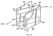
на фиг.5 - вид в перспективе пятого примера, частично открытой, предлагаемой в настоящем изобретении упаковки;figure 5 is a perspective view of a fifth example, partially open, proposed in the present invention packaging;
на фиг.6А - вид в плане пятого примера упаковки, открытой в одной конфигурации;on figa is a plan view of a fifth example of a package open in one configuration;
на фиг.6Б - вид в плане пятого примера упаковки, открытой в другой конфигурации;on figb is a plan view of a fifth example of packaging opened in a different configuration;
на фиг.7 - вид сзади пятой, частично открытой, упаковки;Fig.7 is a rear view of the fifth, partially open, packaging;
на фиг.8А-8В - виды в плане заготовок, используемых в пятом примере упаковки по фиг.5-7;on figa-8B - types in plan of the blanks used in the fifth example of packaging of Fig.5-7;
на фиг.9А-9В - виды заготовок по фиг.8, сложенные, как при использовании, в пятом примере упаковки;on figa-9B - types of blanks of Fig.8, folded, as in use, in the fifth example of packaging;
на фиг.10 - вид в перспективе шестого примера упаковки, частично открытой;figure 10 is a perspective view of a sixth example of packaging, partially open;
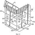
на фиг.11 - вид в плане шестого примера упаковки, открытой в одной конфигурации;11 is a plan view of a sixth example of a package open in one configuration;
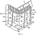
на фиг.12 - вид в плане шестого примера упаковки, открытой в другой конфигурации;12 is a plan view of a sixth example of a package opened in another configuration;
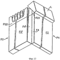
на фиг.13 - вид сзади шестого примера упаковки, частично открытой;13 is a rear view of a sixth example of a package partially open;
на фиг.14 - вид в плане заготовки, используемой в шестом примере упаковки;on Fig is a view in plan of the workpiece used in the sixth example of packaging;
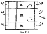
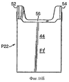
на фиг.15А-15В - виды в плане других заготовок, используемых в шестом примере упаковки;on figa-15B - types in plan of other blanks used in the sixth packaging example;
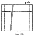
на фиг.16А-16В - виды заготовок по фиг.14 и 15, частично сложенных для использования в шестом примере упаковки;on figa-16B - types of blanks on fig.14 and 15, partially folded for use in the sixth packaging example;
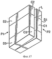
на фиг.17 - вид в перспективе седьмого примера упаковки;on Fig is a perspective view of a seventh example of packaging;
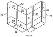
на фиг.18 - вид в плане седьмого примера упаковки, открытой в одной конфигурации;Fig. 18 is a plan view of a seventh example of a package open in one configuration;
на фиг.19 - вид в плане седьмого примера упаковки, открытой в другой конфигурации;Fig. 19 is a plan view of a seventh example of a package opened in a different configuration;
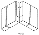
на фиг.20 - вид сзади седьмого примера упаковки, частично открытой;in Fig.20 is a rear view of a seventh example of a package partially open;
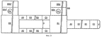
на фиг.21 - вид в плане заготовки, используемой в седьмом примере упаковки;on Fig is a view in plan of the workpiece used in the seventh example of packaging;
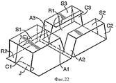
на фиг.22 - вид заготовки по фиг.21, сложенной, как при использовании в седьмом примере упаковки;in Fig.22 is a view of the blank of Fig.21, folded, as when used in the seventh example of packaging;
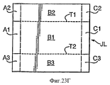
на фиг.23А-23Г - заготовки, используемые для создания первого варианта восьмого примера упаковки;on figa-23G - blanks used to create the first variant of the eighth example of packaging;
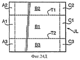
на фиг.24А-24Д - заготовки, используемые для создания второго варианта восьмого примера упаковки;on figa-24D - blanks used to create the second variant of the eighth example of packaging;
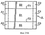
на фиг.25А-25В - заготовки, используемые для создания третьего варианта восьмого примера упаковки;on figa-25B - blanks used to create a third variant of the eighth example of packaging;
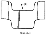
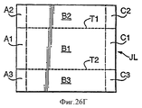
на фиг.26А-26Г - заготовки, используемые для создания четвертого варианта восьмого примера упаковки;on figa-26G - blanks used to create the fourth variant of the eighth example of packaging;
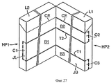
на фиг.27 - вид в перспективе девятого примера упаковки, в которой каждая пачка, входящая в упаковку, имеет шарнирно присоединенную крышку; иon Fig is a perspective view of a ninth example of the package, in which each pack included in the package has a hinged lid; and
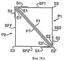
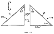
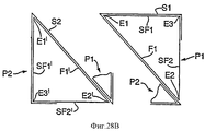
на фиг.28А-28В - схема расположения упаковки, в которой каждая пачка имеет треугольное поперечное сечение.on figa-28B is a layout diagram of the package, in which each bundle has a triangular cross section.
Общие положенияGeneral Provisions
Первый пример упаковки включает две пачки Р1 и Р2. В этом примере пачки представляют собой закрытые коробки, каждая из которых содержит сигареты. Две пачки объединены в схему расположения "лестница Якобса" (Jacobs ladder), которая позволяет каждой пачке вращаться вокруг другой, как показано на фиг.1Б и 1В. Таким образом, со ссылкой на фиг.1А и 1Б, предполагая, что пачка Р1 является стационарной, начиная с положения, показанного на фиг.1А, на котором грани (лицевые стороны) F1 и F1' двух пачек обращены одна к другой, пачка Р2 может вращаться вокруг края (ребра) Е2 пачки Р1 в направлении против часовой стрелки. Как показано на фиг.1В, пачка Р2 также может вращаться в направлении по часовой стрелке вокруг края Е1 пачки Р1. В одном из примеров любая из двух пачек может вращаться относительно другой из положения, показанного на фиг.1А на 180° до положения, параллельного граням F1 и F1', оставаясь обращенной в одном и том же направлении. В другом примере любая из двух пачек может перемещаться относительно другой из положения, показанного на фиг.1А на 360° до положения, параллельного граням F1 и F1', обращенным в противоположные направления: т.е. как показано на фиг.1А, но с Р2 слева от Р1. Эти и другие примеры будут описаны более подробно в следующем описании.The first packaging example includes two packs P1 and P2. In this example, the packs are closed boxes, each of which contains cigarettes. The two packs are combined into a Jacobs ladder layout that allows each pack to rotate around the other, as shown in FIGS. 1B and 1B. Thus, with reference to FIGS. 1A and 1B, assuming that the packet P1 is stationary, starting from the position shown in FIG. 1A, on which the faces (front sides) F1 and F1 'of the two packets are facing one another, the packet P2 can rotate around the edge (ribs) E2 of the packet P1 in a counterclockwise direction. As shown in FIG. 1B, the packet P2 can also rotate in a clockwise direction around the edge E1 of the packet P1. In one example, either of the two packs can rotate relative to the other from the position shown in FIG. 1A by 180 ° to a position parallel to the faces F1 and F1 ', while remaining facing in the same direction. In another example, either of the two packs can move relative to the other from the position shown in FIG. 1A 360 ° to a position parallel to the faces F1 and F1 'facing in opposite directions: i.e. as shown in FIG. 1A, but with P2 to the left of P1. These and other examples will be described in more detail in the following description.
Первый примерFirst example
Со ссылкой на фиг.1А, в первом примере две пачки Р1 и Р2 соединены по меньшей мере двумя полосками S1 и S2 (материала). В следующем описании исходно предполагается, что имеются две полоски. Пачка Р1 имеет прямоугольное поперечное сечение с основанием, передней гранью F1, задней гранью F2 и боковыми гранями (сторонами) F3 и F4, выходящими из основания. Грани F1 и F3 имеют общий край Е1; грани F1 и F4 имеют общий край Е2; грани F2 и F3 имеют общий край Е3; и грани F2 и F4 имеют общий край Е4. Пачка Р2 идентична по граням и краям, обозначенными аналогичными ссылочными номерами, что и у пачки Р1, но с надстрочным штрихом. Края с E1 по Е4 и Е1' по Е4' выходят из оснований пачек. Полоска S1 прикреплена (зафиксирована) к пачке Р1 на грани F3 и свободно проходит вокруг края Е1, между и поперек граней F1 и F1' до края Е2' пачки Р2 и вокруг края Е2' пачки Р2 и, далее, закреплена на грани F4' пачки Р2. Полоска S2 прикреплена к пачке Р1 на грани F4 и свободно проходит вокруг края Е2, между и поперек граней F1 и F1' до края Е1' пачки Р2 и вокруг края Е1' пачки Р2 и прикреплена на грани F3' пачки Р2.With reference to FIG. 1A, in the first example, two bundles P1 and P2 are connected by at least two strips S1 and S2 (material). In the following description, it is initially assumed that there are two strips. Member P1 has a rectangular cross-section with a base, a front face F1, a back face F2 and side faces (sides) F3 and F4 extending from the base. Facets F1 and F3 have a common edge E1; faces F1 and F4 have a common edge E2; faces F2 and F3 have a common edge E3; and faces F2 and F4 have a common edge E4. Member P2 is identical in terms of faces and edges denoted by the same reference numbers as in member P1, but with a superscript line. Edges E1 through E4 and E1 'through E4' extend from the base of the packs. The strip S1 is attached (fixed) to the bundle P1 on the edge F3 and freely passes around the edge E1, between and across the faces F1 and F1 'to the edge E2' of the bundle P2 and around the edge E2 'of the bundle P2 and, further, is fixed on the edge F4' of the bundle P2. The strip S2 is attached to the packet P1 on the edge F4 and freely passes around the edge E2, between and across the faces F1 and F1 'to the edge E1' of the packet P2 and around the edge E1 'of the packet P2 and is attached to the edge F3' of the packet P2.
Как показано на фиг.1Б, это позволяет пачке Р2 вращаться вокруг края Е2 пачки PI в направлении против часовой стрелки. В положении, показанном на фиг.1А, полоски SI и S2 проходят в диагонально противоположных направлениях между двумя пачками, причем полоски пересекаются по центру между двумя пачками. По мере вращения пачки Р2 против часовой стрелки вокруг края Е2, точка пересечения перемещается к Е2. Вращение прекращается, когда грани F4 и F4' обращены друг к другу. Как показано на фиг.1В, пачка Р2 может вращаться аналогичным образом вокруг края Е1 в направлении по часовой стрелке, пока грани F3 и F3' не соприкоснутся друг с другом.As shown in FIG. 1B, this allows the burst P2 to rotate around the edge E2 of the burst PI in a counterclockwise direction. In the position shown in FIG. 1A, the strips SI and S2 extend in diagonally opposite directions between the two bundles, the strips intersecting in the center between the two bundles. As the pack P2 rotates counterclockwise around the edge of E2, the intersection point moves to E2. The rotation stops when the faces F4 and F4 'are facing each other. As shown in FIG. 1B, the bundle P2 can rotate in a similar manner around the edge E1 in a clockwise direction until the faces F3 and F3 ′ are in contact with each other.
Нужны минимум две полоски. Однако могут быть предусмотрены три полоски, с полоской S1 между другими двумя полосками S2 и S3, как показано в дополнительных примерах, описанных далее.You need at least two strips. However, three strips may be provided, with stripe S1 between the other two strips S2 and S3, as shown in the further examples described below.
Полоски (ленты) могут быть выполнены из любого тонкого гибкого материала. Если используются только две полоски, то используемый материал является жестким в поперечном направлении относительно длинного направления полосок. Может быть предусмотрено больше трех полосок.Strips (tapes) can be made of any thin flexible material. If only two strips are used, then the material used is stiff in the transverse direction relative to the long direction of the strips. More than three strips may be provided.
Как описано далее, полоски имеют две стороны и, по меньшей мере, части В1 и В2 полосок видны в различном положении полосок и могут быть использованы для цифровой индикации и/или графики.As described below, the strips have two sides and at least portions B1 and B2 of the strips are visible at different positions of the strips and can be used for digital display and / or graphics.
Заготовка и второй примерHarvesting and second example
На фиг.2А и Б показана заготовка материала, который можно использовать для соединения двух пачек Р1 и Р2, используя три полоски S1-S3 такого материала в схеме расположения в виде "лестница Якобса" во втором примере настоящего изобретения. На фиг.2А показана заготовка перед использованием. На фиг.2Б показана заготовка, сложенная в конфигурации ее использования. Заготовка в основном прямоугольная. Полоска S1 находится, в этом примере, между полосками S2 и S3 и она шире, чем каждая из двух других полосок. Полоска S1 включает клапаны А1 и С1, которые при использовании прикреплены к грани F3 пачки Р1 и грани F4' пачки Р2, соответственно, и зону B1, которая проходит от грани F3 свободно поперек граней F1 и F1' до грани F4'. Полоска S2 содержит клапаны С2 и А2, которые при использовании прикреплены к грани F4 пачки Р1 и грани F3' пачки Р2, соответственно, и зону B2, которая проходит от грани F4 свободно между гранью F1 и F1', до грани F3. Аналогично, полоска S3 содержит клапаны С3 и A3, которые при использовании прикреплены к грани F4 пачки Р1 и грани F3' пачки Р2, соответственно, и зону B3, которая проходит от грани F4, свободно поперек граней F1 и F1', до грани F3'. Клапаны А1 и А2 разделены разрезом X'. Клапаны А1 и A3 разделены разрезом Х2. Аналогично, клапан С1 отделен от С2 и С3 разрезами Х3 и Х4. Зона В1 присоединена в заготовке к зонам В2 и В3 перфорированными линиями разрыва Т1 и Т2. Клапаны А1-A3 и С1-С3 присоединены к зонам В1-В3. В некоторых вариантах, как при использовании картона или бумаги, клапаны присоединены к зонам линиями сгиба L1 и L2. В других вариантах, таких как пленка, нет линий сгиба.On figa and B shows the procurement of material that can be used to connect two packs of P1 and P2, using three strips S1-S3 of such material in the layout in the form of a "Jacobs ladder" in the second example of the present invention. On figa shows the workpiece before use. On figb shows the workpiece folded in the configuration of its use. The workpiece is mostly rectangular. The strip S1 is, in this example, between the strips S2 and S3 and it is wider than each of the other two strips. Strip S1 includes valves A1 and C1, which when used are attached to face F3 of member P1 and face F4 'of member P2, respectively, and zone B1, which runs from face F3 freely across faces F1 and F1' to face F4 '. Strip S2 contains valves C2 and A2, which, when used, are attached to face F4 of member P1 and face F3 'of member P2, respectively, and zone B2, which extends from face F4 freely between face F1 and F1', to face F3. Similarly, strip S3 contains valves C3 and A3, which when used are attached to face F4 of member P1 and face F3 'of member P2, respectively, and zone B3, which extends from face F4, freely across faces F1 and F1', to face F3 ' . Valves A1 and A2 are separated by a cut X '. Valves A1 and A3 are separated by section X2. Similarly, valve C1 is separated from C2 and C3 by cuts X3 and X4. Zone B1 is attached in the blank to zones B2 and B3 with perforated break lines T1 and T2. Valves A1-A3 and C1-C3 are connected to zones B1-B3. In some embodiments, as with cardboard or paper, the flaps are attached to the zones by fold lines L1 and L2. In other embodiments, such as film, there are no fold lines.
Со ссылкой на фиг.2В, заготовка, при использовании, прикреплена одной частью к двум пачкам Р1 и Р2 с клапанами А1-А3 и С1-С3 адгезивом (например, клеем или термосваркой) к краям пачки, как описано выше. Следует учесть, что, если фиг.1 считать видом сверху, то фиг.2В - это общий вид снизу (или наоборот).With reference to FIG. 2B, the preform, when used, is attached in one piece to two packs P1 and P2 with valves A1-A3 and C1-C3 with adhesive (e.g., glue or heat seal) to the edges of the pack, as described above. It should be noted that, if Fig. 1 is considered a top view, then Fig. 2B is a general view from below (or vice versa).
Чтобы открыть упаковку, пользователь поворачивает одну пачку относительно другой. При этом разрывается перфорация вдоль линий разрыва Т1 и Т2.To open the package, the user rotates one pack relative to another. In this case, perforation is broken along the lines of discontinuity T1 and T2.
Третий пример и заготовкаThird Example and Procurement
Как показано на фиг.1 штриховыми линиями, и на фиг.2Г и 2Д, клапаны А1-A3 и С1-С3 могут быть удлинены, как указано А1'-A3' и С1'-С3', чтобы они проходили свободно поперек граней F3, F4, F3' и F4' и были прикреплены к граням F2 и F2'. Это позволяет одну из двух пачек вращать на 360° относительно другой. В другом варианте клапаны А1-A3 и С1-С3 прикреплены к боковым сторонам (граням) пачек, как показано на фиг.2А и 2Б и А1' удлиненные части А1'-A3' и С1'-С3' приклеены.As shown in Fig. 1 by dashed lines, and in Figs. 2G and 2D, the valves A1-A3 and C1-C3 can be extended as indicated by A1'-A3 'and C1'-C3' so that they extend freely across the faces F3 , F4, F3 'and F4' and were attached to faces F2 and F2 '. This allows one of the two packs to rotate 360 ° relative to the other. In another embodiment, valves A1-A3 and C1-C3 are attached to the sides (faces) of the packs, as shown in FIGS. 2A and 2B and A1 ', the elongated parts A1'-A3' and C1'-C3 'are glued.
Четвертый пример и заготовкаFourth Example and Procurement
Как показано на фиг.3А и Б, и на фиг.1Б, по меньшей мере одна из удлиненных частей С1'-С3' может проходить по всей грани F2' пачки Р2. В некоторых вариантах клапаны A1, А2 и A3 прикреплены адгезивом к боковым граням F4', F4 и F4, соответственно, пачки Р2 и Р1, удлиненные части С1', С2' и С3' приклеены, в других вариантах удлиненные части С1', С2' и С3' прикреплены адгезивом к граням F2', F2 и F2, соответственно, клапаны C1, С2 и С3 не прикреплены адгезивом к боковым граням F4', F4 и F4. Любая одна или несколько удлиненных частей С1', С2' и С3' могут нести цифровую индикацию и/или графику на одной или обеих сторонах.As shown in FIGS. 3A and B, and in FIG. 1B, at least one of the elongated parts C1'-C3 'may extend along the entire face F2' of the burst P2. In some embodiments, valves A1, A2 and A3 are attached with adhesive to the side faces F4 ', F4 and F4, respectively, packs P2 and P1, elongated parts C1', C2 'and C3' are glued, in other embodiments, elongated parts C1 ', C2' and C3 'are attached by adhesive to faces F2', F2 and F2, respectively, valves C1, C2 and C3 are not attached by adhesive to side faces F4 ', F4 and F4. Any one or more elongated parts C1 ', C2' and C3 'may carry digital indications and / or graphics on one or both sides.
Удлиненные части С1', С2' и С3' могут быть свободными.The elongated parts C1 ', C2' and C3 'may be free.
Варианты с первого по четвертый примеров
Пачки Р1 и Р2 могут быть обернуты в пластиковую обертку, например, целлофан, полипропилен или другой пригодный материал. Заготовка по фиг.2 или 3 может также быть из такого пластмассового материала, прикрепленного к обертке пачек из пластмассы.The packs P1 and P2 can be wrapped in a plastic wrap, for example, cellophane, polypropylene or other suitable material. The blank of FIG. 2 or 3 may also be of such a plastic material attached to a wrapper of plastic packs.
Пачки могут быть из картона, как обычно в этой области, и заготовка по фиг.2 или 3 может быть из картона или бумаги, прикрепленной к картону пачек. В результате комбинированная упаковка может быть обернута в обертку из пластмассы. Вместо того, чтобы составлять неотъемлемую часть заготовки, полоски могут быть отделены изначально.The bundles may be made of cardboard, as is usual in this area, and the blank of FIGS. 2 or 3 may be made of cardboard or paper attached to the cardboard of the bundles. As a result, the combination package can be wrapped in a plastic wrap. Instead of being an integral part of the workpiece, the strips can be separated initially.
Способ изготовления упаковки - фиг.4А и 4Б.A method of manufacturing a package - figa and 4B.
Упаковка, описанная выше со ссылкой на фиг.1, 2А, 2Б и 2В, может быть изготовлена следующим способом.The packaging described above with reference to FIGS. 1, 2A, 2B and 2B can be made in the following manner.
Пачки Р1 подаются соответствующим конвейером на станцию, на которой соединительная заготовка JL прикладывает к каждой пачке Р1 (этап ST1). В этом примере заготовки JL отрезают от рулона материала. В другом примере заготовки JL отрезают заранее и хранят в накопителе. Они подаются из накопителя и прикладываются к пачкам. Перфорация и разрезы могут быть получены заранее в рулоне материала или создана на станции из ровного материала. В этом примере заготовка JL прикрепляется адгезивом к переднему краю пачки с адгезивным присоединением клапанов С3 и С2 наружных полосок S3 и S2 к пачке Р1. Заготовку JL затем отрезают (этап ST2). Первые пачки Р1 с присоединенными к ним адгезивом заготовками JL передаются по конвейеру на станцию, на которой подают вторые пачки Р2 (этап ST3) и размещают на заготовке JL (этап ST4). На фиг.4А вторые пачки Р2 подаются на первые пачки Р1 с одной стороны конвейера. На фиг.4Б вторые пачки Р2 подают на этапе ST3' и размещают поверх первых пачек Р1 (этап ST4'). На следующих этапах за ST4 (или ST4') по ST8 заготовка JL присоединяется адгезивом к первым Р1 и вторым пачкам Р2, чтобы соединить их в схеме расположения типа "лестница Якобса".Packs P1 are fed by a suitable conveyor to a station at which a connecting preform JL is applied to each packet P1 (step ST1). In this example, JL blanks are cut from a roll of material. In another example, JL blanks are cut in advance and stored in a drive. They are fed from the drive and applied to the bundles. Perforations and cuts can be obtained in advance in a roll of material or created at the station from flat material. In this example, the preform JL is attached with adhesive to the front edge of the packet with adhesive attachment of valves C3 and C2 of the outer strips S3 and S2 to the packet P1. The blank JL is then cut off (step ST2). The first packs P1 with the adhesive blanks JL attached to them are conveyed to the station where the second packs P2 are fed (step ST3) and placed on the blank JL (step ST4). In FIG. 4A, the second bursts P2 are fed to the first bursts P1 on one side of the conveyor. In FIG. 4B, the second bursts P2 are supplied in step ST3 ′ and placed on top of the first bursts P1 (step ST4 ′). In the following steps, beyond ST4 (or ST4 ') to ST8, the blank JL is attached with adhesive to the first P1 and second packs of P2 to connect them in a Jacobs staircase layout.
На этапе ST4 и ST4' две пачки Р1 и Р2 с заготовкой JL между ними совмещают, т.е. транспортируют и аккуратно выравнивают.At step ST4 and ST4 ', the two packs P1 and P2 with the workpiece JL are combined between them, i.e. transported and neatly aligned.
В примере, показанном на этапах ST5 и ST6, две пачки Р1 и Р2 перемещают вертикально вниз через направляющие или через ротационный механизм, который отгибает клапаны C1, А2 и A3 вверх и на этапе ST7 панели нагревателя присоединяют адгезивом клапаны C1, А2 и A3 к пачкам, на этапе ST8 пачки перемещают вертикально вверх через направляющие, которые отгибают оставшийся клапан А1 вниз, и на этапе ST9 клапан А1 присоединяется адгезивом к упаковке посредством панели нагревателя.In the example shown in steps ST5 and ST6, the two packs P1 and P2 are moved vertically downward through the guides or through the rotary mechanism, which bends valves C1, A2 and A3 upward and, in step ST7, the heater panels attach adhesive valves C1, A2 and A3 to the packs , at step ST8, the packs are moved vertically upward through the guides that fold the remaining valve A1 downward, and at step ST9, the valve A1 is attached to the package with adhesive via the heater panel.
В альтернативном варианте этапы с ST5 по ST9 могут быть скомбинированы, при этом вертикальное перемещение вызывает одновременное отгибание клапанов A1, А2, A3 и С1 в нужном направлении и присоединение адгезивом к упаковке посредством панели нагревателя.Alternatively, steps ST5 to ST9 can be combined, with vertical movement causing the flaps A1, A2, A3 and C1 to be folded in the right direction at the same time and adhesive to be attached to the package via the heater panel.
Пятый пример - фиг.5-9Fifth Example - FIGS. 5-9
Со ссылкой на фиг.5, 8Б, 8С и 9А и 9В, две пачки Р1 и Р2 каждая содержат внутреннюю оболочку (корпус) I (фиг.8В и 9В) и наружную оболочку (корпус) О (фиг.8Б и 9А). Наружная оболочка представляет собой трубу прямоугольного сечения с передней и задней большими гранями 2 и 4 и меньшими боковыми гранями 6 и 8. Внутренняя оболочка содержит заднюю стенку 10, боковые клапаны 12 и 14, верхний и нижний 16 и 18, шарнирно (с возможностью поворота) прикрепленные к задней стенке 10, и язычки 20 и 22, шарнирно прикрепленные к клапанам 16 и 18. Внутренняя оболочка объединена с наружной для размещения сигарет. В показанном примере каждая пачка P1, Р2 содержит один ряд сигарет, но в других вариантах может содержать более одного ряда. Могут быть использованы другие формы пачки Р1 и Р2, известные специалистам. Например, каждая пачка Р1 и Р2 может быть пачкой, состоящей из одной части.With reference to FIGS. 5, 8B, 8C and 9A and 9B, two packs P1 and P2 each contain an inner shell (case) I (FIGS. 8B and 9B) and an outer shell (case) O (FIG. 8B and 9A). The outer shell is a pipe of rectangular cross section with the front and rear
Две пачки Р1 и Р2 соединены в схеме расположения "лестница Якобса" посредством конструкции, показанной на фиг.9Б в собранном виде, и на фиг.8А в виде заготовки. Эта конструкция содержит стенки R1 и R2, между которыми проходят полоски S2 и S3. Полоски S2 и S3 имеют промежуток между ними, т.е. разделены на заранее определенное расстояние D. Полоски S2 и S3 содержат зоны В2 и В3, присоединенные к стенке R1 секциями С2 и С3 и присоединенные к стенке R2 секциями А2 и A3. Стенки R1 и R2 и полоски S2 и S3 образуют прямоугольное отверстие шириной D. Полоска S1 проходит от центра боковой стороны стенки R1 на удалении от отверстия. Полоска S1 имеет ширину, равную или меньше D. Полоска S1 содержит зону В1, присоединенную к стенке R1 секцией А1. Соединительный язычок J присоединен к зоне В1 посредством секции С1. Зона В1 проходит через отверстие между полосками S2 и S3, а соединительный язычок J приклеен к границе грани R2 на удалении от отверстия, чтобы создавать конструкцию в форме восьмерки, как показано на фиг.9Б. Эта конструкция имеет две, содержащие пачки части: одна определена стенкой R2, секцией полосок C1, А2 и A3 и зонами B1, В2 и В3; другая - стенкой R1, секциями полосок С2, С3, А1, и зонами B1, В2 и В3. Каждая содержащая пачку часть образует пачку, как показано на фиг.5-7. На фиг.5 и 7 показаны собранные пачки при просмотре в направлении стрелки, помеченной "(фиг.5А), (фиг.7)" на фиг.9Б. На фиг.6А и 6Б показаны пачки Р1 и Р2 в различных положениях. На фиг.6А и 6Б видно, что полоска S2 захватывает язычок пачки Р1 с левой стороны на фиг.6А и Р2 на фиг.6Б. Доступ обеспечен к пачке с правой стороны; доступ к пачке с левой стороны возможен при ее вращении вокруг другой пачки, чтобы перевести ее на правую сторону. Безусловно, пачки могут быть скомпонованы таким образом, что пачка с левой стороны обеспечивает доступ к сигаретам.Two packs P1 and P2 are connected in a Jacobs staircase layout using the assembly shown in FIG. 9B and FIG. 8A as a blank. This structure contains walls R1 and R2, between which strips S2 and S3 pass. Strips S2 and S3 have a gap between them, i.e. divided by a predetermined distance D. Strips S2 and S3 contain zones B2 and B3 attached to the wall R1 by sections C2 and C3 and attached to the wall R2 by sections A2 and A3. The walls R1 and R2 and the strips S2 and S3 form a rectangular hole of a width D. The strip S1 extends from the center of the side of the wall R1 at a distance from the hole. Strip S1 has a width equal to or less than D. Strip S1 contains zone B1 connected to wall R1 by section A1. The connecting tab J is attached to zone B1 via section C1. Zone B1 passes through the hole between strips S2 and S3, and the connecting tab J is glued to the boundary of the edge R2 away from the hole to create a figure-eight structure, as shown in FIG. 9B. This design has two parts containing bundles: one is defined by wall R2, a section of strips C1, A2 and A3 and zones B1, B2 and B3; the other by the wall R1, sections of strips C2, C3, A1, and zones B1, B2 and B3. Each portion containing the packet forms a packet, as shown in FIGS. 5-7. Figures 5 and 7 show assembled packs when viewed in the direction of the arrow marked "(Fig. 5A), (Fig. 7)" in Fig. 9B. On figa and 6B shows the packs P1 and P2 in various positions. On figa and 6B it is seen that the strip S2 captures the tongue of the pack P1 on the left side in figa and P2 in fig.6B. Access is provided to the pack on the right side; access to the packet from the left side is possible when it is rotated around another packet to transfer it to the right side. Of course, the packs can be arranged in such a way that the pack on the left side provides access to cigarettes.
В варианте, в котором используются пачки "пенального типа" ("side and shell"), полоски не должны захватывать клапаны, поскольку пенал позволяет выдвинуть внутреннюю часть из наружной оболочки, чтобы получить доступ к сигаретам.In an embodiment that uses “side and shell” packs, the strips should not catch the valves, since the pencil case allows the inner part to be pulled out of the outer shell to gain access to cigarettes.
В этом пятом примере все заготовки по фиг.8А-8В изготовлены из картона, известного специалистам. Заготовки могут быть из любого другого пригодного материала, например пластмассы. В одном варианте наружные оболочки пачки Р1 и Р2 приклеены к конструкции "лестница Якобса". В другом варианте пачки свободно двигаются внутри этой конструкции.In this fifth example, all the blanks of FIGS. 8A-8B are made of cardboard known to those skilled in the art. The blanks may be of any other suitable material, for example plastic. In one embodiment, the outer shells of the bundle P1 and P2 are glued to the Jacobs staircase. In another embodiment, the packs move freely within this structure.
Хотя заготовка по фиг.8А в основном прямоугольная и имеет прямоугольную полоску S1 шириной D1, которая проходит через соответствующее прямоугольное отверстие шириной D, заготовки 8С необязательно должны быть прямоугольными. Полоска S1 может иметь периферийную часть любой формы. Отверстие может иметь периферию любой формы. Максимальная ширина полоски должна быть равна или меньше, чем минимальная ширина отверстия, чтобы позволить полоске S1 проходить через это отверстие. Полоска S1 и отверстие необязательно центрированы по оси заготовки.Although the blank of FIG. 8A is substantially rectangular and has a rectangular strip S1 of width D1 that passes through a corresponding rectangular hole of width D, blanks 8C need not be rectangular. Strip S1 may have a peripheral part of any shape. The hole may have a periphery of any shape. The maximum width of the strip must be equal to or less than the minimum width of the hole to allow strip S1 to pass through this hole. The strip S1 and the hole are optionally centered on the axis of the workpiece.
Шестой пример - фиг.10-16Sixth Example — FIGS. 10-16
В шестом примере представлена упаковка, которая содержит две пачки Р1 и Р2, соединенные в схеме расположения "лестница Якобса", причем эти две пачки имеют одну шарнирно присоединенную крышку. Как показано на фиг.10-13, две пачки Р1 и Р2 соединены вместе заготовкой, как показано на фиг.2 и описано со ссылкой, например, на фиг.2. Крышка L, шарнирно прикрепленная к одной из пачек (Р1), закрывает верх обеих пачек Р1 и Р2.In a sixth example, a package is presented that contains two packs P1 and P2 connected in a Jacobs staircase arrangement, these two packs having one hinged lid. As shown in FIGS. 10-13, two packs P1 and P2 are joined together by the blank, as shown in FIG. 2 and described with reference, for example, to FIG. 2. A lid pivotally attached to one of the packs (P1) covers the top of both packs P1 and P2.
На фиг.14, 15 и 16 показаны заготовки, которые используются для создания упаковки. На фиг.15А показан вид в плане соединительной заготовки JL, используемой для соединения двух пачек вместе. Соединительная заготовка JL идентична заготовке, описанной со ссылкой на фиг.2. Заготовки на фиг.14-16 представляют собой модификацию заготовок, описанных в публикации WO 2004/080844, содержание которой включено в настоящий документ в качестве ссылки.On Fig, 15 and 16 shows the blanks that are used to create the package. On figa shows a view in plan of the connecting workpiece JL used to connect the two packs together. The joint preform JL is identical to the preform described with reference to FIG. 2. The blanks of FIGS. 14-16 are a modification of the blanks described in WO 2004/080844, the contents of which are incorporated herein by reference.
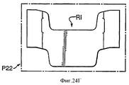
Пачка Р1 содержит две части: часть P11, показанную на фиг.14; и часть Р12, показанную на фиг.15Б. Пачка Р2 содержит две части: часть Р21, показанную на фиг.14; и часть Р22, показанную на фиг.15В. На фиг.15Б и В показано положение соединительной заготовки JL по отношению к заготовкам Р12 и Р22, которые образуют части пачек Р1 и Р2.The packet P1 contains two parts: the part P11 shown in Fig.14; and a portion P12 shown in FIG. 15B. Pack P2 contains two parts: part P21, shown in Fig.14; and a portion P22 shown in FIG. 15B. On figb and C shows the position of the connecting blanks JL with respect to the blanks P12 and P22, which form part of the packs P1 and P2.
Части Р11 и Р21 представляют собой части цельной заготовки BL, которая также содержит крышку L. Часть 21 содержит основную грань F2' и грани F3' и F4'. Часть Р21 присоединена к части Р11 клапанами 78 и 80, соответственно, составляющими с ними единое целое. Клапаны 78 и 80 соединены между собой линией разрыва Т3.Parts P11 and P21 are parts of a one-piece blank BL, which also includes a lid L. Part 21 contains a main face F2 'and faces F3' and F4 '. Part P21 is connected to part P11 by
Часть Р11 содержит основную грань F2 и грани F3 и F4.Part P11 contains the main face F2 and faces F3 and F4.
Часть P11 присоединена к крышке L посредством линии сгиба 82, которая имеет дополнительное понижение прочности, как указано ссылочным номером 82'. Такая форма крышки известна; см., например WO 2004/080844.Part P11 is attached to the lid L via a
Крышка L содержит заднюю стенку 84, внутренние боковые стенки 74 и 76, верхнюю стенку 68 и переднюю стенку 62. Клапан 60 обеспечивает усиление для передней стенки, а клапаны 70 и 72 соединяют боковые стенки 74 и 76 с верхней стенкой. Крышка дополнительно содержит наружные боковые стенки 64 и 66, которые усилены посредством внутренних боковых стенок 74 и 76. Линии сгиба между клапанами и стенками указаны штриховыми линиями на фиг.14.The cover L comprises a
Часть Р12 представляет собой внутреннюю часть, имеющую наружную грань 30, которая соответствует грани F1. Наружная грань 30 соединена нижней стенкой 36 с внутренней задней стенкой 38. Грань 30 имеет боковые клапаны 32 и 34. Задняя стенка 38 имеет боковые клапаны 40 и 42.Part P12 is an inner part having an
Часть Р22 представляет собой другую внутреннюю часть, имеющую грань 44, которая соответствует грани F1' и задней стенке 56. Задняя стенка 56 соединена с гранью 44 нижней стенкой 50. Стенка 56 имеет боковые клапаны 52 и 54. Грань 44 имеет боковые клапаны 46 и 48.Part P22 is another inner part having a
На фиг.15Б и 16В показано, что внутренняя часть Р22 собрана посредством сгиба боковых клапанов 46, 48, 52 и 54 под прямым углом к грани 44 и стенке 56 вдоль линий сгиба, указанных штриховыми линиями на фиг.15В. Грань 44 и стенка 56 согнуты под прямым углом к нижней стенке 50 вдоль линий сгиба, указанных на фиг.15В. Боковые клапаны 46 и 52 приклеены друг к другу. Боковые клапаны 48 и 54 приклеены друг к другу. Получаемая в результате коробка показана на фиг.16Б.FIGS. 15B and 16B show that the inner part P22 is assembled by folding the side flaps 46, 48, 52, and 54 at right angles to the
На фиг.15Б и 16В показано, что внутренняя часть Р12 собрана путем сгибания боковых клапанов 32, 34, 40 и 42 под прямым углом к грани 30 и стенке 38 вдоль линий сгиба, указанных штриховыми линиями на фиг.15Б. Грань 30 и стенка 38 согнуты под прямым углом к нижней стенке 36 вдоль линий сгиба, указанных на фиг.15Б. Боковые клапаны 40 и 34 приклеены друг к другу. И боковые клапаны 32 и 42 приклеены друг к другу. Получаемая в результате коробка показана на фиг.16В.On figb and 16B shows that the inner part P12 is assembled by folding the side flaps 32, 34, 40 and 42 at right angles to the
Соединительная заготовка JL расположена, как показано на фиг.15Б и В относительно граней F1 и F1' на внутренних частях Р12 и Р22. Клапаны А2 и A3 соединительной заготовки прикреплены к боковому клапану 32 внутренней части Р12. Клапан С1 соединительной заготовки прикреплен к боковому клапану 34 внутренней части Р12. Клапаны С2 и С3 соединительной заготовки прикреплены к боковому клапану 48 внутренней части Р22. Клапан А1 соединительной заготовки JL прикреплен к боковому клапану 46 внутренней части Р22. Затем, задняя внутренняя стенка части Р22 прикреплена на грани F2' заготовки BL (фиг.14) с нижней стенкой 50 на секции нижней стенки 78. Боковые клапаны F3' и F4' заготовки BL приклеены к боковым клапанам внутренней части Р22. Задняя внутренняя стенка 38 части Р12 прикреплена на грани F2 заготовки BL с нижней стенкой 36 на секции нижней стенки 80. Боковые клапаны F3 и F4 заготовки BL приклеены к боковым клапанам 32 и 34 внутренней части Р12. Грани 44 и 30 внутренних частей Р22 и Р12, соответственно, образуют грани F1 и F1' пачки.The connecting blank JL is located, as shown in figv and C relative to the faces F1 and F1 'on the inner parts P12 and P22. Valves A2 and A3 of the connecting piece are attached to the
В альтернативном варианте соединительная заготовка JL может быть присоединена непосредственно к боковым клапанам F3, F3', F4 и F4' основной заготовки BL. Внутренние части Р12 и Р22 в собранном виде могут сдвигаться между гранью F2 и соединительной заготовкой JL и гранью F2' и соединительной заготовкой JL, соответственно. Внутренние части Р12 и Р22 останавливаются напротив нижних панелей 80 и 78, соответственно. В этой схеме расположения приклеивание внутренних частей Р12 и Р22 непосредственно к основной заготовке BL и/или соединительной заготовке JL не является обязательным.Alternatively, the connecting blank JL may be attached directly to the side flaps F3, F3 ′, F4 and F4 ′ of the main blank BL. The assembled internal parts P12 and P22 can be shifted between the face F2 and the joint blank JL and the face F2 'and the joint blank JL, respectively. The interior parts P12 and P22 stop opposite the
Крышка L образована сгибанием внутренних боковых стенок 74 и 76 вместе с клапанами 70 и 72 под прямым углом к задней стенке 84 относительно линии сгиба у боковых сторон задней стенки. Клапаны 70 и 72 отгибаются вовнутрь под прямым углом к внутренним задним стенкам 74 и 76. Усиливающий клапан 60 отгибается вовнутрь от передней стенки 62 и прикреплен к ней. Верхняя стенка 68 отгибается относительно линии сгиба между ней и задней стенкой 84 на клапаны 70 и 72 и, в этом примере, прикреплена к клапанам 70 и 72. В другом примере клапаны 70 и 72 остаются свободными. Передняя стенка 62 отгибается вниз под прямым углом к верхней стенке. Наружные боковые стенки 64 и 66 отгибаются и прикрепляются к внутренним боковым стенкам 74 и 76.Cover L is formed by bending the
Со ссылкой на фиг.10, собранная, но неоткрытая упаковка содержит пачки Р1 и Р2, соединенные секциями боковых стенок 78 и 80 с неповрежденной линией разрыва Т3. Кроме того, полоска S1 соединена с полосками S2 и S3 с неповрежденными линиями разрыва Т1 и Т2. Упаковка открывается путем открывания крышки L и вращения пачки Р2 относительно пачки Р1, отделяя секции нижних стенок 78 и 80 вдоль линии разрыва Т3 и отделяя полоску S1 от полосок S2 и S3 вдоль линий разрыва Т1 и Т2.With reference to FIG. 10, the assembled but unopened package contains bundles P1 and P2 connected by sections of the
На фиг.16А показан другой вариант этого примера, где часть Р21 исходно отделена от части P11, т.е. заготовка BL заменена двумя заготовками, фактически отделенными вдоль линии разрыва Т3.On figa shows another variant of this example, where part P21 is initially separated from part P11, i.e. the blank BL is replaced by two blanks that are actually separated along the tear line T3.
В еще одном варианте линия разрыва Т3 остается неповрежденной при создании и прорезается машиной, т.е. линия Т3 разрезается в режиме "онлайн". Пачка, поставляемая потребителю, имеет отдельные части Р11 и Р21.In yet another embodiment, the tear line T3 remains intact upon creation and is cut by the machine, i.e. T3 line is cut online. The pack delivered to the consumer has separate parts P11 and P21.
Соединительная заготовка имеет такой размер и расположена таким образом, чтобы крышку L можно было открыть без повреждения полосок соединительной заготовки.The connecting preform is sized and arranged so that the lid L can be opened without damaging the strips of the connecting preform.
Способ изготовления упаковки по фиг.10-16A method of manufacturing a package of figure 10-16
Шестой пример может быть изготовлен следующим образом. Две пачки Р1 и Р2 могут быть соединены по схеме расположения "лестница Якобса", как описано со ссылкой на фиг.4. Заготовка по фиг.14 отгибается вокруг соединенных пачек Р1 и Р2.The sixth example can be made as follows. Two packs P1 and P2 can be connected in a Jacobs staircase arrangement, as described with reference to FIG. 4. The blank of FIG. 14 is folded around connected bundles P1 and P2.
Седьмой пример и заготовки - Фиг.17-22Seventh example and blanks - Fig.17-22
Седьмой пример и его заготовки являются вариантом пятого примера по Фиг.4-9. Седьмой пример отличается от пятого примера, главным образом, тем, что он предполагает соединение двух обычных пачек с шарнирно прикрепленными крышками Р1 и Р2, которые могут быть обернуты в пластиковую обертку.The seventh example and its preforms are a variation of the fifth example of FIGS. 4-9. The seventh example differs from the fifth example, mainly in that it involves joining two ordinary packs with pivotally attached caps P1 and P2, which can be wrapped in a plastic wrap.
Две пачки Р1 и Р2 соединены в схеме расположения "лестница Якобса" посредством конструкции, показанной на фиг.22 в собранном виде и на фиг.21 в виде заготовки. Эта конструкция содержит стенки R1 и R2, между которыми проходят полоски S2 и S3. Полоски S2 и S3 имеют промежуток между ними, т.е. разделены на заранее определенное расстояние D. Полоски S2 и S3 содержат зоны В2 и В3, присоединенные к стенке R1 секциями С2 и С3 и к стенке R2 секциями А2 и A3. Стенки R1 и R2 и полоски S2 и S3 образуют прямоугольное отверстие ширины D. Полоска S1 проходит от центра боковой стороны стенки R1 на удалении от отверстия. Полоска S1 имеет ширину, равную или меньше D. Полоска S1 содержит зону В1, присоединенную к стенке R1 секцией А1. Соединительный язычок J присоединен к зоне В1 посредством секции С1. Зона В1 проходит через отверстие между полосками S2 и S3, и соединительный язычок J приклеен к границе грани R2 на удалении от отверстия, чтобы создавать конструкцию в форме восьмерки, как показано на фиг.22. Эта конструкция имеет две содержащие пачки секции: одна определена стенкой R2, секциями полосок C1, А2 и A3 и зоной В1 полоски S1; другая - стенкой R1, секциями полосок С2, С3, А1, и зонами В2 и В3. Каждая содержащая пачку секция содержит известную пачку с шарнирно прикрепленной крышкой.Two packs P1 and P2 are connected in a Jacobs staircase layout using the structure shown in FIG. 22 in assembled form and in FIG. 21 in the form of a blank. This structure contains walls R1 and R2, between which strips S2 and S3 pass. Strips S2 and S3 have a gap between them, i.e. divided by a predetermined distance D. Strips S2 and S3 contain zones B2 and B3 attached to the wall R1 by sections C2 and C3 and to the wall R2 by sections A2 and A3. Walls R1 and R2 and strips S2 and S3 form a rectangular hole of width D. Strip S1 extends from the center of the side of the wall R1 at a distance from the hole. Strip S1 has a width equal to or less than D. Strip S1 contains zone B1 connected to wall R1 by section A1. The connecting tab J is attached to zone B1 via section C1. Zone B1 passes through the hole between strips S2 and S3, and the connecting tab J is glued to the boundary of the edge R2 away from the hole to create a figure-eight structure, as shown in FIG. 22. This design has two bundle-containing sections: one is defined by wall R2, strip sections C1, A2 and A3 and zone B1 of strip S1; the other by the wall R1, sections of strips C2, C3, A1, and zones B2 and B3. Each section containing the pack contains a known pack with a hinged lid.
На фиг.18 и 19 показаны пачки Р1 и Р2 в различных положениях. Как указано позициями G1 и G2, которые идентифицируют лицевые поверхности полосок, графика и/или цифровая индикация могут быть предусмотрены на обеих сторонах одной или нескольких полосок. Кроме того, G3, G4, G5 и G6 указаны области первых граней пачек, доступные для цифровой индикации и/или графики.FIGS. 18 and 19 show packs P1 and P2 in various positions. As indicated by G1 and G2, which identify the front surfaces of the strips, graphics and / or digital displays can be provided on both sides of one or more strips. In addition, G3, G4, G5 and G6 indicate the areas of the first faces of the packs available for digital display and / or graphics.
Как показано на фиг.21 и 22, конструкция для размещения пачек дополнительно содержит две нижние стенки ВВ, содержащие секции нижних стенок ВВ1 и ВВ1', присоединенные к тем краям стенок R1 и R2, которые при использовании являются нижними краями комбинированных пачек. Секции нижних стенок имеют апертуры FH, чтобы дать пользователю возможность вытолкнуть пальцем пачку Р1 или Р2 из содержащей ее секции восьмиобразной конструкции. Язычки ВВ2 и ВВ2' присоединены к нижним стенкам ВВ1 и ВВ1'. Язычки отогнуты кверху в секциях восьмиобразной конструкции, чтобы удерживать нижние стенки на месте.As shown in FIGS. 21 and 22, the package arrangement further comprises two lower walls BB containing sections of the lower walls BB1 and BB1 ′ attached to those edges of the walls R1 and R2, which when used are the lower edges of the combined packs. The lower wall sections have FH apertures to allow the user to push a packet of P1 or P2 from the containing section of the eight-shaped structure with his finger. The tabs BB2 and BB2 'are attached to the lower walls of BB1 and BB1'. The tongues are bent upward in sections of an eight-shaped structure to hold the lower walls in place.
Предпочтительно, если полоски имеют такой размер и расположены таким образом, что крышки пачки можно открывать без повреждения полосок.Preferably, if the strips are of such a size and arranged so that the lids of the pack can be opened without damaging the strips.
Восьмой пример - Фиг.23А-23Г, фиг.24А-24Д, фиг.25А-25В и фиг.26А-26ГThe eighth example is Figa-23G, figa-24D, figa-25V and figa-26G
Заготовки, показанные на фиг.23-26, могут быть использованы для изготовления вариантов упаковки, предлагаемой в шестом примере. Упаковки по шестому и восьмому примерам содержат две пачки Р1 и Р2, соединенные в схеме расположения "лестница Якобса" и имеющие одну шарнирно прикрепленную крышку L.The blanks shown in FIGS. 23-26 can be used to make the packaging options proposed in the sixth example. Packages according to the sixth and eighth examples contain two packs P1 and P2 connected in the Jacobs staircase layout and having one hinged lid L.
Как показано на фиг.10-13, две пачки Р1 и Р2 соединены вместе с секцией крышки L, предусмотренной на самой задней грани собранной пачки. Схема расположения является общей для всех вариантов, предусмотренных восьмым примером. Различие между вариантами восьмого примера состоит в числе и схеме расположения заготовок, образующих собранную упаковку.As shown in FIGS. 10-13, two packs P1 and P2 are connected together with a section of the lid L provided on the very rear face of the assembled pack. The layout is common to all options provided by the eighth example. The difference between the variants of the eighth example is the number and arrangement of the blanks forming the assembled package.
Первый вариант восьмого примера показан на фиг.23А-23Г. На фиг.23А показана заготовка P111, которая обеспечивает наружный корпус для собранной пачки, а также участок крышки L. Заготовка на фиг.23А отличается от заготовки шестого примера удалением части наружного корпуса, обеспечиваемого заготовкой BL, который закрывает внутреннюю часть Р22, когда пачка собрана.A first embodiment of an eighth example is shown in FIGS. 23A-23G. On figa shows the workpiece P111, which provides an outer casing for the assembled pack, as well as a portion of the cover L. The workpiece in Fig.23A differs from the workpiece of the sixth example by removing part of the outer casing provided by the workpiece BL, which closes the inner part P22 when the pack is assembled .
В первом варианте восьмого примера заготовки Р12, Р22 и соединительная заготовка JL соединены аналогично шестому примеру, как описано выше.In the first embodiment of the eighth example, the blanks P12, P22 and the connecting blank JL are connected similarly to the sixth example, as described above.
Со ссылкой на шестой пример, фиг.23Б, фиг.23В и фиг.23Г соответствуют фиг.15Б, 15В и 15А, соответственно. Поэтому, как показано на фиг.15В и 16Б, внутренняя часть Р22 собрана отгибанием боковых клапанов 46, 48, 52 и 54 под прямым углом к грани 44 и стенке 56 вдоль линий сгиба, указанных штриховыми линиями на фиг.15В. Грань 44 и стенка 56 отогнуты под прямым углом относительно нижней стенки 50 вдоль линий сгиба, указанных на фиг.15В. Боковые клапаны 46 и 52 приклеены друг к другу. Боковые клапаны 48 и 54 также приклеены друг к другу. Получаемая в результате коробка показана на фиг.16Б.With reference to a sixth example, FIG. 23B, FIG. 23B and FIG. 23G correspond to FIGS. 15B, 15B and 15A, respectively. Therefore, as shown in FIGS. 15B and 16B, the inner part P22 is assembled by folding the side flaps 46, 48, 52 and 54 at right angles to the
Соединительная заготовка JL расположена, как указано на фиг.15Б и 15В, относительно граней 30 (F1') и 44 (F1') на внутренних частях Р12 и Р22 (Фиг.23Б и 23В). Как показано на фиг.15Б и 16Г, внутренняя часть Р12 собрана отгибанием боковых клапанов 32, 34, 40 и 42 под прямым углом к грани 30 и стенке 38 вдоль линий сгиба, указанных штриховыми линиями на фиг.15Б. Грань 30 и стенка 38 отогнуты под прямым углом к нижней стенке 36 вдоль линий сгиба, указанных на фиг.15Б. Боковые клапаны 40 и 34 приклеены друг к другу. Боковые клапаны 32 и 42 также приклеены друг к другу. Получаемая в результате коробка показана на фиг.16Г.The connecting preform JL is located, as indicated in FIGS. 15B and 15B, with respect to faces 30 (F1 ') and 44 (F1') on the inside of P12 and P22 (Fig. 23B and 23B). As shown in FIGS. 15B and 16G, the inner part P12 is assembled by folding the side flaps 32, 34, 40 and 42 at right angles to the
Сборку внутренней части, которая содержит внутренние части Р12 и Р22, соединенные вместе соединительной заготовкой JL, затем присоединяют к заготовке P111, обеспечивающей наружный корпус и крышку L. Грань 38, которая обеспечивает заднюю стенку внутренней части 12, приклеена к задней грани F2 корпусной заготовки P111.The assembly of the inner part, which contains the inner parts P12 and P22, joined together by the connecting blank JL, is then attached to the blank P111, which provides the outer casing and the cover L. The
В первом варианте восьмого примера грань 56 внутренней части Р22 обеспечивает внешнюю грань закрытой упаковки, и панели 36 и 50 внутренних частей Р12 и Р22, соответственно, обеспечивают внешние нижние панели закрытой упаковки.In a first embodiment of the eighth example, the
Крышка L образована точно тем же самым образом, что описанный со ссылкой на шестой пример. Клапаны А2 и A3 соединительной заготовки прикреплены к боковому клапану 32 внутренней части Р12. Клапан С1 соединительной заготовки прикреплен к боковому клапану 34 внутренней части Р12. Клапаны С2 и С3 соединительной заготовки прикреплены к боковому клапану 48 внутренней части Р22. Клапан А1 соединительной заготовки JL прикреплен к боковому клапану 46 внутренней части Р22.The cap L is formed in exactly the same way as described with reference to the sixth example. Valves A2 and A3 of the connecting piece are attached to the
Крышка L образована отгибанием внутренних боковых стенок 74 и 76 вместе с клапанами 70 и 72 под прямым углом к задней стенке 84 относительно линий сгиба у боковых сторон задней стенки. Клапаны 70 и 72 отогнуты вовнутрь под прямым углом к внутренним задним стенкам 74 и 76. Усиливающий клапан 60 отогнут вовнутрь относительно передней стенки 62 и прикреплен к ней. Верхняя стенка 68 отогнута относительно линии сгиба между ней и задней стенкой 84 на клапаны 70 и 72 и, в этом примере, прикреплена к клапанам 70 и 72. В другом примере клапаны 70 и 72 остаются незакрепленными. Передняя стенка 62 отогнута вниз под прямым углом относительно верхней стенки. Наружные боковые стенки 64 и 66 отогнуты и прикреплены к внутренним боковым стенкам 74 и 76.The cover L is formed by bending the
Второй вариант восьмого примера создают отгибанием и комбинацией заготовки, показанной на фиг.24А по 24Д.The second variant of the eighth example is created by folding and the combination of the workpiece shown in figa on 24D.
Различие между первым и вторым вариантами состоит в том, что внутренняя часть 22 поделена на две части Р22' и RI. Внутренняя часть 22' модифицирована таким образом, что усиливающая внутренняя вставка RI присоединена с внутренней стороны грани 56, чтобы образовывать внутреннюю стенку собранной внутренней пачки Р22, так чтобы налагающаяся секция была обеспечена у СЕ, налагающаяся секция которого обеспечивает закрывающий край СЕ, напротив которого крышка упирается при закрытии. Две части, образующие собранную внутреннюю часть Р22 (Р22' и RI), обеспечивают усиленную секцию, так что пачка сохраняет свою форму, когда она пустая, а также способствует удержанию крышки закрытой при использовании.The difference between the first and second options is that the
Помимо присоединения усиливающей внутренней части RI к внутренней части Р22', чтобы обеспечить внутреннюю часть, которая имеет форму, идентичную Р22 (Фиг.23А-23Г), упаковка по второму варианту создается точно так же, как в первом варианте. Внутренние части Р12, Р22 и соединительная заготовка JL объединяются, причем панели F2 части Р111 и 56 части Р22' образуют внешние грани F2 и F2', соответственно, собранной пачки. Крышка L создается сгибанием заготовки тем же образом, как описано выше и со ссылкой на фиг.14. Используются аналогичные ссылочные номера.In addition to attaching the reinforcing inner part RI to the inner part P22 ′ in order to provide an inner part that is identical in shape to P22 (Figs. 23A-23G), the packaging according to the second embodiment is created in exactly the same way as in the first embodiment. The inner parts P12, P22 and the connecting piece JL are combined, and the panels F2 of the part P111 and 56 of the part P22 'form the outer faces F2 and F2', respectively, of the assembled pack. The lid L is created by bending the preform in the same manner as described above and with reference to FIG. Similar reference numbers are used.
Третий вариант восьмого примера не имеет секции наружного корпуса P111 или основной заготовки BL, как упомянуто выше. Третий вариант образован из трех заготовок, как показано на фиг.25А, 25Б и 25В.The third embodiment of the eighth example does not have a section of the outer casing P111 or the main blank BL, as mentioned above. The third option is formed of three blanks, as shown in figa, 25B and 25B.
Как показано на фиг.25А, часть крышки L образована, как удлинение внутренней части заготовки Р12. Крышка L шарнирно прикреплена к верхнему краю панели 38 внутренней части Р12.As shown in figa, part of the lid L is formed as an extension of the inner part of the workpiece P12. The cover L is pivotally attached to the upper edge of the
Со ссылкой на описание первого варианта приведенного выше восьмого примера, внутренние части Р12, Р22 и соединительная заготовка JL комбинируются тем же самым образом. В третьем варианте грани 38 (F2) и 56 (F2') внутренней части Р12 и Р22, соответственно, обеспечивают внешние грани F2 и F2' собранной пачки. Панели 36 и 50 внутренних частей Р12 и Р22, соответственно, образуют внешние нижние грани собранной пачки.With reference to the description of the first embodiment of the eighth example above, the internal parts P12, P22 and the connecting piece JL are combined in the same way. In the third embodiment, faces 38 (F2) and 56 (F2 ') of the inner part P12 and P22, respectively, provide the outer faces F2 and F2' of the assembled pack. The
Часть крышки L образована точно тем же способом, как описано выше. Аналогичные ссылочные номера использованы на фиг.25А, что и на фиг.14, фиг.23А и фиг.24А.A portion of the lid L is formed in exactly the same manner as described above. Similar reference numbers are used in FIG. 25A as in FIG. 14, FIG. 23A and FIG. 24A.
Упаковка в четвертом варианте восьмого примера образована сгибанием и комбинированием заготовок, показанных на фиг.26А по 26Г. В этом примере заготовка, образующая внутреннюю часть Р22, поделена на две части Р22' и RI. Усиливающая вставка RI прикреплена адгезивом к внутренней поверхности панели 56, так что обеспечено наложение. Наложение образует закрывающий край СЕ, в который упирается передний закрывающий край крышки при закрытии пачки.The packaging in the fourth embodiment of the eighth example is formed by bending and combining the blanks shown in FIG. 26A to 26G. In this example, the preform forming the interior of P22 is divided into two parts P22 'and RI. The reinforcing insert RI is attached with an adhesive to the inner surface of the
Упаковка в соответствии с четвертым вариантом восьмого примера образована первой комбинируемой внутренней частью Р22' и усиливающей внутренней частью RI для создания внутренней части Р22 и соединительных частей Р22, Р12' и соединительной заготовки JL. Как и в третьем варианте, панели 38 и 56 образуют внешние поверхности собранной закрытой пачки.The package according to the fourth embodiment of the eighth example is formed by a first combinable inner part P22 'and a reinforcing inner part RI to create the inner part P22 and the connecting parts P22, P12' and the connecting blank JL. As in the third embodiment, the
Крышка образована идентично способу, описанному выше по отношению к шестому примеру и первому, второму и третьему вариантам восьмого примера.The cover is formed identically to the method described above with respect to the sixth example and the first, second and third variants of the eighth example.
Девятый пример - фиг.27Ninth example - Fig.27
На фиг.27 показан вариант седьмого примера, использующий соединительную заготовку JL шестого и восьмого примера.On Fig shows a variant of the seventh example, using the connecting blank JL of the sixth and eighth examples.
В девятом примере скомбинированы две отдельные пачки НР1 и НР2 с шарнирно прикрепленной крышкой. Это могут быть обычные пачки с шарнирно прикрепленной крышкой (пример семь) или они могут быть приспособлены таким образом, чтобы комбинированные размеры двух пачек НР1 и НР2 соответствовали размерам одной обычной пачки с шарнирно прикрепленной крышкой.In the ninth example, two separate packets HP1 and HP2 are combined with a hinged lid. These can be ordinary packs with a hinged lid (example seven) or they can be adapted so that the combined sizes of the two packs HP1 and HP2 correspond to the dimensions of one regular pack with a hinged lid.
Ориентация пачек, как показано на фиг.27, такова, что закрывающий край СЕ пачек НР1 и НР2 находится на гранях F1 и F1', так что упаковка расширена для обеспечения доступа к содержимому обеих пачек.The orientation of the packs, as shown in FIG. 27, is such that the closing edge CE of the packs HP1 and HP2 is on the faces F1 and F1 ', so that the package is expanded to provide access to the contents of both packs.
Со ссылкой на фиг.15В и 16Б, пачки НР1 и НР2 сравнимы с внутренними частями Р12 и Р22. Соединительная заготовка JL присоединена к каждой из пачек НР1 и НР2 с шарнирно прикрепленной крышкой тем же способом, как показано на фиг.15В и 16Б. Боковые клапаны С2 и С3 и А1 присоединены к боковым панелям пачки с шарнирно прикрепленной крышкой НР2 (см. фиг.27), и боковые клапаны А2 и A3 и С1 присоединены к соответствующим боковым панелям пачки НР1 с шарнирно прикрепленной крышкой.With reference to FIGS. 15B and 16B, packs HP1 and HP2 are comparable to the interior parts P12 and P22. A connecting blank JL is attached to each of the packs HP1 and HP2 with a hinged lid in the same manner as shown in FIGS. 15B and 16B. Side flaps C2 and C3 and A1 are attached to the side panels of the pack with a hinged cover HP (see FIG. 27), and side flaps A2 and A3 and C1 are attached to the corresponding side panels of the pack HP1 with a hinged cover.
Частные варианты выполненияPrivate embodiments
ПолоскиStrips
В описанных выше примерах исходно предусмотрено, что полоски соединены вместе в цельной заготовке. Полоски могут быть и исходно разделенными.In the examples described above, it is initially provided that the strips are joined together in a single piece. The strips can also be initially separated.
Необходимы по меньшей мере две полоски. Как описано выше, используются и три полоски. Но может быть использовано их любое приемлемое количество, т.е. - из двух или более полосок.At least two strips are required. As described above, three strips are used. But any acceptable amount can be used, i.e. - of two or more strips.
Цифровая индикация и графикаDigital Indication and Graphics
Цифровая индикация и/или графика могут быть предусмотрены на любой из наружных стенок упаковки и на любой грани или стенке пачек в упаковке. Дополнительно или в альтернативном варианте цифровая индикация и/или графика могут быть обеспечены на полосках. Цифровая индикация и/или графика могут быть выполнены на обеих сторонах по меньшей мере одной из полосок.Digital indications and / or graphics may be provided on any of the outer walls of the package and on any face or wall of the packs in the package. Additionally or alternatively, digital displays and / or graphics may be provided on the stripes. Digital indications and / or graphics can be performed on both sides of at least one of the strips.
СодержимоеContent
Упаковки в соответствии с настоящим изобретением могут быть использованы для размещения иных предметов, чем курительные изделия. Упаковки могут быть использованы для по существу удлиненных цилиндрических предметов, например, ручек и карандашей. Упаковки могут быть использованы для хранения и других предметов, которые по существу не являются удлиненными и/или цилиндрическими.Packaging in accordance with the present invention can be used to place items other than smoking products. Packaging can be used for essentially elongated cylindrical objects, for example, pens and pencils. Packages can be used to store other items that are not substantially elongated and / or cylindrical.
Система комбинирования пачек сигарет, описанная в настоящем документе, может быть также применена для комбинирования картонных коробок (блоков) сигарет, представляющих собой упаковку, которая содержит сигаретные пачки. Картонная коробка обычно скомпонована с двумя рядами пяти пачек сигарет и обеспечивает упаковку, имеющую форму параллелепипеда, аналогичную сигаретной пачке. Система полосок для комбинирования сигаретных пачек может быть применена для комбинирования двух или нескольких картонных коробок вместе. Применение системы полосок для картонных коробок была бы особенно желательной для упаковки сигаретных пачек, которые также используют систему полосок, поскольку упаковка из картонной коробки указывала бы на пачки, которые она содержит.The cigarette pack combination system described herein can also be used to combine cardboard boxes (blocks) of cigarettes, which are a package that contains cigarette packs. A cardboard box is usually arranged with two rows of five packs of cigarettes and provides a parallelepiped-shaped package similar to a cigarette pack. A strip system for combining cigarette packs can be used to combine two or more cardboard boxes together. The use of a strip system for cardboard boxes would be particularly desirable for packaging cigarette packs that also use a strip system because packaging from a cardboard box would indicate the packs it contains.
Курительные изделия включают в себя сигареты, сигары и сигарильо (сигариллы) среди других таких изделий.Smoking articles include cigarettes, cigars and cigarillos (cigarillos) among other such products.
Форма пачек и краевThe shape of the packs and edges
Упаковки и содержащиеся в них пачки, описанные в приведенных выше примерах, в основном прямоугольные с четырьмя гранями, выходящими из прямоугольного основания. Пачка может иметь две большие (основные) грани, отходящие от основания; две грани сходятся у их двух краев. В примерах, приведенных выше, края (ребра) образованы гранями, сходящимися под прямым углом. Это несущественно для настоящего изобретения: пачки и упаковки могут иметь края, по меньшей мере, между боковыми стенками и передними и задними стенками, которые являются скругленными, скошенными или эллиптическими, или краями другой формы, включая известные специалистам.The packages and bundles contained in them, described in the above examples, are generally rectangular with four faces extending from the rectangular base. A pack may have two large (main) faces extending from the base; two faces converge at their two edges. In the examples above, the edges (ribs) are formed by faces converging at right angles. This is not essential for the present invention: packs and packages may have edges at least between the side walls and the front and rear walls, which are rounded, beveled or elliptical, or other shapes, including those known to those skilled in the art.
Форма поперечного сечения основания пачки, содержащей, в частности, сигареты, может быть иной, чем прямоугольная, например, другой четырехугольной формы, такой как квадрат.The cross-sectional shape of the base of a pack containing, in particular, cigarettes, may be different than a rectangular, for example, another quadrangular shape, such as a square.
Две квадратные пачки могут быть скомбинированы с системой полосок, описанной выше, для обеспечения упаковки, имеющей прямоугольное основание, включающее два квадрата, скомпонованные рядом друг с другом.Two square packs can be combined with the strip system described above to provide a package having a rectangular base including two squares arranged next to each other.
В альтернативном варианте может быть использован трехсторонний многоугольник, т.е. треугольник. Основание треугольной формы обеспечивает пригодную коробку для удержания таких предметов, как сигареты. Пример основания треугольной формы показан на фиг.28А, 28Б и 28В.Alternatively, a triangular polygon, i.e. triangle. The triangular base provides a suitable box for holding items such as cigarettes. An example of a triangular base is shown in FIGS. 28A, 28B and 28B.
Со ссылкой на фиг.28А, пачки с треугольным основанием Р1 и Р2 показаны просто в поперечном сечении. Пачки скомбинированы с использованием системы полосок, описанной выше. В показанной ориентации первые грани F1 и F1' первой и второй пачек Р1 и Р2, соответственно, обращены друг к другу, так что комбинированная схема расположения образует упаковку, имеющую квадратное основание.With reference to FIG. 28A, packs with a triangular base P1 and P2 are shown simply in cross section. The packs are combined using the strip system described above. In the orientation shown, the first faces F1 and F1 'of the first and second packs P1 and P2, respectively, face each other, so that the combined arrangement forms a package having a square base.
Система полосок применена к пачкам путем фиксированного прикрепления одного конца первой полоски S1 к боковой грани SF1, проведения полоски вокруг первого края Е1, который соединяет первую боковую грань SF1 с первой гранью F1, проведения поперек граней F1 и F1', которые обращены друг к другу, и вокруг второго края Е2' второй пачки Р2 и фиксированного прикрепления этой полоски ко второй боковой грани SF2' второй пачки Р2. Вторая полоска расположена путем фиксированного прикрепления одного конца к первой боковой грани SF1' второй пачки Р2, проведения полоски вокруг края Е1' поперек первых граней F1 и F1' и вокруг второго края Е2 первой пачки Р1 и фиксированного прикрепления этой полоски ко второй боковой грани SF2 первой пачки.The strip system is applied to the bundles by fixedly attaching one end of the first strip S1 to the lateral edge SF1, drawing a strip around the first edge E1, which connects the first lateral edge SF1 to the first edge F1, passing across the faces F1 and F1 'that face each other, and around the second edge E2 ′ of the second bundle P2 and the fixed attachment of this strip to the second side face SF2 ′ of the second bundle P2. The second strip is located by fixedly attaching one end to the first side face SF1 ′ of the second bundle P2, drawing a strip around the edge E1 ′ across the first faces F1 and F1 ′ and around the second edge E2 of the first bundle P1, and fixing the strip to the second lateral edge SF2 of the first packs.
Путем сдвига пачек относительно системы полосок, как показано на фиг.28А, схема расположения пачек Р1 и Р2 может меняться от упаковки, имеющей квадратное поперечное сечение, содержащее два треугольника, до упаковки, имеющей треугольное поперечное сечение (фиг.28Б).By shifting the packs relative to the strip system, as shown in FIG. 28A, the arrangement of the packs P1 and P2 can vary from a package having a square cross section containing two triangles to a package having a triangular cross section (FIG. 28B).
Дополнительный пример применения системы полосок для пачек треугольной формы Р1 и Р2 показан на фиг.28В. Две пачки скомпонованы для создания упаковки, имеющей квадратное поперечное сечение. В этом примере в первом положении первая полоска S1 прикреплена у второй боковой грани SF2, которая присоединяет третий край Е3 первой пачки PI. Первая полоска S1 проходит поперек первой боковой грани SF1 первой пачки Р1, вокруг первого края Е1 первой пачки Р1 и поперек первых граней F1 и F1' обеих пачек вокруг второго края Е2' второй пачки Р2 и прикреплена у второй боковой грани SF2' второй пачки Р2. Вторая полоска S2 прикреплена у второй боковой грани SF2' второй пачки Р2 и проходит вокруг третьего края Е3' второй пачки Р2, поперек первой боковой грани SF1' второй пачки Р2, вокруг первого края Е1' второй пачки Р2, поперек первых граней F1, F1' и первой и второй пачек, и вокруг второго края Е2 первой пачки Р1. Конец второй полоски S2 затем прикреплен ко второй боковой грани SF2 первой пачки. Схема расположения полосок обеспечивает, чтобы первая полоска S1 была прикреплена шарнирно к первому краю Е1' второй пачки Р2 и первому Е1 и третьему краям ЕЗ первой пачки Р1. Вторая полоска S2 прикреплена шарнирно ко второму краю Е2 первой пачки Р1 и первому Е1' и третьему краям Е3' второй пачки Р2. Первая и вторая пачки Р1, Р2 могут перемещаться относительно друг друга из первого положения в положение, показанное на фиг.28Б, в котором вторая пачка Р2 вращается относительно первой пачки Р1 вокруг второго края Е2, или в альтернативном варианте пачки могут достигать того же самого положения путем вращения первой пачки Р1 относительно второй пачки Р2 вокруг первого края Е1 и третьего края Е3.An additional example of the use of a system of strips for packs of triangular shape P1 and P2 is shown in figv. Two packs are arranged to create a package having a square cross section. In this example, in the first position, the first strip S1 is attached at the second lateral edge SF2, which attaches the third edge E3 of the first packet PI. The first strip S1 runs across the first lateral edge SF1 of the first packet P1, around the first edge E1 of the first packet P1 and across the first faces F1 and F1 'of both packets around the second edge E2' of the second packet P2 and is attached at the second lateral edge SF2 'of the second packet P2. The second strip S2 is attached at the second side face SF2 'of the second bundle P2 and runs around the third edge E3' of the second bundle P2, across the first side edge SF1 'of the second bundle P2, around the first edge E1' of the second bundle P2, across the first faces F1, F1 ' and the first and second packs, and around the second edge E2 of the first pack P1. The end of the second strip S2 is then attached to the second side face SF2 of the first bundle. The arrangement of the strips ensures that the first strip S1 is pivotally attached to the first edge E1 ′ of the second packet P2 and the first E1 and third edges EZ of the first packet P1. The second strip S2 is hinged to the second edge E2 of the first packet P1 and the first E1 'and third edges E3' of the second packet P2. The first and second packets P1, P2 can move relative to each other from the first position to the position shown in FIG. 28B, in which the second packet P2 rotates relative to the first packet P1 around the second edge E2, or alternatively, the packets can reach the same position by rotating the first packet P1 relative to the second packet P2 around the first edge E1 and the third edge E3.
Мягкие пачкиSoft packs
Такие пачки также имеют основание, из которого выходят грани (стенки) и образуемые их краями ребра. Края обычно бывают закругленными. Грани и края не жесткие. Схема расположения "лестница Якобса" может быть применена и к таким мягким пачкам с манжетой. Некоторые примеры таких пачек имеют линию разрыва вокруг или около верха пачки. Полоски схемы расположения "лестница Якобса" расположены относительно отверстий пачки так, что пачки могут быть открыты без повреждения или разрыва полосок.Such packs also have a base from which the faces (walls) and ribs formed by their edges come out. The edges are usually rounded. The edges and edges are not hard. The Jacobs staircase layout can be applied to such soft packs with a cuff. Some examples of such packs have a tear line around or near the top of the pack. The strips of the Jacobs staircase arrangement are located relative to the openings of the packet so that the packets can be opened without damage or tearing of the strips.
Табачные кисетыTobacco Pouches
Табачные кисеты в основном образованы из двух ламинированных листов с теплоизоляцией вокруг их периферии с одним открытым краем, в который помещено содержимое.Tobacco pouches are mainly formed of two laminated sheets with thermal insulation around their periphery with one open edge in which the contents are placed.
Система полосок, описанная и показанная в настоящем документе, в частности, использование соединительной заготовки JL, как показано на фиг.15В, 23Г, 24Д, 25В и 26Г, может быть использована для комбинирования двух или нескольких табачных кисетов.The strip system described and shown herein, in particular the use of the JL joint blank, as shown in FIGS. 15B, 23G, 24D, 25B, and 26G, can be used to combine two or more tobacco pouches.
Более чем две пачкиMore than two packs
Принцип настоящего изобретения может быть применен для соединения более чем двух пачек. Например, могут быть соединены три пачки.The principle of the present invention can be applied to connect more than two packs. For example, three packs can be connected.
Claims (6)
Applications Claiming Priority (2)
| Application Number | Priority Date | Filing Date | Title |
|---|---|---|---|
| GBGB0501733.0A GB0501733D0 (en) | 2005-01-27 | 2005-01-27 | Packages |
| GB0501733.0 | 2005-01-27 |
Related Parent Applications (1)
| Application Number | Title | Priority Date | Filing Date |
|---|---|---|---|
| RU2007132256/12A Division RU2383478C2 (en) | 2005-01-27 | 2006-01-25 | Package |
Related Child Applications (1)
| Application Number | Title | Priority Date | Filing Date |
|---|---|---|---|
| RU2011108227/12A Division RU2459754C1 (en) | 2005-01-27 | 2009-11-27 | Package and its blank |
Publications (2)
| Publication Number | Publication Date |
|---|---|
| RU2009143976A RU2009143976A (en) | 2011-03-27 |
| RU2422341C1 true RU2422341C1 (en) | 2011-06-27 |
Family
ID=34259787
Family Applications (3)
| Application Number | Title | Priority Date | Filing Date |
|---|---|---|---|
| RU2007132256/12A RU2383478C2 (en) | 2005-01-27 | 2006-01-25 | Package |
| RU2009143976/12A RU2422341C1 (en) | 2005-01-27 | 2006-01-25 | Package |
| RU2011108227/12A RU2459754C1 (en) | 2005-01-27 | 2009-11-27 | Package and its blank |
Family Applications Before (1)
| Application Number | Title | Priority Date | Filing Date |
|---|---|---|---|
| RU2007132256/12A RU2383478C2 (en) | 2005-01-27 | 2006-01-25 | Package |
Family Applications After (1)
| Application Number | Title | Priority Date | Filing Date |
|---|---|---|---|
| RU2011108227/12A RU2459754C1 (en) | 2005-01-27 | 2009-11-27 | Package and its blank |
Country Status (19)
| Country | Link |
|---|---|
| US (4) | US20090230004A1 (en) |
| EP (1) | EP1841657B1 (en) |
| JP (1) | JP5122977B2 (en) |
| KR (2) | KR100974715B1 (en) |
| CN (1) | CN101107172B (en) |
| AR (1) | AR059460A1 (en) |
| AU (2) | AU2006208922B2 (en) |
| BR (1) | BRPI0606771B1 (en) |
| CA (1) | CA2592613C (en) |
| GB (1) | GB0501733D0 (en) |
| HK (1) | HK1115567A1 (en) |
| MX (1) | MX2007009138A (en) |
| MY (1) | MY140753A (en) |
| NZ (1) | NZ556312A (en) |
| RU (3) | RU2383478C2 (en) |
| TW (1) | TWI365158B (en) |
| UA (1) | UA92162C2 (en) |
| WO (1) | WO2006079799A1 (en) |
| ZA (1) | ZA200705755B (en) |
Families Citing this family (39)
| Publication number | Priority date | Publication date | Assignee | Title |
|---|---|---|---|---|
| GB0305661D0 (en) * | 2003-03-12 | 2003-04-16 | British American Tobacco Co | Smoking article pack blank(s) |
| GB2439066A (en) * | 2006-06-16 | 2007-12-19 | Field Group Plc | Container with hinged interconnected compartments enclosed by lid |
| GB0614942D0 (en) | 2006-07-27 | 2006-09-06 | British American Tobacco Co | Apparatus and method for packing smoking articles |
| WO2008019841A2 (en) * | 2006-08-17 | 2008-02-21 | Wilhelm Steinbach | Printed or printable information support |
| US7621398B2 (en) * | 2007-04-11 | 2009-11-24 | 3M Innovative Properties Company | Portable housing container |
| EP2017197A1 (en) | 2007-07-20 | 2009-01-21 | Philip Morris Products S.A. | Package with double hinged connector |
| EP2017196A1 (en) * | 2007-07-20 | 2009-01-21 | Philip Morris Products S.A. | Two pack package with connector |
| EP2017180A1 (en) * | 2007-07-20 | 2009-01-21 | Philip Morris Products S.A. | Double pack with integral connector |
| TWI483038B (en) | 2008-11-28 | 2015-05-01 | Semiconductor Energy Lab | Liquid crystal display device |
| WO2011013596A1 (en) | 2009-07-31 | 2011-02-03 | Semiconductor Energy Laboratory Co., Ltd. | Semiconductor device and manufacturing method thereof |
| KR102691611B1 (en) | 2009-11-06 | 2024-08-06 | 가부시키가이샤 한도오따이 에네루기 켄큐쇼 | Semiconductor device and manufacturing method thereof |
| JP4965639B2 (en) * | 2009-12-18 | 2012-07-04 | 善徳 徂徠 | Goods holder |
| KR101399610B1 (en) | 2010-02-05 | 2014-05-27 | 가부시키가이샤 한도오따이 에네루기 켄큐쇼 | Semiconductor device and method for manufacturing the same |
| US8835917B2 (en) | 2010-09-13 | 2014-09-16 | Semiconductor Energy Laboratory Co., Ltd. | Semiconductor device, power diode, and rectifier |
| IT1401949B1 (en) * | 2010-09-21 | 2013-08-28 | Perfetti Van Melle Spa | FOLDABLE WALLET PACKAGE FOR SWEET PRODUCTS, IN PARTICULAR BARS OR CHEWED RUBBER SHEETS. |
| EP2548808A1 (en) | 2011-07-18 | 2013-01-23 | Philip Morris Products S.A. | Container with integrally connected receptacles |
| WO2013068332A1 (en) * | 2011-11-08 | 2013-05-16 | Unilever Plc | A carton |
| CN102406358A (en) * | 2011-12-22 | 2012-04-11 | 郑荣昊 | Storage stool |
| WO2013092271A1 (en) | 2011-12-22 | 2013-06-27 | Philip Morris Products S.A. | Container with receptacles connected by hinged connector |
| GB201205243D0 (en) | 2012-03-26 | 2012-05-09 | Kraft Foods R & D Inc | Packaging and method of opening |
| US9059219B2 (en) | 2012-06-27 | 2015-06-16 | Semiconductor Energy Laboratory Co., Ltd. | Semiconductor device and method for manufacturing semiconductor device |
| CN102910338B (en) | 2012-10-11 | 2015-09-30 | 友达光电股份有限公司 | Packing box |
| JP5889424B2 (en) | 2012-10-17 | 2016-03-22 | 日本たばこ産業株式会社 | Hard type package |
| ES2563322T3 (en) * | 2012-11-03 | 2016-03-14 | Reemtsma Cigarettenfabriken Gmbh | Package with sliding compartments for tobacco-related items |
| WO2014103900A1 (en) | 2012-12-25 | 2014-07-03 | Semiconductor Energy Laboratory Co., Ltd. | Semiconductor device |
| US9086845B2 (en) * | 2013-02-26 | 2015-07-21 | Superior Communications, Inc. | Folio case |
| GB2511559B (en) | 2013-03-07 | 2018-11-14 | Mondelez Uk R&D Ltd | Improved Packaging and Method of Forming Packaging |
| GB2511560B (en) | 2013-03-07 | 2018-11-14 | Mondelez Uk R&D Ltd | Improved Packaging and Method of Forming Packaging |
| ITBO20130023U1 (en) * | 2013-03-15 | 2014-09-16 | Gima Spa | BOX. |
| JP2016001712A (en) | 2013-11-29 | 2016-01-07 | 株式会社半導体エネルギー研究所 | Method of manufacturing semiconductor device |
| WO2015097586A1 (en) | 2013-12-25 | 2015-07-02 | Semiconductor Energy Laboratory Co., Ltd. | Semiconductor device |
| KR20160102295A (en) | 2013-12-26 | 2016-08-29 | 가부시키가이샤 한도오따이 에네루기 켄큐쇼 | Semiconductor device |
| WO2015136412A1 (en) | 2014-03-14 | 2015-09-17 | Semiconductor Energy Laboratory Co., Ltd. | Circuit system |
| TWI672804B (en) | 2014-05-23 | 2019-09-21 | 日商半導體能源研究所股份有限公司 | Manufacturing method of semiconductor device |
| USD795083S1 (en) * | 2015-04-07 | 2017-08-22 | Sergei Safiullin | Dual chamber packaging |
| US11661268B2 (en) * | 2015-10-26 | 2023-05-30 | R.J. Reynolds Tobacco Company | Product package |
| US9790020B1 (en) | 2016-04-12 | 2017-10-17 | R. J. Reynolds Tobacco Company | Packaging container for a tobacco product |
| CN105800025B (en) * | 2016-05-18 | 2018-06-19 | 天津商业大学 | A kind of eight packet packing boxes |
| CN110254885B (en) * | 2019-06-17 | 2020-12-29 | 浙江理工大学 | Flip type integrated two-box |
Family Cites Families (38)
| Publication number | Priority date | Publication date | Assignee | Title |
|---|---|---|---|---|
| SU28871A1 (en) * | 1927-11-29 | 1932-12-31 | Молинс В.Э. | Cigarette box |
| US1906742A (en) * | 1929-03-11 | 1933-05-02 | Coulapides Anthony | Cigarette container |
| GB351028A (en) | 1930-02-18 | 1931-06-18 | Walter Everett Molins | Improvements in or relating to cartons for cigarettes and like articles |
| US1850410A (en) | 1930-08-04 | 1932-03-22 | Andrew M Spinks | Reload cigarette package |
| US2046484A (en) | 1932-09-14 | 1936-07-07 | Carton Container Company | Duplex container |
| GB425715A (en) * | 1933-12-13 | 1935-03-20 | Walter Everett Molins | Improvements in or relating to wrapping or packing articles |
| US2133155A (en) * | 1936-12-12 | 1938-10-11 | Corwin W Stevens | Advertising device |
| US2320006A (en) * | 1940-04-29 | 1943-05-25 | Moore Francis Lee | Container |
| US2310711A (en) * | 1942-10-14 | 1943-02-09 | Edward S Savage | Mystery toy |
| US2809467A (en) * | 1955-06-24 | 1957-10-15 | Pierre George L St | Articulated toy |
| US2959338A (en) * | 1956-11-14 | 1960-11-08 | Gerald E Thurston | Package |
| US3143266A (en) * | 1961-10-04 | 1964-08-04 | Imatake Midorl | Self-tightening article carrier |
| US3226010A (en) * | 1963-11-26 | 1965-12-28 | Jr Ford Rogers | Cigarette packaging |
| FR1496551A (en) * | 1966-10-13 | 1967-09-29 | Molins Machine Co Ltd | Improvements to packaging, particularly cigarettes |
| US3530614A (en) * | 1967-08-03 | 1970-09-29 | Toplay Products Inc | Toy |
| US4095366A (en) * | 1976-10-08 | 1978-06-20 | John Kenneth Buck | Block puzzle toy |
| DE7901873U1 (en) * | 1979-01-24 | 1979-05-10 | Focke & Co | Packaging made of foldable material, especially for cigarettes |
| DE3313462A1 (en) * | 1983-04-14 | 1984-10-18 | Focke & Co, 2810 Verden | PACKAGING FOR MULTIPLE CIGARETTE PACKS OR THE LIKE (CIGARETTE BAR) |
| US4657248A (en) * | 1985-08-07 | 1987-04-14 | Prosper Benaim | Question-and-answer game |
| DE3665288D1 (en) * | 1986-06-10 | 1989-10-05 | Focke & Co | Drawer-and-shell-type packaging |
| FR2614720B1 (en) | 1987-04-29 | 1992-06-26 | Widmann Horst | PACKAGING WITH APPARENT AND NON-APPARENT DOUBLE ADVERTISING EFFECT |
| US4850482A (en) * | 1988-06-10 | 1989-07-25 | Philip Morris Incorporated | Cigarette box innerframe |
| JP2908479B2 (en) | 1989-08-30 | 1999-06-21 | ポリプラスチックス株式会社 | Polyester resin composition and method for producing the same |
| JPH0534114U (en) * | 1991-09-30 | 1993-05-07 | 大日本印刷株式会社 | Karakuri Box |
| US5261533A (en) * | 1992-02-07 | 1993-11-16 | Philip Morris Inc. | Tax-stampable half-carton |
| JPH05278757A (en) * | 1992-04-02 | 1993-10-26 | Nkk Corp | Packing body for stacked metal sheets |
| DE4311222A1 (en) * | 1993-04-05 | 1994-10-06 | Hans Prof Roericht | Containers for holding objects |
| US5344008A (en) * | 1993-06-02 | 1994-09-06 | Philip Morris Incorporated | Packaging for articles such as cigarettes |
| JPH0743632U (en) * | 1993-07-31 | 1995-09-05 | 有限会社太陽物産 | Connected containers with changing drawings |
| US5701696A (en) * | 1995-06-07 | 1997-12-30 | Clontz; Richard C. | Card holder |
| US5628670A (en) * | 1995-09-21 | 1997-05-13 | Hill; Allan F. | Toy consisting of interconnected hinged blocks |
| US6363691B1 (en) * | 1999-09-23 | 2002-04-02 | Brown & Williamson Tobacco Corporation | Method of wrapping a package having a corona treated tear tape |
| CN2480326Y (en) * | 2001-03-06 | 2002-03-06 | 赵剑峰 | Three-folding cigarette box with match |
| CN2490105Y (en) * | 2001-08-09 | 2002-05-08 | 殷保平 | Safety and sanitation cigarette box |
| CN2584561Y (en) * | 2002-11-15 | 2003-11-05 | 林荣哲 | Cigarette case with double-lid |
| JP4035603B2 (en) * | 2002-12-27 | 2008-01-23 | 株式会社キョウセイテックコンサルタント | Double sided book spelling |
| GB0305661D0 (en) | 2003-03-12 | 2003-04-16 | British American Tobacco Co | Smoking article pack blank(s) |
| WO2005007537A1 (en) * | 2003-07-16 | 2005-01-27 | Philip Morris Products S.A. | Cigarette pack comprising twin cigarette packets |
-
2005
- 2005-01-27 GB GBGB0501733.0A patent/GB0501733D0/en not_active Ceased
-
2006
- 2006-01-25 KR KR1020077019547A patent/KR100974715B1/en not_active IP Right Cessation
- 2006-01-25 CN CN2006800031126A patent/CN101107172B/en not_active Expired - Fee Related
- 2006-01-25 CA CA2592613A patent/CA2592613C/en not_active Expired - Fee Related
- 2006-01-25 BR BRPI0606771-9A patent/BRPI0606771B1/en not_active IP Right Cessation
- 2006-01-25 WO PCT/GB2006/000245 patent/WO2006079799A1/en active Application Filing
- 2006-01-25 NZ NZ556312A patent/NZ556312A/en not_active IP Right Cessation
- 2006-01-25 MX MX2007009138A patent/MX2007009138A/en active IP Right Grant
- 2006-01-25 US US11/795,742 patent/US20090230004A1/en not_active Abandoned
- 2006-01-25 EP EP06703163.3A patent/EP1841657B1/en active Active
- 2006-01-25 KR KR1020107010919A patent/KR101141480B1/en not_active IP Right Cessation
- 2006-01-25 RU RU2007132256/12A patent/RU2383478C2/en not_active IP Right Cessation
- 2006-01-25 JP JP2007552711A patent/JP5122977B2/en not_active Expired - Fee Related
- 2006-01-25 AU AU2006208922A patent/AU2006208922B2/en not_active Ceased
- 2006-01-25 RU RU2009143976/12A patent/RU2422341C1/en not_active IP Right Cessation
- 2006-01-25 UA UAA200709350A patent/UA92162C2/en unknown
- 2006-01-26 TW TW095102966A patent/TWI365158B/en not_active IP Right Cessation
- 2006-01-26 MY MYPI20060362A patent/MY140753A/en unknown
- 2006-01-27 AR ARP060100320A patent/AR059460A1/en active IP Right Grant
-
2007
- 2007-07-12 ZA ZA200705755A patent/ZA200705755B/en unknown
-
2008
- 2008-05-07 HK HK08105134.8A patent/HK1115567A1/en not_active IP Right Cessation
-
2009
- 2009-11-27 RU RU2011108227/12A patent/RU2459754C1/en not_active IP Right Cessation
-
2010
- 2010-11-29 AU AU2010246494A patent/AU2010246494A1/en not_active Abandoned
-
2011
- 2011-05-12 US US13/106,341 patent/US8413805B2/en not_active Expired - Fee Related
-
2013
- 2013-03-07 US US13/788,457 patent/US20130248393A1/en not_active Abandoned
-
2014
- 2014-03-13 US US14/208,715 patent/US20140246344A1/en not_active Abandoned
Also Published As
Similar Documents
| Publication | Publication Date | Title |
|---|---|---|
| RU2422341C1 (en) | Package | |
| US6779658B2 (en) | Rigid pack with a hinged lid | |
| US6742651B1 (en) | Package in the style of a carton of cigarettes | |
| KR101475166B1 (en) | Container for consumer goods | |
| US20090218242A1 (en) | Curved Cigarette Pack Flap Formation on Curved Surfaces | |
| JP5096477B2 (en) | Tobacco article packaging | |
| EP2141091B1 (en) | Package of rod-shaped smoking article and its blank | |
| EP1292514B1 (en) | A rigid wrapper for holding packets of cigarettes | |
| GB2435881A (en) | Package for cigarette rolling paper | |
| WO2011088138A2 (en) | Easy dispensing package made without insertion step | |
| EP2528831B1 (en) | Packet for smoking articles | |
| RU2349522C2 (en) | Blank part(s) of smoking product pack | |
| TW201334714A (en) | Container for consumer goods formed of a single laminar blank |
Legal Events
| Date | Code | Title | Description |
|---|---|---|---|
| MM4A | The patent is invalid due to non-payment of fees |
Effective date: 20190126 |


