RU2419032C2 - Device for modification of gaseous fuel composition - Google Patents
Device for modification of gaseous fuel composition Download PDFInfo
- Publication number
- RU2419032C2 RU2419032C2 RU2008111638/06A RU2008111638A RU2419032C2 RU 2419032 C2 RU2419032 C2 RU 2419032C2 RU 2008111638/06 A RU2008111638/06 A RU 2008111638/06A RU 2008111638 A RU2008111638 A RU 2008111638A RU 2419032 C2 RU2419032 C2 RU 2419032C2
- Authority
- RU
- Russia
- Prior art keywords
- fuel
- combustion
- partial
- partial combustion
- oxidizing agent
- Prior art date
Links
Images


Classifications
-
- F—MECHANICAL ENGINEERING; LIGHTING; HEATING; WEAPONS; BLASTING
- F23—COMBUSTION APPARATUS; COMBUSTION PROCESSES
- F23R—GENERATING COMBUSTION PRODUCTS OF HIGH PRESSURE OR HIGH VELOCITY, e.g. GAS-TURBINE COMBUSTION CHAMBERS
- F23R3/00—Continuous combustion chambers using liquid or gaseous fuel
- F23R3/28—Continuous combustion chambers using liquid or gaseous fuel characterised by the fuel supply
- F23R3/286—Continuous combustion chambers using liquid or gaseous fuel characterised by the fuel supply having fuel-air premixing devices
-
- F—MECHANICAL ENGINEERING; LIGHTING; HEATING; WEAPONS; BLASTING
- F02—COMBUSTION ENGINES; HOT-GAS OR COMBUSTION-PRODUCT ENGINE PLANTS
- F02B—INTERNAL-COMBUSTION PISTON ENGINES; COMBUSTION ENGINES IN GENERAL
- F02B19/00—Engines characterised by precombustion chambers
- F02B19/08—Engines characterised by precombustion chambers the chamber being of air-swirl type
-
- F—MECHANICAL ENGINEERING; LIGHTING; HEATING; WEAPONS; BLASTING
- F02—COMBUSTION ENGINES; HOT-GAS OR COMBUSTION-PRODUCT ENGINE PLANTS
- F02B—INTERNAL-COMBUSTION PISTON ENGINES; COMBUSTION ENGINES IN GENERAL
- F02B43/00—Engines characterised by operating on gaseous fuels; Plants including such engines
- F02B43/10—Engines or plants characterised by use of other specific gases, e.g. acetylene, oxyhydrogen
-
- F—MECHANICAL ENGINEERING; LIGHTING; HEATING; WEAPONS; BLASTING
- F02—COMBUSTION ENGINES; HOT-GAS OR COMBUSTION-PRODUCT ENGINE PLANTS
- F02C—GAS-TURBINE PLANTS; AIR INTAKES FOR JET-PROPULSION PLANTS; CONTROLLING FUEL SUPPLY IN AIR-BREATHING JET-PROPULSION PLANTS
- F02C7/00—Features, components parts, details or accessories, not provided for in, or of interest apart form groups F02C1/00 - F02C6/00; Air intakes for jet-propulsion plants
- F02C7/24—Heat or noise insulation
-
- F—MECHANICAL ENGINEERING; LIGHTING; HEATING; WEAPONS; BLASTING
- F23—COMBUSTION APPARATUS; COMBUSTION PROCESSES
- F23C—METHODS OR APPARATUS FOR COMBUSTION USING FLUID FUEL OR SOLID FUEL SUSPENDED IN A CARRIER GAS OR AIR
- F23C6/00—Combustion apparatus characterised by the combination of two or more combustion chambers or combustion zones, e.g. for staged combustion
- F23C6/04—Combustion apparatus characterised by the combination of two or more combustion chambers or combustion zones, e.g. for staged combustion in series connection
- F23C6/042—Combustion apparatus characterised by the combination of two or more combustion chambers or combustion zones, e.g. for staged combustion in series connection with fuel supply in stages
-
- F—MECHANICAL ENGINEERING; LIGHTING; HEATING; WEAPONS; BLASTING
- F23—COMBUSTION APPARATUS; COMBUSTION PROCESSES
- F23D—BURNERS
- F23D14/00—Burners for combustion of a gas, e.g. of a gas stored under pressure as a liquid
- F23D14/02—Premix gas burners, i.e. in which gaseous fuel is mixed with combustion air upstream of the combustion zone
-
- F—MECHANICAL ENGINEERING; LIGHTING; HEATING; WEAPONS; BLASTING
- F23—COMBUSTION APPARATUS; COMBUSTION PROCESSES
- F23D—BURNERS
- F23D91/00—Burners specially adapted for specific applications, not otherwise provided for
- F23D91/02—Burners specially adapted for specific applications, not otherwise provided for for use in particular heating operations
-
- F—MECHANICAL ENGINEERING; LIGHTING; HEATING; WEAPONS; BLASTING
- F23—COMBUSTION APPARATUS; COMBUSTION PROCESSES
- F23K—FEEDING FUEL TO COMBUSTION APPARATUS
- F23K5/00—Feeding or distributing other fuel to combustion apparatus
- F23K5/002—Gaseous fuel
-
- F—MECHANICAL ENGINEERING; LIGHTING; HEATING; WEAPONS; BLASTING
- F23—COMBUSTION APPARATUS; COMBUSTION PROCESSES
- F23N—REGULATING OR CONTROLLING COMBUSTION
- F23N1/00—Regulating fuel supply
- F23N1/02—Regulating fuel supply conjointly with air supply
-
- F—MECHANICAL ENGINEERING; LIGHTING; HEATING; WEAPONS; BLASTING
- F23—COMBUSTION APPARATUS; COMBUSTION PROCESSES
- F23R—GENERATING COMBUSTION PRODUCTS OF HIGH PRESSURE OR HIGH VELOCITY, e.g. GAS-TURBINE COMBUSTION CHAMBERS
- F23R3/00—Continuous combustion chambers using liquid or gaseous fuel
- F23R3/28—Continuous combustion chambers using liquid or gaseous fuel characterised by the fuel supply
- F23R3/34—Feeding into different combustion zones
- F23R3/346—Feeding into different combustion zones for staged combustion
Abstract
Description
Настоящее изобретение относится к устройству для модифицирования состава газообразного топлива.The present invention relates to a device for modifying the composition of gaseous fuels.
Известно, что для снижения содержания нежелательных побочных продуктов процесса горения в газотурбинных двигателях уменьшают температуру горения, т.е. уменьшают выброс из двигателя загрязняющих веществ. Уменьшение температуры горения снижает образование NOx (окислов азота). Однако уменьшение этой температуры не должно быть слишком значительным, поскольку в противном случае это приведет к увеличению содержания окиси углерода и несгоревших углеводородов.It is known that to reduce the content of undesirable by-products of the combustion process in gas turbine engines, the combustion temperature is reduced, i.e. reduce emissions from the engine of pollutants. A decrease in the combustion temperature reduces the formation of NOx (nitrogen oxides). However, the decrease in this temperature should not be too significant, because otherwise it will lead to an increase in the content of carbon monoxide and unburned hydrocarbons.
Проблема, возникающая при понижении температуры горения в газотурбинном двигателе, заключается в ослаблении пламени горения или в срыве пламени. Другими словами, уменьшение температуры горения часто приводит к нестабильному горению. Если сжигаемая смесь топлива с воздухом содержит топливо, богатое включениями, то эти включения реально помогают поддерживать процесс горения при понижении температуры. Однако уровень выброса загрязняющих веществ не будет таким низким, как это могло быть в том случае, если бы при пониженной температуре горючая смесь была совершенной и однородной смесью.The problem that occurs when lowering the combustion temperature in a gas turbine engine is the weakening of the combustion flame or in the failure of the flame. In other words, a decrease in the combustion temperature often leads to unstable combustion. If the combustible mixture of fuel with air contains fuel rich in inclusions, then these inclusions really help maintain the combustion process at lower temperatures. However, the level of emission of pollutants will not be as low as it could be if at a lower temperature the combustible mixture was a perfect and homogeneous mixture.
Как известно, указанную проблему при использовании газообразного топлива в газотурбинных двигателях решают путем подмешивания или обогащения топлива водородом. Водород имеет очень высокую скорость распространения пламени горения и, следовательно, содействует поддержанию пламени горения. Используемый водород может быть выделен из самого топлива путем химического преобразования топлива. В качестве альтернативы может быть использован водород, содержащийся в баллонах. Получение водорода из топлива представляет собой сложный и соответственно дорогостоящий процесс. В случае использования баллонного водорода может потребоваться большое количество баллонов в рабочих условиях с ограниченным располагаемом объемом.As you know, this problem when using gaseous fuel in gas turbine engines is solved by mixing or enriching the fuel with hydrogen. Hydrogen has a very high speed of propagation of the combustion flame and, therefore, helps to maintain the combustion flame. The hydrogen used can be isolated from the fuel itself by chemical conversion of the fuel. Alternatively, the hydrogen contained in the cylinders may be used. The production of hydrogen from fuel is a complex and accordingly expensive process. In the case of balloon hydrogen, a large number of cylinders may be required under operating conditions with a limited available volume.
В соответствии с первым аспектом настоящего изобретения обеспечивается устройство для модифицирования состава газообразного топлива, содержащее средства подвода газообразного топлива, средства подвода окислителя, средства для сжигания топлива, использующие окислитель для частичного сжигания первой части топлива с получением в результате продуктов частичного сгорания, включая промежуточные продукты сгорания, при этом продукты частичного сгорания смешивают с остальной частью топлива, не сжигаемой частично, тем самым обеспечивая получение модифицированного топлива, причем частичное сжигание регулируют так, чтобы обеспечить получение промежуточных продуктов сгорания, необходимых для получения предварительно заданного модифицированного топлива.In accordance with a first aspect of the present invention, there is provided a device for modifying a gaseous fuel composition comprising means for supplying gaseous fuel, means for supplying an oxidizing agent, means for burning fuel using an oxidizing agent to partially burn a first portion of the fuel to produce partial combustion products, including intermediate combustion products while the products of partial combustion are mixed with the rest of the fuel, not partially burned, thereby providing teachings modified fuel, wherein the partial combustion is controlled so as to ensure the preparation of intermediate combustion products required to produce a predetermined modified fuel.
Предпочтительно средства подачи топлива включают трубопровод, по которому протекает газообразное топливо; средства подачи окислителя включают один или большее количество подводящих труб, которые проходят через стенки указанного трубопровода; а средства для сжигания топлива размещены, по существу, внутри трубопровода на пути движения потока топлива по трубопроводу.Preferably, the fuel supply means include a conduit through which gaseous fuel flows; oxidizing agent means include one or more inlet pipes that pass through the walls of said conduit; and means for burning fuel are located essentially inside the pipeline in the path of movement of the fuel flow through the pipeline.
Предпочтительно средства для сжигания включают горелку для смешивания окислителя с первой частью топлива, камеру сгорания, расположенную ниже по ходу движения потока от горелки, в которой (в камере) осуществляется указанное частичное сжигание первой части топлива, и воспламенитель для инициирования частичного сжигания топлива.Preferably, the combustion means includes a burner for mixing the oxidizing agent with the first part of the fuel, a combustion chamber located downstream of the burner, in which (in the chamber) said partial burning of the first part of the fuel is carried out, and an ignitor for initiating partial combustion of the fuel.
Камера сгорания, в её зоне, находящейся ниже по ходу движения потоку, может содержать отверстия для ослабления горения, при этом остальная часть топлива, не сжигаемая частично, проходит через указанные отверстия для ослабления горения из внешнего объема (снаружи) во внутренний объем камеры сгорания с тем, чтобы ослаблять процесс частичного сгорания топлива в камере и перемешиваться с указанными продуктами частичного сгорания.The combustion chamber, in its zone downstream, may contain holes to reduce combustion, while the rest of the fuel, not partially burned, passes through these holes to reduce combustion from an external volume (outside) to the internal volume of the combustion chamber with so as to weaken the process of partial combustion of fuel in the chamber and mix with the specified products of partial combustion.
Камера сгорания может содержать отверстия для эффузионного охлаждения, через которые указанная остальная часть топлива, не сжигаемая частично, проходит из внешнего объема во внутренний объем камеры сгорания для охлаждения стенок камеры.The combustion chamber may include openings for effusion cooling, through which the indicated remaining part of the fuel, not partially burned, passes from the external volume into the internal volume of the combustion chamber to cool the chamber walls.
В устройстве, описанном ниже в качестве примера выполнения, горелка содержит размещенный выше по потоку дисковый элемент, снабженный отверстиями для прохода окислителя, сообщающимися с указанными входными подводящими трубами, радиальный завихритель, установленный ниже по потоку от указанного дискового элемента, предназначенный для придания такого направления указанной первой части топлива, чтобы она транспортировалась, по существу, радиально внутрь и приобретала вращательное вихревое движение, при этом в радиальный завихритель поступает поток окислителя из отверстий в дисковом элементе для его перемешивания с первой частью топлива, а ниже по потоку от радиального завихрителя размещена предкамера, в которую поступает вихревой поток топлива и окислителя из завихрителя.In the device described below as an example of execution, the burner comprises an upstream disc element provided with openings for the passage of an oxidizer in communication with said inlet feed pipes, a radial swirler installed downstream of said disc element, intended to give such direction to said the first part of the fuel, so that it is transported essentially radially inward and acquires a rotational vortex movement, while in the radial swirl the oxidizer stream falls from the holes in the disk element to mix it with the first part of the fuel, and a prechamber is placed downstream of the radial swirler, into which the vortex flow of fuel and oxidizer from the swirler enters.
В устройстве, описанном ниже в качестве примера, расположенный выше по потоку дисковый элемент выполнен таким, что топливо может проходить вокруг и через центральную часть дискового элемента, при этом поток топлива ударяется в центральную часть и охлаждает её прежде, чем проходит вокруг/сквозь центральную часть дискового элемента и достигает центральной зоны радиального завихрителя.In the apparatus described below by way of example, the upstream disk element is configured such that fuel can pass around and through the central part of the disk element, while the fuel flow hits the central part and cools it before it passes around / through the central part disk element and reaches the central zone of the radial swirl.
Устройство, описанное ниже в качестве одного из примеров выполнения, снабжено экранирующим удлинителем указанной камеры сгорания, способствующим перемешиванию указанной остальной части топлива, не сжигаемой частично, с продуктами частичного сжигания, при этом экранирующий удлинитель отделен зазором от стенок трубопровода так, чтобы он мог охлаждаться топливом, проходящим между этим удлинителем и стенками трубопровода.The device described below as one exemplary embodiment is provided with a shielding extension of said combustion chamber, which facilitates mixing said remaining part of the fuel, not partially burned, with partial combustion products, while the shielding extension is separated by a gap from the pipe walls so that it can be cooled by fuel passing between this extension cord and the walls of the pipeline.
Устройство, описанное ниже в качестве одного из примеров, включает вихревой диод, расположенный выше по потоку от средств для сжигания, служащий для уменьшения проходного сечения выше по потоку от места пульсаций давления и/или шума, возникающего в процессе горении при функционировании средств сжигания.The device described below as an example includes a vortex diode located upstream of the combustion means, which serves to reduce the cross section upstream of the pressure pulsations and / or noise arising from the combustion during operation of the combustion means.
Предпочтительно указанное регулирование частичного сжигания включает регулирование соотношения содержания окислителя и топлива при частичном сжигании для содействия производству промежуточного продукта сгорания - оксида углерода. Газообразное топливо может представлять собой метан.Preferably, said partial combustion control comprises controlling the ratio of oxidizer to partial combustion fuel to facilitate the production of an intermediate combustion product, carbon monoxide. The gaseous fuel may be methane.
Настоящее изобретение распространяется на газотурбинный двигатель, снабженный описанным выше устройством, установленным в трубопроводе для подвода топлива.The present invention extends to a gas turbine engine equipped with the above-described device installed in the fuel supply line.
В соответствии со вторым аспектом настоящего изобретения обеспечивается способ модифицирования состава газообразного топлива, включающий стадии: использования окислителя для частичного сжигания первой части газообразного топлива с получением продуктов частичного сгорания, включающих промежуточные продукты сгорания, и перемешивание продуктов частичного сгорания с остальной частью топлива, не сжигаемой частично, обеспечивая тем самым получение модифицированного топлива, при этом указанное частичное сжигание регулируют так, чтобы обеспечить получение промежуточных продуктов сгорания, необходимых для производства предварительно заданного модифицированного топлива.In accordance with a second aspect of the present invention, there is provided a method of modifying the composition of a gaseous fuel, comprising the steps of: using an oxidizing agent to partially burn the first portion of the gaseous fuel to produce partial combustion products including intermediate combustion products, and mixing the partial combustion products with the rest of the partially combustible fuel thereby providing a modified fuel, wherein said partial combustion is controlled so that careless preparation of intermediate combustion products required to produce a predetermined modified fuel.
Изобретение далее будет раскрыто в виде примера со ссылкой на сопровождающие чертежи.The invention will now be disclosed by way of example with reference to the accompanying drawings.
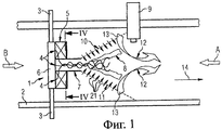
Фиг.1 - схематическое изображение первого устройства, соответствующего настоящему изобретению.1 is a schematic illustration of a first device according to the present invention.
Фиг.2 - вид в направлении, показанном стрелкой В на фиг.1.Figure 2 is a view in the direction shown by arrow B in figure 1.
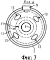
Фиг.3 - вид в направлении, показанном стрелкой А на фиг.1.Figure 3 is a view in the direction shown by arrow A in figure 1.
Фиг.4 - разрез по линии IV-IV на фиг.1.Figure 4 is a section along the line IV-IV in figure 1.
Фиг.5 - схематическое изображение второго устройства, соответствующего настоящему изобретению.5 is a schematic illustration of a second device according to the present invention.
Фиг.6 - разрез по линии VI-VI на фиг.5.6 is a section along the line VI-VI in figure 5.
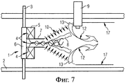
Фиг.7 - схематическое изображение третьего устройства, соответствующего настоящему изобретению.7 is a schematic illustration of a third device according to the present invention.
Фиг.8 - схематическое изображение четвертого устройства, соответствующего настоящему изобретению.Fig. 8 is a schematic illustration of a fourth device according to the present invention.
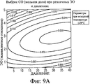
Фиг.9а, 9b и 9с - диаграммы, иллюстрирующие получение оксида углерода при использовании устройства, соответствующего настоящему изобретению.9a, 9b and 9c are diagrams illustrating the production of carbon monoxide using a device of the present invention.
Фиг. 10 - таблица, в которой приведен типичный покомпонентный состав газообразных топлив для газотурбинных двигателей.FIG. 10 is a table showing a typical exploded composition of gaseous fuels for gas turbine engines.
Описанное ниже устройство обогащает подводимое газообразное топливо для газотурбинного двигателя, включающее метан, продуктами частичного сгорания части этого подводимого топлива, включающими промежуточные продукты сгорания, в частности оксид углерода. Высокая скорость распространения пламени оксида углерода способствует поддержанию пламени горения при последующем сжигании обогащенного топлива в газотурбинном двигателе. Кроме того, оксид углерода является особенно подходящим для поддерживания пламени на границе между высоким и низким расходами, т.е. окись углерода характеризуется высоким сопротивлением возмущениям. Это свойство является желательным для предотвращения срыва пламени при горении в газотурбинном двигателе.The device described below enriches the supplied gaseous fuel for a gas turbine engine, including methane, with products of partial combustion of a part of this supplied fuel, including intermediate combustion products, in particular carbon monoxide. The high propagation speed of the carbon monoxide flame contributes to the maintenance of the combustion flame during subsequent combustion of enriched fuel in a gas turbine engine. In addition, carbon monoxide is particularly suitable for maintaining a flame at the interface between high and low flow rates, i.e. carbon monoxide is characterized by high resistance to disturbances. This property is desirable to prevent flame failure during combustion in a gas turbine engine.
Первое устройство, представленное на фиг.1-4, содержит средства 2 для подачи топлива, например трубопровод для подачи топлива под высоким давлением, включающего метан, средства (3) подвода окислителя, например подводящие трубы для впуска воздуха, средства для сжигания, например горелку 1, жаровую трубу 10 и воспламенитель 9. Подводящие трубы являются механической опорой для горелки 1. В качестве альтернативы могут быть использованы отдельные поддерживающие распорки. Топливо, включающее метан, протекает по трубопроводу для подачи топлива в направлении, показанном стрелкой 14, для питания топливом газотурбинного двигателя. Горелка 1 включает передний дисковый элемент 6, радиальный завихритель 5, содержащий завихряющие каналы 5а (см. фиг.4), и предкамеру 7.The first device, shown in figures 1-4, contains
Топливо, включающее метан, поступает с левой стороны на фиг.1 и проходит между подводящими трубами, предназначенными для впуска воздуха. Некоторая часть топлива поступает в каналы 5а завихрителя, при прохождении которых оно перемещается радиально внутрь в направлении предкамеры 7. Остальная часть топлива продолжает протекать по трубопроводу для подачи топлива и достигает жаровой трубы 10.Fuel, including methane, flows from the left side in FIG. 1 and passes between the supply pipes for air inlet. Some of the fuel enters the
Воздух подводится по подводящим трубам и инжектируется через отверстия 4, имеющиеся в задней поверхности дискового элемента 6. Топливо и воздух перемешиваются в завихренном потоке внутри предкамеры 7 таким образом, что в центральной области потока на удалении от стенок предкамеры 7 образуется горючая смесь.Air is supplied through the supply pipes and injected through the
Полученная горючая смесь поступает в жаровую трубу 10. Воспламенитель 9 инициирует первоначальное горение (пламя показано на фиг.1 позицией 8). После этого горение проходит в режиме самоподдерживания. Образование горючей смеси в центральной зоне предкамеры 7 на удалении от стенок предкамеры 7 способствует тому, чтобы горячие благодаря пламени 8 газы не контактируют со стенками жаровой трубы 10 и поэтому не повреждают их тепловым воздействием. Кроме того, в стенках жаровой трубы 10 выполнены отверстия 11 для эффузионного охлаждения, позволяющие некоторому количеству из вышеупомянутой оставшейся части топлива (несжигаемой части топлива) проходить через трубу 10 (см. стрелки 21) с тем, чтобы отводить теплоту, излучаемую пламенем 8 на трубу 10.The resulting combustible mixture enters the
Подача воздуха через подводящие трубы организована таким образом, чтобы она была достаточной для полного сгорания топлива, с которым этот воздух смешивается в предкамере 7. Другими словами, подача воздуха обеспечивается такой, чтобы смесь воздуха с топливом в предкамере 7 представляла собой топливо, богатое в такой степени, чтобы внутри жаровой трубы 10 происходило лишь частичное сгорание топлива. Это частичное сгорание приводит к получению промежуточных продуктов сгорания, в частности оксида углерода. Недостаточный подвод воздуха, кроме того, приводит к тому, что горение внутри трубопровода для подачи топлива не становится неконтролируемым процессом.The air supply through the supply pipes is organized in such a way that it is sufficient for complete combustion of the fuel with which this air is mixed in the pre-chamber 7. In other words, the air supply is provided such that the mixture of air with fuel in the pre-chamber 7 is a fuel rich in such degrees, so that only partial combustion of the fuel takes place inside the
Горение внутри жаровой трубы 10 ослабляется за счет струй 12 для разбавления, сформированных частью топлива, не подверженной сжиганию, проходящих через гасящие отверстия 13, имеющиеся в жаровой трубе 10. Подача разбавляющих струй также содействует тщательному перемешиванию несгоревшего топлива с продуктами частичного сгорания, включающими оксид углерода. Ослабление горения с помощью струй 12 для разбавления минимизирует производство нежелательных промежуточных продуктов сгорания, а именно углерода и сажи (образование углерода происходит в больший период времени по сравнению с оксидом углерода). Перемешивание горячих продуктов частичного сгорания с несжигаемым топливом охлаждает продукты сгорания, предотвращая их слишком сильный нагрев.The combustion inside the
Полученное топливо, содержащее метан и обогащенное оксидом углерода, затем подается в газотурбинный двигатель. Как объяснялось выше, оксид углерода создает эффект стабилизации процесса горения в газотурбинном двигателе. Цель заключается в том, чтобы смесь воздух/топливо, частично сжигаемая в жаровой трубе 10, была такой, чтобы произвести максимальное количество оксида углерода.The resulting fuel, containing methane and enriched in carbon monoxide, is then fed to a gas turbine engine. As explained above, carbon monoxide creates the effect of stabilizing the combustion process in a gas turbine engine. The goal is that the air / fuel mixture partially burnt in the
На фиг.9а, 9b и 9с представлены диаграммы, иллюстрирующие образование оксида углерода (в мольных долях) для различных эквивалентных отношений (ЭО) компонентов смеси и давлений. Диаграмма на фиг.9а построена для температуры топлива, включающего метан 300К (149°С); диаграмма на фиг.9b - для температуры топлива равной 400К (204°С), а диаграмма на фиг.9с - для температуры топлива 500К (260°С). Эквивалентное отношение содержаний компонентов смеси воздух/топливо (ЭО) определяется как отношение топлива к воздуху в смеси, разделенное на так называемую стехиометрическую величину. Указанная стехиометрическая величина представляет собой соотношение топливо/воздух, которое обеспечивает полное сгорание (в отличие от частичного сгорания). Таким образом, смесь, богатая топливом, характеризуется величиной ЭО больше единицы. Давления на диаграммах относятся к давлению топлива, включающего метан, в трубопроводе для подачи топлива.9a, 9b, and 9c are diagrams illustrating the formation of carbon monoxide (in mole fractions) for various equivalent ratios (EO) of mixture components and pressures. The diagram in Fig. 9a is constructed for the temperature of the fuel, including methane 300K (149 ° C); the diagram in Fig. 9b is for a fuel temperature of 400K (204 ° C), and the diagram in Fig. 9c is for a fuel temperature of 500K (260 ° C). The equivalent ratio of the contents of the components of the air / fuel mixture (EO) is defined as the ratio of fuel to air in the mixture, divided by the so-called stoichiometric value. The indicated stoichiometric value is the fuel / air ratio that provides complete combustion (as opposed to partial combustion). Thus, a mixture rich in fuel is characterized by a value of EO greater than unity. The pressure in the diagrams refers to the pressure of the fuel, including methane, in the fuel supply pipe.
Как видно, смесь воздуха и топлива при величине ЭО, составляющей примерно от 2 до 3,5, имеет тенденцию к максимальному производству оксида углерода в интервале температур от 149 до 260°С.As can be seen, the mixture of air and fuel with an EO value of approximately 2 to 3.5 tends to maximize the production of carbon monoxide in the temperature range from 149 to 260 ° C.
Второе воплощение устройства, представленное на фиг.5 и фиг.6, выполнено таким же, как и первое, за исключением того, что круговая центральная часть 16 переднего дискового элемента 6 горелки 1 выполнена с уменьшенной в некоторой степени толщиной и образованным вокруг неё кольцевым зазором 23. Центральная часть 16 удерживается внутри дискового элемента 6 с помощью опорных звеньев 31 (см. фиг.6). Топливо 15 ударяется о переднюю поверхность центральной части 16 и охлаждает ее перед тем, как оно проходит через кольцевой зазор 23 и перемешивается с воздухом в предкамере 7. В качестве альтернативы кольцевому зазору, окружающему центральную часть 16, в теле центральной части 16 могут быть выполнены сквозные отверстия. В этом случае топливо прежде чем оно будет проходить через эти отверстия и перемешиваться с воздухом в предкамере 7, будет ударяться о переднюю поверхность центральной части 16 и охлаждать ее.The second embodiment of the device shown in FIGS. 5 and 6 is the same as the first, except that the circular
На фиг.7 представлено третье воплощение устройства, которое выполнено таким же, как и первое, за исключением того, что жаровая труба 10 в качестве ее продолжения дополнена экранирующим удлинителем 17. Экранирующий удлинитель 17 имеет достаточную длину, чтобы обеспечить полное перемешивание струями 12 для разбавления несжигаемого топлива с продуктами частичного сгорания, полученными в жаровой трубе 10. Наличие экранирующего удлинителя 17 обеспечивает то, что «горячие точки» продуктов частичного сгорания не достигнут стенок трубопровода, что могло бы ослабить стенки, способствовать их коррозии и прожогу.7 shows a third embodiment of the device, which is the same as the first, except that the
На фиг.8 представлено четвертое воплощение устройства, которое выполнено таким же, как и третье, за исключением того, что выше по потоку от горелки 1 дополнительно установлен вихревой диод 18 в целях значительного уменьшения проходного сечения канала выше по потоку от места пульсаций давления и/или шума, возникающего при горении, производимого устройством, например, для того, чтобы избежать распространение возмущения от такого же устройства, подсоединенного к одному и тому же топливному коллектору 19.On Fig presents the fourth embodiment of the device, which is made the same as the third, except that upstream of the burner 1 is additionally mounted a
В устройстве, описанном выше в качестве примера, радиальный завихритель смешивает часть подачи газообразного топлива с воздухом так, чтобы создать смесь, богатую топливом, для частичного сжигания. Следует принять во внимание, что нет необходимости осуществлять это перемешивание именно с использованием радиального завихрителя. Например, перемешивание можно осуществлять с помощью осевого завихрителя или с помощью перемешивающего устройства, отличающегося от завихрителя.In the apparatus described above by way of example, a radial swirler mixes a portion of the gaseous fuel supply with air so as to create a fuel rich mixture for partial combustion. It should be borne in mind that there is no need to carry out this mixing using a radial swirler. For example, mixing can be carried out using an axial swirler or using a mixing device other than the swirler.
Устройство, описанное выше в качестве примера, обогащает оксидом углерода чистый метан, используемый в качестве топлива для газотурбинного двигателя. Конечно, при практическом коммерческом использовании устройства обогащаемым топливом газотурбинного двигателя не может быть чистый метан, а может быть использовано промышленное топливо газотурбинного двигателя. Ниже приведены примеры трех промышленных топлив для газотурбинного двигателя: биогаз, природный газ Великобритании и нефтезаводской газ. В таблице на фиг. 10 приведены типичные покомпонентные составы трех этих топлив. Количества в таблице даны в объемных процентах.The apparatus described above by way of example enriches carbon monoxide with pure methane used as fuel for a gas turbine engine. Of course, in the practical commercial use of the device, the enriched fuel of a gas turbine engine cannot be pure methane, but industrial fuel of a gas turbine engine can be used. The following are examples of three industrial fuels for a gas turbine engine: biogas, UK natural gas and refinery gas. In the table of FIG. 10 shows typical component compositions of these three fuels. The amounts in the table are given in volume percent.
В устройстве, описанном выше в качестве примера, часть газообразного топлива отбирают, частично сжигают и затем перемешивают с остальной, не сжигаемой частично частью с получением конечного топлива. Частичное сжигание регулируют так, чтобы активизировать получение промежуточного продукта сгорания - оксида углерода с тем, чтобы конечное топливо было обогащено оксидом углерода, что позволяет повысить стабильность процесса горения. Однако необходимо принимать во внимание, что частичное сжигание топлива можно регулировать с целью активизирования процесса получения промежуточного продукта сгорания, отличающегося от оксида углерода, также обеспечивающего повышение стабильности горения. Следует понимать, что задача частичного сжигания заключается в том, чтобы обеспечить промежуточные продукты сгорания, в которых располагаемые химические валентные связи не полностью насыщены. Такие продукты характеризуются высокой химической активностью (реакционную способность) и, следовательно, имеют высокие скорость распространения пламени и сопротивление возмущениям (см. упоминание об этом ранее в отношении оксида углерода). Кроме того, такие продукты способны также ослаблять или "захватывать" связи молекул несгоревшего топлива, повышая химическую активность этих молекул. Помимо того, необходимо отметить, что конечное обогащенное топливо вследствие частичного сгорания находится при повышенной температуре. Эта повышенная температура также повышает химическую активность топлива.In the apparatus described above by way of example, a portion of the gaseous fuel is withdrawn, partially burnt, and then mixed with the rest, not partially burnt, to produce the final fuel. Partial combustion is controlled so as to enhance the production of an intermediate combustion product, carbon monoxide, so that the final fuel is enriched in carbon monoxide, which improves the stability of the combustion process. However, it is necessary to take into account that partial combustion of the fuel can be regulated in order to activate the process of obtaining an intermediate product of combustion other than carbon monoxide, which also provides increased stability of combustion. It should be understood that the task of partial combustion is to provide intermediate combustion products in which the disposable chemical valence bonds are not completely saturated. Such products are characterized by high chemical activity (reactivity) and, therefore, have a high flame propagation speed and resistance to disturbances (see the mention of this earlier with respect to carbon monoxide). In addition, such products are also able to weaken or "capture" the bonds of unburned fuel molecules, increasing the chemical activity of these molecules. In addition, it should be noted that the final enriched fuel due to partial combustion is at an elevated temperature. This elevated temperature also increases the reactivity of the fuel.
Следует также понимать, что настоящее изобретение создает желательный эффект восстановления определенного количества связанного азота, присутствующего в составе топлива, посредством восстановления связанного азота до азота N2. Хотя газообразное топливо обычно содержит весьма незначительное количество связанного азота, восстановление определенного количества связанного в топливе азота полезно при стремлении получить сверхнизкий- или крайне низкий выход из топлива веществ, загрязняющих атмосферу.It should also be understood that the present invention creates the desired effect of reducing a certain amount of bound nitrogen present in the fuel composition by reducing bound nitrogen to nitrogen N 2 . Although gaseous fuels usually contain a very small amount of bound nitrogen, the recovery of a certain amount of nitrogen bound in the fuel is useful when trying to obtain an ultra-low or extremely low yield of pollutants from the fuel.
Устройство, описанное выше в качестве примера, обогащает газообразное топливо, предназначенное для подачи в газотурбинный двигатель. Следует принимать во внимание, что настоящее изобретение может быть использовано для обогащения газообразного топлива и для подачи в поршневой двигатель внутреннего сгорания, в котором требуется или желательно увеличить скорость сгорания топлива в двигателе.The device described above by way of example enriches gaseous fuel intended for supply to a gas turbine engine. It should be appreciated that the present invention can be used to enrich gaseous fuels and to feed a reciprocating internal combustion engine in which it is desired or desirable to increase the rate of combustion of fuel in the engine.
Claims (23)
Applications Claiming Priority (2)
| Application Number | Priority Date | Filing Date | Title |
|---|---|---|---|
| GB0517552.6 | 2005-08-27 | ||
| GB0517552A GB2429516B (en) | 2005-08-27 | 2005-08-27 | An apparatus for modifying the content of a gaseous fuel |
Publications (2)
| Publication Number | Publication Date |
|---|---|
| RU2008111638A RU2008111638A (en) | 2009-10-10 |
| RU2419032C2 true RU2419032C2 (en) | 2011-05-20 |
Family
ID=35198516
Family Applications (1)
| Application Number | Title | Priority Date | Filing Date |
|---|---|---|---|
| RU2008111638/06A RU2419032C2 (en) | 2005-08-27 | 2006-07-31 | Device for modification of gaseous fuel composition |
Country Status (8)
| Country | Link |
|---|---|
| US (1) | US20090249793A1 (en) |
| EP (1) | EP1917470A1 (en) |
| JP (1) | JP4660594B2 (en) |
| CN (1) | CN101253366B (en) |
| BR (1) | BRPI0615240A2 (en) |
| GB (1) | GB2429516B (en) |
| RU (1) | RU2419032C2 (en) |
| WO (1) | WO2007025822A1 (en) |
Families Citing this family (14)
| Publication number | Priority date | Publication date | Assignee | Title |
|---|---|---|---|---|
| EP1956296A1 (en) * | 2007-02-12 | 2008-08-13 | Siemens Aktiengesellschaft | Fuel supply module |
| US8413446B2 (en) * | 2008-12-10 | 2013-04-09 | Caterpillar Inc. | Fuel injector arrangement having porous premixing chamber |
| FR2953280B1 (en) * | 2009-11-30 | 2014-10-10 | Fives Stein | METHOD FOR CORRECTING COMBUSTION SETTINGS OF A COMBUSTION CHAMBER ASSEMBLY AND INSTALLATION USING THE METHOD |
| US20120052451A1 (en) * | 2010-08-31 | 2012-03-01 | General Electric Company | Fuel nozzle and method for swirl control |
| CN103703317B (en) * | 2011-07-14 | 2016-09-14 | 通用电气公司 | Fuel-cooled burner |
| JP5911387B2 (en) * | 2012-07-06 | 2016-04-27 | 三菱日立パワーシステムズ株式会社 | Gas turbine combustor and gas turbine combustor operating method |
| CA2902809C (en) | 2013-03-13 | 2018-01-23 | Industrial Turbine Company (Uk) Limited | Lean azimuthal flame combustor |
| CN104566463B (en) * | 2014-11-29 | 2016-12-07 | 哈尔滨广瀚燃气轮机有限公司 | Gas turbine low discharging burning chamber conditioner |
| AU2017223488B2 (en) * | 2016-02-23 | 2019-12-05 | Thermacell Repellents, Inc. | Fuel canister and adapter for insect repellent device |
| CN107280577B (en) * | 2016-03-31 | 2020-11-03 | 康塔有限公司 | Vacuum cleaner with a vacuum cleaner head |
| PL3301363T3 (en) * | 2016-09-30 | 2020-03-31 | Siemens Aktiengesellschaft | Combustion unit with a burner and flow measurement of turbulent flows |
| US11156164B2 (en) | 2019-05-21 | 2021-10-26 | General Electric Company | System and method for high frequency accoustic dampers with caps |
| US11174792B2 (en) | 2019-05-21 | 2021-11-16 | General Electric Company | System and method for high frequency acoustic dampers with baffles |
| US11846426B2 (en) * | 2021-06-24 | 2023-12-19 | General Electric Company | Gas turbine combustor having secondary fuel nozzles with plural passages for injecting a diluent and a fuel |
Family Cites Families (19)
| Publication number | Priority date | Publication date | Assignee | Title |
|---|---|---|---|---|
| US2225647A (en) * | 1937-07-14 | 1940-12-24 | John E Liekendael | Carburetor |
| NL253164A (en) * | 1959-07-08 | |||
| GB1465785A (en) * | 1973-03-12 | 1977-03-02 | Tokyo Gas Co Ltd | Burner and method of combustion- |
| JPS525643B2 (en) * | 1973-05-04 | 1977-02-15 | ||
| US4909727A (en) * | 1987-03-04 | 1990-03-20 | Combustion Tec, Inc. | Oxygen enriched continuous combustion in a regenerative furance |
| US4762487A (en) * | 1987-08-13 | 1988-08-09 | Gas Research Institute | Diode supplied pulsed combustor |
| US6564556B2 (en) * | 1992-10-27 | 2003-05-20 | J. Lyell Ginter | High efficiency low pollution hybrid brayton cycle combustor |
| JP3335713B2 (en) * | 1993-06-28 | 2002-10-21 | 株式会社東芝 | Gas turbine combustor |
| US5394688A (en) * | 1993-10-27 | 1995-03-07 | Westinghouse Electric Corporation | Gas turbine combustor swirl vane arrangement |
| US5725366A (en) * | 1994-03-28 | 1998-03-10 | Institute Of Gas Technology | High-heat transfer, low-nox oxygen-fuel combustion system |
| JP3196549B2 (en) * | 1995-01-09 | 2001-08-06 | 株式会社日立製作所 | Power generation system with fuel reformer |
| DE19536836C2 (en) * | 1995-10-02 | 2003-11-13 | Alstom | Process for operating a power plant |
| DE19654022A1 (en) * | 1996-12-21 | 1998-06-25 | Abb Research Ltd | Process for operating a gas turbine group |
| KR100659678B1 (en) * | 1999-08-17 | 2006-12-21 | 닛폰화네스코교 가부시기가이샤 | Combustion method and burner |
| DE10055613A1 (en) * | 2000-11-09 | 2002-05-23 | Xcellsis Gmbh | Process for introducing fuel and/or thermal energy into gas stream flowing to catalytic reactor comprises feeding part of gas stream to outer chamber |
| DE10061526A1 (en) * | 2000-12-11 | 2002-06-20 | Alstom Switzerland Ltd | Premix burner arrangement for operating a combustion chamber |
| JP4683787B2 (en) * | 2001-03-09 | 2011-05-18 | 大阪瓦斯株式会社 | Burner device and gas turbine engine |
| EP1359377B1 (en) * | 2002-05-02 | 2010-09-01 | Alstom Technology Ltd | Catalytic burner |
| US20050144961A1 (en) * | 2003-12-24 | 2005-07-07 | General Electric Company | System and method for cogeneration of hydrogen and electricity |
-
2005
- 2005-08-27 GB GB0517552A patent/GB2429516B/en not_active Expired - Fee Related
-
2006
- 2006-07-31 US US11/990,467 patent/US20090249793A1/en not_active Abandoned
- 2006-07-31 JP JP2008527424A patent/JP4660594B2/en not_active Expired - Fee Related
- 2006-07-31 CN CN2006800312543A patent/CN101253366B/en not_active Expired - Fee Related
- 2006-07-31 BR BRPI0615240-6A patent/BRPI0615240A2/en not_active IP Right Cessation
- 2006-07-31 WO PCT/EP2006/064863 patent/WO2007025822A1/en active Search and Examination
- 2006-07-31 EP EP06792622A patent/EP1917470A1/en not_active Withdrawn
- 2006-07-31 RU RU2008111638/06A patent/RU2419032C2/en not_active IP Right Cessation
Also Published As
| Publication number | Publication date |
|---|---|
| JP2009506250A (en) | 2009-02-12 |
| JP4660594B2 (en) | 2011-03-30 |
| US20090249793A1 (en) | 2009-10-08 |
| GB2429516A (en) | 2007-02-28 |
| EP1917470A1 (en) | 2008-05-07 |
| RU2008111638A (en) | 2009-10-10 |
| CN101253366B (en) | 2013-05-15 |
| WO2007025822A1 (en) | 2007-03-08 |
| GB2429516B (en) | 2010-12-29 |
| BRPI0615240A2 (en) | 2011-05-10 |
| GB0517552D0 (en) | 2005-10-05 |
| CN101253366A (en) | 2008-08-27 |
Similar Documents
| Publication | Publication Date | Title |
|---|---|---|
| RU2419032C2 (en) | Device for modification of gaseous fuel composition | |
| US7513115B2 (en) | Flashback suppression system for a gas turbine combustor | |
| US8176739B2 (en) | Coanda injection system for axially staged low emission combustors | |
| JP2713627B2 (en) | Gas turbine combustor, gas turbine equipment including the same, and combustion method | |
| JP5400936B2 (en) | Method and apparatus for burning fuel in a gas turbine engine | |
| US7874157B2 (en) | Coanda pilot nozzle for low emission combustors | |
| US20100095649A1 (en) | Staged combustion systems and methods | |
| JP5574659B2 (en) | Continuous combustion gas turbine and method for reducing combustor emissions for such a gas turbine | |
| US5158445A (en) | Ultra-low pollutant emission combustion method and apparatus | |
| CN1039362C (en) | Fuei-burner method and apparatus | |
| JP2011027395A (en) | Gas turbine premixing system | |
| WO2001055646A1 (en) | Low cost, low emissions natural gas combustor | |
| JP2010085087A5 (en) | ||
| JP2010261697A (en) | Fuel blanket by inert gas or low-reactive fuel layer for preventing flame-holding in premixer | |
| US20030101729A1 (en) | Retrofittable air assisted fuel injection method to control gaseous and acoustic emissions | |
| CA2537926C (en) | Pilot combustor for stabilizing combustion in gas turbine engines | |
| JP2009528503A (en) | Gas turbine combustor and operation method of gas turbine combustor | |
| JP4352821B2 (en) | Lean pre-evaporation premix combustor | |
| JPH0555763B2 (en) | ||
| JP4352824B2 (en) | Lean pre-evaporation premix combustor | |
| JP4482858B2 (en) | Lean pre-evaporation premix combustor | |
| WO2023187215A1 (en) | Gas burner with low nox emission | |
| RU2428627C1 (en) | Burner device | |
| JPS6055724B2 (en) | gas turbine combustor | |
| JPH08178291A (en) | Gas turbine burner |
Legal Events
| Date | Code | Title | Description |
|---|---|---|---|
| MM4A | The patent is invalid due to non-payment of fees |
Effective date: 20140801 |