JP2010261697A - Fuel blanket by inert gas or low-reactive fuel layer for preventing flame-holding in premixer - Google Patents
Fuel blanket by inert gas or low-reactive fuel layer for preventing flame-holding in premixer Download PDFInfo
- Publication number
- JP2010261697A JP2010261697A JP2010043739A JP2010043739A JP2010261697A JP 2010261697 A JP2010261697 A JP 2010261697A JP 2010043739 A JP2010043739 A JP 2010043739A JP 2010043739 A JP2010043739 A JP 2010043739A JP 2010261697 A JP2010261697 A JP 2010261697A
- Authority
- JP
- Japan
- Prior art keywords
- fuel
- passage
- reactive fuel
- low
- inert gas
- Prior art date
- Legal status (The legal status is an assumption and is not a legal conclusion. Google has not performed a legal analysis and makes no representation as to the accuracy of the status listed.)
- Withdrawn
Links
Images


Classifications
-
- F—MECHANICAL ENGINEERING; LIGHTING; HEATING; WEAPONS; BLASTING
- F23—COMBUSTION APPARATUS; COMBUSTION PROCESSES
- F23R—GENERATING COMBUSTION PRODUCTS OF HIGH PRESSURE OR HIGH VELOCITY, e.g. GAS-TURBINE COMBUSTION CHAMBERS
- F23R3/00—Continuous combustion chambers using liquid or gaseous fuel
- F23R3/28—Continuous combustion chambers using liquid or gaseous fuel characterised by the fuel supply
- F23R3/286—Continuous combustion chambers using liquid or gaseous fuel characterised by the fuel supply having fuel-air premixing devices
-
- F—MECHANICAL ENGINEERING; LIGHTING; HEATING; WEAPONS; BLASTING
- F23—COMBUSTION APPARATUS; COMBUSTION PROCESSES
- F23C—METHODS OR APPARATUS FOR COMBUSTION USING FLUID FUEL OR SOLID FUEL SUSPENDED IN A CARRIER GAS OR AIR
- F23C2900/00—Special features of, or arrangements for combustion apparatus using fluid fuels or solid fuels suspended in air; Combustion processes therefor
- F23C2900/07022—Delaying secondary air introduction into the flame by using a shield or gas curtain
-
- F—MECHANICAL ENGINEERING; LIGHTING; HEATING; WEAPONS; BLASTING
- F23—COMBUSTION APPARATUS; COMBUSTION PROCESSES
- F23L—SUPPLYING AIR OR NON-COMBUSTIBLE LIQUIDS OR GASES TO COMBUSTION APPARATUS IN GENERAL ; VALVES OR DAMPERS SPECIALLY ADAPTED FOR CONTROLLING AIR SUPPLY OR DRAUGHT IN COMBUSTION APPARATUS; INDUCING DRAUGHT IN COMBUSTION APPARATUS; TOPS FOR CHIMNEYS OR VENTILATING SHAFTS; TERMINALS FOR FLUES
- F23L2900/00—Special arrangements for supplying or treating air or oxidant for combustion; Injecting inert gas, water or steam into the combustion chamber
- F23L2900/07002—Injecting inert gas, other than steam or evaporated water, into the combustion chambers
-
- F—MECHANICAL ENGINEERING; LIGHTING; HEATING; WEAPONS; BLASTING
- F23—COMBUSTION APPARATUS; COMBUSTION PROCESSES
- F23L—SUPPLYING AIR OR NON-COMBUSTIBLE LIQUIDS OR GASES TO COMBUSTION APPARATUS IN GENERAL ; VALVES OR DAMPERS SPECIALLY ADAPTED FOR CONTROLLING AIR SUPPLY OR DRAUGHT IN COMBUSTION APPARATUS; INDUCING DRAUGHT IN COMBUSTION APPARATUS; TOPS FOR CHIMNEYS OR VENTILATING SHAFTS; TERMINALS FOR FLUES
- F23L2900/00—Special arrangements for supplying or treating air or oxidant for combustion; Injecting inert gas, water or steam into the combustion chamber
- F23L2900/07009—Injection of steam into the combustion chamber
Abstract
Description
本発明は、ガスタービンエンジンの燃焼器用空気燃料ミキサに関し、更に、空気及び燃料を混合するための方法に関する。 The present invention relates to an air fuel mixer for a combustor of a gas turbine engine, and further relates to a method for mixing air and fuel.
ガスタービン製造業者は、通常、望ましくない空気汚染エミッションを産出することなく、高効率で運転する新しいガスタービンを実現するための研究設計プログラムに取り組んでいる。従来の炭化水素燃料を燃焼するガスタービンにより通常産出される主な大気汚染エミッションは、窒素酸化物、一酸化炭素、及び未燃炭化水素である。空気吸入エンジンにおける窒素分子の酸化は、燃焼システムの反応ゾーンにおける高温ガス最高温度に高度に依存する。窒素酸化物(NOx)を形成する化学反応率は、温度の指数関数であり、従って、これらの反応によって生成されるNOxは、サーマルNOxとも呼ばれる。燃焼室の高温ガスの温度が十分に低いレベルに制御される場合、サーマルNOxは産出されないことになる。 Gas turbine manufacturers are typically engaged in research and design programs to realize new gas turbines that operate at high efficiency without producing undesirable air pollution emissions. The main air pollution emissions normally produced by gas turbines burning conventional hydrocarbon fuels are nitrogen oxides, carbon monoxide, and unburned hydrocarbons. The oxidation of molecular nitrogen in air-breathing engines is highly dependent on the hot gas maximum temperature in the reaction zone of the combustion system. The chemical reaction rate that forms nitrogen oxides (NOx) is an exponential function of temperature, and therefore the NOx produced by these reactions is also referred to as thermal NOx. If the temperature of the hot gas in the combustion chamber is controlled to a sufficiently low level, thermal NOx will not be produced.
燃焼器の反応ゾーンの温度をサーマルNOxが形成されるレベル未満に制御する1つの方法は、燃焼の前に燃料及び空気を予混合して希薄混合気にすることである。希薄予混合燃焼器の反応ゾーン内に存在する過剰な空気の熱質量は、熱を吸収し、燃焼生成物の温度上昇をサーマルNOxが形成されないレベルにまで低減する。 One way to control the temperature of the combustor reaction zone below the level at which thermal NOx is formed is to premix fuel and air into a lean mixture prior to combustion. Excess air thermal mass present in the reaction zone of the lean premix combustor absorbs heat and reduces the temperature rise of the combustion products to a level where thermal NOx is not formed.
燃料及び空気の希薄予混合状態で作動する乾式低エミッション燃焼器と関連した問題が潜在的に幾つか存在しており、この乾式低エミッション燃焼器では、燃料及び空気の可燃性混合気が、燃焼器の反応ゾーンの外部にある該燃焼器の予混合セクション内に存在している。火炎が燃焼器反応ゾーンから予混合セクション内に伝播し、該火炎が燃料噴射コラム(噴射直交流)又はベーン後縁の後方の伴流内部に保持される場合に発生する逆火、或いは、予混合セクション内における燃料/空気混合気のドエル時間及び温度が点火装置なしで燃焼を開始するのに十分である場合に発生する自己点火に起因して、燃焼が予混合セクション内で発生する傾向が存在する可能性がある。予混合セクション内における燃焼の結果として、エミッション性能の低下、及び/又は通常は燃焼の熱に耐えるようには設計されていない予混合セクションへの過熱及び損傷を生じる。従って、解決すべき問題は、予混合器の内部で燃焼を発生させる逆火又は自己点火を防止することである。 There are some potential problems associated with dry low-emission combustors operating in lean premixed fuel and air conditions, where the combustible mixture of fuel and air is burned Present in the premixing section of the combustor outside the reactor reaction zone. Backfire that occurs when a flame propagates from the combustor reaction zone into the premixing section and is held in the wake behind the fuel injection column (injection cross flow) or vane trailing edge, or Combustion tends to occur in the premixing section due to self-ignition that occurs when the fuel / air mixture dwell time and temperature in the mixing section are sufficient to initiate combustion without an igniter. May exist. As a result of combustion in the premixing section, it results in reduced emissions performance and / or overheating and damage to the premixing section that is not normally designed to withstand the heat of combustion. Thus, the problem to be solved is to prevent flashback or autoignition that causes combustion inside the premixer.
更に、予混合器から流出し且つ燃焼器の反応ゾーンに流入する燃料及び空気の混合気は、所望のエミッション性能を達成するために極めて均一でなければならない。燃料/空気混合気濃度が平均値よりも大幅に濃厚である流れ場の領域が存在する場合には、これら領域における燃焼生成物は、平均値よりも高い温度に達することになり、サーマルNOxが形成される可能性がある。このことは、温度及び滞留時間の組み合わせに応じて決まるNOxエミッション目標に適合できない結果となる可能性がある。燃料/空気混合気濃度が、平均値よりも大幅に希薄である流れ場の領域が存在する場合には、炭化水素及び/又は一酸化炭素を平衡レベルにまで酸化させ得ない状態で消炎が発生する可能性がある。これにより、一酸化炭素(CO)及び/又は未燃炭化水素(UHC)エミッション目標に適合できなくなる可能性がある。従って、解決すべきもう1つの問題点は、予混合器から流出する燃料/空気混合気濃度分布を、エミッション性能目標に適合するために十分に均一なものにすることである。 Furthermore, the fuel and air mixture exiting the premixer and entering the reaction zone of the combustor must be very uniform to achieve the desired emission performance. If there are flow field regions where the fuel / air mixture concentration is significantly richer than the average value, the combustion products in these regions will reach a temperature above the average value and the thermal NOx It may be formed. This can result in failure to meet NOx emission goals that depend on the combination of temperature and residence time. When there is a flow field region where the fuel / air mixture concentration is significantly leaner than the average value, extinction occurs in a state where hydrocarbons and / or carbon monoxide cannot be oxidized to the equilibrium level. there's a possibility that. This may result in failure to meet carbon monoxide (CO) and / or unburned hydrocarbon (UHC) emission goals. Therefore, another problem to be solved is to make the fuel / air mixture concentration distribution exiting the premixer sufficiently uniform to meet emission performance goals.
更にまた、多くの用途においてガスタービンに課されたエミッション性能目標を満たすためには、大半の炭化水素燃料において、燃料/空気混合気濃度を希薄可燃性限界値に近いレベルにまで低下させることが必要である。このことは、火炎伝播速度の低下並びにエミッション低減をもたらすことができる。その結果として、希薄予混合燃焼器は、より多くの従来型の拡散火炎燃焼器よりも安定性が劣る傾向があり、高レベル燃焼により誘起される動的圧力変動(燃焼ダイナミックスとも呼ばれる)が生じることが多い。燃焼ダイナミックスは、摩耗又は疲労による燃焼器及びタービンハードウェア損傷、逆火、或いはブローアウトのような、悪影響をもたらす可能性がある。従って、解決すべきもう1つの問題は、燃焼ダイナミックスを許容可能な低レベルに制御することである。 Furthermore, in order to meet the emission performance targets imposed on gas turbines in many applications, the fuel / air mixture concentration can be reduced to a level close to the lean flammability limit in most hydrocarbon fuels. is necessary. This can result in reduced flame propagation speed as well as reduced emissions. As a result, lean premixed combustors tend to be less stable than more conventional diffusion flame combustors, and dynamic pressure fluctuations (also called combustion dynamics) induced by high-level combustion Often occurs. Combustion dynamics can have adverse effects such as combustor and turbine hardware damage, flashback, or blowout due to wear or fatigue. Thus, another problem to be solved is to control the combustion dynamics to an acceptable low level.
エミッション低減のための希薄予混合燃料噴射装置は、二十年間以上にわたって高出力産業用ガスタービンでの実施が減少してきているが、産業界全体で使用されている。このような装置の代表的な実施例が、米国特許第5,259,184号に記載されている。このような装置により、ガスタービン排出エミッション低減の分野で進歩を遂げてきた。先行技術の拡散火炎バーナに比較して、数倍又はそれ以上の窒素酸化物NOxエミッションの低減が、蒸気又は水などの希釈剤噴射を利用することなく達成された。 Lean premixed fuel injectors to reduce emissions are used throughout the industry, although their implementation in high power industrial gas turbines has been declining for over two decades. An exemplary embodiment of such a device is described in US Pat. No. 5,259,184. With such devices, progress has been made in the field of reducing gas turbine exhaust emissions. Compared to prior art diffusion flame burners, several or more reductions in nitrogen oxide NOx emissions were achieved without the use of diluent injection such as steam or water.
しかしながら上述のように、エミッション性能におけるこれらの向上は、幾つかの問題が発生するリスクの下で得られた。具体的には、この装置の予混合セクション内での逆火及び保炎により、過熱に起因したエミッション性能の低下及び/又はハードウェア損傷が生じる。更に、高レベルの燃焼誘起動的圧力作用により、摩耗又は高サイクル疲労損傷に起因した、ガスタービンの燃焼システム部品及び/又は他の部品の有効寿命の低下が生じる。更にまた、高レベルの動的圧力作用、逆火又はブローアウトに至る状態を回避するためには、ガスタービンの運転上の複雑さが増大し、及び/又はガスタービンに対する運転制約条件が必要となる。 However, as mentioned above, these improvements in emissions performance were obtained at the risk of some problems occurring. Specifically, flashback and flame holding within the premixing section of the device results in reduced emissions performance and / or hardware damage due to overheating. In addition, high levels of combustion-induced dynamic pressure effects result in a reduction in the useful life of gas turbine combustion system components and / or other components due to wear or high cycle fatigue damage. Furthermore, to avoid conditions leading to high levels of dynamic pressure action, flashback or blowout, the operational complexity of the gas turbine is increased and / or operational constraints on the gas turbine are required. Become.
これらの問題に加えて、従来型の希薄予混合式燃焼器は、予混合器から流出して反応ゾーンに入る燃料及び空気の完全な均一予混合では実現可能な最大エミッション低減が達成することができなかった。 In addition to these problems, conventional lean premix combustors can achieve the maximum emission reduction achievable with complete uniform premixing of fuel and air exiting the premixer and entering the reaction zone. could not.
1つの実施形態によれば、ガスタービン燃焼器用の予混合器は、高反応性燃料を噴射するように構成された第1の通路と、不活性ガス又は化学的に低反応性の燃料或いは両方の混合気を噴射するように構成された第2の通路と、を備え、第2の通路が、不活性ガス又は低反応性燃料或いは両方の混合気の層を形成し、高反応性燃料の層をブランケットするように構成されている。 According to one embodiment, a premixer for a gas turbine combustor includes a first passage configured to inject highly reactive fuel and an inert gas or a chemically less reactive fuel or both. A second passage configured to inject an air-fuel mixture, wherein the second passage forms a layer of an inert gas or a low-reactive fuel or a mixture of both, and the high-reactive fuel Configured to blanket the layers.
別の実施形態によれば、ガスタービン燃焼器用の予混合器は、同心管体のペアを各々が含む複数のノズルを備え、同心管体のペアが、高反応性燃料を噴射するよう構成された第1の管体と、該第1の管体を囲み、且つ不活性ガス又は低反応性燃料或いは両方の混合気を形成し、高反応性燃料の層をブランケットするように構成された第2の管体とを含む。 According to another embodiment, a premixer for a gas turbine combustor comprises a plurality of nozzles each including a pair of concentric tubes, the pair of concentric tubes configured to inject highly reactive fuel. A first tubular body and a first tubular body configured to blanket the first tubular body and form a mixture of an inert gas, a low-reactive fuel, or both, and a high-reactive fuel layer. 2 tubes.
更に別の実施形態によれば、ガスタービン燃焼器用の可燃混合気を形成する方法は、高反応性燃料を噴射する段階と、不活性ガス又は低反応性燃料或いは両方の混合気を噴射して、高反応性燃料をブランケットする段階と、を含む。 According to yet another embodiment, a method of forming a combustible mixture for a gas turbine combustor includes injecting a highly reactive fuel and injecting an inert gas, a low reactive fuel, or a mixture of both. Blanketing the highly reactive fuel.
図1及び2を参照すると、燃焼器の予混合器のハブ及びシュラウドセクション2は、第1の通路4及び第2の通路6を含む。燃料10は、第1の通路4から提供される。燃料10は、例えば、水素(H2O)又は高水素レベルを有する燃料など、高反応性燃料とすることができる。燃料10はまた、例えば、天然ガス、液体燃料、石炭ガス化からのガス、合成燃料、及び炭化水素燃料もしくは高水素レベルの燃料とすることができる。燃料10は、空気12の流れと混合されて、燃焼用の燃料空気混合気を形成する。不活性ガス及び/又は低反応性燃料はまた、高反応性燃料の直後に噴射することができる点は理解されたい。これは、場合によっては、燃料噴射により誘起される再循環ゾーンの反応性を低下させ、従って、保炎傾向を低減することができる。
With reference to FIGS. 1 and 2, the hub and
不活性ガス又は低反応性燃料、或いは両方の混合気8は、第2の通路6から提供される。不活性ガスは、例えば、窒素(N2)蒸気(H2O)、又は二酸化炭素(CO2)或いはこれらの組み合わせとすることができる。第1の通路すなわち燃料通路4は、燃料10が保持されて保炎を引き起こす可能性があるハブ及びシュラウドセクション2から燃料10を離して維持するよう構成される。図2に詳細に示されるように、第2の通路6は、漸次的に拡大する区域を有する。第2の通路6は、図1に示す燃料通路4よりも幅広で、燃料層10を完全に覆うようにハブ及びシュラウドセクション2に延びる。
Inert gas or low-reactive fuel, or a mixture 8 of both, is provided from the
流れ関連の問題に起因する燃焼の早期発生を制御するために、図2に示すような不活性ガス又は低反応性燃料、或いはその両方の混合気の層によって高反応性の燃料10をブランケットすることにより、保炎マージンを増大させることができる。水素のような高反応性燃料では、流れの外乱は、燃料を捕捉し、保炎問題が起き始める可能性がある。
In order to control the early occurrence of combustion due to flow-related problems, the highly
通路4、6は、不活性ガス又は低反応性燃料8によって覆われる高反応性燃料10の層を緩慢に拡散及び形成し、燃料空気境界面間の反応を遅らせるのに使用される。図2に詳細に説明するように、第2の通路6は、漸次的に拡大する区域を有するが、第1及び第2の通路4、6の両方は、漸次的に拡大する区域を有し、不活性ガス又は低反応性燃料及び高反応性燃料のストリームを該漸次的に拡大する区域を介して緩慢に拡散させることができる点を理解されたい。通路4、6は、高反応性燃料10を覆ってほぼ均一な分布をもたらし、不活性ガス又は低反応性燃料8の層を形成するよう構成される。漸次的拡大による流れの導入はまた、ベーン表面で見られるジェット誘起分離を低減する。
The
また、高反応性燃料10に対して、燃料導入スペース近傍での空気燃料相互作用を制御することによって保炎を防止することができる。通路4、6はまた、空気/燃料混合気境界面を制御して、点火を制御するよう構成される。不活性ガス又は低反応性燃料による高反応性燃料のブランケットはまた、図3に示す同心管体構成でも使用することができる。
Further, flame holding can be prevented by controlling the air fuel interaction in the vicinity of the fuel introduction space with respect to the highly
燃焼器14は、ノズル16を備えた予混合器を含む。各ノズル16は、内側管体18及び外側管体20を有する、同心管体を含む。内側管体18は、例えば、高反応性燃料である燃料22を提供し、外側管体20は、燃料22をブランケットする、不活性ガス又は低反応性燃料24を提供する。燃焼器14に空気流26が提供され、燃料22と可燃混合気を形成する。空気流26は、スワール(旋回)28及び逆スワール28を含むことができる。逆火防止器32を設けることもできる。
The
予混合器は、高水素燃料又は高水素シンガス燃料を必要とする機械に使用することができる。 The premixer can be used in machines that require high hydrogen fuel or high hydrogen syngas fuel.
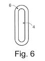
図4から11を参照すると、通路4、6は、種々の構成を有することができる。例えば、通路4、6は、図4に示すように円形、又は図5に示すように矩形とすることができる。通路4、6はまた、図6から8に示す形状の組み合わせとすることができる。図10に示すように、通路4の1つは、複数の通路として形成してもよい。また、両方の通路を複数の通路として形成することができる点は理解されたい。図11を参照すると、通路は、互いに垂直に設けることができる。
With reference to FIGS. 4 to 11, the
現時点で最も実用的且つ好ましい実施形態であると考えられるものに関して本発明を説明してきたが、本発明は、開示した実施形態に限定されるものではなく、逆に添付の請求項の技術的思想及び範囲内に含まれる様々な修正形態及び均等な構成を保護するものであることを理解されたい。 Although the present invention has been described with respect to what is considered to be the most practical and preferred embodiments at the present time, the invention is not limited to the disclosed embodiments, and conversely, the technical spirit of the appended claims It should also be understood that various modifications and equivalent arrangements included within the scope are protected.
2 ハブ及びシュラウドセクション
4 第1のスロット
6 第2のスロット
8 不活性ガス/低反応性燃料
10 燃料
12 空気流
14 燃焼器
16 ノズル
18 内側管体
20 外側管体
22 燃料
24 不活性ガス/低反応性燃料
26 空気流
28 スワール(旋回)
30 逆スワール
32 逆火防止器
2 Hub and
30
Claims (15)
高反応性燃料(10、22)を噴射するように構成された第1の通路(4、18)と、
不活性ガス又は低反応性燃料(8、24)或いは両方の混合気を噴射するように構成された第2の通路(6、20)と、
を備え、
前記第2の通路(6、20)が、前記不活性ガス又は低反応性燃料(8、24)或いは両方の混合気の層を形成し、前記高反応性燃料(10、22)の層をブランケットするように構成されている予混合器。 A premixer for a gas turbine combustor (14) comprising:
A first passageway (4, 18) configured to inject highly reactive fuel (10, 22);
A second passageway (6, 20) configured to inject an inert gas or a low-reactive fuel (8, 24) or a mixture of both;
With
The second passage (6, 20) forms a layer of the inert gas or the low-reactive fuel (8, 24) or a mixture of both, and the layer of the high-reactive fuel (10, 22). A premixer that is configured to blanket.
請求項1に記載の予混合器。 The second passage (6) is wider than the first passage (4);
The premixer according to claim 1.
請求項1又は2に記載の予混合器。 Said second passage (6) comprises an enlarged area;
The premixer according to claim 1 or 2.
請求項1から3の何れか1項に記載の予混合器。 The first passage (4) is configured to diffuse the highly reactive fuel (10) away from the hub and shroud section (2);
The premixer according to any one of claims 1 to 3.
請求項4に記載の予混合器。 The inert gas or low-reactivity fuel (8, 24) so that the second passage (6) extends to the hub and shroud section (2) and completely covers the first passage (4). ) Or diffuse the mixture of both,
The premixer according to claim 4.
前記同心管体のペア(18、20)が、前記高反応性燃料(22)を噴射するよう構成された第1の管体(18)と、該第1の管体(18)を囲み、且つ前記不活性ガス又は低反応性燃料(24)或いは両方の混合気を形成し、前記高反応性燃料(22)の層をブランケットするように構成された第2の管体(20)とを含む、
請求項1に記載のガスタービン燃焼器(14)用の予混合器。 A plurality of nozzles (16) each comprising a pair of concentric tubes (18, 20) defining the first passage and the second passage;
A pair of concentric tubes (18, 20) surrounding a first tube (18) configured to inject the highly reactive fuel (22); and the first tube (18); And a second tube (20) configured to blanket the layer of the highly reactive fuel (22) to form a mixture of the inert gas and / or the low reactive fuel (24) or both. Including,
A premixer for a gas turbine combustor (14) according to claim 1.
請求項1から6の何れか1項に記載の予混合器。 A backfire preventer (32),
The premixer according to any one of claims 1 to 6.
高反応性燃料(10、22)を噴射する段階と、
不活性ガス又は低反応性燃料(8、24)或いは両方の混合気を噴射して、前記高反応性燃料(10、22)をブランケットする段階と、
を含む方法。 A method of forming a combustible mixture for a gas turbine combustor comprising:
Injecting highly reactive fuel (10, 22);
Injecting an inert gas or a low reactive fuel (8, 24) or a mixture of both to blanket the high reactive fuel (10, 22);
Including methods.
前記不活性ガス又は低反応性燃料(8、24)或いは両方の混合気を噴射する段階が、該不活性ガス又は低反応性燃料(8、24)或いは両方の混合気を第2の通路(6、20)から噴射する段階を含む、
請求項8に記載の方法。 Injecting the highly reactive fuel (10, 22) comprises injecting the highly reactive fuel (10, 22) from a first passage (4, 18);
The step of injecting the inert gas or the low-reactive fuel (8, 24) or a mixture of both comprises passing the inert gas or the low-reactive fuel (8, 24) or a mixture of both into the second passage ( 6 and 20),
The method of claim 8.
請求項9に記載の方法。 The second passage (6) is wider than the first passage (4);
The method of claim 9.
請求項9又は10に記載の方法。 The second passage (6) has a gradually expanding area;
The method according to claim 9 or 10.
前記不活性ガス又は低反応性燃料(8、24)或いは両方の混合気を噴射する段階が、前記第2の通路(6)を定め且つ前記第1の管体(18)と同心の第2の管体(20)から前記不活性ガス又は低反応性燃料(24)或いは両方の混合気を噴射する段階を含む、
請求項8に記載の方法。 Injecting the highly reactive fuel (22) comprises injecting the highly reactive fuel (22) from a first tube (18) defining the first passage;
The step of injecting the inert gas or the low-reactivity fuel (8, 24) or a mixture of both defines a second passage (6) and a second concentric with the first tube (18). Injecting the inert gas or the low-reactive fuel (24) or a mixture of both from the tube (20).
The method of claim 8.
請求項8から12の何れか1項に記載の方法。 Providing an air flow (12, 26) to further mix the inert gas or low-reactivity fuel (24) or a mixture of both and the high-reactivity fuel (10, 22);
The method according to any one of claims 8 to 12.
請求項13に記載の方法。 Providing a swirl (28) to the air stream (26);
The method of claim 13.
請求項13に記載の方法。 Further comprising providing a reverse swirl (30) to the air stream (26);
The method of claim 13.
Applications Claiming Priority (1)
| Application Number | Priority Date | Filing Date | Title |
|---|---|---|---|
| US12/435,651 US20100281876A1 (en) | 2009-05-05 | 2009-05-05 | Fuel blanketing by inert gas or less reactive fuel layer to prevent flame holding in premixers |
Publications (1)
| Publication Number | Publication Date |
|---|---|
| JP2010261697A true JP2010261697A (en) | 2010-11-18 |
Family
ID=42556427
Family Applications (1)
| Application Number | Title | Priority Date | Filing Date |
|---|---|---|---|
| JP2010043739A Withdrawn JP2010261697A (en) | 2009-05-05 | 2010-03-01 | Fuel blanket by inert gas or low-reactive fuel layer for preventing flame-holding in premixer |
Country Status (4)
| Country | Link |
|---|---|
| US (1) | US20100281876A1 (en) |
| EP (1) | EP2251604A1 (en) |
| JP (1) | JP2010261697A (en) |
| CN (1) | CN101881454A (en) |
Cited By (1)
| Publication number | Priority date | Publication date | Assignee | Title |
|---|---|---|---|---|
| JP2013181746A (en) * | 2012-03-01 | 2013-09-12 | General Electric Co <Ge> | System and method for reducing combustion dynamics in combustor |
Families Citing this family (17)
| Publication number | Priority date | Publication date | Assignee | Title |
|---|---|---|---|---|
| US8448442B2 (en) * | 2011-05-19 | 2013-05-28 | General Electric Company | Flexible combustor fuel nozzle |
| DE102012216505A1 (en) * | 2012-09-17 | 2014-03-20 | Siemens Aktiengesellschaft | Gasification burner with inert gas curtain between pilot burner and dust burner |
| US9745840B2 (en) | 2012-11-16 | 2017-08-29 | Us Well Services Llc | Electric powered pump down |
| US10232332B2 (en) | 2012-11-16 | 2019-03-19 | U.S. Well Services, Inc. | Independent control of auger and hopper assembly in electric blender system |
| US9995218B2 (en) | 2012-11-16 | 2018-06-12 | U.S. Well Services, LLC | Turbine chilling for oil field power generation |
| US11476781B2 (en) | 2012-11-16 | 2022-10-18 | U.S. Well Services, LLC | Wireline power supply during electric powered fracturing operations |
| US9893500B2 (en) | 2012-11-16 | 2018-02-13 | U.S. Well Services, LLC | Switchgear load sharing for oil field equipment |
| US11449018B2 (en) | 2012-11-16 | 2022-09-20 | U.S. Well Services, LLC | System and method for parallel power and blackout protection for electric powered hydraulic fracturing |
| US10407990B2 (en) | 2012-11-16 | 2019-09-10 | U.S. Well Services, LLC | Slide out pump stand for hydraulic fracturing equipment |
| US10288291B2 (en) * | 2014-08-15 | 2019-05-14 | General Electric Company | Air-shielded fuel injection assembly to facilitate reduced NOx emissions in a combustor system |
| US10598258B2 (en) | 2017-12-05 | 2020-03-24 | U.S. Well Services, LLC | Multi-plunger pumps and associated drive systems |
| US10648311B2 (en) | 2017-12-05 | 2020-05-12 | U.S. Well Services, LLC | High horsepower pumping configuration for an electric hydraulic fracturing system |
| US10648270B2 (en) | 2018-09-14 | 2020-05-12 | U.S. Well Services, LLC | Riser assist for wellsites |
| US11578577B2 (en) | 2019-03-20 | 2023-02-14 | U.S. Well Services, LLC | Oversized switchgear trailer for electric hydraulic fracturing |
| WO2020231483A1 (en) | 2019-05-13 | 2020-11-19 | U.S. Well Services, LLC | Encoderless vector control for vfd in hydraulic fracturing applications |
| WO2020251978A1 (en) | 2019-06-10 | 2020-12-17 | U.S. Well Services, LLC | Integrated fuel gas heater for mobile fuel conditioning equipment |
| US11459863B2 (en) | 2019-10-03 | 2022-10-04 | U.S. Well Services, LLC | Electric powered hydraulic fracturing pump system with single electric powered multi-plunger fracturing pump |
Family Cites Families (9)
| Publication number | Priority date | Publication date | Assignee | Title |
|---|---|---|---|---|
| US5259184A (en) * | 1992-03-30 | 1993-11-09 | General Electric Company | Dry low NOx single stage dual mode combustor construction for a gas turbine |
| JP3282944B2 (en) * | 1994-07-18 | 2002-05-20 | トヨタ自動車株式会社 | Low NOx burner |
| DE59905864D1 (en) * | 1998-08-28 | 2003-07-10 | Voest Alpine Ind Anlagen | MULTIFUNCTIONAL LANCE AND THEIR USE |
| US6179608B1 (en) * | 1999-05-28 | 2001-01-30 | Precision Combustion, Inc. | Swirling flashback arrestor |
| US7513115B2 (en) * | 2005-05-23 | 2009-04-07 | Power Systems Mfg., Llc | Flashback suppression system for a gas turbine combustor |
| US20070130830A1 (en) * | 2005-12-14 | 2007-06-14 | Balachandar Varatharajan | Staged combustion for a fuel reformer |
| US7827797B2 (en) * | 2006-09-05 | 2010-11-09 | General Electric Company | Injection assembly for a combustor |
| EP2023041A1 (en) * | 2007-07-27 | 2009-02-11 | Siemens Aktiengesellschaft | Premix burner and method for operating a premix burner |
| EP2161502A1 (en) * | 2008-09-05 | 2010-03-10 | Siemens Aktiengesellschaft | Pre-mix burner for a low calorie and high calorie fuel |
-
2009
- 2009-05-05 US US12/435,651 patent/US20100281876A1/en not_active Abandoned
-
2010
- 2010-03-01 JP JP2010043739A patent/JP2010261697A/en not_active Withdrawn
- 2010-03-03 EP EP10155268A patent/EP2251604A1/en not_active Withdrawn
- 2010-03-04 CN CN2010101431463A patent/CN101881454A/en active Pending
Cited By (1)
| Publication number | Priority date | Publication date | Assignee | Title |
|---|---|---|---|---|
| JP2013181746A (en) * | 2012-03-01 | 2013-09-12 | General Electric Co <Ge> | System and method for reducing combustion dynamics in combustor |
Also Published As
| Publication number | Publication date |
|---|---|
| US20100281876A1 (en) | 2010-11-11 |
| EP2251604A1 (en) | 2010-11-17 |
| CN101881454A (en) | 2010-11-10 |
Similar Documents
| Publication | Publication Date | Title |
|---|---|---|
| JP2010261697A (en) | Fuel blanket by inert gas or low-reactive fuel layer for preventing flame-holding in premixer | |
| JP5759651B1 (en) | Multi-fuel compatible gas turbine combustor | |
| JP6033887B2 (en) | Multi-fuel compatible gas turbine combustor | |
| JP5364275B2 (en) | Method and system for enabling NOx emissions to be reduced in a combustion system | |
| US8256226B2 (en) | Radial lean direct injection burner | |
| JP2009250604A (en) | Burner tube premixer and method for mixing air with gas in gas turbine engine | |
| JP3958767B2 (en) | Gas turbine combustor and ignition method thereof | |
| JP5574659B2 (en) | Continuous combustion gas turbine and method for reducing combustor emissions for such a gas turbine | |
| US20130133329A1 (en) | Air fuel premixer having arrayed mixing vanes for gas turbine combustor | |
| JPH02309124A (en) | Combustor and operating method thereof | |
| JP2007139411A (en) | Low emission combustor and method for operating it | |
| JP2006145194A (en) | Trapped vortex combustor cavity manifold for gas turbine engine | |
| JP2011002221A (en) | A plurality of fuel circuits for synthesis gas/natural gas dry type low nox in premixing nozzle | |
| JP2010534782A (en) | Premix burner and its operating method | |
| JP5102963B2 (en) | Lean premixed combustor and combustion method | |
| JP5878428B2 (en) | Gas turbine combustor and method of operating gas turbine combustor | |
| JP5926641B2 (en) | Gas turbine combustor | |
| JP7210119B2 (en) | industrial furnace | |
| JP5993046B2 (en) | Multi-fuel compatible gas turbine combustor | |
| JP2004028352A (en) | LOW NOx COMBUSTOR COMPRISING FUEL INJECTION VALVE FOR PREVENTING BACKFIRE AND SELF-IGNITION | |
| KR101041466B1 (en) | The low NOx gas turbine combustor having the multi-fuel mixing device | |
| JP4352824B2 (en) | Lean pre-evaporation premix combustor | |
| JP5057363B2 (en) | Gas turbine combustor | |
| JP2017072271A (en) | Gas turbine combustor | |
| Khan et al. | Radial lean direct injection burner |
Legal Events
| Date | Code | Title | Description |
|---|---|---|---|
| A300 | Application deemed to be withdrawn because no request for examination was validly filed |
Free format text: JAPANESE INTERMEDIATE CODE: A300 Effective date: 20130507 |