JP2006145194A - Trapped vortex combustor cavity manifold for gas turbine engine - Google Patents
Trapped vortex combustor cavity manifold for gas turbine engine Download PDFInfo
- Publication number
- JP2006145194A JP2006145194A JP2005210786A JP2005210786A JP2006145194A JP 2006145194 A JP2006145194 A JP 2006145194A JP 2005210786 A JP2005210786 A JP 2005210786A JP 2005210786 A JP2005210786 A JP 2005210786A JP 2006145194 A JP2006145194 A JP 2006145194A
- Authority
- JP
- Japan
- Prior art keywords
- fuel
- combustion
- chamber
- air
- combustor assembly
- Prior art date
- Legal status (The legal status is an assumption and is not a legal conclusion. Google has not performed a legal analysis and makes no representation as to the accuracy of the status listed.)
- Withdrawn
Links
- 238000002485 combustion reaction Methods 0.000 claims abstract description 157
- 239000000446 fuel Substances 0.000 claims abstract description 120
- 239000000203 mixture Substances 0.000 claims abstract description 83
- 239000000567 combustion gas Substances 0.000 claims description 36
- 239000007789 gas Substances 0.000 claims description 31
- 238000000034 method Methods 0.000 claims description 26
- 238000009792 diffusion process Methods 0.000 claims description 21
- MWUXSHHQAYIFBG-UHFFFAOYSA-N nitrogen oxide Inorganic materials O=[N] MWUXSHHQAYIFBG-UHFFFAOYSA-N 0.000 description 27
- 238000005516 engineering process Methods 0.000 description 13
- 230000008569 process Effects 0.000 description 10
- 230000000712 assembly Effects 0.000 description 6
- 238000000429 assembly Methods 0.000 description 6
- 230000008901 benefit Effects 0.000 description 6
- UGFAIRIUMAVXCW-UHFFFAOYSA-N Carbon monoxide Chemical compound [O+]#[C-] UGFAIRIUMAVXCW-UHFFFAOYSA-N 0.000 description 5
- 238000005273 aeration Methods 0.000 description 5
- 229910002091 carbon monoxide Inorganic materials 0.000 description 5
- IJGRMHOSHXDMSA-UHFFFAOYSA-N Atomic nitrogen Chemical compound N#N IJGRMHOSHXDMSA-UHFFFAOYSA-N 0.000 description 4
- ATUOYWHBWRKTHZ-UHFFFAOYSA-N Propane Chemical compound CCC ATUOYWHBWRKTHZ-UHFFFAOYSA-N 0.000 description 4
- VNWKTOKETHGBQD-UHFFFAOYSA-N methane Chemical compound C VNWKTOKETHGBQD-UHFFFAOYSA-N 0.000 description 4
- VEMKTZHHVJILDY-UHFFFAOYSA-N resmethrin Chemical compound CC1(C)C(C=C(C)C)C1C(=O)OCC1=COC(CC=2C=CC=CC=2)=C1 VEMKTZHHVJILDY-UHFFFAOYSA-N 0.000 description 3
- XLYOFNOQVPJJNP-UHFFFAOYSA-N water Substances O XLYOFNOQVPJJNP-UHFFFAOYSA-N 0.000 description 3
- CURLTUGMZLYLDI-UHFFFAOYSA-N Carbon dioxide Chemical compound O=C=O CURLTUGMZLYLDI-UHFFFAOYSA-N 0.000 description 2
- 230000015572 biosynthetic process Effects 0.000 description 2
- 230000001276 controlling effect Effects 0.000 description 2
- 230000005611 electricity Effects 0.000 description 2
- 239000000463 material Substances 0.000 description 2
- 239000003345 natural gas Substances 0.000 description 2
- 229910052757 nitrogen Inorganic materials 0.000 description 2
- 239000001294 propane Substances 0.000 description 2
- 230000001105 regulatory effect Effects 0.000 description 2
- UFHFLCQGNIYNRP-UHFFFAOYSA-N Hydrogen Chemical compound [H][H] UFHFLCQGNIYNRP-UHFFFAOYSA-N 0.000 description 1
- 238000010793 Steam injection (oil industry) Methods 0.000 description 1
- QVGXLLKOCUKJST-UHFFFAOYSA-N atomic oxygen Chemical compound [O] QVGXLLKOCUKJST-UHFFFAOYSA-N 0.000 description 1
- 229910002092 carbon dioxide Inorganic materials 0.000 description 1
- 239000001569 carbon dioxide Substances 0.000 description 1
- 238000006243 chemical reaction Methods 0.000 description 1
- 238000004891 communication Methods 0.000 description 1
- 239000000356 contaminant Substances 0.000 description 1
- 230000003247 decreasing effect Effects 0.000 description 1
- 238000010586 diagram Methods 0.000 description 1
- 239000003085 diluting agent Substances 0.000 description 1
- 230000000694 effects Effects 0.000 description 1
- 239000012530 fluid Substances 0.000 description 1
- 239000001257 hydrogen Substances 0.000 description 1
- 229910052739 hydrogen Inorganic materials 0.000 description 1
- 239000003350 kerosene Substances 0.000 description 1
- 230000007246 mechanism Effects 0.000 description 1
- 238000012986 modification Methods 0.000 description 1
- 230000004048 modification Effects 0.000 description 1
- 239000001301 oxygen Substances 0.000 description 1
- 229910052760 oxygen Inorganic materials 0.000 description 1
- 238000010791 quenching Methods 0.000 description 1
- 230000000171 quenching effect Effects 0.000 description 1
- 230000009467 reduction Effects 0.000 description 1
- 238000003786 synthesis reaction Methods 0.000 description 1
Images


Classifications
-
- F—MECHANICAL ENGINEERING; LIGHTING; HEATING; WEAPONS; BLASTING
- F23—COMBUSTION APPARATUS; COMBUSTION PROCESSES
- F23R—GENERATING COMBUSTION PRODUCTS OF HIGH PRESSURE OR HIGH VELOCITY, e.g. GAS-TURBINE COMBUSTION CHAMBERS
- F23R3/00—Continuous combustion chambers using liquid or gaseous fuel
- F23R3/28—Continuous combustion chambers using liquid or gaseous fuel characterised by the fuel supply
- F23R3/34—Feeding into different combustion zones
- F23R3/346—Feeding into different combustion zones for staged combustion
-
- F—MECHANICAL ENGINEERING; LIGHTING; HEATING; WEAPONS; BLASTING
- F23—COMBUSTION APPARATUS; COMBUSTION PROCESSES
- F23R—GENERATING COMBUSTION PRODUCTS OF HIGH PRESSURE OR HIGH VELOCITY, e.g. GAS-TURBINE COMBUSTION CHAMBERS
- F23R3/00—Continuous combustion chambers using liquid or gaseous fuel
- F23R3/28—Continuous combustion chambers using liquid or gaseous fuel characterised by the fuel supply
- F23R3/286—Continuous combustion chambers using liquid or gaseous fuel characterised by the fuel supply having fuel-air premixing devices
Abstract
Description
本発明は、総括的にはガスタービン装置のような燃焼装置に係る燃料の空気混和及び燃焼に関する。 The present invention relates generally to fuel aeration and combustion for combustion devices such as gas turbine devices.
従来型のガスタービン装置では、空気は、環境から引込まれ、燃料と混合され、その後点火されて燃焼ガスを生成し、この燃焼ガスを使用して、例えば機械要素を駆動し或いは発電することができる。従来型のガスタービン装置は一般的に、3つの主要システム、すなわち圧縮機、燃焼器及びタービンを含む。圧縮機は、空気を加圧し、この空気を燃焼器に向けて送る。燃焼器は、タービンと直接流体連通した多数の缶型燃焼器又はアニュラ型燃焼器として構成することができる。加圧空気及び燃料は、燃焼器内で混合されかつ燃焼して、発生した燃焼ガスによりタービンを作動させて、例えば発電するか或いは機械要素を駆動する。つまり、燃焼ガスは、タービンを横切って流れかつタービンを作動させ、次にタービンが圧縮機に動力を与えるシャフトを駆動し、またほんの少しの例を挙げると発電機に動力を与えるか或いは航空機に動力を与えるために出力を発生する。 In conventional gas turbine systems, air is drawn from the environment, mixed with fuel, and then ignited to produce combustion gases that can be used to drive, for example, mechanical elements or generate electricity. it can. Conventional gas turbine equipment generally includes three main systems: a compressor, a combustor, and a turbine. The compressor pressurizes air and sends this air toward the combustor. The combustor can be configured as a number of can combustors or annular combustors in direct fluid communication with the turbine. The compressed air and fuel are mixed and burned in the combustor, and the generated combustion gas operates the turbine to generate, for example, power or drive mechanical elements. That is, the combustion gases flow across the turbine and operate the turbine, which in turn drives the shaft that powers the compressor, and in a few examples powers the generator or Generates output to provide power.
ガスタービンエンジンは通常、長期間運転され、燃焼ガスによるエミッションは、しばしば規制限界の制約を受ける関心事である。例えば燃焼中に、窒素は酸素と化合して窒素酸化物(NOx)を生成し、これらのNOx排出(エミッション)は、しばしば規制限界の制約を受け、通常は望ましくないものである。従来からガスタービン装置は、燃空比を低下させることによってNOxエミッションの量を減少させており、これらの装置は、しばしばリーン(希薄)装置と呼ばれる。希薄装置は、燃焼室内での燃焼温度を低下させて、結果的に燃焼時に生成されるNOxエミッションの量を減少させる。残念なことには、従来型の希薄燃焼装置は、燃料空気混合気の変動を惹き起こす燃焼不安定性を生じ易く、さらに例えば一酸化炭素(CO)エミッションを増加させる不良燃焼を生じ易い。 Gas turbine engines typically operate for extended periods of time, and emissions from combustion gases are often a concern that is subject to regulatory limits. For example, during combustion, nitrogen combines with oxygen to produce nitrogen oxides (NOx), and these NOx emissions (emissions) are often subject to regulatory limits and are usually undesirable. Traditionally, gas turbine devices reduce the amount of NOx emissions by lowering the fuel-air ratio, and these devices are often referred to as lean devices. The lean device lowers the combustion temperature in the combustion chamber and consequently reduces the amount of NOx emissions generated during combustion. Unfortunately, conventional lean burn devices are prone to combustion instabilities that cause fluctuations in the fuel-air mixture, and moreover, for example, poor combustion that increases carbon monoxide (CO) emissions.
最高温度を低下させてそれによってNOxエミッションを低減するのに通常使用される別の方法は、燃焼器内に水又は蒸気を噴射することである。しかしながら、水又は蒸気の噴射は、比較的高価な技術であり、この技術は、一酸化炭素(CO)のバーンアウト反応を消炎するという望ましくない副作用を生じる可能性がある。加えて、水又は蒸気を噴射する方法は、多くの地域で必要とされる極度に低い汚染物質水準に到達するその能力に限界がある。 Another method commonly used to lower the maximum temperature and thereby reduce NOx emissions is to inject water or steam into the combustor. However, water or steam injection is a relatively expensive technique that can have the undesirable side effect of quenching the carbon monoxide (CO) burnout reaction. In addition, the method of jetting water or steam is limited in its ability to reach the extremely low contaminant levels required in many areas.
NOxエミッションを低減するのに使用される別の方法は、燃焼器への燃料の導入を段階的にすることである。この方法は、最高温度にある時間を減少させ、かつ燃焼器のヘッドエンドをより希薄にする。この場合もやはり、非常に希薄な予混合に関連する課題により、限界が生じることになる。燃料を段階的にしてリッチ(濃厚)燃焼させる遣り方にもまた限界がある。 Another method used to reduce NOx emissions is to stage the introduction of fuel into the combustor. This method reduces the time at maximum temperature and makes the combustor headend more lean. Again, limitations are created by the challenges associated with very lean premixing. There is also a limit to how to burn the fuel in stages.
従って、NOxエミッションを低減する燃焼技術を提供することに対する必要性が存在する。 Accordingly, there is a need for providing a combustion technique that reduces NOx emissions.
簡潔に言えば、1つの実施形態によると、本技術は、ガスタービン装置で使用するための燃焼器組立体を提供する。本燃焼器組立体は、第1の燃焼ゾーンと第2の燃焼ゾーンとを含む。本燃焼器組立体はさらに、燃料及び空気を受けて第1の燃空比を有する第1の燃料空気混合気を可能にするように構成された第1の予混合室を含み、第1の予混合室は、第1の燃焼ゾーンにおいて燃焼室に流体的に結合される。本燃焼器組立体はまた、燃料及び空気を受けて第2の燃空比を有する第2の燃料空気混合気を可能にするように構成された第2の予混合室を含み、第2の予混合室は、第1の燃焼ゾーンの半径方向外側寄りに位置する第2の燃焼ゾーンにおいて燃焼室に流体的に結合される。 Briefly, according to one embodiment, the present technology provides a combustor assembly for use in a gas turbine apparatus. The combustor assembly includes a first combustion zone and a second combustion zone. The combustor assembly further includes a first premixing chamber configured to receive a fuel and air and to enable a first fuel air mixture having a first fuel-air ratio, The premixing chamber is fluidly coupled to the combustion chamber in the first combustion zone. The combustor assembly also includes a second premixing chamber configured to receive the fuel and air to enable a second fuel air mixture having a second fuel air ratio, The premixing chamber is fluidly coupled to the combustion chamber in a second combustion zone located radially outward of the first combustion zone.
別の様態によると、本技術は、ガスタービン装置のための燃焼ガスを供給する例示的な方法を提供する。本方法は、燃焼器組立体の第1の予混合室に燃料及び加圧空気を供給して第1の燃空比を有する第1の燃料空気混合気を生成する段階を含む。本方法は、燃焼器組立体の燃焼室の第1の燃焼ゾーンに第1の燃料空気混合気を送る段階を含む。本方法はまた、燃焼器組立体の第2の予混合室に燃料及び加圧空気を供給して第2の燃空比を有する第2の燃料空気混合気を生成する段階を含む。本方法はさらに、第1の燃焼ゾーンの半径方向外側寄りに配置された、燃焼器組立体の燃焼室の第2の燃焼ゾーンに第2の燃料空気混合気を送って第2の燃焼ゾーン内に第2の燃料空気混合気の渦流を発生させる段階を含む。 According to another aspect, the present technology provides an exemplary method of supplying combustion gas for a gas turbine apparatus. The method includes supplying fuel and pressurized air to a first premixing chamber of a combustor assembly to produce a first fuel / air mixture having a first fuel / air ratio. The method includes delivering a first fuel / air mixture to a first combustion zone of a combustion chamber of a combustor assembly. The method also includes supplying fuel and pressurized air to the second premixing chamber of the combustor assembly to produce a second fuel / air mixture having a second fuel / air ratio. The method further delivers a second fuel-air mixture to a second combustion zone of the combustion chamber of the combustor assembly disposed radially outward of the first combustion zone to within the second combustion zone. Generating a swirl of the second fuel-air mixture.
本発明のこれらの及び他の特徴、様態及び利点は、図面全体を通して同一の参照符号が同じ部品を表わしている添付の図面を参照して以下の詳細な説明を読む時、より良好に理解されるようになるであろう。 These and other features, aspects and advantages of the present invention will be better understood when the following detailed description is read with reference to the accompanying drawings in which like reference characters represent like parts throughout the drawings, wherein: Will come.
予備的事項として、以下の説明及び特許請求の範囲のための「又は」という用語の定義は、包括的な「又は」であることを意図している。つまり、「又は」という用語は、2つの互いに排他的な代替物間を差別化することを意図するものではない。むしろ、2つの要素間の接続詞として使用する場合における「又は」という用語は、1つの要素単独、他の要素単独並びにそれら要素の組合せ及び置換を含むものとして定義される。例えば、技術用語「A」又は「B」を使用する説明又は詳述は、「A」単独、「B」単独並びに「AB」及び/又は「BA」のような任意のそれらの組合せを含む。 As a preliminary matter, the definition of the term “or” for the following description and claims is intended to be an inclusive “or”. That is, the term “or” is not intended to differentiate between two mutually exclusive alternatives. Rather, the term “or” when used as a conjunction between two elements is defined to include one element alone, another element alone and combinations and permutations of those elements. For example, a description or detail using the technical terms “A” or “B” includes “A” alone, “B” alone, and any combination thereof, such as “AB” and / or “BA”.
本技術は一般的に、ガスタービン装置における燃焼に関する。その例示的な実施形態を以下でさらに説明するガスタービン装置は、ほんの少しの例を挙げると商用航空機及び発電プラントのような多くの用途で使用される。通常、ガスタービン装置は、ほんの少しの例を挙げるとプロパン、天然ガス、合成ガス又はケロシンのような液体又はガス燃料が、燃焼ゾーン内で点火されて燃焼ガスを生成し、これらの燃焼ガスを使用してタービンを作動させるという原理に則って機能する。 The present technology generally relates to combustion in gas turbine equipment. The gas turbine apparatus, whose exemplary embodiments are further described below, is used in many applications, such as commercial aircraft and power plants, to name just a few. In general, gas turbine units are ignited in a combustion zone to produce combustion gases, such as propane, natural gas, synthesis gas or kerosene, to name just a few examples. It works on the principle of using and operating a turbine.
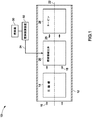
次に図面に転じると、また図1を参照すると、本技術によるガスタービン装置10の例示的な実施形態を概略的に示している。例示的な実施形態に関連する以下の説明及び特許請求の範囲が本明細書で説明する実施形態に限定されるものではないことは、注目に値する。ガスタービン装置10は、該ガスタービン装置10の様々な内部構成要素を保護しかつそれらを固定する外側ケーシング12を含む。加えて、以下でさらに説明するように、外側ケーシング12は、ガスタービン装置10に対して空気流を導く構造体を形成する。
Turning now to the drawings and referring to FIG. 1, an exemplary embodiment of a
空気流を発生させるために、この例示的なガスタービン装置10は、圧縮機14を含む。作動中、圧縮機14は、ガスタービン装置10を囲む大気から空気16を吸込み、次に空気16を装置の下流方向に強制的に流す。その結果、圧縮機は、空気の圧力を増大させる。換言すれば、圧縮機14は、環境内の空気16を加圧し、従ってその圧力を増大させて加圧空気18及び空気流を生成する。圧縮機14は、以下でさらに説明するように、装置、具体的には燃焼器を通過する加圧空気の供給源として作用する。実例を挙げれば、圧縮機14は、30倍及びそれ以上ほど空気16の圧力を増大させることができる。
In order to generate an air flow, the exemplary
加圧空気18は、下流方向に装置内に及びガスタービン装置10の長手方向軸線22の周りで同軸に配置された複数の燃焼器組立体20(すなわち、缶型燃焼器)内に導かれる。図示するように、燃焼器組立体20は、他の形状も考えられるが、ほぼ円筒形状を有する。以下でさらに説明するように、燃焼器組立体20は、加圧空気18及び燃料24を受け、燃料空気混合気の形成を可能にする。次に、燃焼器組立体20は、燃料空気混合気に点火して、排出ガス又は燃焼ガス26を形成し、この排出ガス又は燃焼ガス26がタービン28を駆動する。この例示的な装置では、複数の燃焼器組立体20のための燃料24は、燃料源30によって供給される。実例として挙げれば、燃料源30は、様々な燃焼器組立体に燃料を導く燃料マニホールドである。燃料源30(すなわち、燃料マニホールド)は、燃料制御装置32の制御下にある。この例示的な実施形態では、燃焼器組立体20の様々な構成要素への燃料24の供給は、例えばバルブシステムを使用して個別に制御される。従って、所望の量の燃料を、所望の時間にかつ互いに独立した方法で燃焼器組立体20の様々な構成要素に供給することができる。
Pressurized
複数の燃焼器組立体20内で形成された後に、燃焼ガス26は、タービン28を通って流れ、この流れによりタービン28を駆動する。タービン28の回転は、例えば発電機のロータを回転させそれによって発電するために利用するのに好都合である。これに代えて、タービン28の回転は、機械要素を駆動するために利用することもできる。
After being formed in the plurality of
図2は、本技術の例示的な実施形態による単段閉込め渦式燃焼器組立体34の部分概略断面図である。より具体的には、図2は、上に図1で説明した燃焼器組立体20の1つに類似した燃焼器缶又は燃焼器組立体34の一部分の詳細を示す。上記の説明を続けると、燃料源30及び燃料制御装置32は、燃焼器組立体の様々な分配機構及び空気混和室内に燃料24を導く。燃料24は、プロパン、天然ガス、水素又は合成ガスのような幾つかの可能な燃料源の1つとすることができ、窒素、蒸気又は二酸化炭素(CO2)のような希釈剤を含むことができる。当然、他の種類の燃料もまた考えられる。この例示的な実施形態では、燃料24は、燃焼器組立体34の拡散室36、主予混合室(すなわち、第1の予混合室38)及び二次予混合室(すなわち、第2の予混合室40)に供給される。次に、これらの領域は、以下でさらに説明するように、燃焼室42に適切な燃料又は燃料空気混合気を供給する。
FIG. 2 is a partial schematic cross-sectional view of a single stage confined
燃料24は、他の通路の中で特に、拡散室36を通して燃焼室42に供給される。拡散室36の複数の入口管44からの燃料24は、複数の開口48を介して燃焼室42の二次燃焼ゾーン又は第2の燃焼ゾーン46内に導入される。複数の開口48を通しての拡散燃料24の供給は、燃焼室42を形成する表面に対しての温度勾配を最小にする利点があると思われる。以下でさらに説明するように、拡散室36からの燃料24は、燃焼室42内における燃料空気混合気の濃厚度を、そのような濃厚度が望ましい場合及び/又はそのような状態が許される場合に増大させるのを可能にする。
この例示的な燃焼器組立体34では、導入燃料24の幾らかの部分は、燃焼室42内に加えられる前に、空気混和される。例えば、燃料24は、主予混合室38の複数の入口管50を通って流れる。この空気混和は、第1の予混合装置52内で少なくとも部分的に起こる。以下でさらに説明するように、予混合装置52は、空気及び燃料24を混合して、燃料空気混合気を生成する。燃料24を空気混和させるために、圧縮機14(図1を参照)に源を発した加圧空気は、空気流室56を通って流れ、次いで2つの部分、すなわち第1の空気流部分58及び第2の空気流部分60に分流される。加圧空気の第1の空気流部分58は、主予混合室38に流入する。予混合装置52は、燃料24の空気混和を可能にし、換言すれば、予混合装置52は、燃料24及び第1の空気流部分58を混合して、第1の燃空比を有する主燃料空気混合気又は第1の燃料空気混合気62を生成するのを可能にする。一旦混合されると、第1の空気流部分58の流れは、主燃料空気混合気62を複数の開口64に向かって押流し、次に燃焼室42内に押流す。具体的には、複数の開口64は、燃焼室42の中心に向けて設置されており、これもまた燃焼室42の中心に向けて設置された該燃焼室42の主燃焼ゾーン又は第1の燃焼ゾーン66内に燃料供給する。この例示的な実施形態では、主予混合室38からの燃料空気混合気は、比較的希薄な混合気である。
In this
この例示的な燃焼器組立体34はまた、二次空気混和領域、すなわち第2の予混合室40を含む。燃料24は、複数の燃料管68によって二次予混合室40に供給される。上に説明したように、加圧空気は、空気流室56を通って流れ、加圧空気の第2の空気流部分60は次に、二次予混合室40に流入する。主予混合装置52と同様な方法で、第2の予混合装置70は、燃料24及び第2の空気流部分60を混合して、第2の燃空比を有する二次燃料空気混合気又は第2の燃料空気混合気72を生成するのを可能にする。この例示的な実施形態では、第2の燃料空気混合気72は、主予混合室38内で生成された第1の燃料空気混合気62よりも高い燃空比を有する。つまり、二次予混合室40内で生成された燃料空気混合気72は、主予混合室38内で生成された燃料空気混合気よりも濃厚である。加圧空気60は、空気流を押進め、この空気流は、複数の開口74を通して燃料空気混合気72を燃焼室42の二次燃焼ゾーン46内に押込む。具体的には、第2の燃料空気混合気72は、主燃焼ゾーン66の半径方向外側寄りに位置する二次燃焼ゾーン46内に導入される。二次燃料空気混合気の流れと二次予混合ゾーンの設計により、逆火を防止することが可能になる。逆火は、それによって火炎が所望の方向とは反対の方向に移動する、つまり火炎が燃焼室から予混合室に向かって移動することになるプロセスである。
The
第2の燃料空気混合気72が、燃焼室内に、具体的には二次燃焼ゾーン46内に導入された時に、第2の燃料空気混合気72は渦状の状態で移動し始める。この例示的な燃焼器組立体では、導入混合気(すなわち、第2の燃料空気混合気72)は、U字形状二次燃焼ゾーン46内部に閉込められ、このU字形状により、渦流76が発生する。例えば、入口74から導入された燃料空気混合気72は、二次燃焼ゾーン46を横切って軸方向に移動し、対向する側壁に衝突して、第2の燃料空気混合気72が入口74に向かって戻るように移動する。より多くの燃料空気混合気72が入口74から導入されるにつれて、このプロセスは繰り返され、渦流76が持続する。この例示的な組立体は、二次燃焼ゾーン46内での渦流の発生を可能にする開口78を含む利点がある。その上、以下でさらに説明するように、渦流を受ける燃料空気混合気の燃空比は、拡散室36及びその対応する入口44を通して燃料24を導入することによって増大させることができる。
When the second fuel-
この例示的な燃焼器組立体34では、予混合室38、40及び拡散室36は、エンドプレート組立体80によって燃焼室42から分離される。エンドプレート組立体80は、燃焼室42と主予混合室38、拡散室36及び二次予混合室40との間に配置された第1のディスク82と、第1のディスク82を囲む第2のディスク84とを含む。この例示的な実施形態では、第1及び第2のディスクの材料は互いに異なるもとして、以下でさらに説明するように、異なる作動環境に最も適した材料となるようにする。例えば、この例示的な燃焼器では、第1のディスク82の構造は、燃焼室におけるより高い燃焼温度に適応するように、より堅牢である。
In the
作動中、特にガスタービン装置の始動時には、拡散室36を通る燃料24は、燃焼室42の二次燃焼ゾーン46内に導入され、燃焼室壁88の上方に取付けられた第1の点火装置86によって点火される。これに代えて、いくつかの実施形態では、燃焼器組立体は、各燃焼器組立体内に点火装置の代わりにクロスファイヤ管を含むことができる。クロスファイヤ管は、燃料の点火による火炎を1つの燃焼器組立体から別の燃焼器組立体に伝える管である。いずれにしても、燃料は点火源によって点火される。次に、二次燃料空気混合気72は、二次燃焼ゾーン46内に導入される。上で説明したように、二次燃焼ゾーン46のU字形状は、二次燃焼ゾーン46内部に燃料空気混合気の渦流76を形成する。この渦流は、拡散室36からの燃料24及び二次燃料空気混合気72を混合して未燃焼燃料及び燃料空気混合気を含むことができる火炎及び燃焼生成物を生成するのを可能にする利点がある。しかしながら、拡散室36から燃料24を加えることは任意選択的であることは、注目に値する。いずれにしても、点火装置86(又は、点火源)は、上で説明のように、二次燃焼ゾーン46内で渦流を受ける燃料に点火する。燃焼室42では、点火した燃料空気混合気は、主燃焼ゾーン66内に伝播し、より希薄な混合気である主燃料空気混合気62に点火する火炎及び燃焼生成物90を生成すると思われる。火炎90は、主燃焼ゾーン66内における燃料空気混合気に対するパイロットとして作用する。この火炎は、主燃料空気混合気のより安定した燃焼をもたらすものと考えられ、従って、火炎は、燃焼組立体の希薄かつ安定した作動を可能にし、それによって例えば燃焼中に発生するNOxエミッションを低減するのを可能にする。さらに、混合生成物90は、主燃焼ゾーンに流入して、主燃焼ゾーン内の燃料空気混合気に影響を与える。
During operation, particularly when starting the gas turbine system,
拡散室36、主予混合マニホールド38及び二次予混合マニホールド40への燃料24の流量は、燃料空気混合気の質及び量が特定の用途に対して望ましい状態に変更されるように制御する利点がある。例えば、ガスタービン装置の始動の間には、拡散室36を通る燃料24は、燃焼室42に供給されかつ点火される。その後徐々に二次予混合室40からの二次燃料空気混合気72が、燃焼室に導入されて該燃焼室内部の燃料24と混合される。拡散室36を通る燃料24の点火による火炎は、二次予混合室40を通って流入する濃厚な燃料空気混合気72に点火する。安定化すると、拡散室36を通る燃料24の供給を徐々に減少させ、二次予混合室40を通る二次燃料空気混合気72の流量を徐々に増大させる。
Advantages of controlling the flow rate of the
同様に、希薄な燃料空気混合気は、NOxエミッションを低減する利点がある。従って、主予混合室38の希薄な燃料空気混合気62は、燃焼室42内に導入され、二次燃焼ゾーン46により発生した火炎を使用して点火される。燃料の量を制御することによって、ガスタービン装置を有効に作動させるための様々な基準を達成することができる。燃焼室42における(二次及び主燃焼ゾーン両方内での)燃焼は、タービンに向かって流れる第1の燃焼ガス92をもたらす。燃焼室壁96上の複数の開口94及びディスク100は、燃焼室42内への空気流を可能にし、そのことが次に、NOxのエミッションを低減するのを可能にする。加えて、燃焼室壁88及び96は、衝突層102を含む。衝突層102は、燃焼室外部壁に対して加圧空気を流すのを可能にし、それによって次に燃焼室壁を冷却するのを可能にする複数の孔を有する。
Similarly, a lean fuel-air mixture has the advantage of reducing NOx emissions. Accordingly, the lean fuel-
図3は、本技術の例示的な実施形態による2段閉込め渦式燃焼器組立体104の部分概略断面図である。2段閉込め渦式燃焼器組立体104は、第2段閉込め渦式燃焼器組立体106に結合された図2の第1段閉込め渦式燃焼器組立体34を含む。第2段閉込め渦式燃焼器組立体106は、燃焼ガス室108、第3の予混合室110及び下流燃焼室112を含む。第2段閉込め渦式燃焼器組立体は、タービン入口に比較的近接して設置されてNOxエミッションの低減を向上させるのを可能にする利点がある。
FIG. 3 is a partial schematic cross-sectional view of a two-stage confined
第1段閉込め渦式燃焼器組立体34からの第1の燃焼ガス92は、第2段閉込め渦式燃焼器組立体106に向かって流れる。これらの燃焼ガス92は、エンドプレート116内の開口114を通って下流燃焼室112内に流入する。
The
上で説明したように、第2段燃焼器組立体106はまた、第3の予混合室110を含む。燃料源30及び燃料制御装置32は、第3の予混合室110の入口管120に燃料24を供給する。加圧空気122は、空気室124を通って流れ、第3の予混合室110に流入する。上で説明したように、第3の予混合装置128は、燃料24及び加圧空気122を混合して第3の燃空比を有する第3の燃料空気混合気130を生成するのを可能にする。この燃料空気混合気130は次に、複数の開口134を通して燃焼室112の第3の燃焼ゾーン132内に強制的に流される。
As described above, the second
作動中、第1段燃焼器組立体と同様に、燃料空気混合気130は、第3の燃焼ゾーン132内に流れる。燃焼室壁137に結合された第2の点火装置136(すなわち、点火源)は、第2段燃焼室112の燃焼ゾーン132内において燃料空気混合気130に点火する。上で説明したように、点火源は、点火装置又はクロスファイヤ管を含むことができる。燃料空気混合気130の点火は、燃焼ガス138をもたらす。上に図2で説明したように、この燃焼ゾーン132のU字形状は、燃焼ガス138の渦流140を可能にする。この渦流は、結果的に第2段燃焼器組立体の燃焼室112内部で燃焼ガス138を第1の燃焼ガス92と混合して第2の燃焼ガス142を生成するのを可能にする。上で説明したように、燃焼室壁146内に設けられた複数の開口144とディスク150とは、結果としてNOxのエミッションを低減する空気流を可能にする。燃焼室壁137及び146にはまた、衝突層152が設けられる。上で説明したように、衝突層152は、燃焼室壁の外面に沿った空気の流れを可能にして、そのことが次に、燃焼室壁を冷却することを可能にする。燃焼器組立体内の段数は、2つに限定されるものではない。いくつかの実施形態では、燃焼器組立体は、所望なだけの多くの段数を含むことができる。
In operation, similar to the first stage combustor assembly, the
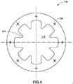
図4は、図3の第2段閉込め渦式燃焼室のエンドプレート116の正面図である。エンドプレート116は、第2段燃焼器組立体106の燃焼室112に向かって第1の燃焼ガス混合気92が自由に流れるのを可能にする開口114を含む。当業者には明らかなように、第1段燃焼室42からの燃焼ガス92の温度は比較的高く、エンドプレート116は、これらの燃焼ガス92に適応して損傷の可能性を軽減させるようにする必要がある。従って、開口114は、該開口114が第2段燃焼器組立体106の燃焼室112に向かって燃焼ガス92が自由に流れるのを可能にしながら、同時に燃料空気混合気130の点火による火炎及び燃焼ガス138と第1の燃焼ガス92との混合にも有利になるような方法で、設計される。実際には、この例示的なエンドプレートは、燃焼室112内での火炎及び燃焼生成物138と燃焼ガス92との混合を部分的に可能にするフィンガ117を含む。図示するように、これらのフィンガ117は、エンドプレート116の渦巻き形の内面によって少なくともその一部が形成される。
FIG. 4 is a front view of the
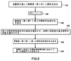
図2を念頭に置いて、図5は、本技術の様態による、ガスタービンの単段燃焼器組立体内における希薄かつ安定した燃焼用燃料空気混合気を確立するための例示的なプロセスを示すフローチャートである。本プロセスは、ステップ154で表わすように、ガスタービン装置を始動するために拡散室36を通して燃焼室42に燃料24を送る段階を含む。ステップ156で表わすように、点火装置86は、燃料24に点火して、燃焼生成物92を生成する。次に、燃料空気混合気72は、該燃料空気混合気72が燃焼室42内部で渦流76を形成するような方法で、燃焼室42内に送られる。ステップ158で表わすように、この渦流76は、燃料空気混合気72を拡散室36を通る燃料24と混合して、火炎及び燃焼生成物90を生成するのを可能にする。ステップ160で表わすように、二次予混合室からの燃料空気混合気72の流量を徐々に増加させ、拡散室36からの燃料24の流量を徐々に減少させる。本プロセスはさらに、ステップ162で表わすように、主予混合室38を通して燃焼室42に主燃料空気混合気62を導入する段階を含む。上で説明したように、二次燃焼ゾーン内における火炎及び燃焼生成物90の渦流76はまた、ステップ164で表わすように、主燃焼ゾーン66内で主燃料空気混合気62に点火して燃焼ガス92を生成するのを可能にする。
With FIG. 2 in mind, FIG. 5 is a flowchart illustrating an exemplary process for establishing a lean and stable combustion fuel-air mixture in a single stage combustor assembly of a gas turbine according to an aspect of the present technology. It is. The process includes delivering
図3を念頭に置いて、図6は、本技術の様態による、ガスタービンの2段燃焼器組立体内における希薄かつ安定した燃焼用燃料空気混合気を確立するための例示的プロセスを示すフローチャートである。本プロセスは、第1段燃焼器組立体34の燃焼室42内で希薄な燃料空気混合気62に点火して第1の燃焼ガス92を発生させる段階を含む。本プロセスはさらに、ステップ166で表わすように、第1段燃焼器組立体34の燃焼室から第2段燃焼器組立体106の燃焼室112に燃焼ガス92を送る段階を含む。さらに、ステップ168で表わすように、第2段燃焼器組立体106の予混合室110内で生成された燃料空気混合気130は、該燃料空気混合気130が燃焼室112の内部で渦流140を形成するような方法で、燃焼室112に送られる。ステップ170で表わすように、第2の点火装置136は、燃焼室112内部で燃料空気混合気130に点火して、火炎及び燃焼ガス138を生成する。ステップ172で表わすように、渦流140は、燃焼ガス138を第1の燃焼ガス92と混合して第2の燃焼ガス142を生成するのを可能にする。ステップ174で表わすように、第2段燃焼器組立体106の燃焼室112からの燃焼ガス142は次に、タービンに送られてタービンを作動させる。
With FIG. 3 in mind, FIG. 6 is a flowchart illustrating an exemplary process for establishing a lean and stable combustion fuel-air mixture in a two-stage combustor assembly of a gas turbine according to an aspect of the present technology. is there. The process includes igniting a lean fuel-
本明細書では本発明の一部の特徴のみを図示かつ説明してきたが、当業者は多くの修正及び変更に想到するであろう。特許請求の範囲に記載した参照符号は、本発明の技術的範囲を狭めるためのものではなく、それらを容易に理解するためのものである。 While only certain features of the invention have been illustrated and described herein, many modifications and changes will occur to those skilled in the art. Reference numerals in the claims are not intended to narrow the technical scope of the present invention but to facilitate understanding thereof.
24 燃料
34 燃焼器組立体
36 拡散室
38 第1の予混合室
40 第2の予混合室
42 燃焼室
46 第2の燃焼ゾーン
58、60 空気
62 第1の燃料空気混合気
66 第1の燃焼ゾーン
72 第2の燃料空気混合気
76 渦流
80 エンドプレート組立体
86 点火源
90 火炎及び燃焼ガス
92 第1の燃焼ガス
96 燃焼室の壁
102 衝突層
24
Claims (10)
第1の燃焼ゾーン(66)と第2の燃焼ゾーン(46)とを有する燃焼室(42)と、
燃料(24)及び空気(58)を受けて第1の燃空比を有する第1の燃料空気混合気(62)を可能にするように構成されかつ前記第1の燃焼ゾーン(66)において前記燃焼室(42)に流体的に結合された第1の予混合室(38)と、
燃料(24)及び空気(60)を受けて第2の燃空比を有する第2の燃料空気混合気(72)を可能にするように構成されかつ前記第1の燃焼ゾーン(66)の半径方向外側寄りに位置する第2の燃焼ゾーン(46)において前記燃焼室(42)に流体的に結合された第2の予混合室(40)と、
を含む燃焼器組立体。 A combustor assembly (34) for use in a gas turbine device comprising:
A combustion chamber (42) having a first combustion zone (66) and a second combustion zone (46);
Configured to receive a fuel (24) and air (58) to allow a first fuel-air mixture (62) having a first fuel-air ratio and in the first combustion zone (66) A first premixing chamber (38) fluidly coupled to the combustion chamber (42);
Configured to receive a fuel (24) and air (60) to enable a second fuel-air mixture (72) having a second fuel-air ratio and a radius of the first combustion zone (66) A second premixing chamber (40) fluidly coupled to the combustion chamber (42) in a second combustion zone (46) located outwardly in the direction;
A combustor assembly.
燃焼器組立体(34)の第1の予混合室(38)に燃料(24)及び加圧空気(58)を供給する段階と、
前記第1の予混合室(38)内において前記供給燃料(24)及び加圧空気(58)によって第1の燃空比を有する第1の燃料空気混合気(62)を生成する段階と、
前記燃焼器組立体(34)の燃焼室(42)の第1の燃焼ゾーン(66)に前記第1の燃料空気混合気(62)を送る段階と、
前記燃焼器組立体(34)の第2の予混合室(40)に燃料(24)及び加圧空気(60)を供給する段階と、
前記第2の予混合室(40)内において前記供給燃料(24)及び加圧空気(60)によって第2の燃空比を有する第2の燃料空気混合気(72)を生成する段階と、
前記第1の燃焼ゾーン(66)の半径方向外側寄りに配置された、前記燃焼器組立体(34)の燃焼室(42)の第2の燃焼ゾーン(46)に前記第2の燃料空気混合気(72)を送る段階と、
前記第2の燃焼ゾーン(46)内に前記第2の燃料空気混合気(72)の渦流(76)を発生させる段階と、
を含む方法。 A method of supplying combustion gas (92) for a gas turbine device comprising:
Supplying fuel (24) and pressurized air (58) to the first premixing chamber (38) of the combustor assembly (34);
Generating a first fuel-air mixture (62) having a first fuel-air ratio with the supplied fuel (24) and pressurized air (58) in the first premixing chamber (38);
Sending the first fuel-air mixture (62) to a first combustion zone (66) of a combustion chamber (42) of the combustor assembly (34);
Supplying fuel (24) and pressurized air (60) to a second premixing chamber (40) of the combustor assembly (34);
Generating a second fuel-air mixture (72) having a second fuel-air ratio with the supplied fuel (24) and pressurized air (60) in the second premixing chamber (40);
The second fuel-air mixture in the second combustion zone (46) of the combustion chamber (42) of the combustor assembly (34), located radially outward of the first combustion zone (66). Sending qi (72);
Generating a swirl (76) of the second fuel-air mixture (72) in the second combustion zone (46);
Including methods.
Applications Claiming Priority (1)
| Application Number | Priority Date | Filing Date | Title |
|---|---|---|---|
| US10/994,833 US20060107667A1 (en) | 2004-11-22 | 2004-11-22 | Trapped vortex combustor cavity manifold for gas turbine engine |
Publications (2)
| Publication Number | Publication Date |
|---|---|
| JP2006145194A true JP2006145194A (en) | 2006-06-08 |
| JP2006145194A5 JP2006145194A5 (en) | 2008-09-04 |
Family
ID=35562442
Family Applications (1)
| Application Number | Title | Priority Date | Filing Date |
|---|---|---|---|
| JP2005210786A Withdrawn JP2006145194A (en) | 2004-11-22 | 2005-07-21 | Trapped vortex combustor cavity manifold for gas turbine engine |
Country Status (4)
| Country | Link |
|---|---|
| US (1) | US20060107667A1 (en) |
| EP (1) | EP1659338A1 (en) |
| JP (1) | JP2006145194A (en) |
| CN (1) | CN1779328A (en) |
Cited By (2)
| Publication number | Priority date | Publication date | Assignee | Title |
|---|---|---|---|---|
| JP2010506131A (en) * | 2006-10-06 | 2010-02-25 | ゼネラル・エレクトリック・カンパニイ | Combustor nozzle for fuel flexible combustion system |
| JP2013504733A (en) * | 2009-09-13 | 2013-02-07 | リーン フレイム インコーポレイテッド | Inlet premixer for combustion equipment |
Families Citing this family (24)
| Publication number | Priority date | Publication date | Assignee | Title |
|---|---|---|---|---|
| US7603841B2 (en) * | 2001-07-23 | 2009-10-20 | Ramgen Power Systems, Llc | Vortex combustor for low NOx emissions when burning lean premixed high hydrogen content fuel |
| JP2007113888A (en) * | 2005-10-24 | 2007-05-10 | Kawasaki Heavy Ind Ltd | Combustor structure of gas turbine engine |
| US20070204624A1 (en) * | 2006-03-01 | 2007-09-06 | Smith Kenneth O | Fuel injector for a turbine engine |
| EP1890083A1 (en) * | 2006-08-16 | 2008-02-20 | Siemens Aktiengesellschaft | Fuel injector for a gas turbine engine |
| US8015814B2 (en) * | 2006-10-24 | 2011-09-13 | Caterpillar Inc. | Turbine engine having folded annular jet combustor |
| US8011188B2 (en) * | 2007-08-31 | 2011-09-06 | General Electric Company | Augmentor with trapped vortex cavity pilot |
| WO2010096817A2 (en) * | 2009-02-23 | 2010-08-26 | Williams International Co., L.L.C. | Combustion system |
| US20100285413A1 (en) * | 2009-05-06 | 2010-11-11 | General Vortex Energy, Inc. | Apparatus and Methods For Providing Uniformly Volume Distributed Combustion of Fuel |
| US20110131998A1 (en) * | 2009-12-08 | 2011-06-09 | Vaibhav Nadkarni | Fuel injection in secondary fuel nozzle |
| EP2423591B1 (en) * | 2010-08-24 | 2018-10-31 | Ansaldo Energia IP UK Limited | Method for operating a combustion chamber |
| US20120144832A1 (en) * | 2010-12-10 | 2012-06-14 | General Electric Company | Passive air-fuel mixing prechamber |
| US9140455B2 (en) * | 2012-01-04 | 2015-09-22 | General Electric Company | Flowsleeve of a turbomachine component |
| US9074773B2 (en) * | 2012-02-07 | 2015-07-07 | General Electric Company | Combustor assembly with trapped vortex cavity |
| US9297533B2 (en) * | 2012-10-30 | 2016-03-29 | General Electric Company | Combustor and a method for cooling the combustor |
| US9383098B2 (en) * | 2012-10-31 | 2016-07-05 | General Electric Company | Radial flow fuel nozzle for a combustor of a gas turbine |
| CA2931355A1 (en) | 2013-11-25 | 2015-05-28 | Entech - Renewable Energy Solutions Pty.Ltd. | Apparatus for firing and combustion of syngas |
| US20150159877A1 (en) * | 2013-12-06 | 2015-06-11 | General Electric Company | Late lean injection manifold mixing system |
| US9803555B2 (en) * | 2014-04-23 | 2017-10-31 | General Electric Company | Fuel delivery system with moveably attached fuel tube |
| US10184664B2 (en) * | 2014-08-01 | 2019-01-22 | Capstone Turbine Corporation | Fuel injector for high flame speed fuel combustion |
| US10072846B2 (en) * | 2015-07-06 | 2018-09-11 | General Electric Company | Trapped vortex cavity staging in a combustor |
| EP3450850A1 (en) * | 2017-09-05 | 2019-03-06 | Siemens Aktiengesellschaft | A gas turbine combustor assembly with a trapped vortex cavity |
| US11156164B2 (en) | 2019-05-21 | 2021-10-26 | General Electric Company | System and method for high frequency accoustic dampers with caps |
| US11174792B2 (en) | 2019-05-21 | 2021-11-16 | General Electric Company | System and method for high frequency acoustic dampers with baffles |
| US11846426B2 (en) * | 2021-06-24 | 2023-12-19 | General Electric Company | Gas turbine combustor having secondary fuel nozzles with plural passages for injecting a diluent and a fuel |
Family Cites Families (18)
| Publication number | Priority date | Publication date | Assignee | Title |
|---|---|---|---|---|
| DE2937631A1 (en) * | 1979-09-18 | 1981-04-02 | Daimler-Benz Ag, 7000 Stuttgart | COMBUSTION CHAMBER FOR GAS TURBINES |
| US5359847B1 (en) * | 1993-06-01 | 1996-04-09 | Westinghouse Electric Corp | Dual fuel ultra-flow nox combustor |
| JP2950720B2 (en) * | 1994-02-24 | 1999-09-20 | 株式会社東芝 | Gas turbine combustion device and combustion control method therefor |
| US5857339A (en) * | 1995-05-23 | 1999-01-12 | The United States Of America As Represented By The Secretary Of The Air Force | Combustor flame stabilizing structure |
| US5619855A (en) * | 1995-06-07 | 1997-04-15 | General Electric Company | High inlet mach combustor for gas turbine engine |
| US5791148A (en) * | 1995-06-07 | 1998-08-11 | General Electric Company | Liner of a gas turbine engine combustor having trapped vortex cavity |
| US5647215A (en) * | 1995-11-07 | 1997-07-15 | Westinghouse Electric Corporation | Gas turbine combustor with turbulence enhanced mixing fuel injectors |
| DE19614001A1 (en) * | 1996-04-09 | 1997-10-16 | Abb Research Ltd | Combustion chamber |
| US6295801B1 (en) * | 1998-12-18 | 2001-10-02 | General Electric Company | Fuel injector bar for gas turbine engine combustor having trapped vortex cavity |
| US6286298B1 (en) * | 1998-12-18 | 2001-09-11 | General Electric Company | Apparatus and method for rich-quench-lean (RQL) concept in a gas turbine engine combustor having trapped vortex cavity |
| US6286317B1 (en) * | 1998-12-18 | 2001-09-11 | General Electric Company | Cooling nugget for a liner of a gas turbine engine combustor having trapped vortex cavity |
| US6609376B2 (en) * | 2000-02-14 | 2003-08-26 | Ulstein Turbine As | Device in a burner for gas turbines |
| US6481209B1 (en) * | 2000-06-28 | 2002-11-19 | General Electric Company | Methods and apparatus for decreasing combustor emissions with swirl stabilized mixer |
| US6334298B1 (en) * | 2000-07-14 | 2002-01-01 | General Electric Company | Gas turbine combustor having dome-to-liner joint |
| EP1255080B1 (en) * | 2001-04-30 | 2008-09-03 | ALSTOM Technology Ltd | Catalytic burner |
| GB0111788D0 (en) * | 2001-05-15 | 2001-07-04 | Rolls Royce Plc | A combustion chamber |
| US7003961B2 (en) * | 2001-07-23 | 2006-02-28 | Ramgen Power Systems, Inc. | Trapped vortex combustor |
| US6735949B1 (en) | 2002-06-11 | 2004-05-18 | General Electric Company | Gas turbine engine combustor can with trapped vortex cavity |
-
2004
- 2004-11-22 US US10/994,833 patent/US20060107667A1/en not_active Abandoned
-
2005
- 2005-07-08 EP EP05254296A patent/EP1659338A1/en not_active Withdrawn
- 2005-07-21 JP JP2005210786A patent/JP2006145194A/en not_active Withdrawn
- 2005-07-22 CN CN200510087541.3A patent/CN1779328A/en active Pending
Cited By (3)
| Publication number | Priority date | Publication date | Assignee | Title |
|---|---|---|---|---|
| JP2010506131A (en) * | 2006-10-06 | 2010-02-25 | ゼネラル・エレクトリック・カンパニイ | Combustor nozzle for fuel flexible combustion system |
| KR101443929B1 (en) | 2006-10-06 | 2014-09-23 | 제너럴 일렉트릭 캄파니 | Combustor nozzle for a fuel-flexible combustion system |
| JP2013504733A (en) * | 2009-09-13 | 2013-02-07 | リーン フレイム インコーポレイテッド | Inlet premixer for combustion equipment |
Also Published As
| Publication number | Publication date |
|---|---|
| EP1659338A1 (en) | 2006-05-24 |
| US20060107667A1 (en) | 2006-05-25 |
| CN1779328A (en) | 2006-05-31 |
Similar Documents
| Publication | Publication Date | Title |
|---|---|---|
| JP2006145194A (en) | Trapped vortex combustor cavity manifold for gas turbine engine | |
| JP2713627B2 (en) | Gas turbine combustor, gas turbine equipment including the same, and combustion method | |
| JP5364275B2 (en) | Method and system for enabling NOx emissions to be reduced in a combustion system | |
| US6826913B2 (en) | Airflow modulation technique for low emissions combustors | |
| US5850731A (en) | Catalytic combustor with lean direct injection of gas fuel for low emissions combustion and methods of operation | |
| JP4658471B2 (en) | Method and apparatus for reducing combustor emissions in a gas turbine engine | |
| US7513115B2 (en) | Flashback suppression system for a gas turbine combustor | |
| JP2007139411A (en) | Low emission combustor and method for operating it | |
| JP7044669B2 (en) | Gas turbine combustor | |
| KR20150065782A (en) | Combustor with radially staged premixed pilot for improved operability | |
| EP2244014B1 (en) | Radial lean direct injection burner | |
| US20100281876A1 (en) | Fuel blanketing by inert gas or less reactive fuel layer to prevent flame holding in premixers | |
| KR20090127046A (en) | Coanda pilot nozzle for low emission combustors | |
| JP2009047410A (en) | Method and device for burning fuel in gas turbine engine | |
| KR20100080428A (en) | Dln dual fuel primary nozzle | |
| JP2009250604A (en) | Burner tube premixer and method for mixing air with gas in gas turbine engine | |
| JP2011002221A (en) | A plurality of fuel circuits for synthesis gas/natural gas dry type low nox in premixing nozzle | |
| KR20150063507A (en) | Method of operating a multi-stage flamesheet combustor | |
| JP4882422B2 (en) | Gas turbine combustor and combustion method of combustion apparatus | |
| KR20140082659A (en) | Can-annular combustor with premixed tangential fuel-air nozzles for use on gas turbine engines | |
| JP4916311B2 (en) | Pilot combustion system that stabilizes combustion in gas turbine engines | |
| JP2003074856A (en) | Combustion equipment of gas-turbine engine | |
| JP4854613B2 (en) | Combustion apparatus and gas turbine combustor | |
| JP3139978B2 (en) | Gas turbine combustor | |
| JP2003074853A (en) | Combustion equipment of gas-turbine engine |
Legal Events
| Date | Code | Title | Description |
|---|---|---|---|
| A521 | Request for written amendment filed |
Free format text: JAPANESE INTERMEDIATE CODE: A523 Effective date: 20080717 |
|
| A621 | Written request for application examination |
Free format text: JAPANESE INTERMEDIATE CODE: A621 Effective date: 20080717 |
|
| A761 | Written withdrawal of application |
Free format text: JAPANESE INTERMEDIATE CODE: A761 Effective date: 20091029 |