RU2417153C2 - Method of closing container by cover and device to this end - Google Patents
Method of closing container by cover and device to this end Download PDFInfo
- Publication number
- RU2417153C2 RU2417153C2 RU2009129566/12A RU2009129566A RU2417153C2 RU 2417153 C2 RU2417153 C2 RU 2417153C2 RU 2009129566/12 A RU2009129566/12 A RU 2009129566/12A RU 2009129566 A RU2009129566 A RU 2009129566A RU 2417153 C2 RU2417153 C2 RU 2417153C2
- Authority
- RU
- Russia
- Prior art keywords
- cover
- air
- lid
- container
- pneumatic cylinders
- Prior art date
Links
- 238000000034 method Methods 0.000 title claims abstract description 21
- 125000004122 cyclic group Chemical group 0.000 claims description 3
- 230000001360 synchronised effect Effects 0.000 claims description 3
- 230000000694 effects Effects 0.000 abstract description 2
- 239000000126 substance Substances 0.000 abstract 1
- 238000007789 sealing Methods 0.000 description 4
- 238000002844 melting Methods 0.000 description 3
- 230000008018 melting Effects 0.000 description 3
- 101100508883 Bacillus subtilis (strain 168) iolI gene Proteins 0.000 description 2
- 238000003825 pressing Methods 0.000 description 2
- 238000005096 rolling process Methods 0.000 description 2
- 238000010521 absorption reaction Methods 0.000 description 1
- 238000010586 diagram Methods 0.000 description 1
- 230000010355 oscillation Effects 0.000 description 1
- 238000002604 ultrasonography Methods 0.000 description 1
Images
Landscapes
- Filling Or Discharging Of Gas Storage Vessels (AREA)
- Closing Of Containers (AREA)
Abstract
Description
Область техники, к которой относятся изобретенияFIELD OF THE INVENTION
Изобретения относятся к способам и устройствам закрывания тары (банки) крышкой, снабженной элементами фиксации крышки на таре типа защелки, после заполнения тары продуктом путем силового прижимающего воздействия на крышку, находящуюся на горловине тары.The invention relates to methods and devices for closing a container (can) with a lid equipped with lid fixing elements on a latch type container, after filling the container with product by forceful pressing on the lid located on the neck of the container.
Уровень техникиState of the art
Известен способ закрывания тары крышкой путем плавления противоположных слоев запечатываемого материала тары и крышки при помощи ультразвуковых колебаний. Устройство, реализующее этот способ, содержит опору для поддержки ребра запечатывания, хобот, состоящий из колоннообразной части и сводчатой части, средства для прижатия данного ребра запечатывания к данной опоре посредством вершины данного хобота и для передачи ультразвуковых колебаний к ребру запечатывания, а также средство поглощения ультразвуковых колебаний, расположенное между вершиной хобота и кромкой ребра запечатывания, для поглощения ультразвуковых колебаний (патент RU №2127696, МПК6 B65B 51/22, B65B 7/16, B31B 1/66, опубликовано 20.03.1999).A known method of closing containers with a lid by melting the opposite layers of the sealed material of the container and the lid using ultrasonic vibrations. A device that implements this method includes a support for supporting the sealing rib, a trunk consisting of a columnar part and a vaulted part, means for pressing the sealing rib to the given support by the top of this trunk and for transmitting ultrasonic vibrations to the sealing rib, and an ultrasonic absorption means oscillations located between the top of the trunk and the edge of the sealing rib to absorb ultrasonic vibrations (patent RU No. 2127696, IPC6 B65B 51/22, B65B 7/16, B31B 1/66, published 03/20/1999).
Признаков известного способа и признаков известного устройства, совпадающих с признаками заявленных изобретений, нет.There are no signs of the known method and signs of the known device that match the features of the claimed inventions.
Причина, препятствующая получению в известных способах и устройстве технического результата, который обеспечивается заявленными изобретениями, заключается в использовании плавления, а также ультразвука для этого плавления.The reason that prevents obtaining in the known methods and apparatus of a technical result, which is provided by the claimed invention, is the use of melting, as well as ultrasound for this melting.
Наиболее близким аналогом (прототипом) в отношении заявленного способа является способ закрывания тары крышкой путем предварительной установки крышки на горловине тары и дальнейшего последовательного силового воздействия сверху на части крышки, так что сначала воздействуют на первую часть крышки, включающую первую часть периметра крышки, составляющую половину или менее половины ее полного периметра, затем воздействуют на вторую часть крышки, включающую ее геометрический центр, для удаления излишков воздуха из-под крышки, после этого воздействуют на третью часть крышки, противоположную первой ее части относительно ее геометрического центра и включающую вторую часть периметра крышки, составляющую половину или менее половины ее полного периметра, не включенную в первую часть крышки. При этом указанные силовые воздействия осуществляют путем прокатывания (при помощи конвейера) упомянутой тары с накинутой на нее крышкой между упорным валом конвейера, с одной стороны, и прижимными роликом с кольцом, с другой стороны (см. описание к патенту на полезную модель RU №67024, М. кл. B60B 15/00, дата публикация 10.10.2007).The closest analogue (prototype) in relation to the claimed method is a method of closing a container with a lid by pre-installing the lid on the neck of the container and then subsequently applying a force on top of the lid part, so that the first part of the lid, including the first part of the lid perimeter, which is half or less than half of its full perimeter, then act on the second part of the cover, including its geometric center, to remove excess air from under the cover, then act on the third part of the cover, opposite the first part relative to its geometric center and including the second part of the perimeter of the cover, comprising half or less than half of its full perimeter, not included in the first part of the cover. At the same time, these force effects are carried out by rolling (using a conveyor) the mentioned containers with a lid thrown on it between the thrust shaft of the conveyor, on the one hand, and the pressure roller with the ring, on the other hand (see the description of the patent for utility model RU No. 67024 , M. C. B60B 15/00,
Наиболее близким аналогом (прототипом) в отношении заявленного устройства является закрыватель крышки, содержащий раму, присоединенную к раме натяжную звездочку, ведущий и натяжной барабаны, прижимной ролик, конвейерную ленту, сниматель, упорный вал, мотор-редуктор, причем прижимной ролик выполнен с возможностью вращения синхронно с конвейерной лентой и закреплен на плите, выполненной с возможностью регулирования по высоте (тот же патент №67024).The closest analogue (prototype) with respect to the claimed device is a cover closure comprising a frame, a tension sprocket attached to the frame, a drive and tension drums, a pressure roller, a conveyor belt, a stripper, a thrust shaft, a gear motor, and the pressure roller is rotatable synchronously with the conveyor belt and mounted on a plate made with adjustable height (the same patent No. 67024).
Признаки известного способа, совпадающие с признаками заявленного изобретения (способа), заключаются в том, что крышку предварительно устанавливают на горловине тары и далее последовательно осуществляют силовое воздействие сверху на части крышки, так что сначала воздействуют на первую часть крышки, включающую первую часть периметра крышки, составляющую половину или менее половины ее полного периметра, затем воздействуют на вторую часть крышки, включающую ее геометрический центр, для удаления излишков воздуха из под крышки, после этого воздействуют на третью часть крышки, противоположную первой ее части относительно ее геометрического центра и включающую вторую часть периметра крышки, составляющую половину или менее половины ее полного периметра, не включенную в первую часть крышки.The signs of the known method, which coincides with the features of the claimed invention (method), are that the lid is pre-installed on the neck of the container and then subsequently carry out a force action from above on the lid part, so that first they act on the first part of the lid, including the first part of the lid perimeter, constituting half or less than half of its full perimeter, then act on the second part of the cover, including its geometric center, to remove excess air from under the cover, then act on the third part of the cover, opposite the first part relative to its geometric center and including the second part of the perimeter of the cover, comprising half or less than half of its full perimeter, not included in the first part of the cover.
Признаков известного устройства, совпадающих с признаками заявленного изобретения (устройства), нет.There are no signs of a known device that matches the features of the claimed invention (device).
Причина, препятствующая получению в известных способе и устройстве технического результата, который обеспечивается изобретениями, заключается в том, что необходимую последовательность силового воздействия на крышку осуществляют путем прокатывания тары с накинутой на нее крышкой между прижимным роликом и упорным валом, что усложняет способ и реализующее его устройство, так как требует применения конвейера, обеспечения синхронного вращения прижимного ролика с лентой конвейера, регулирования плиты по высоте для подстройки устройства под изменяющиеся вертикальные габариты тары.The reason that prevents obtaining a technical result in the known method and device, which is provided by the inventions, is that the necessary sequence of force action on the lid is carried out by rolling the container with the lid thrown over it between the pressure roller and the thrust shaft, which complicates the method and the device that implements it , since it requires the use of a conveyor, providing synchronous rotation of the pressure roller with a conveyor belt, adjusting the plate height to adjust the device od varying vertical dimensions of the container.
Раскрытие изобретенияDisclosure of invention
Задача, на решение которой направлены изобретения, заключается в упрощении способа закрывания тары крышкой, а также в упрощении конструкции реализующего его устройства и повышении его (устройства) надежности.The problem to which the invention is directed is to simplify the method of closing the container with a lid, as well as to simplify the design of the device that implements it and increase its reliability.
Технический результат, опосредствующий решение указанной задачи, заключается в исключении конвейера, прижимного ролика и упорного вала при сохранении тех функций, которые они выполняли в известных способе и устройстве (прототипах).The technical result that mediates the solution of this problem is to exclude the conveyor, pinch roller and thrust shaft while maintaining the functions that they performed in the known method and device (prototypes).
Достигается технический результат в заявленном способе тем, что крышку предварительно устанавливают на горловине тары и затем последовательно осуществляют силовое воздействие сверху на части крышки, так что сначала воздействуют на первую часть крышки, включающую первую часть периметра крышки, составляющую половину или менее половины ее полного периметра, затем воздействуют на вторую часть крышки, включающую ее геометрический центр, для удаления излишков воздуха из-под крышки, после этого воздействуют на третью часть крышки, противоположную первой ее части относительно ее геометрического центра и включающую вторую часть периметра крышки, составляющую половину или менее половины ее полного периметра, не включенную в первую часть крышки, при этом указанное силовое воздействие осуществляют при помощи трех поршневых пневмоцилиндров, установленных вертикально в одной плоскости над соответствующими частями крышки, для чего в одно и то же время в верхние части пневмоцилиндров, поршни которых до этого находились в крайнем верхнем положении, являющимся исходным, начинают подавать сжатый воздух с разными расходами для обеспечения движения поршней пневмоцилиндров вниз с разными скоростями, так что в первый пневмоцилиндр, шток которого расположен над первой частью крышки, воздух подают с расходом Q1, во второй пневмоцилиндр, шток которого расположен над второй частью крышки, воздух подают с расходом Q2, а в третий пневмоцилиндр, шток которого расположен над третьей частью крышки, воздух подают с расходом Q3, причем Q1>Q2>Q3, а затем через заданное время, достаточное для закрывания тары крышкой по всему периметру крышки и удаления излишков воздуха из-под нее, подачу сжатого воздуха в верхние части пневмоцилиндров прекращают, а упомянутые поршни возвращают в исходное положение.A technical result is achieved in the claimed method in that the lid is pre-installed on the neck of the container and then the force is applied sequentially from above to the lid parts, so that first they act on the first part of the lid, including the first part of the lid perimeter, which is half or less than half of its full perimeter, then they act on the second part of the lid, including its geometric center, to remove excess air from under the lid, after which they act on the third part of the lid, false of its first part relative to its geometric center and including the second part of the cover perimeter, which makes up half or less than half of its full perimeter, not included in the first part of the cover, while the specified force is carried out using three piston pneumatic cylinders mounted vertically in one plane above the corresponding parts of the cover, for which at the same time in the upper parts of the pneumatic cylinders, the pistons of which were previously in the highest position, which is the original, begin to supply compressed air at different rates to ensure that the pistons of the pneumatic cylinders move downward at different speeds, so that air is supplied to the first pneumatic cylinder, the rod of which is located above the first part of the cover, with a flow rate of Q 1 , to the second pneumatic cylinder, the rod of which is located above the second part of the cover, fed at a flow rate Q 2 and the third air cylinder, the rod of which is located on the third portion of the cover, air is supplied at a flow rate Q 3, wherein Q 1> Q 2> Q 3, and then after a specified time, sufficient to close the lid container around perimet at the lid and remove excess air from under it, the compressed air in the upper part of cylinders is stopped, and said piston is returned to its original position.
Достигается технический результат в заявленном устройстве тем, что устройство содержит стол для расположения тары, три пневмоцилиндра, установленных вертикально в одной плоскости над столом, так что второй пневмоцилиндр расположен между первым и третьим пневмоцилиндрами, а на нижних концах штоков по крайней мере первого и третьего пневмоцилиндров перпендикулярно этим штокам установлены упорные пластины, предназначенные для силового воздействия на тару, блок управления пневмоцилиндрами, выполненный с возможностью циклической и синхронной подачи сжатого воздуха в пневмоцилиндры, а также пневмодроссели, определяющие расходы воздуха при его подаче в верхние части пневмоцилиндров и имеющие условные диаметры их проходных сечений: D1 - для первого пневмопривода, D2 - для второго пневмопривода и D3 - для третьего пневмопривода, при этом D1>D2>D3.A technical result is achieved in the claimed device in that the device contains a table for arranging containers, three pneumatic cylinders mounted vertically in the same plane above the table, so that the second pneumatic cylinder is located between the first and third pneumatic cylinders, and at the lower ends of the rods at least the first and third pneumatic cylinders perpendicular to these rods mounted thrust plates designed for force impact on the container, the control unit of the pneumatic cylinders, made with the possibility of cyclic and synch onnoy supplying compressed air to the cylinders, and Unidirectional defining airflows when fed into the upper part of cylinders and having nominal sizes of flow areas: D 1 - for the first actuator, D 2 - for the second actuator, and D 3 - for a third actuator, wherein D 1 > D 2 > D 3 .
Новые признаки предлагаемого способа заключаются в том, что силовое воздействие осуществляют при помощи трех поршневых пневмоцилиндров, установленных вертикально в одной плоскости над соответствующими частями крышки, для чего в одно и то же время в верхние части пневмоцилиндров, поршни которых до этого находились в крайнем верхнем положении, являющимся исходным, начинают подавать сжатый воздух с разными расходами для обеспечения движения поршней пневмоцилиндров вниз с разными скоростями, так что в первый пневмоцилиндр, шток которого расположен над первой частью крышки, воздух подают с расходом Q1, во второй пневмоцилиндр, шток которого расположен над второй частью крышки, воздух подают с расходом Q2, а в третий пневмоцилиндр, шток которого расположен над третьей частью крышки, воздух подают с расходом Q3, причем Q1>Q2>Q3, а затем через заданное время, достаточное для закрывания тары крышкой по всему периметру крышки и удаления излишков воздуха из-под нее, подачу сжатого воздуха в верхние части пневмоцилиндров прекращают, а упомянутые поршни возвращают в исходное положение.New features of the proposed method are that the force is effected using three piston pneumatic cylinders mounted vertically in the same plane above the corresponding parts of the cap, for which at the same time in the upper parts of the pneumatic cylinders, the pistons of which were previously in their highest position , which is the source, begin to supply compressed air at different rates to ensure the movement of the pistons of the pneumatic cylinders down at different speeds, so that in the first pneumatic cylinder, the rod of which Position the above the first lid portion, air is supplied at a flow rate Q 1, the second air cylinder, the rod of which is located above the second portion of the cover, air is supplied at a flow rate Q 2 and the third air cylinder, the rod of which is located on the third portion of the cover, air is supplied at a flow rate Q 3 , with Q 1 > Q 2 > Q 3 , and then after a specified time sufficient to close the container with a lid around the entire perimeter of the lid and remove excess air from under it, the supply of compressed air to the upper parts of the pneumatic cylinders is stopped, and the mentioned pistons are returned to initial position s.
Новыми признаками заявленного устройства являются все перечисленные выше признаки устройства.New features of the claimed device are all of the above features of the device.
Краткое описание чертежейBrief Description of the Drawings
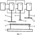
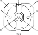
На фиг.1 показана функциональная схема устройства для закрывания тары крышкой; на фиг.2 - соединенные со штоками пневмоцилиндров упорные пластины в плане.Figure 1 shows a functional diagram of a device for closing containers with a lid; figure 2 - connected with the rods of the pneumatic cylinders thrust plates in the plan.
Осуществление изобретенийThe implementation of the invention
Устройство для закрывания тары крышкой содержит стол 1 для расположения на нем тары (банки) 2 с накинутой на ее горловину крышкой 3, три пневмоцилиндра двухстороннего действия 4, 5 и 6, установленные вертикально над столом 1 в одной плоскости, и блок управления 7, выполненный с возможностью циклической и синхронной подачи сжатого воздуха в пневмоцилиндры 4, 5 и 6. Устройство также содержит пневмодроссели (не показаны), которые установлены на выходах воздуха из пневмоцилиндров 4, 5 и 6 при движении их поршней вниз. Пневмодроссели определяют расходы воздуха при его подаче в верхние части пневмоцилиндров и имеют условные диаметры их проходных сечений D1 - для первого пневмоцилиндра, D2 - для второго пневмоцилиндра и D3 - для третьего пневмоцилиндра, при этом D1>D2>D3. Блок управления 7 выполнен в виде двухлинейного и двухпозиционного пневмораспределителя, выходы которого соединены с соответствующими входами пневмоцилиндров. Блок управления также содержит средства управления пневмораспределителем (не показаны).A device for closing the container with a lid contains a table 1 for placing containers (cans) 2 on it with a
На нижних концах штоков 8, 9 и 10 соответствующих пневмоцилиндров 4, 5 и 6 перпендикулярно этим штокам установлены соответствующие упорные пластины 11, 12 и 13. Площадь пластины 11 (а также ее расположение) такова, что она в плане включает (охватывает, накрывает) первую часть крышки 3, т.е. первую часть ее периметра (дуга ABC), составляющую половину или менее половины ее (крышки) полного периметра. Площадь пластины 12 (а также ее расположение) такова, что она включает (охватывает, накрывает) вторую часть крышки 3, т.е. область ее геометрического центра. Площадь пластины 13 (а также ее расположение) такова, что она включает (охватывает, накрывает) третью часть крышки 3, т.е. третью часть ее периметра (дуга DEF), составляющую половину или менее половины ее (крышки) полного периметра, не включенную в первую часть крышки.At the lower ends of the
Работа устройства и пример осуществления способа заключаются в следующем.The operation of the device and an example implementation of the method are as follows.
Тару 2, заполненную продуктом, со свободно расположенной на ней крышкой 3 устанавливают на стол 1. При этом поршни и соответствующие штоки 8, 9 и 10 пневмоцилиндров 4, 5 и 6 находятся в исходном (крайнем верхнем) положении. Затем в отношении пневмораспределителя 7 осуществляют управляющее воздействие, вследствие чего сжатый воздух из верхнего (по рисунку) выхода из пневмораспределителя по соответствующей трубке одновременно поступает в верхние части пневмоцилиндров 4, 5 и 6, заставляя поршни и соответствующие штоки 8, 9 и 10 с пластинами 11, 12 и 13 двигаться вниз. При этом благодаря упомянутой выше разности условных диаметров проходных сечений соответствующих пневмодросселей (D1>D2>D3.) расходы сжатого воздуха в верхние части соответствующих пневмоцилиндров будут разными (Q1>Q2>Q3,). По этой причине скорость движения штока 8 вниз является максимальной, скорость движения штока 9 вниз меньше скорости движения штока 8, скорость движения штока 10 вниз меньше скорости движения штока 9. В результате этого сначала посредством пластины 11 осуществляется необходимое силовое воздействие на первую часть крышки 3 (дуга ABC), которая вследствие этого частично закрывается. Затем посредством пластины 12 осуществляется необходимое силовое воздействие на вторую часть крышки (ее геометрический центр), вследствие чего из-под крышки убирается лишний воздух. При этом шток 9 может не иметь пластины 12, а необходимое силовое воздействия на середину крышки для удаления воздуха может осуществляться непосредственно штоком 9. Затем посредством пластины 13 осуществляется необходимое силовое воздействие на третью часть крышки 3 (дуга DEF), которая вследствие этого закрывается вся.The
Затем в отношении пневмораспределителя 7 осуществляют обратное управляющее воздействие, вследствие чего сжатый воздух из нижнего (по рисунку) выхода из пневмораспределителя 7 по другой трубке поступает в нижние части пневмоцилиндров 4, 5 и 6, заставляя поршни и соответствующие штоки 8, 9 и 10 с пластинами 11, 12 и 13 двигаться вверх в исходное положение. Указанное обратное управляющее воздействие может быть осуществлено вручную или автоматически через заданное время с использованием пневматического реле времени. Далее закрытую тару убирают со стола 1, устанавливают другую тару и вышеописанный цикл повторяют.Then, with respect to the
Claims (2)
Priority Applications (1)
| Application Number | Priority Date | Filing Date | Title |
|---|---|---|---|
| RU2009129566/12A RU2417153C2 (en) | 2009-07-31 | 2009-07-31 | Method of closing container by cover and device to this end |
Applications Claiming Priority (1)
| Application Number | Priority Date | Filing Date | Title |
|---|---|---|---|
| RU2009129566/12A RU2417153C2 (en) | 2009-07-31 | 2009-07-31 | Method of closing container by cover and device to this end |
Publications (2)
| Publication Number | Publication Date |
|---|---|
| RU2009129566A RU2009129566A (en) | 2011-02-10 |
| RU2417153C2 true RU2417153C2 (en) | 2011-04-27 |
Family
ID=44731713
Family Applications (1)
| Application Number | Title | Priority Date | Filing Date |
|---|---|---|---|
| RU2009129566/12A RU2417153C2 (en) | 2009-07-31 | 2009-07-31 | Method of closing container by cover and device to this end |
Country Status (1)
| Country | Link |
|---|---|
| RU (1) | RU2417153C2 (en) |
Citations (4)
| Publication number | Priority date | Publication date | Assignee | Title |
|---|---|---|---|---|
| EP1312548A1 (en) * | 2001-07-26 | 2003-05-21 | Erca Formseal | Apparatus for cutting a row of foil covers from a cover web and securing them on a row of filled containers |
| DE102004034044A1 (en) * | 2004-07-13 | 2006-02-02 | LÜDERS, Karsten | Sealed closure method for plastic containers partly filled with fluid involves pre-compression of container, welding of cover onto container funnel and releasing external pressure to allow container to recover |
| RU59017U1 (en) * | 2006-07-31 | 2006-12-10 | Снимщиков Вячеслав Константинович | DEVICE FOR CUPS OF LIQUID BOTTLED PRODUCTS |
| RU67024U1 (en) * | 2007-03-29 | 2007-10-10 | Общество с ограниченной ответственностью "Эльф 4М" | COVER CLOSER |
-
2009
- 2009-07-31 RU RU2009129566/12A patent/RU2417153C2/en not_active IP Right Cessation
Patent Citations (4)
| Publication number | Priority date | Publication date | Assignee | Title |
|---|---|---|---|---|
| EP1312548A1 (en) * | 2001-07-26 | 2003-05-21 | Erca Formseal | Apparatus for cutting a row of foil covers from a cover web and securing them on a row of filled containers |
| DE102004034044A1 (en) * | 2004-07-13 | 2006-02-02 | LÜDERS, Karsten | Sealed closure method for plastic containers partly filled with fluid involves pre-compression of container, welding of cover onto container funnel and releasing external pressure to allow container to recover |
| RU59017U1 (en) * | 2006-07-31 | 2006-12-10 | Снимщиков Вячеслав Константинович | DEVICE FOR CUPS OF LIQUID BOTTLED PRODUCTS |
| RU67024U1 (en) * | 2007-03-29 | 2007-10-10 | Общество с ограниченной ответственностью "Эльф 4М" | COVER CLOSER |
Also Published As
| Publication number | Publication date |
|---|---|
| RU2009129566A (en) | 2011-02-10 |
Similar Documents
| Publication | Publication Date | Title |
|---|---|---|
| US5203145A (en) | Stripper mechanism for a tubular bag packaging machine | |
| EP2607242B1 (en) | An aseptic filling machine | |
| US3857223A (en) | Package forming device | |
| CN105667854B (en) | Automatic boxing streamline and the method for packing casing | |
| AU602531B2 (en) | Closing plastics containers | |
| CN103523250A (en) | Automatic powder filling and packaging device and method | |
| CN104724323B (en) | Automatic vermicelli packaging machine | |
| US5549144A (en) | Compression filler for aerateable powders | |
| ITMI20100471A1 (en) | MACHINE TO CARRY OUT THE PACKAGING, BY SEALING WITH SYNTHETIC FILM, OF PRODUCTS, IN PARTICULAR FOOD PRODUCTS, IN CONTAINERS OF THE TYPE OF TRAYS, TRAYS OR SIMILAR, WITH HIGH FLEXIBILITY OF USE. | |
| CN206544613U (en) | Facial mask bottle placer | |
| CN101691141A (en) | Aluminum box packing machine | |
| US7757527B2 (en) | Process and apparatus for manufacturing shaped containers | |
| CN203889142U (en) | Full-automatic material packaging machine | |
| CN112693649A (en) | Small-size box-packed sauce material filling equipment | |
| JP6713194B2 (en) | Packaging equipment | |
| RU2417153C2 (en) | Method of closing container by cover and device to this end | |
| JP2022051748A (en) | Various models of flexible plus 3d container, and machine and procedure of forming and sealing flap of flexible container | |
| US2449272A (en) | Means for vacuum sealing flexible packages | |
| RU90046U1 (en) | DEVICE FOR CLOSING A CONTAINER WITH A COVER | |
| WO2016088023A1 (en) | Machine for continuously making beverage capsules | |
| JP2000255501A (en) | Apparatus for manufacturing, filling and closing bag of mesh fabric | |
| JP3897394B2 (en) | Irregular container filling device | |
| US3363396A (en) | Apparatus for packaging compressible materials | |
| CN201484678U (en) | Sealing device of aluminum box packager | |
| CN205327477U (en) | Automation on easy -open end production line device of casing |
Legal Events
| Date | Code | Title | Description |
|---|---|---|---|
| MM4A | The patent is invalid due to non-payment of fees |
Effective date: 20120801 |