RU2416356C2 - Vacuum cleaner - Google Patents
Vacuum cleaner Download PDFInfo
- Publication number
- RU2416356C2 RU2416356C2 RU2009102543/12A RU2009102543A RU2416356C2 RU 2416356 C2 RU2416356 C2 RU 2416356C2 RU 2009102543/12 A RU2009102543/12 A RU 2009102543/12A RU 2009102543 A RU2009102543 A RU 2009102543A RU 2416356 C2 RU2416356 C2 RU 2416356C2
- Authority
- RU
- Russia
- Prior art keywords
- vacuum cleaner
- fairing
- electric motor
- holes
- outlet
- Prior art date
Links
Images


Classifications
-
- A—HUMAN NECESSITIES
- A47—FURNITURE; DOMESTIC ARTICLES OR APPLIANCES; COFFEE MILLS; SPICE MILLS; SUCTION CLEANERS IN GENERAL
- A47L—DOMESTIC WASHING OR CLEANING; SUCTION CLEANERS IN GENERAL
- A47L9/00—Details or accessories of suction cleaners, e.g. mechanical means for controlling the suction or for effecting pulsating action; Storing devices specially adapted to suction cleaners or parts thereof; Carrying-vehicles specially adapted for suction cleaners
- A47L9/0081—Means for exhaust-air diffusion; Means for sound or vibration damping
-
- A—HUMAN NECESSITIES
- A47—FURNITURE; DOMESTIC ARTICLES OR APPLIANCES; COFFEE MILLS; SPICE MILLS; SUCTION CLEANERS IN GENERAL
- A47L—DOMESTIC WASHING OR CLEANING; SUCTION CLEANERS IN GENERAL
- A47L5/00—Structural features of suction cleaners
- A47L5/12—Structural features of suction cleaners with power-driven air-pumps or air-compressors, e.g. driven by motor vehicle engine vacuum
-
- A—HUMAN NECESSITIES
- A47—FURNITURE; DOMESTIC ARTICLES OR APPLIANCES; COFFEE MILLS; SPICE MILLS; SUCTION CLEANERS IN GENERAL
- A47L—DOMESTIC WASHING OR CLEANING; SUCTION CLEANERS IN GENERAL
- A47L9/00—Details or accessories of suction cleaners, e.g. mechanical means for controlling the suction or for effecting pulsating action; Storing devices specially adapted to suction cleaners or parts thereof; Carrying-vehicles specially adapted for suction cleaners
- A47L9/22—Mountings for motor fan assemblies
-
- G—PHYSICS
- G10—MUSICAL INSTRUMENTS; ACOUSTICS
- G10K—SOUND-PRODUCING DEVICES; METHODS OR DEVICES FOR PROTECTING AGAINST, OR FOR DAMPING, NOISE OR OTHER ACOUSTIC WAVES IN GENERAL; ACOUSTICS NOT OTHERWISE PROVIDED FOR
- G10K11/00—Methods or devices for transmitting, conducting or directing sound in general; Methods or devices for protecting against, or for damping, noise or other acoustic waves in general
- G10K11/16—Methods or devices for protecting against, or for damping, noise or other acoustic waves in general
Abstract
Description
Настоящее изобретение относится к пылесосам бытового назначения, а более конкретно к конструкциям таких пылесосов.The present invention relates to vacuum cleaners for domestic use, and more particularly to the designs of such vacuum cleaners.
Цель настоящего изобретения предложить устройство, позволяющее уменьшить шум, возникающий при работе пылесоса. Существует много изобретений, предлагающих различные варианты решения этой проблемы и, в частности, те из них, которые предлагают помещать электродвигатель в замкнутое пространство с удлинением или без удлинения пути продвижения воздуха от электродвигателя до отверстий выхода воздуха из опорной части пылесоса.The purpose of the present invention to provide a device that allows to reduce the noise arising from the operation of the vacuum cleaner. There are many inventions that offer various solutions to this problem, and in particular, those that offer to place the electric motor in an enclosed space with or without extension of the path for moving air from the electric motor to the air outlet openings from the supporting part of the vacuum cleaner.
Так, например, в патенте EP 0345699 предлагается удлинить траекторию движения воздуха после двигателя с помощью искусственно созданного лабиринта. Однако подобное устройство значительно увеличивается в объеме и, следовательно, отличается увеличенными габаритами всей конструкции.So, for example, in patent EP 0345699 it is proposed to extend the trajectory of the air after the engine using an artificially created labyrinth. However, such a device significantly increases in volume and, therefore, differs in the increased dimensions of the entire structure.
В настоящем изобретении предлагается, таким образом, устройство снижения шума работающего пылесоса, причем указанный пылесос содержит опорную часть, внутри которой помещается электродвигатель, связанный с вентилятором, позволяющим обеспечить при работе пылесоса засасывание воздуха через расположенный на входе двигателя патрубок, заканчивающийся наконечником, и подачу этого воздуха в сторону отверстия вывода воздуха наружу через расположенную за электродвигателем опорную часть пылесоса, причем на аэравлическом пути движения воздушного потока располагается, предпочтительно, на входе в электродвигатель устройство фильтрации, что же касается электродвигателя, то он располагается внутри обтекателя особой конструкции. В соответствии с настоящим изобретением, в указанном обтекателе предусмотрено множество отверстий для отвода воздуха, расположенных на поверхности, общая площадь которой равняется по меньшей мере 10 см2, причем каждое отверстие обтекателя занимает площадь в диапазоне от 0,75 мм2 до 40 мм2.The present invention thus proposes a device for reducing the noise of a working vacuum cleaner, said vacuum cleaner having a support part, inside which an electric motor is connected, connected to a fan, which allows for suction of air through the nozzle at the engine inlet and ending with a nozzle air to the side of the air outlet hole through the supporting part of the vacuum cleaner located behind the electric motor, moreover, on the air path The filtration device is preferably located at the inlet of the electric motor; the filtering device, as for the electric motor, it is located inside the fairing of a special design. In accordance with the present invention, a plurality of vent holes are provided in said cowl located on a surface with a total area of at least 10 cm 2 , each cowl hole having an area in the range of 0.75 mm 2 to 40 mm 2 .
Обтекатель позволяет, таким образом, с одной стороны, снизить, за счет образованного указанным образом экрана шум от работающего пылесоса. С другой стороны, наличие у обтекателя множества отверстий позволяет разделить на выходе из электродвигателя воздушный поток на отдельные струи и избежать при этом концентрации рассматриваемого потока в отдельных привилегированных зонах, то есть позволяет избежать той ситуации, с которой часто приходится сталкиваться в тех случаях, когда пылесос располагает одним единственным выхлопным отверстием, в силу чего возникают высокие локальные скорости движения воздуха, обусловливающие возникновение шума.The fairing thus makes it possible, on the one hand, to reduce the noise from the working vacuum cleaner due to the screen formed in this way. On the other hand, the presence of a plurality of openings in the fairing makes it possible to separate the air stream at the outlet of the electric motor into separate jets while avoiding the concentration of the flow in question in separate privileged zones, i.e., avoiding the situation that often occurs when a vacuum cleaner It has one single exhaust outlet, due to which there are high local speeds of air movement, causing noise.
Указанное новое разделение воздушного потока позволяет снизить самые высокие скорости воздушного потока, равномерно распределив последние по всей перфорированной поверхности обтекателя, и уменьшить таким образом шумовыделение.The specified new separation of the air flow allows you to reduce the highest air flow rates, evenly distributing the latter over the entire perforated surface of the fairing, and thus reduce noise.
Необходимо, тем не менее, следить за тем, чтобы общая поверхность всех предусмотренных отверстий была достаточно значительной, но при этом отдельные отверстия имели бы такое сечение, которое бы было ни слишком малым, так как в этом случае будет возникать свистящий звук, ни слишком большим, так как в этом случае не будет происходить необходимого распределения воздушного потока. Таким образом, общая площадь отверстий должна составлять, по меньшей мере, 10 см2, в то же время площадь каждого отверстия обтекателя должна находиться в диапазоне от 0,75 мм2 до 40 мм2.It is nevertheless necessary to ensure that the total surface of all the holes provided is sufficiently large, but the individual holes should have a cross section that is neither too small, since in this case a whistling sound will appear, nor too large , since in this case the necessary distribution of air flow will not occur. Thus, the total area of the holes should be at least 10 cm 2 , at the same time, the area of each hole in the fairing should be in the range from 0.75 mm 2 to 40 mm 2 .
В самом деле, наилучший акустический эффект будет достигаться при соответствующем подборе значений двух таких параметров, как размер отверстий и их количество, то есть для достижения желаемого акустического эффекта необходимо будет правильно подобрать размер общей поверхности отверстий:In fact, the best acoustic effect will be achieved with an appropriate selection of the values of two parameters such as the size of the holes and their number, that is, to achieve the desired acoustic effect, it will be necessary to correctly select the size of the total surface of the holes:
- размер отверстий должен подбираться таким образом, чтобы исключалась возможность возникновения свистящего шума (который возникает при слишком малом диаметре отверстий), обеспечивалось равномерное распределение воздушного потока, снижались отклонения друг от друга скоростей отдельных воздушных струй за счет применения большого количества отверстий, позволяющего уменьшить турбулентность всего воздушного потока.- the size of the holes should be selected so that the possibility of wheezing noise (which occurs when the diameter of the holes is too small) is excluded, the air flow is evenly distributed, deviations of the speeds of individual air jets are reduced due to the use of a large number of holes, which reduces turbulence in total air flow.
- общая поверхность отверстий должна быть достаточно высокой, чтобы исключалась возможность появления слишком больших потерь напора.- the total surface of the holes should be high enough to exclude the possibility of the appearance of too large pressure losses.
Предпочтительный вариант изобретения предусматривает наличие в одной или в нескольких стенках обтекателя специальных отверстий, располагаемых напротив отверстия вывода воздушного потока из опорной части пылесоса, что позволяет таким образом не передавать шумовыделения работающего двигателя непосредственно на выход пылесоса, причем позволяет сделать это без применения какого-либо дополнительного воздуховода или другой детали.The preferred embodiment of the invention provides for the presence in one or several walls of the fairing of special openings located opposite the opening of the outlet of the air flow from the supporting part of the vacuum cleaner, which thus allows not to transmit noise emissions of the running engine directly to the output of the vacuum cleaner, and allows this to be done without any additional duct or other part.
Для обеспечения еще большего снижения шума можно также разметить напротив отверстий обтекателя и снаружи его звукопоглощающий материал. Указанный звукопоглощающий материал, в зависимости от его природы и размеров, будет с той или иной степенью эффективности абсорбировать часть акустической энергии, поступающей с определенной частотой из указанных отверстий.To provide even greater noise reduction, it is also possible to mark sound-absorbing material in front of the fairing openings and outside. The specified sound-absorbing material, depending on its nature and size, will absorb, with varying degrees of efficiency, a part of the acoustic energy supplied at a certain frequency from the indicated openings.
Необходимо таким образом подобрать соотношение размеров поверхности указанного звукопоглощающего материала, уложенного напротив отверстий, и размеров поверхности стенок, на которых находятся рассматриваемые отверстия, чтобы изготовленная из звукопоглощающего материала деталь располагалась напротив всех указанных отверстий, что позволит повысить эффективность акустической абсорбции шума.Thus, it is necessary to select the ratio of the surface sizes of the specified sound-absorbing material laid opposite the holes and the surface sizes of the walls on which the holes are located, so that the part made of sound-absorbing material is located opposite all of the holes, which will improve the efficiency of acoustic noise absorption.
Скорости воздушного потока на выходе из обтекателя будут отличаться друг от друга в зависимости от конкретного расположения каждого отверстия обтекателя, причем указанное различие в скоростях будет зависеть от того, насколько конфигурация отверстия на выходе воздуха из электродвигателя будет отличаться от конфигурации выходных отверстий обтекателя, а также будет зависеть от расположения отверстия, используемого для вывода воздуха из опорной части пылесоса.The air flow rates at the exit of the fairing will differ from each other depending on the specific location of each hole of the fairing, and the indicated difference in speeds will depend on how the configuration of the holes at the exit of air from the electric motor differs from the configuration of the exit openings of the fairing depend on the location of the hole used to remove air from the support of the vacuum cleaner.
Для уменьшения разброса значений скоростей воздушного потока на выходе из обтекателя величина пропускного сечения канала, ограничиваемого стенками обтекателя и слоем абсорбирующего материала на выходе воздушного потока из отверстия обтекателя, будет тем выше, чем ближе к указанному отверстию будет располагаться отверстие вывода воздушного потока из опорной части пылесоса.To reduce the spread in the values of the air flow velocities at the exit of the fairing, the size of the passage section of the channel limited by the walls of the fairing and the layer of absorbent material at the exit of the air flow from the fairing openings will be the higher, the closer to the indicated hole will be the opening of the airflow outlet from the supporting part of the vacuum cleaner .
Иными словами, пропускное сечение канала, обеспечивающего выход воздушного потока из отверстий обтекателя и, возможно, покрытого звукопоглощающим материалом, возрастает в направлении истечения воздушного потока в сторону расположения выходных отверстий обтекателя. В соответствии с этим образованное указанным образом пропускное сечение воздушного потока позволяет обеспечить более однородный профиль скоростей воздушного потока.In other words, the passage section of the channel providing the air flow exit from the fairing openings and, possibly, covered with sound-absorbing material, increases in the direction of the air flow outflow towards the location of the fairing outlet openings. Accordingly, the air flow cross section formed in this manner allows a more uniform air velocity profile to be provided.
Такое увеличение пропускного сечения происходит пропорционально, что является преимуществом настоящего изобретения, увеличению общей величины сечений всех выходных отверстий обтекателя, располагающихся на пути движения воздушного потока, что обеспечивает поддержание однородной величины скоростей истечения воздушного потока на отрезке между входом в выходные отверстия обтекателя и пропускным сечением, расположенным непосредственно за этими выходными отверстиями.Such an increase in the flow cross-section occurs proportionally, which is an advantage of the present invention, to an increase in the total cross-sectional size of all the outlet vents located on the air flow path, which ensures a uniform flow rate for the air flow in the segment between the inlet of the duct vents and the passage, located directly behind these outlets.
В частности, для снижения скорости воздуха, проходящего через пропускное сечение, относительно скорости воздушного потока на уровне выходных отверстий обтекателя, пропускное сечение канала, обеспечивающего прохождение воздушного потока вблизи выходного отверстия обтекателя, будет тем больше, чем ближе к месту отвода воздуха из опорной части пылесоса будет располагаться указанное отверстие.In particular, to reduce the speed of air passing through the passage section relative to the speed of the air flow at the level of the outlet openings of the cowl, the passage section of the channel providing the passage of air flow near the outlet of the cowl will be the greater, the closer to the place of air exhaust from the supporting part of the vacuum cleaner the indicated hole will be located.
Преимуществом настоящего изобретения является то, что используемый абсорбирующий материал представляет собой вспененный материал, плотность пор которого предпочтительно превышает 75 пор на дюйм.An advantage of the present invention is that the absorbent material used is a foam material, the pore density of which preferably exceeds 75 pores per inch.
Для обеспечения еще более значительного снижения шума работающего пылесоса в предлагаемом устройстве может быть применен в соответствии с одним из усовершенствований настоящего изобретения дополнительный звукоизоляционный обтекатель, часть которого оснащена отверстиями и который оборудован также абсорбирующим материалом.In order to provide an even more significant reduction in the noise of a working vacuum cleaner, the proposed device can be used in accordance with one of the improvements of the present invention, an additional soundproof fairing, part of which is equipped with holes and which is also equipped with absorbent material.
Согласно предпочтительному способу реализации настоящего изобретения, по крайней мере, один из обтекателей изготовлен из полипропилена, что же касается опорной части, то она может быть изготовлена, главным образом, из вспененного полипропилена (PPE).According to a preferred embodiment of the present invention, at least one of the cowls is made of polypropylene, as for the support part, it can be made mainly of foamed polypropylene (PPE).
Варианты использования и преимущества, предоставляемые применением вспененного полипропилена для изготовления, по меньшей мере, части опорной части пылесоса, описаны в заявке на изобретение FR 2873563.Use cases and advantages provided by the use of foamed polypropylene for the manufacture of at least part of the supporting part of the vacuum cleaner are described in patent application FR 2873563.
Существует достаточно много преимуществ изготовления корпуса аппарата из указанного материала: это и возможность снижения веса аппарата, и возможность выполнения предписаний, касающихся охраны окружающей среды, и достаточно высокая прочность рассматриваемого материала... Тем не менее, следует иметь в виду, при изготовлении корпуса пылесоса или его части из вспененного полипропилена (PPE) вспененный характер структуры звукопоглощающего материала не является препятствием для его пробивания любым острым предметом. Если подобное случится вследствие, например, удара по нему какого-нибудь металлического стержня или вязальной иглы, то должна быть исключена любая возможность контакта указанных острых предметов с расположенными под слоем звукопоглощающего материала токоведущими, находящимися под напряжением, элементами электродвигателя.There are quite a few advantages of manufacturing the apparatus body from the specified material: this is the possibility of reducing the weight of the apparatus, and the ability to fulfill the requirements regarding environmental protection, and the rather high strength of the material under consideration ... Nevertheless, it should be borne in mind when manufacturing the vacuum cleaner body or parts thereof of foamed polypropylene (PPE), the foamed nature of the structure of the sound-absorbing material is not an obstacle to penetrating it with any sharp object. If this happens due, for example, to a hit of a metal rod or knitting needle on it, then any possibility of contact of these pointed objects with current-carrying, energized, electric motor elements located under a layer of sound-absorbing material should be excluded.
Следует, однако, иметь в виду, что проникновение острых предметов в корпус аппарата, иготовленного из звукопоглощающего материала, никоим образом не отражается на прочности последнего, ввиду того, что пластичность вспененного полипропилена (PPE) позволяет этому звукопоглощающему материалу восстановить свою форму тотчас после извлечения из него указанных предметов, причем без каких-либо последствий для прочности его структуры.However, it should be borne in mind that the penetration of sharp objects into the casing of the apparatus made of sound-absorbing material does not in any way affect the strength of the latter, since the plasticity of the foamed polypropylene (PPE) allows this sound-absorbing material to restore its shape immediately after being removed from him of these items, and without any consequences for the strength of its structure.
Обтекатель электродвигателя, изготовленный из рассматриваемого материала, предоставляет не только описанные выше преимущества по звукоизоляции, но еще и возможность защиты токоведущих элементов электродвигателя за счет их окружения защитным слоем из достаточно жесткого материала. Под термином “жесткий материал“ в настоящем описании изобретения понимается материал, выдерживающий определенные механические нагрузки, причем действие последних может привести к определенной деформации рассматриваемого материала, в частности при испытании на прочность (проводимом в соответствии с нормами CEI 60-695-10-2) материала, изготовленного в соответствии с нормами 60- 335-1 Art 30, допускается проникновение шарика, диаметром 2,5 мм, в указанный материал, под действием нагрузки в 20 Н, на глубину, не превышающую 2 мм.A motor cowl made of the material in question provides not only the sound insulation advantages described above, but also the ability to protect current-carrying elements of the electric motor due to their surrounding with a protective layer of sufficiently rigid material. The term “rigid material” in the present description of the invention refers to a material that can withstand certain mechanical loads, and the action of the latter can lead to a certain deformation of the material in question, in particular when tested for strength (conducted in accordance with CEI 60-695-10-2) of a material manufactured in accordance with the standards 60- 335-1
Желательно, чтобы твердость указанного материала была выше или равна 5 Hv (единицы твердости по Виккерсу). Для изготовления обтекателя может использоваться полипропилен (PP), что является преимуществом настоящего изобретения.It is desirable that the hardness of said material be higher than or equal to 5 Hv (Vickers hardness units). Polypropylene (PP) can be used to make the fairing, which is an advantage of the present invention.
Выбор пригодных для этих целей пластмасс ограничивается использованием полипропилена PP и вспененного полипропилена PPE, к преимуществам которых относится возможность утилизировать аппарат по окончании срока его службы.The choice of plastics suitable for these purposes is limited by the use of PP polypropylene and PPE foam polypropylene, the advantages of which include the ability to dispose of the device at the end of its service life.
Другие характеристики и преимущества настоящего изобретения представлены в приведенном ниже описании способа реализации, не носящего какого-либо ограничительного характера, со ссылками на приложенные фигуры. На фиг. с 1 по 4 показан первый способ реализации настоящего изобретения, а на фиг. с 5 по 11 - второй способ реализации настоящего изобретения.Other characteristics and advantages of the present invention are presented in the description of a non-restrictive implementation method below with reference to the attached figures. In FIG. 1 through 4 show a first embodiment of the present invention, and FIG. 5 to 11 is a second embodiment of the present invention.
Фиг.1 - общий вид пылесоса согласно настоящему изобретению.Figure 1 - General view of a vacuum cleaner according to the present invention.
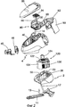
Фиг.2 - вид в разобранном состоянии основных деталей пылесоса.Figure 2 is an exploded view of the main parts of the vacuum cleaner.
Фиг.3 - вид в разобранном состоянии снизу и общий вид отдельных деталей пылесоса.Figure 3 is an exploded view from below and a general view of the individual parts of the vacuum cleaner.
Фиг.4 - вид в разобранном состоянии и общий вид обтекателя электродвигателя пылесоса.Figure 4 - view in disassembled condition and General view of the fairing of the electric motor of the vacuum cleaner.
Фиг.5 - вырыв опорной части пылесоса для второго способа реализации настоящего изобретения.Figure 5 - pulling out the supporting part of the vacuum cleaner for the second method of implementing the present invention.
Фиг.6 - общий вид сзади на пылесос.6 is a General rear view of the vacuum cleaner.
Фиг.7 - вид сверху на пылесос.7 is a top view of a vacuum cleaner.
Фиг.8 - поперечный разрез по A-A на фиг.7.Fig.8 is a cross section along A-A in Fig.7.
Фиг.9 и 10 представляют собой соответственно вид сбоку и сзади на отдельную деталь настоящего изобретения.Figures 9 and 10 are respectively a side and rear view of a separate part of the present invention.
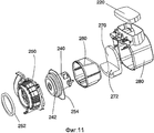
Фиг.11 - вид в разобранном состоянии узла пылесоса.11 is an exploded view of a vacuum cleaner assembly.
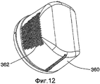
Фиг.12 и 13 показывают, на соответственно общем виде и виде в разрезе отдельных элементов пылесоса, варианты второго способа реализации настоящего изобретения.12 and 13 show, respectively, a General view and a sectional view of the individual elements of the vacuum cleaner, variants of the second method for implementing the present invention.
Как это показано на фиг. с 1 по 3, пылесос 1 согласно первому способу реализации настоящего изобретения состоит из корпуса, состоящего, в свою очередь, из трех основных деталей, изготовленных отдельно друг от друга, а потом собранных вместе:As shown in FIG. 1 to 3, the vacuum cleaner 1 according to the first implementation method of the present invention consists of a housing, which, in turn, consists of three main parts, made separately from each other, and then assembled together:
• малого нижнего корпуса 2, снабженного:• small
- гнездом 20 для размещения нижней части электродвигателя,-
- ячейкой 22 для размещения задних органов маневрирования пылесосом, таких как колеса или ролики (не показаны),- a
- выходным отверстием воздушного потока 26 пылесоса,- the outlet of the
- гнездом 30 нижней части устройства сматывания электрокабеля 10,-
• верхнего корпуса 4, включающего в себя:•
- пространство 40, предусмотренное для размещения мешка-фильтра для сбора пыли,- a
- гнездо 42 для размещения верхней части устройства сматывания электрокабеля 10,-
- пространство 48 для размещения передних органов маневрирования пылесосом (не показаны),-
- выемку 44 для размещения верхней части электродвигателя, совместно с гнездом 20 для размещения нижнего корпуса 2,- a
- вставку 45, позволяющую выполнить присоединение всасывающих патрубков, причем указанная вставка работает совместно с опорой мешка 46, расположенного в пространстве 40.- an
• задней детали 50, содержащей широкую ручку 52 для транспортировки пылесоса.• a
В соответствии с первым примером реализации настоящего изобретения, в качестве конструкционного материала пылесоса, по крайней мере, используемого для изготовления верхнего корпуса 4, а предпочтительно также и нижнего корпуса 2 и задней детали 50, применяется вспененный полипропилен (PPE).According to a first embodiment of the present invention, foamed polypropylene (PPE) is used as the structural material of a vacuum cleaner at least used to make the
В то же время для усиления сопротивления ударам ручки 52 задняя деталь 50 снабжается сердечником из невспененного полипропилена PP, придающего детали 50 механическую прочность на случай возможного нанесения по указанной ручке сильного удара.At the same time, to increase the resistance to impacts of the
Тем не менее, невысокая механическая прочность вспененного полипропилена (PPE) обусловливает необходимость значительного увеличения толщины стенок конструкции для придания ей необходимой жесткости. Оказывается однако (и это удивительно), что, если увеличение объема необходимого материала приводит к созданию более габаритной по своим размерам конструкции пылесоса по сравнению с его нормальным образцом, то масса необходимой для изготовления аппарата пластмассы может быть значительно уменьшена, а сам вес пылесоса в уже окончательно готовом виде может быть снижен вдвое.However, the low mechanical strength of foamed polypropylene (PPE) necessitates a significant increase in the wall thickness of the structure to give it the necessary rigidity. It turns out, however (and this is surprising), that if an increase in the volume of the required material leads to the creation of a vacuum cleaner with a larger overall dimension than its normal sample, then the mass of plastic necessary for the manufacture of the apparatus can be significantly reduced, and the weight of the vacuum cleaner is already finally finished form can be halved.
В то же время количество материала, необходимого для изготовления пылесоса, остается более низким по сравнению с пылесосом классической конструкции, что представляет собой с экономической точки зрения еще одно преимущество настоящего изобретения, так как благодаря этому обстоятельству снижается стоимость изготовления аппарата.At the same time, the amount of material required for the manufacture of the vacuum cleaner remains lower compared to a vacuum cleaner of a classical design, which is from an economic point of view another advantage of the present invention, since due to this circumstance the manufacturing cost of the apparatus is reduced.
Высокая пластичность вспененного полипропилена (PPE) обеспечивает ему более высокое звукопоглощение по сравнению с другими традиционно применяемыми для изготовления пылесосов пластмассами. Эта указанная высокая пластичность рассматриваемого материала сочетается у него, в зависимости от степени его расширения, с определенной присущей ему пластичной памятью, что представляет собой еще одно из значительных преимуществ применения этого материала, проявляющееся при окончательной сборке аппарата и установке на него различных комплектующих деталей. В самом деле, появляется таким образом возможность шарнирно соединять между собой, например, без шарниров различные крышки и достаточно просто фиксировать их в нужном положении за счет деформирования самого материала. Эта удивительная особенность рассматриваемого материала позволяет также без каких-либо усилий фиксировать в нем различные вставки простым вдавливанием в их тело материала.The high ductility of foamed polypropylene (PPE) provides it with higher sound absorption compared to other plastics traditionally used for the manufacture of vacuum cleaners. This indicated high ductility of the material under consideration is combined with it, depending on the degree of expansion, with a certain plastic memory inherent to it, which is another of the significant advantages of using this material, which manifests itself in the final assembly of the apparatus and the installation of various components on it. In fact, in this way it becomes possible to pivotally interconnect various covers, for example, without hinges, and simply fix them in the desired position by deforming the material itself. This amazing feature of the material under consideration also allows you to fix various inserts in it by simply pressing material into their body without any effort.
В самом деле, достаточно лишь «заставить» материал деформироваться, чтобы он заблокировал или зафиксировал вставку, и материал после деформации станет постоянно удерживать вложенную в него деталь.In fact, it is enough just to “force” the material to deform so that it blocks or fixes the insert, and after deformation the material will constantly hold the part embedded in it.
Таким образом, в предлагаемом примере крышка 80 изготовляется из вспененного полипропилена и располагается в верхнем корпусе. Механическая прочность крышки в верхнем корпусе 4 пылесоса обеспечивается за счет ее вдавливания в корпус и деформации рассматриваемого материала, как это было описано выше.Thus, in the proposed example, the
Указанная крышка позволяет обеспечить закрытие отделения, в котором располагается мешок для сбора пыли и позволяет направить воздушный поток, выходящий из мешка в направлении блока электродвигателя. В качестве дополнительных возможностей использования крышки из рассматриваемого материала может быть рассмотрен вариант размещения в ее толщине различных аксессуаров всасывания, таких как маленькая щетка, насадок для всасывания и т.д.The specified cover allows you to ensure the closure of the compartment in which the bag is located to collect dust and allows you to direct the air flow coming out of the bag in the direction of the motor block. As additional possibilities for using the cover of the material in question, the option of placing various suction accessories in its thickness, such as a small brush, suction nozzles, etc., can be considered.
В предлагаемом примере прочность закрепления верхнего корпуса на нижнем корпусе обеспечивается с помощью стержней 12, 13, опирающихся на опоры, расположенные под нижним корпусом 2. Стержни 12 конструктивно соединены с задней деталью 50, тогда как стержень 13 сочленен с элементом жесткости 90, расположенным на верхнем корпусе 4.In the proposed example, the strength of fastening the upper case to the lower case is ensured by
Опоры стержней 12 и 13 под нижним корпусом 2 сочленены, в предпочтительном варианте изобретения, с не представленными на чертеже роликами пылесоса. Что касается центрального ролика, то это последнее устройство работает совместно с платформой 11, которая позволяет повторно отцентрировать ролик относительно пылесоса.The supports of the
Сборка собственно верхнего корпуса на нижнем корпусе состоит в рассматриваемом примере в завинчивании стержней 12 и 13 в соответствующие трубки, выходящие из деталей 90 и 50, причем трубки и/или стержни проходят, что является преимуществом настоящего изобретения, через часть верхнего корпуса 4. На фиг.2 показана, в частности, указанная трубка 14, выходящая из детали 90, причем в указанную трубку входит стержень 13, пересекающий нижний корпус 2 через отверстие 24.The assembly of the upper case itself on the lower case consists in the example under consideration in screwing the
Указанное выше завинчивание стержней в трубки позволяет прижать посредством деталей 90 и 50 верхний корпус к нижнему корпусу, при этом относительно значительная деформация полипропилена PPE позволяет, как это было описано выше, обеспечить герметичность нижнего корпуса относительно верхнего, причем без применения какой-либо специальной прокладки.The aforementioned screwing of the rods into the tubes allows the upper case to be pressed by means of
Жесткая деталь 90 может иметь самые различные формы и структуру, начиная с детали, покрывающей практически всю ширину верхнего корпуса и показанной в рассматриваемом примере позади отделения, содержащего мешок для сбора пыли, и кончая деталью с более выраженным полукруглым вырезом. Может быть также рассмотрен вариант изготовления одновременно и нескольких независящих друг от друга деталей.The
Опорная площадь под нижним корпусом может быть выполнена в виде пластины с более или менее значительной поверхностью, например в виде жесткой детали 11. Можно, таким образом, расположить жесткую деталь под нижним корпусом, а более сконцентрированные точки опоры на верхнем корпусе.The supporting area under the lower case can be made in the form of a plate with a more or less significant surface, for example, in the form of a
Жесткая деталь 90, расположенная на верхнем корпусе, обеспечивает возможность использования ее для выполнения других функций. Так, на жесткой детали 90 можно расположить, например, гнезда для размещения кнопки управления пуск/останов 60, связанной с выключателем, а также кнопки 68 для запуска операции по намотке электрошнура на устройство сматывания 10.The
Жесткая деталь 90 снабжена также гнездом 92 для размещения блока 94, содержащего сложенный фильтр типа HEPA, позволяющего фильтровать воздушный поток, выходящий из мешка для сбора пыли, до его поступления в электродвигатель.The
Сигнальные лампочки, органы управления и маневрирования пылесосом 60, 68, а также жесткая деталь 90, трубки 12, 13, а также ролики предпочтительно изготовлять из невспененного полипропилена.The signal lights, controls and maneuvers of the
Электропитание электродвигателя пылесоса осуществляется от бытовой электророзетки посредством шнура электропитания, смонтированного на устройстве сматывания 10. Электрические провода выходят из неподвижной части устройства сматывания электрокабеля и подключаются к двум клеммам 72 электронной платы 70. Две другие клеммы 72 электронной платы 70 используются для подключения к кнопке пуск/останов. И, наконец, оставшиеся клеммы 72 используются для подключения электродвигателя к системе электропитания.The vacuum cleaner’s electric motor is powered by a household power outlet via a power cord mounted on the
В рассматриваемом примере реализации настоящего изобретения пылесос 1 снабжен устройствами защиты токоведущих частей аппарата, то есть электрических соединений различных элементов контура электропитания электродвигателя.In this example implementation of the present invention, the vacuum cleaner 1 is equipped with devices for protecting the live parts of the apparatus, that is, the electrical connections of various elements of the power circuit of the electric motor.
Таким образом, устройство сматывания электрокабеля 10 содержит корпус 100, закрывающий заднюю часть устройства смотки электрошнура. Указанный корпус закрывает узлы соединений электропроводов, расположенные на уровне устройства смотки электрошнура.Thus, the
Электродвигатель, не представленный на чертеже, размещается, в соответствии с настоящим изобретением, в корпусе 120, крышка которого 122 снабжена вытяжной трубой 124. Корпус 120 состоит, что является преимуществом настоящего изобретения, из жестких деталей, выполненных из невспененного полипропилена.An electric motor, not shown, is housed, in accordance with the present invention, in a
Крышка 122 имеет в то же время отверстия 126, служащие для ввода воздушного потока, а также уплотнительную прокладку 128, обеспечивающую герметичность обтекателя электродвигателя в процессе прижатия друг к другу нижнего и верхнего корпусов.The
Электронная панель 70 полностью размещается в вытяжной трубе 124. Таким образом, провода электропитания из устройства сматывания электрокабеля подключены к двум клеммам 72 электронной панели, обеспечивающим подключение указанных проводов к указанной панели.The
Корпус 120 содержит также обтекатель 130 практически цилиндрической формы, окружающий электродвигатель, на который крепится посредством соединения байонетного типа крышка 122. Указанный обтекатель обеспечивает совместно с вытяжной трубой 124 защиту клеммы 72, а также подвижных элементов электородвигателя. Он позволяет также ограничить шум, создаваемый электродвигателем.The
С этой целью обтекатель содержит, что является преимуществом настоящего изобретения, множество отверстий 132 для вывода воздушного потока, причем указанные отверстия цилиндрической формы имеют диаметр порядка 2,5 мм. В соответствии с предлагаемым примером, обтекатель содержит более 400 отверстий, обеспечивающих общую площадь выходного отверстия порядка 21 см2.To this end, the fairing comprises, which is an advantage of the present invention, a plurality of
В целях еще большего снижения создаваемого электродвигателем шума вспененный материал 134 располагается перед отверстиями 132, причем указанный вспененный материал опирается на одну из практически вертикальных сторон верхнего корпуса 4. Подобный вспененный материал позволяет поглощать шум от удара воздушного потока о вертикальную стенку верхнего корпуса перед тем, как этот воздушный поток достигнет выходного отверстия 26 нижнего корпуса 2.In order to further reduce the noise generated by the electric motor, the
Как это хорошо видно из фиг.4, круглая форма обтекателя и используемого вместе с ним вспененного материала позволяет ограничить шум от удара воздушного потока и обратить в жидкое состояние воздушный поток на выходе из обтекателя.As can be clearly seen from figure 4, the round shape of the fairing and the foam material used with it makes it possible to limit the noise from the impact of the air stream and turn the air stream at the exit of the fairing into a liquid state.
Указанное выходное отверстие расположено, что является преимуществом настоящего изобретения, напротив отверстий 132, чтобы позволить удлинить траекторию движения воздушного потока и тем самым, безусловно, снизить шум от электродвигателя пылесоса. Отличительная особенность настоящего изобретения, обеспечивающая снижение шума, заключается в том, что вспененный материал 136 располагается внутри опоры 138, непосредственно перед отверстием выхода воздушного потока 26, как это представлено на фиг.4.The specified outlet is located, which is an advantage of the present invention, opposite the
Преимуществом настоящего изобретения является то, что обтекатели и блоки защиты выполнены из невспененного полипропилена с целью ограничения количества видов используемых звукопоглащающих материалов. Возможно, тем не менее, рассмотрение, в рамках настоящего изобретения, возможности использования и любого другого звукопоглащающего материала, обладающего необходимой электрической изоляцией и высокой механической прочностью, в частности стойкостью к проникновению в него остроконечного предмета.An advantage of the present invention is that fairings and protection units are made of non-foamed polypropylene in order to limit the number of types of sound-absorbing materials used. It is possible, however, to consider, within the framework of the present invention, the possibility of using any other sound-absorbing material having the necessary electrical insulation and high mechanical strength, in particular resistance to penetration into it of a pointed object.
Что касается вспененного полипропилена, то в настоящем изобретении этот материал должен использоваться при степенях вспенивания, величина которых будет определяться количеством материала (полипропилена) на литр. В настоящем изобретении предлагается предпочтительно использовать концентрации в диапазоне от 40 г до 80 г материала на литр.As for foamed polypropylene, in the present invention, this material should be used for foaming degrees, the value of which will be determined by the amount of material (polypropylene) per liter. The present invention proposes it is preferable to use concentrations in the range from 40 g to 80 g of material per liter.
В то же время с целью облегчения возможности последующей утилизации использованного полипропилена приоритет следует отдавать использованию гомополимеров.At the same time, in order to facilitate the possibility of subsequent disposal of used polypropylene, priority should be given to the use of homopolymers.
В соответствии со вторым способом реализации настоящего изобретения, пылесос 200 содержит, как это представлено на фиг. с 5 по 11, опорную часть, состоящую главным образом из верхнего корпуса 202 и нижнего корпуса. В целях наилучшего представления преимуществ настоящего изобретения нижний корпус конструкции на чертежах не представлен.According to a second embodiment of the present invention, the
На верхнем корпусе 202 установлен вариатор изменения мощности 210, а также две кнопки 212 и 214, позволяющие соответственно выполнять перемотку шнура электропитания электродвигателя, а также включать и выключать электродвигатель пылесоса.On the
Закругленному элементу передней части верхнего корпуса придана форма ручки 218. На верхней стороне корпуса 202 шарнирно закреплена крышка 215 с устройством подключения 216 всасывающего патрубка, не представленного на чертеже.The rounded element of the front of the upper housing is shaped like a
Верхний корпус содержит, в то же время, отделение 206, предназначенное для размещения мешка фильтрации воздушного потока и сбора засасываемого пылесосом мусора, причем указанное отделение закрыто в своей верхней части крышкой 215. Отделение 206 содержит на своей задней стороне 207 отверстия аэравлического соединения с отделением, в котором располагается электродвигатель.The upper case, at the same time, comprises a
На верхнем корпусе 202 установлен также передний ролик 230, а также задние ролики (не представленные на чертеже), и проходная втулка 222, предназначенная для направления шнура электропитания в сторону устройства смотки электрошнура.The
В соответствии с настоящим изобретением, электродвигатель 240 располагается в обтекателе, состоящем из двух частей: высокой части 250, закрывающей входное отверстие воздушного потока в электродвигатель, и низкой части 260, закрывающей выходное отверстие воздушного потока электродвигателя, как это показано на фиг.8. Обтекатель, следовательно, полностью окружает электродвигатель и позволяет таким образом снизить шум от работающего пылесоса за счет помещения электродвигателя последнего в созданное указанным образом замкнутое пространство.In accordance with the present invention, the
На фиг.11 показана компоновка размещения электродвигателя в обтекателе. Прокладка 242 обеспечивает герметизацию отверстия ввода воздуха от электродвигателя внутрь обтекателя, тогда как прокладка 252 обеспечивает герметизацию аэравлического соединения отделения 206, предназначенного для размещения мешка для всасываемого пылесосом мусора и зоны электродвигателя.Figure 11 shows the layout of the placement of the electric motor in the fairing. The
Кроме того, прокладка 254 обеспечивает герметизацию зазора между двух частей обтекателя.In addition, the
В то же время низкая часть 260 обтекателя содержит множество отверстий 262, обеспечивающих вывод воздушного потока из обтекателя. Напротив указанных отверстий располагается абсорбирующий элемент 270 из вспененного материала. Указанный вспененный материал располагается практически вдоль всей траектории движения воздуха, начиная с выходного отверстия обтекателя и кончая выходным отверстием опорной части пылесоса, причем указанное выходное отверстие проходит через фильтр 220 типа HEPA.At the same time, the
Преимуществом настоящего изобретения является то, что, как это показано на фиг.8 и 11, нижний обтекатель 260 электородвигателя, а также вспененный материал 270 и фильтр HEPA 220 располагаются в опоре 280, закрепленной на верхнем обтекателе 250, причем указанная опора представляет собой таким образом второй обтекатель, который за счет своей показанной на чертеже стенки позволяет еще значительней снизить шум снаружи аппарата.An advantage of the present invention is that, as shown in FIGS. 8 and 11, the
Размер и количество отверстий 262 практически те же самые, что были указаны выше. Указанные отверстия располагаются, что является преимуществом рассматриваемого изобретения, в точках пересечения вертикальных и горизонтальных линий условной сетки, как это показано на фиг.10, причем горизонтальный шаг “p” составляет порядка 6 мм, а вертикальный шаг “q “ - около 3,5 мм. Может также быть рассмотрена и возможность использования шага переменного значения, величина которого будет зависеть от относительного расположения отверстий относительно отверстия выхода воздуха из опорной части пылесоса.The size and number of
В то же время толщина “e” обтекателя 260 на уровне отверстий составляет величину порядка 4 мм, причем указанная толщина позволяет обеспечить формирование ламинарного воздушного потока на выходе из обтекателя. Кроме того, указанная толщина достаточна, согласно одному из усовершенствований настоящего изобретения, для образования в ней отверстий, имеющих форму усеченного конуса, то есть таких отверстий, сечение которых расширяется в направлении от внутренней части обтекателя к его внешней части, причем указанные отверстия благодаря тому, что они имеют форму сопла, позволяют снизить выходные скорости воздушного потока.At the same time, the thickness “ e” of the fairing 260 at the level of the holes is about 4 mm, and this thickness allows the formation of a laminar air flow at the exit of the fairing. In addition, this thickness is sufficient, according to one of the improvements of the present invention, for the formation in it of holes having the shape of a truncated cone, that is, such holes whose cross section expands in the direction from the inner part of the fairing to its outer part, and these holes due to because they are nozzle-shaped, they can reduce the output air velocity.
Согласно отличительной особенности настоящего изобретения, указанные отверстия располагаются на задней и нижней сторонах обтекателя, то есть в месте, расположенном напротив отверстия выхода воздушного потока из опорной части аппарата, причем указанное выходное отверстие проходит через фильтр 220.According to a distinguishing feature of the present invention, these openings are located on the rear and lower sides of the fairing, that is, in a place opposite the air outlet opening from the supporting part of the apparatus, said outlet opening passing through a
При работе пылесоса воздушный поток, пройдя через фильтровальный мешок, а затем электродвигатель, покидает этот последний, в соответствии со стрелкой, изображенной на фиг.8. Затем через отверстия 262 он покидает обтекатель перед тем, как пройти вдоль абсорбирующего элемента 270, чтобы затем уже окончательно покинуть опорную часть, пройдя через фильтр 220.During the operation of the vacuum cleaner, the air flow, passing through the filter bag, and then the electric motor, leaves this last one, in accordance with the arrow depicted in Fig. 8. Then, through the
Как это хорошо видно из фиг.8 и 9, наименьшая величина проходного сечения канала, обеспечивающего прохождение воздуха на уровне высоты “a “ стенок обтекателя 260, предусмотрена в случае отверстий, удаленных от отверстия выхода воздушного потока из опорной части аппарата, что сделано для компенсации небольшой величины скорости воздуха на выходе из этих отверстий.As can be clearly seen from Figs. 8 and 9, the smallest passage section of the channel that allows air to pass at a height level “ a ” of the walls of the fairing 260 is provided in the case of openings remote from the air outlet outlet from the support part of the apparatus, which was done to compensate small air velocity at the outlet of these holes.
Величина пропускного сечения S1 канала, обеспечивающего прохождение воздуха, меньше, таким образом, величины пропускного сечения S2 канала, обеспечивающего прохождение воздуха, что позволяет распределить воздушный поток практически по всей ширине просверленной зоны поверхности обтекателя.The value of the flow cross section S 1 of the channel providing the passage of air is thus less than the value of the flow cross section S2 of the channel providing the passage of air, which makes it possible to distribute the air flow over almost the entire width of the drilled zone of the fairing surface.
Указанное изменение сечения обеспечивается за счет придания вспененному материалу 270 изогнутой поверхности 272, что позволяет обеспечить постепенное и линейное изменение размера сечения, позволяющее, в свою очередь, ограничить турбулентность воздушного потока и ослабить шум от его ударов о поверхность канала истечения.The specified change in the cross section is provided by giving the foam 270 a
Такое более гомогенное распределение воздушного потока на выходе из указанного обтекателя способствует таким образом снижению аэравлического шума.Such a more homogeneous distribution of the air flow at the outlet of the said cowl thus contributes to a reduction in air noise.
На фиг.12 и 13 представлен вариант изготовления обтекателя электродвигателя, соответствующий этому второму способу реализации настоящего изобретения.12 and 13 show an embodiment of a motor fairing according to this second embodiment of the present invention.
Итак, на фиг.12 представлена низкая часть 360 обтекателя электродвигателя, причем эта низкая часть снабжена отверстиями 362, размер, количество и плотность которых практически те же самые, что и в случае, описанном выше. Следует, однако, заметить, что отверстия 362 располагаются в рассматриваемом случае исключительно на нижней стенке низкой части обтекателя, напротив отверстия выхода воздушного потока 320 из опорной части пылесоса, как это показано на фиг.13, представляющей вид в разрезе электродвигателя и работающих с ним совместно обтекателей.So, in Fig.12 presents the
Электродвигатель 340 располагается таким образом в обтекателе, состоящем из высокой части 350 и из низкой части 360. Отверстия 362, предназначенные для выхода воздушного потока из обтекателя, позволяют направить воздушный поток вниз. Звукопоглощающий материал 370 в том виде, в котором он был описан выше, располагается напротив отверстий, снаружи обтекателя, с тем, чтобы поглощать часть акустической энергии, выделяемой выходящим потоком воздуха. Указанным звукопоглощающим материалом оснащен второй обтекатель 380, закрепленный на верхней части первого обтекателя.The
Как это хорошо видно на фиг.13, пропускное сечение воздушного потока на выходе из низкой части 360 обтекателя увеличивается в направлении движения воздушного потока с целью распределения воздушного потока по указанным отверстиям и ограничения разброса скоростей на этом уровне.As can be clearly seen in FIG. 13, the air flow cross section at the exit from the low portion of the fairing 360 increases in the direction of the air flow movement in order to distribute the air flow over these openings and limit the velocity spread at this level.
Настоящее изобретение не ограничивается двумя примерами его реализации и приведенными усовершенствованиями, но, напротив, охватывает все возможные технические варианты рассмотренных решений.The present invention is not limited to two examples of its implementation and the above improvements, but, on the contrary, covers all possible technical options for the considered solutions.
Claims (10)
Applications Claiming Priority (2)
| Application Number | Priority Date | Filing Date | Title |
|---|---|---|---|
| FR0605770A FR2902632B1 (en) | 2006-06-27 | 2006-06-27 | VACUUM |
| FR0605770 | 2006-06-27 |
Publications (2)
| Publication Number | Publication Date |
|---|---|
| RU2009102543A RU2009102543A (en) | 2010-08-10 |
| RU2416356C2 true RU2416356C2 (en) | 2011-04-20 |
Family
ID=37398652
Family Applications (1)
| Application Number | Title | Priority Date | Filing Date |
|---|---|---|---|
| RU2009102543/12A RU2416356C2 (en) | 2006-06-27 | 2007-06-26 | Vacuum cleaner |
Country Status (7)
| Country | Link |
|---|---|
| EP (1) | EP2032010B1 (en) |
| KR (1) | KR20090035551A (en) |
| CN (1) | CN101478909B (en) |
| ES (1) | ES2549114T3 (en) |
| FR (1) | FR2902632B1 (en) |
| RU (1) | RU2416356C2 (en) |
| WO (1) | WO2008000947A1 (en) |
Families Citing this family (4)
| Publication number | Priority date | Publication date | Assignee | Title |
|---|---|---|---|---|
| FR2950240B1 (en) * | 2009-09-18 | 2012-09-21 | Seb Sa | VACUUM |
| CN102648834A (en) * | 2011-02-24 | 2012-08-29 | 苏州韩京姬科技有限公司 | Sweeper |
| US8578553B2 (en) * | 2011-03-04 | 2013-11-12 | G.B.D. Corp. | Sound shield for a surface cleaning apparatus |
| FR2979814B1 (en) * | 2011-09-12 | 2013-08-23 | Seb Sa | VACUUM COMPRISING A SILENCER AND AN AIR DIFFUSER |
Family Cites Families (7)
| Publication number | Priority date | Publication date | Assignee | Title |
|---|---|---|---|---|
| DE3402603A1 (en) * | 1984-01-26 | 1985-08-01 | Electrostar Schöttle GmbH & Co, 7313 Reichenbach | Vacuum cleaner |
| DE3443837A1 (en) * | 1984-11-30 | 1986-06-05 | Progress-Elektrogeräte Mauz & Pfeiffer GmbH & Co, 7000 Stuttgart | VACUUM CLEANER |
| DE4100858A1 (en) * | 1991-01-14 | 1992-07-16 | Siemens Ag | Vacuum cleaner with blower unit - has blower in inner housing capsule located in outer capsule, leaving flow space, and free space between outer capsule and housing |
| DK0896759T3 (en) * | 1996-04-30 | 2002-02-25 | Vorwerk Co Interholding | Fast-moving electric motor |
| DE10161875A1 (en) * | 2001-12-09 | 2003-09-04 | Kern Gmbh Dr | Vacuum cleaner housing accommodates working elements which either singly or as combined units are installed into appropriately shaped seatings in the housing sections consisting of a foam material |
| FR2873563B1 (en) * | 2004-07-29 | 2006-09-22 | Seb Sa | VACUUM |
| KR101143773B1 (en) * | 2004-12-03 | 2012-05-11 | 엘지전자 주식회사 | Noise reduction system for fan-motor of vacuum cleaner |
-
2006
- 2006-06-27 FR FR0605770A patent/FR2902632B1/en not_active Expired - Fee Related
-
2007
- 2007-06-26 WO PCT/FR2007/001062 patent/WO2008000947A1/en active Application Filing
- 2007-06-26 CN CN2007800242988A patent/CN101478909B/en not_active Expired - Fee Related
- 2007-06-26 ES ES07803775.1T patent/ES2549114T3/en active Active
- 2007-06-26 RU RU2009102543/12A patent/RU2416356C2/en not_active IP Right Cessation
- 2007-06-26 KR KR1020097001741A patent/KR20090035551A/en not_active Application Discontinuation
- 2007-06-26 EP EP07803775.1A patent/EP2032010B1/en active Active
Also Published As
| Publication number | Publication date |
|---|---|
| ES2549114T3 (en) | 2015-10-23 |
| FR2902632A1 (en) | 2007-12-28 |
| EP2032010A1 (en) | 2009-03-11 |
| RU2009102543A (en) | 2010-08-10 |
| KR20090035551A (en) | 2009-04-09 |
| WO2008000947A1 (en) | 2008-01-03 |
| CN101478909B (en) | 2011-07-27 |
| FR2902632B1 (en) | 2012-06-08 |
| CN101478909A (en) | 2009-07-08 |
| EP2032010B1 (en) | 2015-07-08 |
Similar Documents
| Publication | Publication Date | Title |
|---|---|---|
| US8940082B2 (en) | Filter element for an extractor hood and extractor hood | |
| US8155508B2 (en) | Drying apparatus | |
| KR101921274B1 (en) | Side emitting nondirectional air purifier | |
| CN1811293A (en) | Humidifier | |
| RU2416356C2 (en) | Vacuum cleaner | |
| US7690077B2 (en) | Central vacuum units with an acoustic damping pathway | |
| JPH0328088A (en) | Wheel housing shell which works cooperatively together with mud-guard of automobile | |
| CN102025215A (en) | Motor cover for dust collector | |
| CN101422335B (en) | Hand dryer | |
| US7470298B2 (en) | Device for effectively removing suspended particles from an airflow | |
| KR20130107535A (en) | Humidifier | |
| CN100478050C (en) | Spray type dust separator | |
| JP4020138B2 (en) | Hand dryer | |
| US20020066155A1 (en) | Vacuum cleaner | |
| JP3627175B2 (en) | Airflow control type smoke separator | |
| WO2021212564A1 (en) | Air purifying apparatus, air conditioner indoor unit, air conditioner, and fresh air system | |
| KR20120113028A (en) | Humidification apparatus | |
| CN205064314U (en) | Domestic air pump | |
| JP3931308B2 (en) | Smoking space construction machine | |
| JP4678626B2 (en) | Laminar air flow control type air purifier | |
| CN212105391U (en) | Dustproof device and dustproof system | |
| CN220832887U (en) | Hair collecting device | |
| JP3627165B2 (en) | Smoking space creation system | |
| CN212566100U (en) | Top-water-adding ultrasonic atomization humidifier | |
| JP3627172B2 (en) | Airflow control type smoke separator |
Legal Events
| Date | Code | Title | Description |
|---|---|---|---|
| MM4A | The patent is invalid due to non-payment of fees |
Effective date: 20160627 |