RU2414373C1 - Transport facility cabin suspension (versions) - Google Patents
Transport facility cabin suspension (versions) Download PDFInfo
- Publication number
- RU2414373C1 RU2414373C1 RU2010102749/11A RU2010102749A RU2414373C1 RU 2414373 C1 RU2414373 C1 RU 2414373C1 RU 2010102749/11 A RU2010102749/11 A RU 2010102749/11A RU 2010102749 A RU2010102749 A RU 2010102749A RU 2414373 C1 RU2414373 C1 RU 2414373C1
- Authority
- RU
- Russia
- Prior art keywords
- levers
- pivoted
- cab
- supports
- cabin
- Prior art date
Links
Images

Landscapes
- Vehicle Body Suspensions (AREA)
- Body Structure For Vehicles (AREA)
Abstract
Description
Изобретение относится к области машиностроения и может быть использовано в подвесках кабин.The invention relates to mechanical engineering and can be used in cab suspensions.
Известна подвеска кабины грузового автомобиля, выбранная в качестве ближайшего аналога, содержащая передние шарнирные опоры с рычагами и задние опоры, выполненные в виде пружины и амортизатора, при этом передние опоры жестко связаны балкой, на которой установлен рычаг для обеспечения продольной устойчивости, второй конец которого закреплен на раме автомобиля, и П-образный рычаг, закрепленный при помощи кронштейна на раме автомобиля с возможностью поворота для обеспечения поперечной устойчивости, при этом на указанной балке также закреплен кронштейн с отверстиями для фиксации передних опор при опрокидывании кабины (патент РФ на изобретение №2306238, МПК B62D 33/077, B60G 21/00, B60G 11/46, опубл. 20.09.07).Known suspension of a truck cabin, selected as the closest analogue, containing front articulated bearings with levers and rear supports made in the form of a spring and a shock absorber, while the front supports are rigidly connected by a beam on which a lever is mounted to provide longitudinal stability, the second end of which is fixed on the frame of the car, and a U-shaped lever fixed with a bracket on the frame of the car with the possibility of rotation to ensure lateral stability, while on the specified beam is also closed captive bracket with holes for fixing the front supports when tipping the cab (RF patent for the invention No. 2306238, IPC B62D 33/077, B60G 21/00,
Данная подвеска не обеспечивает высоких эксплутационных характеристик грузового автомобиля.This suspension does not provide high operational characteristics of the truck.
Была поставлена задача за счет снижения вертикальных колебаний улучшить условия эксплуатации грузового автомобиля.The task was set to improve the operating conditions of a truck by reducing vertical vibrations.
Указанная задача решается тем, что в известной подвеске кабины транспортного средства, содержащей передние шарнирные опоры с рычагами и задние опоры, выполненные в виде пружины с амортизатором, одним концом закрепленные на раме, а другим шарнирно - на кабине, передние опоры дополнительно содержат тяги, шарнирно связанные с мостом и с рычагами, при этом рычаги выполнены двуплечими и шарнирно прикреплены свободным концом через кронштейн к кабине, а средней частью через опорный элемент - к раме, кроме того, задние опоры закреплены на раме шарнирно.This problem is solved in that in the known suspension of the vehicle cabin containing front articulated supports with levers and rear supports, made in the form of a spring with a shock absorber, one end mounted on the frame, and the other articulated on the cab, the front supports additionally contain rods, articulated connected with the bridge and with levers, while the levers are made of two shoulders and pivotally attached by the free end through the bracket to the cab, and the middle part through the support element to the frame, in addition, the rear supports are mounted on the frame of the hinge irno.
По варианту два в подвеске кабины транспортного средства, содержащей шарнирно закрепленные на кабине передние опоры с рычагами и задние опоры, задние опоры также снабжены рычагами, при этом передние и задние опоры дополнительно содержат тяги, шарнирно связанные с мостом и с рычагами, при этом рычаги выполнены двуплечими и шарнирно прикреплены свободным концом через кронштейн к кабине, а средней частью через опорный элемент - к раме.Alternatively, two in the suspension of the vehicle cabin, comprising front supports with levers and rear supports pivotally mounted on the cabin, rear supports are also equipped with levers, while the front and rear supports additionally contain rods pivotally connected to the bridge and with levers, while the levers are made two shoulders and pivotally attached with their free end through the bracket to the cab, and the middle part through the support element to the frame.
По варианту три в подвеске кабины транспортного средства, содержащей шарнирно закрепленные на кабине опоры с рычагами, опоры дополнительно содержат тяги, шарнирно связанные с кабиной и с установленными на корпусе главной передачи рычагами, при этом рычаги выполнены двуплечими и шарнирно прикреплены свободным концом к поворотному кулаку колеса.According to option three, in the suspension of the vehicle cabin containing the supports with levers pivotally mounted on the cab, the supports additionally comprise rods pivotally connected to the cab and with levers mounted on the main gear housing, the levers being made with two shoulders and pivotally attached with the free end to the steering knuckle of the wheel .
По варианту четыре в подвеске кабины транспортного средства, содержащей шарнирно закрепленные на кабине опоры с рычагами, опоры дополнительно снабжены тягами, шарнирно связывающими выполненные двуплечими верхний и нижний рычаги, при этом тяги связаны с одним из плеч верхних рычагов, закрепленных своей средней частью с помощью опорного элемента на раме автомобиля с возможностью поворота, а свободным плечом шарнирно связанных с кабиной, и средней частью нижних рычагов, шарнирно закрепленных одним плечом на корпусе главной передачи, а другим плечом шарнирно прикрепленных к поворотному кулаку колеса.According to option four, in the suspension of the vehicle cabin containing the supports with levers pivotally mounted on the cab, the supports are additionally provided with rods pivotally connecting the upper and lower levers made with two shoulders, the rods being connected to one of the arms of the upper levers secured with their middle part using the support element on the car frame with the possibility of rotation, and the free shoulder pivotally connected to the cab, and the middle part of the lower levers pivotally mounted with one shoulder on the main gear housing, and with a shoulder pivotally attached to the steering knuckle of the wheel.
Наличие в подвесках тяг, шарнирно связанных с выполненными двуплечими рычагами, позволяет свести до минимума влияние вертикальных перемещений моста на кабину. Положительным является и то, что данные конструктивные исполнения подвесок позволяют компенсировать неровности дороги с отслеживающим эффектом, а именно как двигается мост, так и перемещается кабина, но только в противофазе, уменьшая вертикальные нагрузки в кабине. Это позволяет очень быстро, в такт, отслеживать перемещение моста без инерционного запаздывания.The presence in the suspension rods pivotally connected to the made two-arm levers, allows to minimize the effect of vertical movements of the bridge on the cab. It is also positive that these suspension designs allow you to compensate for bumps in the road with a tracking effect, namely, how the bridge moves and the cab moves, but only in antiphase, reducing vertical loads in the cab. This allows you to very quickly, in time, track the movement of the bridge without inertial delay.
На основании вышеизложенного можно сделать вывод, что заявляемое техническое решение соответствует критерию «новизна».Based on the foregoing, we can conclude that the claimed technical solution meets the criterion of "novelty."
Анализ известных технических решений в данной области техники показал, что предложенная подвеска кабины транспортного средства имеет признаки, которые отсутствуют в аналогах, а их использование в заявляемой совокупности существенных признаков позволяет получить новый технический результат. Следовательно, заявляемое техническое решение соответствует условию «изобретательский уровень».An analysis of the known technical solutions in this technical field showed that the proposed suspension of the vehicle cabin has features that are not in the analogues, and their use in the claimed combination of essential features allows to obtain a new technical result. Therefore, the claimed technical solution meets the condition of "inventive step".
Предлагаемая подвеска кабины транспортного средства поясняется схематичными изображениями:The proposed suspension of the vehicle cabin is illustrated in schematic images:
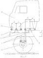
фиг.1 - вариант 1 исполнения;figure 1 -
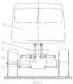
фиг.2 - вариант 2 исполнения;figure 2 -
фиг.3 - вариант 3 исполнения;figure 3 - option 3 execution;
фиг.4 - вариант 4 исполнения.figure 4 -
Подвеска кабины транспортного средства по вариантам один и два (фиг.1-2) содержит передние шарнирные опоры и задние опоры, устанавливаемые попарно слева и справа.The suspension of the vehicle cabin according to the options one and two (Fig.1-2) contains front articulated supports and rear supports mounted in pairs on the left and right.
Передняя опора содержит тяги 1, шарнирно связанные с двуплечими рычагами 2.The front support contains
В подвеске по варианту один задние опоры выполнены в виде пружины 3 с амортизатором 4 и шарнирно одним концом закреплены на раме 5, а другим концом - на кабине 6.In the suspension, according to the variant, one of the rear supports is made in the form of a spring 3 with a
Каждая из тяг 1 передних опор одним концом шарнирно связана с мостом 7, а другим - с двуплечим рычагом 2, который свободным концом через кронштейн 8 шарнирно закреплен на кабине, а средней частью с помощью опорного элемента 9 закреплен с возможностью поворота на раме 5 автомобиля.Each of the
В подвеске кабины транспортного средства по варианту два передние и задние опоры выполнены шарнирными и содержат тяги 1, шарнирно связанные с двуплечими рычагами 2.In the suspension of the vehicle cabin, according to an embodiment, the two front and rear supports are hinged and comprise
Каждая из тяг 1 опор одним концом шарнирно связана с мостом 10, а другим - с двуплечим рычагом 2, который свободным концом через кронштейн 11 шарнирно закреплен на кабине, а средней частью с помощью опорного элемента 12 закреплен с возможностью поворота на раме 5 автомобиля.Each of the
В подвеске кабины транспортного средства с независимой подвеской колес по вариантам три и четыре (фиг.3, 4) по две опоры устанавливают в центральной части кабины.In the suspension of a vehicle cabin with independent wheel suspension, three and four variants (Figs. 3, 4) of two supports are installed in the central part of the cabin.
В третьем варианте исполнения тяги 1 шарнирно связаны с кабиной 6 и с двуплечими рычагами 2. Рычаги 2 установлены на корпусе 13 главной передачи с возможностью поворота, а свободным концом шарнирно прикреплены к поворотному кулаку 14 колеса.In the third embodiment, the
В подвеске кабины транспортного средства по четвертому варианту исполнения тяга 1 каждой из опор шарнирно связывает одно плечо двуплечего верхнего рычага 2 и среднюю часть двуплечего нижнего рычага 15. Верхний рычаг 2 опоры закреплен своей средней частью с помощью опорного элемента 16 на раме автомобиля с возможностью поворота, а свободным плечом шарнирно связан с кабиной 6. Нижний рычаг шарнирно закреплен одним плечом на корпусе 13 главной передачи, а другим плечом шарнирно прикреплен к поворотному кулаку 14 колеса.In the suspension of the vehicle cabin according to the fourth embodiment, the
Подвеска кабины по первому варианту исполнения работает в паре с мостом автомобиля: при его перемещении по неровной дороге возникают разнонаправленные движения кабины и моста, при этом двуплечий рычаг 2, закрепленный на опорном элементе 9, как раз и позволяет выполнить перемещение в противофазе к перемещению моста. Так, при наезде колес с мостом на неровность (бугор, камень и т.д.) мост идет вверх. Во всех других известных случаях это движение через подвеску автомобиля передается на кабину почти полностью (если подвеска кабины жесткая) или частично (если подвеска кабины упругая гасящая). В нашем случае тяга 1, идущая вверх, опирается верхним концом в правую сторону двуплечего рычага 2, поворачивая его через центр против часовой стрелки. Левая сторона двуплечего рычага 2, закрепленная шарнирно на кронштейне 8 кабины, идет вниз и тянет за собой всю кабину. Это движение осуществляется с частотой и амплитудой хода моста и колес, только в другом направлении. При равных плечах этого рычага (А=В) происходит почти полное погашение этого перемещения моста вверх. При перемещении моста вниз подвеска работает аналогично. Дополнительный положительный эффект выражается в том, что для водителя и пассажира увеличивается комфорт, снижается усталость, одновременно увеличивается средняя скорость движения автомобиля. За счет изменения отношения длины А к В можно изменить величину (амплитуду) перемещения кабины относительно моста. Данная схема проста и надежна, не требует применения сложных и дорогих следящих электронных систем, для которых необходима дополнительная мощность от двигателя, а по сравнению с гидравлическими подвесками - менее громоздка, более дешева и надежна.The cab suspension according to the first embodiment works in tandem with the car’s bridge: when it moves along rough roads, there are multidirectional movements of the cab and the bridge, while the two-
Для быстрых автомобилей, в том числе и спортивных, водителю, чтобы лучше оценить ситуацию, нужна информативность от поверхности дороги. Это обеспечивает только жесткое крепление кабины к раме. Недостатком такого крепления является ограничение дальнейшего повышения скорости автомобиля из-за увеличения динамических нагрузок. Всех этих недостатков лишена подвеска по варианту два - полностью жесткая подвеска без упругих элементов, обладающая таким качеством, как информативность, позволяющая водителю быстро отслеживать состояние дороги, адекватно оценивать и быстро реагировать, изменяя скорость и траекторию движения автомобиля. Это достигается наличием двуплечих рычагов 2 и тяг 1 в передних и задних опорах подвески кабины.For fast cars, including sports cars, the driver, in order to better assess the situation, needs information from the road surface. This provides only rigid attachment of the cab to the frame. The disadvantage of this mount is the limitation of a further increase in vehicle speed due to an increase in dynamic loads. Suspension is deprived of all these shortcomings according to option two - a completely stiff suspension without elastic elements, which has such a quality as information content that allows the driver to quickly monitor the condition of the road, adequately evaluate and respond quickly, changing the speed and trajectory of the car. This is achieved by the presence of two shoulders levers 2 and
Варианты исполнения подвески три и четыре устанавливаются на транспортные средства с независимой подвеской колес.Three and four suspension options are installed on vehicles with independent wheel suspension.
Данная конструкция подвески кабины транспортного средства обладает высокими эксплуатационными характеристиками, проста в исполнении.This design of the suspension of the vehicle cabin has high performance, simple to perform.
Предложенная подвеска соответствует условию промышленной применимости и может быть изготовлена на стандартном оборудовании с применением освоенных ранее технологий и материалов.The proposed suspension meets the conditions of industrial applicability and can be manufactured on standard equipment using previously developed technologies and materials.
Claims (4)
Priority Applications (1)
| Application Number | Priority Date | Filing Date | Title |
|---|---|---|---|
| RU2010102749/11A RU2414373C1 (en) | 2010-01-27 | 2010-01-27 | Transport facility cabin suspension (versions) |
Applications Claiming Priority (1)
| Application Number | Priority Date | Filing Date | Title |
|---|---|---|---|
| RU2010102749/11A RU2414373C1 (en) | 2010-01-27 | 2010-01-27 | Transport facility cabin suspension (versions) |
Publications (1)
| Publication Number | Publication Date |
|---|---|
| RU2414373C1 true RU2414373C1 (en) | 2011-03-20 |
Family
ID=44053641
Family Applications (1)
| Application Number | Title | Priority Date | Filing Date |
|---|---|---|---|
| RU2010102749/11A RU2414373C1 (en) | 2010-01-27 | 2010-01-27 | Transport facility cabin suspension (versions) |
Country Status (1)
| Country | Link |
|---|---|
| RU (1) | RU2414373C1 (en) |
Cited By (2)
| Publication number | Priority date | Publication date | Assignee | Title |
|---|---|---|---|---|
| CN110843637A (en) * | 2019-12-21 | 2020-02-28 | 广州百靓科技有限公司 | Cargo vehicle capable of lifting to flat ground |
| RU219944U1 (en) * | 2023-06-07 | 2023-08-15 | Публичное акционерное общество "КАМАЗ" | Truck cab suspension |
Citations (4)
| Publication number | Priority date | Publication date | Assignee | Title |
|---|---|---|---|---|
| FR2432966A1 (en) * | 1978-08-11 | 1980-03-07 | Fiat Ricerche | ELASTIC SUSPENSION FOR AN AGRICULTURAL TRACTOR CAB |
| SU1123925A1 (en) * | 1983-07-29 | 1984-11-15 | Сибирский Ордена Трудового Красного Знамени Автомобильно-Дорожный Институт Им.В.В.Куйбышева | Suspension for vehicle cabin |
| SU1643293A1 (en) * | 1988-09-15 | 1991-04-23 | Минский автомобильный завод | Mounting of transport vehicle cab |
| RU2306238C1 (en) * | 2006-01-17 | 2007-09-20 | Николай Александрович Рогушин | Truck cab suspension |
-
2010
- 2010-01-27 RU RU2010102749/11A patent/RU2414373C1/en not_active IP Right Cessation
Patent Citations (4)
| Publication number | Priority date | Publication date | Assignee | Title |
|---|---|---|---|---|
| FR2432966A1 (en) * | 1978-08-11 | 1980-03-07 | Fiat Ricerche | ELASTIC SUSPENSION FOR AN AGRICULTURAL TRACTOR CAB |
| SU1123925A1 (en) * | 1983-07-29 | 1984-11-15 | Сибирский Ордена Трудового Красного Знамени Автомобильно-Дорожный Институт Им.В.В.Куйбышева | Suspension for vehicle cabin |
| SU1643293A1 (en) * | 1988-09-15 | 1991-04-23 | Минский автомобильный завод | Mounting of transport vehicle cab |
| RU2306238C1 (en) * | 2006-01-17 | 2007-09-20 | Николай Александрович Рогушин | Truck cab suspension |
Cited By (3)
| Publication number | Priority date | Publication date | Assignee | Title |
|---|---|---|---|---|
| CN110843637A (en) * | 2019-12-21 | 2020-02-28 | 广州百靓科技有限公司 | Cargo vehicle capable of lifting to flat ground |
| RU219944U1 (en) * | 2023-06-07 | 2023-08-15 | Публичное акционерное общество "КАМАЗ" | Truck cab suspension |
| RU222306U1 (en) * | 2023-10-11 | 2023-12-19 | Общество С Ограниченной Ответственностью "Научно-Производственное Объединение "Ростар" | REAR CAB SUSPENSION |
Similar Documents
| Publication | Publication Date | Title |
|---|---|---|
| US11505026B2 (en) | Suspension assembly for a tilting vehicle, forecarriage and tilting vehicle | |
| RU2445216C2 (en) | Rear axle with wheels suspended on lengthwise levers with extra watt mechanism | |
| US12054028B1 (en) | Motion control systems | |
| US9174505B2 (en) | Vehicle independent suspension | |
| CN100418798C (en) | Rear wheel suspension for automobile | |
| US10023019B2 (en) | Rear suspension systems with rotary devices for laterally tiltable multitrack vehicles | |
| US20070182120A1 (en) | Suspension tilting module for a wheeled vehicle and a wheeled vehicle equipped with such a suspension tilting module | |
| CN210149098U (en) | A rear suspension system for an electric vehicle | |
| CN101203392A (en) | wheel suspension | |
| US20100001486A1 (en) | Suspension device for a wheel and method for supporting a wheel | |
| RU2713263C2 (en) | Pneumatic axle suspension for rear axle of vehicle | |
| JP2015523264A (en) | Wheel suspension | |
| CN100528619C (en) | Hydro-pneumatic spring independent suspension and heavy-duty car adopting the suspension frame | |
| US7784807B2 (en) | Wheel suspension for motor vehicles | |
| US10414225B2 (en) | Suspension system | |
| WO2015054760A1 (en) | Anti-vibration link for dual steer axle steering linkage | |
| RU2610891C2 (en) | Rigid axle with air suspension | |
| RU2414373C1 (en) | Transport facility cabin suspension (versions) | |
| US8678477B2 (en) | Utility vehicle cab suspension | |
| Zandbergen et al. | Ford motor company’s new rear suspension architecture for the global CD platform | |
| KR100801802B1 (en) | Suspension | |
| RU2356750C1 (en) | Wheel suspension | |
| KR20120008877A (en) | Strut suspension of automobile | |
| US10391827B2 (en) | Wheel suspension for the rear axle of a vehicle | |
| KR100579734B1 (en) | Link structure of automobile suspension |
Legal Events
| Date | Code | Title | Description |
|---|---|---|---|
| MM4A | The patent is invalid due to non-payment of fees |
Effective date: 20210128 |