RU2408959C2 - Locked connector - Google Patents
Locked connector Download PDFInfo
- Publication number
- RU2408959C2 RU2408959C2 RU2008146990/07A RU2008146990A RU2408959C2 RU 2408959 C2 RU2408959 C2 RU 2408959C2 RU 2008146990/07 A RU2008146990/07 A RU 2008146990/07A RU 2008146990 A RU2008146990 A RU 2008146990A RU 2408959 C2 RU2408959 C2 RU 2408959C2
- Authority
- RU
- Russia
- Prior art keywords
- size
- groove
- connector
- grooves
- electric
- Prior art date
Links
Images
Classifications
-
- H—ELECTRICITY
- H01—ELECTRIC ELEMENTS
- H01R—ELECTRICALLY-CONDUCTIVE CONNECTIONS; STRUCTURAL ASSOCIATIONS OF A PLURALITY OF MUTUALLY-INSULATED ELECTRICAL CONNECTING ELEMENTS; COUPLING DEVICES; CURRENT COLLECTORS
- H01R4/00—Electrically-conductive connections between two or more conductive members in direct contact, i.e. touching one another; Means for effecting or maintaining such contact; Electrically-conductive connections having two or more spaced connecting locations for conductors and using contact members penetrating insulation
- H01R4/24—Connections using contact members penetrating or cutting insulation or cable strands
- H01R4/2416—Connections using contact members penetrating or cutting insulation or cable strands the contact members having insulation-cutting edges, e.g. of tuning fork type
- H01R4/242—Connections using contact members penetrating or cutting insulation or cable strands the contact members having insulation-cutting edges, e.g. of tuning fork type the contact members being plates having a single slot
- H01R4/2425—Flat plates, e.g. multi-layered flat plates
- H01R4/2429—Flat plates, e.g. multi-layered flat plates mounted in an insulating base
- H01R4/2433—Flat plates, e.g. multi-layered flat plates mounted in an insulating base one part of the base being movable to push the cable into the slot
-
- Y—GENERAL TAGGING OF NEW TECHNOLOGICAL DEVELOPMENTS; GENERAL TAGGING OF CROSS-SECTIONAL TECHNOLOGIES SPANNING OVER SEVERAL SECTIONS OF THE IPC; TECHNICAL SUBJECTS COVERED BY FORMER USPC CROSS-REFERENCE ART COLLECTIONS [XRACs] AND DIGESTS
- Y10—TECHNICAL SUBJECTS COVERED BY FORMER USPC
- Y10T—TECHNICAL SUBJECTS COVERED BY FORMER US CLASSIFICATION
- Y10T29/00—Metal working
- Y10T29/49—Method of mechanical manufacture
- Y10T29/49826—Assembling or joining
Abstract
Description
Изобретение относится к разъему с фиксацией, а также относится к схеме, устройству, кабелю и способу.The invention relates to a connector with a latch, and also relates to a circuit, device, cable and method.
Примерами такой схемы или схем, которые должны быть подсоединены к источнику питания, и примерами такого устройства являются потребительские товары и непотребительские товары. Устройство может заключать в себе или не заключать в себе источник питания.Examples of such a circuit or circuits to be connected to a power source, and examples of such a device are consumer products and non-consumer products. The device may or may not include a power source.
Разъем с фиксацией по предшествующему уровню техники известен из GB 2409332, которая раскрывает разъем с фиксацией, который подсоединяется, с одной стороны, через устройство сопряжения к лампе, а с другой стороны, к двум проводам.The snap-in connector in the prior art is known from GB 2409332, which discloses a snap-in connector that is connected, on the one hand, via a lamp coupler and, on the other hand, to two wires.
Определенные схемы требуют постоянного напряжения/тока вместо переменного напряжения/тока. Те схемы, которые требуют постоянного напряжения/тока, обычно содержат два электрода, которые должны быть подсоединены к двум проводам невзаимозаменяемым способом. Один из электродов является положительным электродом или заземляющим электродом, а другой электрод является заземляющим электродом или отрицательным электродом.Certain circuits require constant voltage / current instead of alternating voltage / current. Those circuits that require a constant voltage / current usually contain two electrodes that must be connected to the two wires in an interchangeable manner. One of the electrodes is a positive electrode or a ground electrode, and the other electrode is a ground electrode or a negative electrode.
Чтобы не допустить повреждения схемы в случае подсоединения двух своих электродов к двум проводам переставленным способом, разъем с фиксацией по предшествующему уровню техники может быть оснащен дополнительным защитным диодом. В случае, если электроды подсоединяются к двум проводам некорректным способом, то только небольшой ток протекает через защитный диод. Этот ток настолько мал, что схема не может быть повреждена. В случае подсоединения электродов к двум проводам корректным способом только небольшое напряжение должно присутствовать в защитном диоде. Это напряжение настолько мало, что схема может работать как обычно.In order to prevent damage to the circuit in the case of connecting two of its electrodes to two wires in a rearranged manner, the connector with fixing according to the prior art can be equipped with an additional protective diode. If the electrodes are connected to two wires in an incorrect way, then only a small current flows through the protective diode. This current is so small that the circuit cannot be damaged. If the electrodes are connected to the two wires in the correct way, only a small voltage should be present in the protective diode. This voltage is so small that the circuit can work as usual.
Разъем с фиксацией по предшествующему уровню техники является невыгодным, среди прочего, потому, что он требует дополнительного защитного диода для защиты схемы от повреждения в случае подсоединения ее электродов к двум проводам некорректным (переставленным) способом. Данный дополнительный защитный диод повышает стоимость, размеры и сложность разъема и/или схемы и является причиной утечек напряжения и дополнительного потребления энергии.A socket with a fixation according to the prior art is disadvantageous, inter alia, because it requires an additional protective diode to protect the circuit from damage if its electrodes are connected to two wires in an incorrect (rearranged) way. This additional protective diode increases the cost, size and complexity of the connector and / or circuit and causes voltage leaks and additional energy consumption.
EP 0470887 раскрывает "connecteur de derivation" или разъем с отводами, содержащий две полуоболочки, оснащенные сцепляющим средством для сборки посредством вставки между этими полуоболочками промежуточного элемента. US 3944463 раскрывает хомутное соединение электропроводки и структуры электрических выводов.EP 0470887 discloses a “connecteur de derivation” or tap connector comprising two half-shells equipped with coupling means for assembly by inserting an intermediate member between these half-shells. US 3944463 discloses a clamp connection of electrical wiring and structure of electrical leads.
US 5944463 раскрывает зажимное соединение электропроводки и структуры электрических выводов.US 5,944,463 discloses a clamp connection of an electrical wiring and terminal structure.
В числе других, цель настоящего изобретения заключается в том, чтобы предоставить усовершенствованный разъем с фиксацией для подсоединения электродов схемы к проводам, который уменьшает вероятность того, что электроды схемы и провода могут быть соединены некорректным (переставленным) способом.Among others, the purpose of the present invention is to provide an improved locking connector for connecting circuit electrodes to wires, which reduces the likelihood that circuit electrodes and wires may be connected in an incorrect (rearranged) manner.
Среди прочего, дополнительные цели изобретения заключаются в том, чтобы предоставить схему, содержащую разъем, предоставить устройство, содержащее схему, предоставить кабель и предоставить способ для того, чтобы уменьшить вероятность того, что электроды и провода могут быть соединены некорректным (переставленным) способом.Among other things, additional objectives of the invention are to provide a circuit containing a connector, provide a device containing a circuit, provide a cable and provide a method in order to reduce the likelihood that the electrodes and wires may be connected in an incorrect (rearranged) manner.
Разъем с фиксацией согласно изобретению подсоединяет первый электрод схемы к первому электрическому элементу, имеющему размер первого элемента, и подсоединяет второй электрод схемы ко второму электрическому элементу, имеющему размер второго элемента, который меньше размера первого элемента, и содержит первый паз для направления первого электрического элемента и второй паз для направления второго электрического элемента, причем соответствующие первый и второй пазы имеют соответствующие первое и второе средство для соединения первого паза и первого электрического элемента и для соединения второго паза и второго электрического элемента невзаимозаменяемым способом, при этом разъем с фиксацией дополнительно содержит первую и вторую части, причем первая часть содержит первый и второй пазы, а вторая часть содержит третий и четвертый пазы, при этом первый и третий пазы вместе формируют первое отверстие для фиксации первого электрического элемента, а второй и четвертый пазы вместе формируют второе отверстие для фиксации второго электрического элемента в закрытом положении первой и второй частей, и разъем с фиксацией дополнительно содержит петлю для соединения первой и второй частей друг с другом.The locking connector according to the invention connects the first electrode of the circuit to the first electric element having a size of the first element, and connects the second electrode of the circuit to the second electric element having a size of the second element that is smaller than the size of the first element, and contains a first groove for guiding the first electric element and a second groove for guiding the second electrical element, the corresponding first and second grooves having corresponding first and second means for connecting the first about the groove and the first electric element and for connecting the second groove and the second electric element in an non-interchangeable way, while the locking connector additionally contains the first and second parts, the first part containing the first and second grooves, and the second part containing the third and fourth grooves, the first and third grooves together form a first hole for fixing the first electric element, and the second and fourth grooves together form a second hole for fixing the second electric element in the closed position the first and second parts, and the locking connector further comprises a loop for connecting the first and second parts to each other.
Посредством использования различных электрических элементов, имеющих различные размеры элементов, или посредством введения пазов, содержащих различные средства для соединения каждого одного паза и каждого одного элемента невзаимозаменяемым способом, вероятность того, что электроды схемы и провода могут быть соединены некорректным (переставленным) способом, снижается. Отверстия фиксируют провода в закрытом положении первой и второй частей. В открытом положении первой и второй частей провода могут быть вставлены и/или вынуты. Петля повышает удобство использования разъема с фиксацией.By using various electrical elements having different sizes of elements, or by introducing grooves containing various means for connecting each one groove and each one element in an interchangeable manner, the likelihood that the circuit electrodes and wires can be connected in an incorrect (rearranged) manner is reduced. The holes fix the wires in the closed position of the first and second parts. In the open position of the first and second parts of the wire can be inserted and / or removed. The hinge increases the usability of the locking connector.
Разъем с фиксацией согласно изобретению, среди прочего, дополнительно является преимущественным в том, что дополнительный защитный диод исключается.The locking connector according to the invention, among other things, is further advantageous in that an additional protective diode is eliminated.
Вариант осуществления разъема с фиксацией согласно изобретению образуется посредством первого средства, имеющего размер первого паза, и второго средства, имеющего размер второго паза, который меньше размера первого паза. Посредством предоставления различным пазам различных размеров визуально очевидно, какой из электрических элементов принадлежит какому из пазов.An embodiment of a locking connector according to the invention is formed by first means having a size of a first groove and second means having a size of a second groove that is smaller than a size of a first groove. By providing various grooves of various sizes, it is visually apparent which of the electrical elements belongs to which of the grooves.
Вариант осуществления разъема с фиксацией согласно изобретению образуется посредством первого и второго электрических элементов, являющихся параллельными электрическими элементами, причем размеры первого и второго элементов являются размерами в плоскости, параллельной поперечному сечению электрических элементов, и размеры первого и второго пазов являются размерами в указанной плоскости. Этими первыми и вторыми электрическими элементами являются, например, электрические провода, которые формируют часть кабеля.An embodiment of a locking connector according to the invention is formed by the first and second electrical elements being parallel electrical elements, the dimensions of the first and second elements being dimensions in a plane parallel to the cross section of the electrical elements, and the dimensions of the first and second grooves being dimensions in the specified plane. These first and second electrical elements are, for example, electrical wires that form part of a cable.
Вариант осуществления разъема с фиксацией согласно изобретению задается посредством размеров первого и второго элементов, являющихся диаметрами, и первого паза, содержащего первую искривленную форму, и второго паза, содержащего вторую искривленную форму, при этом размер первого паза является диаметром первой формы, а размер второго паза является диаметром второй формы. В идеальной ситуации поперечные сечения провода являются окружностями, а поперечные сечения пазов являются частями окружностей. Диаметр закругленной формы - это диаметр окружности или средний диаметр неокружности.An embodiment of a locking connector according to the invention is defined by the dimensions of the first and second elements, which are diameters, and the first groove containing the first curved shape and the second groove containing the second curved shape, wherein the size of the first groove is the diameter of the first shape and the size of the second groove is the diameter of the second shape. In an ideal situation, the cross sections of the wire are circles, and the cross sections of the grooves are parts of circles. The diameter of a rounded shape is the diameter of a circle or the average diameter of a non-circle.
Вариант осуществления разъема с фиксацией согласно изобретению задается посредством разности между размером первого паза и размером второго электрического элемента, большей, чем разность между размером первого паза и размером первого электрического элемента, и разности между размером второго паза и размером первого электрического элемента, большей, чем разность между размером второго паза и размером второго электрического элемента. Посредством введения этих разностей визуально очевидно, какой из электрических элементов принадлежит какому из пазов.An embodiment of a locking connector according to the invention is defined by the difference between the size of the first groove and the size of the second electrical element greater than the difference between the size of the first groove and the size of the first electrical element, and the difference between the size of the second groove and the size of the first electrical element larger than the difference between the size of the second groove and the size of the second electrical element. By introducing these differences, it is visually evident which of the electrical elements belongs to which of the grooves.
Вариант осуществления разъема с фиксацией согласно изобретению образуется посредством петли, размещенной ближе ко второму и четвертому пазам, чем к первому и третьему пазам. Посредством размещения меньших пазов ближе к петле разъем с фиксацией не может быть закрыт в случае, если больший электрический элемент вставлен в меньший паз.An embodiment of a locking connector according to the invention is formed by a loop placed closer to the second and fourth grooves than to the first and third grooves. By placing smaller grooves closer to the hinge, the locked connector cannot be closed if a larger electrical element is inserted into the smaller groove.
Вариант осуществления разъема с фиксацией согласно изобретению содержит первый контакт, выступающий из первого паза и заостренный в направлении третьего паза, и второй контакт, выступающий из второго паза и заостренный в направлении четвертого паза в закрытом положении первой и второй частей. Эти первый и второй контакты могут быть штырьками или вилками, либо другими типами контактов.An embodiment of a locking connector according to the invention comprises a first contact protruding from the first groove and pointed in the direction of the third groove, and a second contact protruding from the second groove and pointed in the direction of the fourth groove in the closed position of the first and second parts. These first and second contacts may be pins or plugs, or other types of contacts.
Вариант осуществления разъема с фиксацией согласно изобретению содержит первый электрический элемент, содержащий первый проводник, и второй электрический элемент, содержащий второй проводник, причем размером первого элемента является диаметр первого проводника, а размером второго элемента является диаметр второго проводника. В этом случае проводники, такие как жилы проводов, имеют различные диаметры. По меньшей мере, между этими проводниками может быть предоставлен изоляционный слой.An embodiment of a locking connector according to the invention comprises a first electrical element comprising a first conductor and a second electrical element comprising a second conductor, wherein the size of the first element is the diameter of the first conductor and the size of the second element is the diameter of the second conductor. In this case, conductors, such as wire conductors, have different diameters. At least between these conductors, an insulating layer may be provided.
Вариант осуществления разъема с фиксацией согласно изобретению содержит первый электрический элемент, содержащий первый проводник, окруженный первым изоляционным слоем, и второй электрический элемент, содержащий второй проводник, окруженный вторым изоляционным слоем, причем размером первого элемента является диаметр комбинации первого проводника и первого изоляционного слоя, а размером второго элемента является диаметр комбинации второго проводника и второго изоляционного слоя. В этом случае каждый из проводов содержит проводник, такой как жила провода, и имеет изоляционный слой, такой как внешняя поверхность провода, имеющие различные диаметры. Это может быть реализовано посредством предоставления проводникам различных диаметров и посредством предоставления слоям одинаковой толщины.An embodiment of a fixed connector according to the invention comprises a first electrical element comprising a first conductor surrounded by a first insulating layer and a second electrical element comprising a second conductor surrounded by a second insulating layer, the size of the first element being the diameter of the combination of the first conductor and the first insulating layer, and the size of the second element is the diameter of the combination of the second conductor and the second insulating layer. In this case, each of the wires contains a conductor, such as a wire core, and has an insulating layer, such as an outer surface of the wire, having different diameters. This can be realized by providing conductors of different diameters and by providing layers of the same thickness.
Вариант осуществления разъема с фиксацией согласно изобретению имеет диаметр первого проводника, практически равный диаметру второго проводника, и толщину первого изоляционного слоя, большую, чем толщина второго изоляционного слоя. В этом случае проводники имеют аналогичные диаметры, а изоляционные слои имеют различную толщину. Аналогичные диаметры проводников являются причиной аналогичных значений импеданса проводников.An embodiment of a fixed connector according to the invention has a diameter of the first conductor substantially equal to the diameter of the second conductor and a thickness of the first insulating layer greater than the thickness of the second insulating layer. In this case, the conductors have similar diameters, and the insulating layers have different thicknesses. Similar conductor diameters cause similar conductor impedance values.
Вариант осуществления разъема с фиксацией согласно изобретению содержит первое средство, содержащее первый контакт, выступающий из первого паза, и второе средство, содержащее второй контакт, выступающий из второго паза, причем первый контакт имеет себе размер первого контакта, а второй контакт имеет размер второго контакта, который меньше размера первого контакта. Эти первый и второй контакты могут быть штырьками или вилками, либо другими типами контактов. Посредством введения меньших штырьков/вилок и больших штырьков вилок, причем меньшие штырьки/вилки предназначены для того, чтобы проникать/окружать/усекать меньший провод, а большие штырьки/вилки предназначены для того, чтобы проникать/окружать/усекать больший провод, даже в том случае, когда визуально не очевидно, какой из электрических элементов принадлежит какому из пазов, вероятность того, что электроды схемы и провода могут быть соединены некорректным (переставленным) способом, снижается.An embodiment of a locking connector according to the invention comprises first means comprising a first contact protruding from a first groove and second means comprising a second contact protruding from a second groove, the first contact having a size of a first contact and a second contact having a size of a second contact, which is smaller than the size of the first contact. These first and second contacts may be pins or plugs, or other types of contacts. By inserting smaller pins / forks and larger pins of the plugs, the smaller pins / forks being designed to penetrate / surround / truncate the smaller wire, and the larger pins / forks are designed to penetrate / surround / truncate the larger wire, even in the case when it is not visually obvious which of the electrical elements belongs to which of the grooves, the probability that the circuit electrodes and wires can be connected in an incorrect (rearranged) way is reduced.
Схема согласно изобретению содержит разъем с фиксацией согласно изобретению. Варианты осуществления схемы согласно изобретению соответствуют вариантам осуществления разъема с фиксацией согласно изобретению.The circuit according to the invention comprises a locking connector according to the invention. Embodiments of a circuit according to the invention correspond to embodiments of a locking connector according to the invention.
Вариант осуществления схемы согласно изобретению содержит один или более светоизлучающих диодов. Эти светоизлучающие диоды могут быть органическими или неорганическими светоизлучающими диодами, либо другими типами светоизлучающих диодов. Другие типы схем, такие как транзисторные схемы, тем не менее, не исключаются.An embodiment of a circuit according to the invention comprises one or more light emitting diodes. These light emitting diodes can be organic or inorganic light emitting diodes, or other types of light emitting diodes. Other types of circuits, such as transistor circuits, however, are not excluded.
Варианты осуществления устройства согласно изобретению, кабеля согласно изобретению и способа согласно изобретению соответствуют вариантам осуществления разъема с фиксацией согласно изобретению.Embodiments of a device according to the invention, a cable according to the invention, and a method according to the invention correspond to embodiments of a fixed connector according to the invention.
Среди прочего, изобретение основано на понимании того, что дополнительный защитный диод может быть исключен за счет снижения вероятности того, что электроды схемы и провода соединены некорректным (переставленным) способом, и, среди прочего, основан на базовой идее того, что различные электрические элементы должны иметь различные размеры элементов, и пазы должны заключать в себе различные средства для парного соединения каждого одного паза и каждого одного электрического элемента невзаимозаменяемым способом.Among other things, the invention is based on the understanding that an additional protective diode can be eliminated by reducing the likelihood that the circuit electrodes and wires are connected in an incorrect (rearranged) way, and, among other things, is based on the basic idea that various electrical elements must have different sizes of elements, and the grooves must contain various means for pairing each one groove and each one electric element in an interchangeable way.
Среди прочего, изобретение разрешает проблему предоставления разъема с фиксацией для подсоединения электродов схемы к проводам, который уменьшает вероятность того, что электроды схемы и провода могут быть соединены некорректным (переставленным) способом. Разъем с фиксацией, среди прочего, дополнительно является преимущественным в том, что дополнительный защитный диод исключается.Among other things, the invention solves the problem of providing a fixed connector for connecting circuit electrodes to wires, which reduces the likelihood that circuit electrodes and wires may be connected in an incorrect (rearranged) manner. The locking connector, among other things, is further advantageous in that an additional protective diode is eliminated.
Эти и другие аспекты настоящего изобретения должны стать очевидными и должны истолковываться со ссылкой на описанные далее варианты осуществления.These and other aspects of the present invention should become apparent and should be construed with reference to the embodiments described below.
На чертежах:In the drawings:
Фиг.1 иллюстрирует поперечное сечение первого варианта осуществления разъема с фиксацией согласно изобретению в открытом положении (левая сторона) и закрытом положении (правая сторона).Figure 1 illustrates a cross section of a first embodiment of a locking connector according to the invention in an open position (left side) and a closed position (right side).
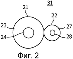
Фиг.2 иллюстрирует в поперечном разрезе первый вариант осуществления кабеля согласно изобретению.Figure 2 illustrates in cross section a first embodiment of a cable according to the invention.
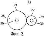
Фиг.3 иллюстрирует в поперечном разрезе второй вариант осуществления кабеля согласно изобретению.Figure 3 illustrates in cross section a second embodiment of a cable according to the invention.
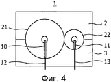
Фиг.4 иллюстрирует в поперечном разрезе второй вариант осуществления разъема с фиксацией согласно изобретению в закрытом положении, содержащего кабель согласно изобретению.Figure 4 illustrates in cross section a second embodiment of a connector with a latch according to the invention in a closed position containing a cable according to the invention.
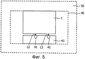
Фиг.5 иллюстрирует устройство согласно изобретению, содержащее схему согласно изобретению.5 illustrates an apparatus according to the invention comprising a circuit according to the invention.
Первый вариант осуществления разъема 1 с фиксацией согласно изобретению, показанный на Фиг.1 в поперечном сечении в открытом положении (левая сторона) и закрытом положении (правая сторона), содержит первую часть 2 и вторую часть 3. Первая часть 2 содержит первый паз 4 и второй паз 5. Вторая часть 3 содержит третий паз 6 и четвертый паз 7. Первый и третий пазы 4 и 6 вместе формируют первое отверстие для фиксации первого электрического элемента 21, показанного на Фиг. 2 и 3, а второй и четвертый пазы 5 и 7 вместе формируют второе отверстие для фиксации второго электрического элемента 22, показанного на Фиг.2 и 3, в закрытом положении первой и второй частей 2 и 3.A first embodiment of a locking
Первый контакт 8 в форме первой вилки выступает из первого паза 4 и заострен в направлении третьего паза 6, и второй контакт 9 в форме первой вилки выступает из второго паза 5 и заострен в направлении четвертого паза 7 в закрытом положении первой и второй частей 1 и 2. Петля 14 соединяет первую и вторую части 2 и 3 и позволяет этим первой и второй частям 2 и 3 открываться и закрываться.The first contact 8 in the form of the first plug protrudes from the first groove 4 and is pointed in the direction of the third groove 6, and the second contact 9 in the form of the first plug protrudes from the second groove 5 and is pointed in the direction of the fourth groove 7 in the closed position of the first and
Первый вариант осуществления кабеля 31 согласно изобретению, показанного на Фиг.2, в поперечном сечении содержит первый электрический элемент 21 и второй электрический элемент 22. Первый электрический элемент 21 содержит первый проводник 24, окруженный первым изоляционным слоем 23, и второй электрический элемент 22 содержит второй проводник 28, окруженный вторым изоляционным слоем 27.The first embodiment of the
Второй вариант осуществления кабеля 31 согласно изобретению, показанного на Фиг.2, в поперечном сечении содержит первый электрический элемент 21 и второй электрический элемент 22. Первый электрический элемент 21 содержит первый проводник 26, окруженный первым изоляционным слоем 25, а второй электрический элемент 22 содержит второй проводник 30, окруженный вторым изоляционным слоем 29.The second embodiment of the
Второй вариант осуществления разъема 1 с фиксацией согласно изобретению, показанный на Фиг.4 в закрытом положении и содержащий кабель 31 согласно изобретению, соответствует первому варианту осуществления разъема 1 с фиксацией, показанному на Фиг.1, за исключением того факта, что еще один первый контакт 10 в форме первого штырька выступает из первого паза 4 и заострен в направлении третьего паза 6, а еще один второй контакт 11 в форме второго штырька выступает из второго паза 5 и заострен в направлении четвертого паза 7 в закрытом положении первой и второй частей 1 и 2, при этом петля 14 может присутствовать, а может не присутствовать. Дополнительно, соединения 12 и 13 выводят контакты 10 и 11 наружу из разъема 1 с фиксацией.A second embodiment of the latching
Устройство 50 согласно изобретению, показанное на Фиг.5, содержит схему 40 согласно изобретению. Схема 40 содержит, например, один или более органических или неорганических светоизлучающих диодов 43. Соединения 12 и 13 разъема 1 с фиксацией подсоединены к первому и второму электродам 41 и 42 схемы 40 (либо одному или более органических или неорганических светоизлучающих диодов 43).The
Разъем 1 с фиксацией подсоединяет первый электрод 41 схемы 40, показанной на Фиг.5, к первому электрическому элементу 21, имеющему размер первого элемента, и подсоединяет второй электрод 42 схемы 40 ко второму электрическому элементу 22, имеющему размер второго элемента, который меньше размера первого элемента. Разъем 1 с фиксацией, кроме того, содержит первый паз 4 для направления первого электрического элемента 21 и второй паз 5 для направления второго электрического элемента 22. Соответствующие первый и второй пазы 4 и 5, помимо этого, содержат соответствующие первое и второе средство для соединения, с одной стороны, первого паза 4 и первого электрического элемента 21 и, с другой стороны, второго паза 5 и второго электрического элемента 22 невзаимозаменяемым способом.The latching
Согласно первому варианту первое средство - это размер первого паза, а второе средство - это размер второго паза, который меньше чем размер первого пара. В этом случае первый и второй электрические элементы 21 и 22 могут быть параллельными электрическими элементами, причем размеры первого и второго элементов могут быть размерами в указанной плоскости, параллельной поперечному сечению электрических элементов 21 и 22, и размеры первого и второго пазов могут быть размерами в плоскости. Размеры первого и второго элементов могут диаметрами, и первый паз 4 может иметь первую искривленную форму, такую как форма половины первой окружности, а второй паз 5 может иметь вторую искривленную форму, такую как форма половины второй окружности, и размер первого паза может быть диаметром первой окружности, а размер второго паза может быть диаметром второй окружности.According to the first embodiment, the first means is the size of the first groove, and the second means is the size of the second groove, which is smaller than the size of the first pair. In this case, the first and second
Разность между размером первого паза и размером второго электрического элемента предпочтительно может быть больше, чем разность между размером первого паза и размером первого электрического элемента, а разность между размером второго паза и размером первого электрического элемента предпочтительно может быть больше, чем разность между размером второго паза и размером второго электрического элемента.The difference between the size of the first groove and the size of the second electrical element may preferably be larger than the difference between the size of the first groove and the size of the first electrical element, and the difference between the size of the second groove and the size of the first electrical element may preferably be larger than the difference between the size of the second groove and the size of the second electrical element.
Для этого первого варианта петля 14 предпочтительно может размещаться ближе ко второму и четвертому пазам 5 и 7, чем к первому и третьему пазам 4 и 6. Размером первого элемента может быть диаметр комбинации первого проводника 24 или 26 и первого изоляционного слоя 23 или 25, а размером второго элемента может быть диаметр комбинации второго проводника 28 или 30 и второго изоляционного слоя 27 или 29. Диаметр первого проводника 26 предпочтительно практически равен диаметру второго проводника 30, а толщина первого изоляционного слоя 25 предпочтительно больше, чем толщина второго изоляционного слоя 29. Альтернативно, первый электрический элемент 21 может содержать в себе первый (гибкий или негибкий) проводник, а второй электрический элемент 22 может содержать в себе второй (гибкий или негибкий) проводник, причем изоляционный слой, например, размещается между ними, и при этом размером первого элемента может быть диаметр первого проводника, а размером второго элемента может быть диаметр второго проводника.For this first embodiment, the loop 14 may preferably be located closer to the second and fourth grooves 5 and 7 than to the first and third grooves 4 and 6. The size of the first element may be the combination diameter of the
Согласно второму варианту первое средство содержит первый контакт 8 или 10, который выступает из первого паза 4, а второе средство содержит второй контакт 9 или 11, который выступает из второго паза 5, при этом первый контакт 8 или 10 имеет размер первого контакта, а второй контакт 9 или 11 имеет размер второго контакта, который меньше, чем размер первого контакта. Эти размеры контактов могут содержать длину штырька или толщину штырька, или длину вилки, или промежуток между ножками вилки и т.д.According to the second embodiment, the first means comprises a
Кабель 31 содержит первый электрический элемент 21, имеющий размер первого элемента, и второй электрический элемент 22, имеющий размер второго элемента, который меньше размера первого элемента. Эти первый и второй электрические элементы 21 и 22 в случае формирования части кабеля являются параллельными электрическими элементами, причем размеры первого и второго элементов являются размерами в плоскости, параллельной поперечному сечению электрических элементов 21 и 22.
Альтернативно, комбинация первого электрического элемента 21, имеющего размер первого элемента, и второго электрического элемента, имеющего размер второго элемента, который меньше размера первого элемента, и разъема 1 с фиксацией для подсоединения первого электрода 41 схемы 40 к первому электрическому элементу 21 и для подсоединения второго электрода 42 схемы 40 ко второму электрическому элементу 22 может иметь первый паз 4, размещенный в разъеме 1 с фиксацией, для направления первого электрического элемента 21 и может иметь второй паз 5, размещенный в разъеме 1 с фиксацией, для направления второго электрического элемента 22, причем соответствующие первый и второй пазы 4 и 5 могут содержать соответствующие первое и второе средство для соединения первого паза 4 и первого электрического элемента 21 и для соединения второго паза 5 и второго электрического элемента 22 невзаимозаменяемым способом. Из этой комбинации первый и второй электрические элементы 21 и 22, с одной стороны, и разъем 1 с фиксацией, с другой стороны, могут создаваться и/или продаваться по отдельности.Alternatively, a combination of a first
Дополнительно, в разъеме 1 с фиксацией согласно изобретению первое и второе средства имеют первый и второй размеры первого и второго пазов 4 и 5 и/или имеют первый и второй размеры частей первого и второго пазов, таких как первый и второй контакты 8, 10 и 9, 11. Другими словами, соответствующие первое и второе средства являются соответствующими первым и вторым размерами, причем первый и второй размеры являются различными размерами.Additionally, in the locking
Каждый электрический элемент 21 или 22 может быть гибким элементом или негибким элементом для передачи одного или более электрических сигналов. Эти электрические сигналы могут содержать в себе один или более сигналов напряжения и/или один или более сигналов тока. Эти электрические сигналы могут быть постоянными в течение одного или более временных интервалов или могут быть изменяющимися в течение одного или более временных интервалов.Each
Обобщая, общераспространен недорогой разъем с фиксацией по предшествующему уровню техники. Его корпус подходит для кабеля. Металлический штырек или вилка может проникать через изоляцию кабеля, чтобы осуществлять электрическое соединение. Преимущество такого разъема с фиксацией состоит в том, что он может быть помещен в каждую позицию кабеля, и что парной детали не требуется. Тем не менее, эти разъемы с фиксацией по предшествующему уровню техники могут быть установлены в двух направлениях и тем самым неприменимы для вариантов применения с полюсами. OLED (органический светоизлучающий диод) является чувствительным к полюсу компонентом (как диод) и тем самым не подходит для разъема с фиксацией по предшествующему уровню техники.Summarizing, it is a common inexpensive connector with a fixation in the prior art. Its housing is suitable for cable. A metal pin or plug can penetrate the cable insulation to make an electrical connection. The advantage of such a fixed connector is that it can be placed in each position of the cable, and that no paired part is required. However, these prior artly fixed connectors can be installed in two directions and thus are not applicable for pole applications. OLED (Organic Light Emitting Diode) is a pole sensitive component (like a diode) and is therefore not suitable for a prior art locking connector.
Если диаметры кабеля для положительного провода и отрицательного провода отличаются друг от друга, то создается физическая разность. Если корпус разъема с фиксацией изготовлен с большим отверстием и с небольшим отверстием, то этот кабель вставляется только согласно одному варианту. Это может быть использовано для поляризации. Комбинация провода и разъема должна делать систему уникальной и простой в использовании. Кабель может монтироваться в комнате (к примеру, в плинтус). Далее OLED может быть размещен в любом месте, где требуется, и тогда разъем с фиксацией может быть применен к кабелю без подготовки. После того как OLED более не требуется, то разъем может быть вынут, и кабель по-прежнему остается нетронутым. Форма вилки может быть сделана безопасной для детей. Разъем также может быть использован для других поляризованных вариантов применения. Следует отметить, что вышеуказанные варианты осуществления иллюстрируют, а не ограничивают изобретение, и специалисты в данной области техники должны иметь возможность проектировать множество альтернативных вариантов осуществления без отступления от области применения прилагаемой формулы изобретения. В формуле изобретения все номера ссылок, помещенные в круглые скобки, не должны рассматриваться как ограничивающие формулу изобретения. Использование глагола "содержать" и его спряжений не исключает наличия элементов или этапов, отличных от указанных в формуле изобретения. Артикль "a" или "an" перед элементом не исключает наличия множества таких элементов. В пункте формулы изобретения по устройству, перечисляющем несколько средств, некоторые из этих средств могут быть осуществлены посредством одного и того же элемента аппаратных средств. Простой факт того, что определенные признаки упомянуты в различных зависимых пунктах формулы изобретения, не означает того, чтобы комбинация этих признаков не может быть использована с выгодой.If the cable diameters for the positive wire and the negative wire are different from each other, a physical difference is created. If the housing of the locking connector is made with a large hole and with a small hole, then this cable is inserted only according to one option. This can be used for polarization. The combination of wire and connector should make the system unique and easy to use. The cable can be mounted in a room (for example, in the baseboard). Further, OLED can be placed anywhere where required, and then the fixed connector can be applied to the cable without preparation. After OLED is no longer required, the connector can be removed and the cable is still intact. The shape of the plug can be made safe for children. The connector can also be used for other polarized applications. It should be noted that the above embodiments illustrate and do not limit the invention, and those skilled in the art should be able to design many alternative embodiments without departing from the scope of the attached claims. In the claims, all reference numbers placed in parentheses should not be construed as limiting the claims. The use of the verb "contain" and its conjugations does not exclude the presence of elements or steps other than those specified in the claims. The article “a” or “an” before an element does not exclude the presence of many such elements. In a claim on a device listing several means, some of these means may be implemented by the same hardware element. The mere fact that certain features are mentioned in the various dependent claims does not mean that a combination of these features cannot be used to advantage.
Claims (16)
Applications Claiming Priority (2)
| Application Number | Priority Date | Filing Date | Title |
|---|---|---|---|
| EP06113262.7 | 2006-04-28 | ||
| EP06113262 | 2006-04-28 |
Publications (2)
| Publication Number | Publication Date |
|---|---|
| RU2008146990A RU2008146990A (en) | 2010-06-10 |
| RU2408959C2 true RU2408959C2 (en) | 2011-01-10 |
Family
ID=38349562
Family Applications (1)
| Application Number | Title | Priority Date | Filing Date |
|---|---|---|---|
| RU2008146990/07A RU2408959C2 (en) | 2006-04-28 | 2007-04-19 | Locked connector |
Country Status (8)
| Country | Link |
|---|---|
| US (1) | US7766687B2 (en) |
| EP (1) | EP2016646A1 (en) |
| JP (1) | JP2009535762A (en) |
| KR (1) | KR20090013807A (en) |
| CN (1) | CN101432929A (en) |
| RU (1) | RU2408959C2 (en) |
| TW (1) | TW200814472A (en) |
| WO (1) | WO2007125463A1 (en) |
Families Citing this family (15)
| Publication number | Priority date | Publication date | Assignee | Title |
|---|---|---|---|---|
| US8025521B2 (en) * | 2008-07-01 | 2011-09-27 | Hubbell Incorporated | Electrical connector |
| ES2393466B1 (en) * | 2011-06-08 | 2013-07-01 | Simon, S.A.U. | ELECTRICAL CONTACT |
| CN102509910B (en) * | 2011-10-20 | 2014-08-20 | 华为技术有限公司 | Jointing clamp |
| TWI532261B (en) * | 2012-08-28 | 2016-05-01 | 隆達電子股份有限公司 | Connector and lighting device having the same |
| ITTO20120820A1 (en) * | 2012-09-21 | 2014-03-22 | Schneider Electric Ind Sas | DOOR-CONTACT GROUP FOR AN ELECTRICAL CONNECTION SOCKET / PLUG |
| CN103812072B (en) * | 2012-11-15 | 2017-03-15 | 国家电网公司 | Cable buckling |
| JP2014146484A (en) * | 2013-01-29 | 2014-08-14 | Yazaki Corp | Connection structure of electric component |
| JP6050196B2 (en) * | 2013-08-09 | 2016-12-21 | 株式会社オートネットワーク技術研究所 | Wire harness and connector |
| CN104464975B (en) * | 2014-12-23 | 2017-02-01 | 天津塑力线缆集团有限公司 | Repair device for weak-current low-voltage electric wire and cable insulation defect |
| CN106099403B (en) * | 2016-06-21 | 2018-05-22 | 国网河南省电力公司郑州供电公司 | A kind of cable insulation penetrating cable clamp |
| CN106637828A (en) * | 2016-11-25 | 2017-05-10 | 青岛海尔洗衣机有限公司 | Hook, control disc base and washing machine |
| US10756461B2 (en) | 2017-05-30 | 2020-08-25 | Erico International Corporation | Adapter for splice block openings |
| US11047414B2 (en) | 2018-05-10 | 2021-06-29 | Craig Davis Adams | Metal lashing plates |
| CN111266667B (en) * | 2018-12-04 | 2021-10-19 | 怀化市恒裕实业有限公司 | Chamfering device for gear ring machining |
| TWI757862B (en) * | 2020-09-08 | 2022-03-11 | 台達電子工業股份有限公司 | Power connector and cable supporting base thereof |
Family Cites Families (14)
| Publication number | Priority date | Publication date | Assignee | Title |
|---|---|---|---|---|
| US3845236A (en) * | 1973-06-21 | 1974-10-29 | Minnesota Mining & Mfg | Wire connector |
| CA1072649A (en) * | 1976-01-07 | 1980-02-26 | Robert H. Frantz | Insulated electrical connector housing |
| US4138184A (en) * | 1978-03-06 | 1979-02-06 | Amp Incorporated | Terminating means for a multi-wire cable |
| JPS6331337Y2 (en) * | 1979-12-27 | 1988-08-22 | ||
| US4508399A (en) * | 1984-01-03 | 1985-04-02 | Amp Incorporated | Polarized ribbon cable connector having circuit components therein |
| FR2665803B1 (en) * | 1990-08-09 | 1993-06-18 | Labinal | BYPASS CONNECTOR. |
| US5338220A (en) * | 1992-05-19 | 1994-08-16 | The Whitaker Corporation | Electrical connector housing assembly and an electrical terminal therefor |
| DE69330866T2 (en) | 1992-12-26 | 2002-05-02 | Sumitomo Wiring Systems | Insulation displacement connector |
| US5944463A (en) * | 1997-07-22 | 1999-08-31 | Savage, Jr.; John M. | Clamp connection of electrical wiring and electrical lead structure |
| GB0114976D0 (en) * | 2001-06-19 | 2001-08-08 | Koninkl Philips Electronics Nv | Cable |
| JP3924187B2 (en) * | 2002-03-20 | 2007-06-06 | 矢崎総業株式会社 | connector |
| US6827600B2 (en) * | 2002-03-20 | 2004-12-07 | Yazaki Corporation | Paired electrical cable connector |
| GB2409332B (en) | 2003-08-14 | 2006-12-13 | Richard Peter James Barton | Lamp assembly for direct connection to system wiring |
| JP2005093900A (en) | 2003-09-19 | 2005-04-07 | Yazaki Corp | Led lamp module, and manufacturing method thereof |
-
2007
- 2007-04-19 CN CNA2007800153804A patent/CN101432929A/en active Pending
- 2007-04-19 WO PCT/IB2007/051419 patent/WO2007125463A1/en active Application Filing
- 2007-04-19 US US12/298,142 patent/US7766687B2/en not_active Expired - Fee Related
- 2007-04-19 KR KR1020087028928A patent/KR20090013807A/en not_active Application Discontinuation
- 2007-04-19 EP EP07735555A patent/EP2016646A1/en not_active Withdrawn
- 2007-04-19 RU RU2008146990/07A patent/RU2408959C2/en not_active IP Right Cessation
- 2007-04-19 JP JP2009507222A patent/JP2009535762A/en active Pending
- 2007-04-25 TW TW096114643A patent/TW200814472A/en unknown
Also Published As
| Publication number | Publication date |
|---|---|
| US20090078445A1 (en) | 2009-03-26 |
| JP2009535762A (en) | 2009-10-01 |
| EP2016646A1 (en) | 2009-01-21 |
| CN101432929A (en) | 2009-05-13 |
| WO2007125463A1 (en) | 2007-11-08 |
| RU2008146990A (en) | 2010-06-10 |
| KR20090013807A (en) | 2009-02-05 |
| US7766687B2 (en) | 2010-08-03 |
| TW200814472A (en) | 2008-03-16 |
Similar Documents
| Publication | Publication Date | Title |
|---|---|---|
| RU2408959C2 (en) | Locked connector | |
| JP4537416B2 (en) | Electrical contact | |
| US8840434B2 (en) | Rotatable plug-type connector | |
| US20130137310A1 (en) | Plug connector for differential data transmission | |
| CN104701672B (en) | Heat Resistant Magnetic Electrical Connector | |
| JP2009539224A (en) | Magnetic connector for coaxial cable | |
| US7086892B2 (en) | Live circuit indicator for plugs and receptacles | |
| TWI594522B (en) | Plug | |
| CN104247156B (en) | Insulating body of a plug connector | |
| US9912081B2 (en) | Lighted electrical connector housing | |
| US20220329026A1 (en) | Serially-connectable device for electrical cable | |
| TW201807895A (en) | Plug connector | |
| CA2921403A1 (en) | Multi-piece jacket for separable connectors | |
| US6932639B2 (en) | Electroluminescent cable connector | |
| EP1166400B1 (en) | Electrical connector | |
| US20120164861A1 (en) | Safety socket | |
| TWM512225U (en) | Power supply connector and its conductive terminal | |
| GB2560864A8 (en) | Spliced electrical connector | |
| CN109792118B (en) | Connector with a locking member | |
| ES2753255T3 (en) | Assembly of a connecting cable and a connecting device and method of assembling it | |
| TWM499677U (en) | Probe type connector with anti-interference mechanism | |
| US5683265A (en) | Barrel plug having insulation displacement terminals | |
| US9979124B2 (en) | Plug-securing connecting apparatus and socket | |
| CN109621456B (en) | Building block | |
| TWM537323U (en) | Improved structure of power connector |
Legal Events
| Date | Code | Title | Description |
|---|---|---|---|
| MM4A | The patent is invalid due to non-payment of fees |
Effective date: 20120420 |