RU2408321C2 - Medical instrument for nerve projection locating in nerve block anaesthesia - Google Patents
Medical instrument for nerve projection locating in nerve block anaesthesia Download PDFInfo
- Publication number
- RU2408321C2 RU2408321C2 RU2009105296/14A RU2009105296A RU2408321C2 RU 2408321 C2 RU2408321 C2 RU 2408321C2 RU 2009105296/14 A RU2009105296/14 A RU 2009105296/14A RU 2009105296 A RU2009105296 A RU 2009105296A RU 2408321 C2 RU2408321 C2 RU 2408321C2
- Authority
- RU
- Russia
- Prior art keywords
- ruler
- slot
- bolt
- medical instrument
- sponge
- Prior art date
Links
- 210000005036 nerve Anatomy 0.000 title abstract description 13
- 206010002091 Anaesthesia Diseases 0.000 title 1
- 230000037005 anaesthesia Effects 0.000 title 1
- 238000001949 anaesthesia Methods 0.000 title 1
- 239000002390 adhesive tape Substances 0.000 claims description 8
- 230000014759 maintenance of location Effects 0.000 claims description 8
- 239000003814 drug Substances 0.000 abstract description 7
- 229940053973 novocaine Drugs 0.000 abstract description 3
- MFDFERRIHVXMIY-UHFFFAOYSA-N procaine Chemical compound CCN(CC)CCOC(=O)C1=CC=C(N)C=C1 MFDFERRIHVXMIY-UHFFFAOYSA-N 0.000 abstract description 3
- 239000000126 substance Substances 0.000 abstract 1
- 210000000988 bone and bone Anatomy 0.000 description 12
- 230000015572 biosynthetic process Effects 0.000 description 6
- 210000001519 tissue Anatomy 0.000 description 6
- 210000002414 leg Anatomy 0.000 description 4
- 238000000034 method Methods 0.000 description 4
- 238000005259 measurement Methods 0.000 description 3
- 208000027418 Wounds and injury Diseases 0.000 description 2
- 230000006378 damage Effects 0.000 description 2
- 229940079593 drug Drugs 0.000 description 2
- 210000000527 greater trochanter Anatomy 0.000 description 2
- 208000014674 injury Diseases 0.000 description 2
- 238000011089 mechanical engineering Methods 0.000 description 2
- 230000007423 decrease Effects 0.000 description 1
- 238000006073 displacement reaction Methods 0.000 description 1
- 210000003692 ilium Anatomy 0.000 description 1
- 210000002239 ischium bone Anatomy 0.000 description 1
- 210000003205 muscle Anatomy 0.000 description 1
- 238000002559 palpation Methods 0.000 description 1
- 210000002784 stomach Anatomy 0.000 description 1
- 208000011580 syndromic disease Diseases 0.000 description 1
- 210000000689 upper leg Anatomy 0.000 description 1
Images
Landscapes
- Media Introduction/Drainage Providing Device (AREA)
- Orthopedics, Nursing, And Contraception (AREA)
Abstract
Description
Изобретение относится к медицине, в частности к неврологии, для проведения новокаиновой блокады.The invention relates to medicine, in particular to neurology, for novocaine blockade.
Известно медицинское устройство, включающее планку с размещенными на ней рамками губок, обращенных в одну сторону от планки, и размещенную в середине планки муфту, причем муфта и рамки выполнены с возможностью перемещения их вдоль планки (А.В.Каплан. Закрытые повреждения костей и суставов. Второе издание. М.: Медицина, 1967. С. 82-83).A medical device is known that includes a bar with sponge frames placed on it facing one side of the bar and a sleeve located in the middle of the bar, the clutch and frames being able to move them along the bar (A.V. Kaplan. Closed injuries to bones and joints Second Edition, Moscow: Medicine, 1967. P. 82-83).
Недостатком этого устройства является отсутствие в нем признаков повышения точности определения на коже в сагиттальной плоскости проекции нерва или иного образования, находящегося в тканях организма относительно пальпаторно доступных внешних костных ориентиров.The disadvantage of this device is the lack of signs in it of improving the accuracy of determining on the skin in the sagittal plane the projection of a nerve or other formation located in the tissues of the body relative to the palpatory accessible external bone landmarks.
Известен медицинский инструмент - трехстворчатый ранорасширитель, включающий две ручки, соединенные между собой в средней части осью в виде винта, на нерабочем конце одной из ручек прикреплена дугообразная кремальера с возможностью перемещения вдоль нее другой ручки (Ю.Ф.Кабатов. Медицинский инструментарий, аппаратура и оборудование. М.: Медицина, 1977, стр.126-128, рис.27-А).A well-known medical tool is a tricuspid retractor, which includes two handles connected in the middle part by an axis in the form of a screw, an arc-shaped cremalera is attached to the non-working end of one of the handles with the ability to move the other handle along it (Yu.F. Kabatov. Medical instruments, equipment and equipment.M.: Medicine, 1977, pp. 126-128, Fig. 27-A).
Недостатком этого устройства является отсутствие в нем признаков повышения точности определения на коже в сагиттальной плоскости проекции нерва или иного образования, находящегося в тканях организма относительно пальпаторно доступных внешних костных ориентиров.The disadvantage of this device is the lack of signs in it of increasing the accuracy of determining on the skin in the sagittal plane the projection of a nerve or other formation located in the tissues of the body relative to the palpatory accessible external bone landmarks.
Известен кронциркуль, состоящий из двух одинаковой длины ножек, верхними концами соединенных между собой общей осью, причем рабочие концы ножек направлены навстречу друг другу. Кронциркуль служит для измерения расстояний между наружными поверхностями различных предметов, им можно измерять и размеры диаметров наружных отверстий каналов (Суворов С.Г., Суворов Н.С. Машиностроительное черчение в вопросах и ответах. Справочник. М.: Машиностроение, 1984. С. 39-40).A caliper is known, consisting of two equal lengths of legs, the upper ends of which are interconnected by a common axis, and the working ends of the legs are directed towards each other. The caliper serves to measure the distances between the outer surfaces of various objects, they can also measure the diameters of the outer openings of the channels (Suvorov S.G., Suvorov N.S. Mechanical engineering drawing in questions and answers. Handbook. M .: Mechanical engineering, 1984. P. 39-40).
Недостатком является отсутствие в его конструкции линейки, без которой снижается точность измерения или она становится даже невозможной. После измерения канала необходимо отложить полученный размер на шкале другого устройства - линейки, на что требуется дополнительная затрата времени. При перемещении кронциркуля от объекта измерения к линейке возможно изменение расстояния между его ножками, что снижает надежность измерения. Недостатком кронциркуля является отсутствие в нем признаков повышения точности определения на коже в сагиттальной плоскости проекции нерва или иного образования, находящегося в тканях организма относительно пальпаторно доступных внешних костных ориентиров.The disadvantage is the lack of a ruler in its design, without which the accuracy of the measurement decreases or it even becomes impossible. After measuring the channel, it is necessary to postpone the received size on the scale of another device - a ruler, which requires an additional expenditure of time. When the caliper moves from the measurement object to the ruler, it is possible to change the distance between its legs, which reduces the reliability of the measurement. A drawback of the calipers is the lack of signs in it of increasing the accuracy of determining the projection of a nerve or other formation located on the skin in the tissues of the body relative to the palpatory accessible external bone landmarks on the skin in the sagittal plane.
Известен штангенциркуль, состоящий из линейки с метрическими делениями на ней и двух измерительных губок одинаковой длины, рабочие поверхности которых направлены в противоположные стороны, верхними концами соединенных между собой общей осью, причем рабочие концы ножек направлены навстречу друг другу. На противоположной стороне линейки выполнены похожие губки, но с рабочими поверхностями, обращенными навстречу друг другу. Причем по одной из губок на каждой стороне линейки размещены на рамке нониуса. Штангенциркуль служит как для измерения расстояний между наружными поверхностями различных предметов измерительными губками, так и для измерения размеров диаметров отверстий каналов с помощью губок. Для фиксации рамки штангенциркуль содержит микрометрический винт (Суворов С.Г., Суворов Н.С. Там же. С. 39-40).A caliper is known, consisting of a ruler with metric divisions on it and two measuring jaws of the same length, the working surfaces of which are directed in opposite directions, the upper ends of which are connected by a common axis, with the working ends of the legs directed towards each other. On the opposite side of the line are similar sponges, but with working surfaces facing towards each other. Moreover, one of the sponges on each side of the ruler is placed on the vernier frame. The caliper serves both for measuring the distances between the outer surfaces of various objects with measuring jaws, and for measuring the dimensions of the diameters of the channel openings using jaws. To fix the frame, the caliper contains a micrometer screw (Suvorov S.G., Suvorov N.S. ibid., Pp. 39-40).
Недостатком штангенциркуля является небольшая длина измерительных губок, из-за чего ими невозможно измерить проекции костных ориентиров в одной горизонтальной плоскости при расположении костных выступов на разной высоте тела пациента. Недостатком этого устройства является также отсутствие в нем признаков повышения точности определения на коже в сагиттальной плоскости проекции нерва или иного образования, находящегося в тканях организма относительно пальпаторно доступных внешних костных ориентиров.A drawback of the caliper is the small length of the measuring jaws, which makes it impossible to measure the projections of the bone landmarks in the same horizontal plane when the bone protrusions are located at different heights of the patient's body. The disadvantage of this device is the lack of signs in it of improving the accuracy of determining on the skin in the sagittal plane the projection of a nerve or other formation located in the tissues of the body relative to the palpatory accessible external bone landmarks.
Наиболее близким по технической сущности к предлагаемому медицинскому инструменту является устройство, описанное последним, которое принято за прототип, а недостатки его изложены выше.The closest in technical essence to the proposed medical instrument is the device described by the latter, which is taken as a prototype, and its disadvantages are described above.
Технический результат изобретения заключается в повышении точности определения на коже в сагиттальной плоскости проекции нерва или иного образования, находящегося в тканях организма относительно пальпаторно доступных внешних костных ориентиров.The technical result of the invention is to increase the accuracy of determination on the skin in the sagittal plane of the projection of a nerve or other formation located in the tissues of the body relative to the palpatory accessible external bone landmarks.
Технический результат достигается тем, что медицинский инструмент для определения проекции нерва при проводниковых блокадах содержит линейку с метрическими делениями и соединенные с ней верхними концами под прямым углом две параллельные губки, рабочие концы которых направлены в одну сторону. Одна из губок прикреплена к концу линейки неподвижно, а другая размещена на рамке с возможностью перемещения вдоль линейки. Инструмент содержит вторую аналогичную линейку, соединенную с первой линейкой с возможностью перемещения и фиксации ее в одной с ней горизонтальной плоскости, причем каждая линейка имеет продольную прорезь с возможностью проведения через нее стержня болта, в центре которого выполнен сквозной продольный канал, при этом каждая рамка содержит канал под винт, диаметр конической головки болта со шлицом превышает верхнюю ширину прорези в первой линейке, а гайка болта расположена над линейками, при этом прорезь в первой линейке на нижней поверхности выполнена более широкой, чем на верхней поверхности с исключением выступания поверхности головки болта из прорези у нижней поверхности линейки.The technical result is achieved by the fact that the medical tool for determining the projection of the nerve during conduction blockade contains a ruler with metric divisions and two parallel jaws connected to it by upper ends at right angles, the working ends of which are directed in one direction. One of the jaws is fixed to the end of the ruler motionless, and the other is placed on the frame with the ability to move along the ruler. The tool contains a second similar ruler connected to the first ruler with the ability to move and fix it in the same horizontal plane, each ruler having a longitudinal slot with the possibility of passing through it a bolt rod, in the center of which a through longitudinal channel is made, each frame contains the channel for the screw, the diameter of the conical head of the bolt with the slot exceeds the upper slot width in the first ruler, and the bolt nut is located above the rulers, while the slot in the first ruler on the bottom ited made wider than the upper surface excluding the surface of the bolt head projecting from the slot at the bottom surface of the ruler.
В предпочтительном варианте продольно на каждой линейке размещен уровень.In a preferred embodiment, a level is placed longitudinally on each line.
В другом предпочтительном варианте рабочий конец губки на каждой линейке содержит элемент удержания губки на коже пациента.In another preferred embodiment, the working end of the sponge on each ruler comprises a sponge retention element on the patient's skin.
В следующем предпочтительном варианте элемент удержания на коже выполнен из липкой ленты с прикрепленной в средней ее части трубкой под рабочий конец губки.In a further preferred embodiment, the skin retention element is made of adhesive tape with a tube attached in its middle part under the working end of the sponge.
В последнем предпочтительном варианте метрические деления на верхней поверхности линеек выполнены с отсчетом от неподвижных губок.In the latter preferred embodiment, the metric divisions on the upper surface of the rulers are counted from the fixed jaws.
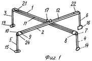
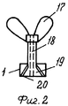
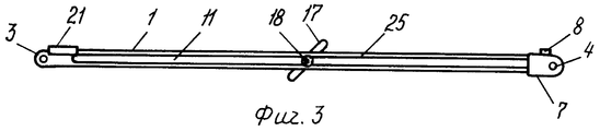
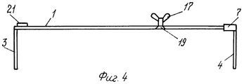
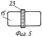
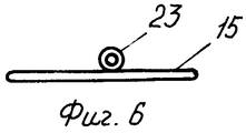
Сущность технического решения поясняется чертежами. На фиг.1 изображен медицинский инструмент в собранном виде; на фиг.2 - деталь устройства - болт с гайкой; на фиг.3 - деталь устройства - линейка, вид сверху; на фиг.4 - та же деталь устройства, вид сбоку; на фиг.5 - деталь устройства - элемент удержания губок устройства на теле пациента, вид сбоку; на фиг.6 - та же деталь устройства, вид сверху. На фиг.1-6 обозначены: 1 - первая линейка, нижняя, 2 - вторая линейка, верхняя, 3 - неподвижная губка первой нижней линейки, 4 - подвижная губка первой нижней линейки, 5 - подвижная губка второй верхней линейки, 6 - неподвижная губка второй верхней линейки, 7 - рамка первой нижней линейки, 8 - винт рамки первой нижней линейки; 9 - винт рамки второй верхней линейки; 10 - рамка второй верхней линейки, 11 - продольная прорезь в первой нижней линейке; 12 - продольная прорезь во второй верхней линейке; 13 - элемент удержания неподвижной губки 3 первой нижней линейки; 14 - элемент удержания подвижной губки 4 первой нижней линейки; 15 - липкая лента элемента удержания подвижной губки 5 второй верхней линейки; 16 - элемент удержания неподвижной губки 6 второй верхней линейки; 17 - гайка болта; 18 - продольный канал в стержне болта; 19 - коническая головка болта; 20 - стенка косой продольной прорези 11 в линейке; 21 - уровень на линейке 1; 22 - уровень на линейке 2; 23 - трубка элемента удержания под губку; 24 - фиксатор подвижной губки 4 в рамке 7; 25 - метрические деления на верхней поверхности линейки.The essence of the technical solution is illustrated by drawings. In Fig.1 shows a medical instrument in assembled form; figure 2 - detail of the device is a bolt with a nut; figure 3 - detail of the device is a ruler, top view; figure 4 is the same part of the device, side view; figure 5 - detail of the device is an element of retention of the jaws of the device on the patient's body, side view; figure 6 is the same part of the device, top view. 1-6 are marked: 1 - first ruler, lower, 2 - second ruler, upper, 3 - fixed sponge of the first lower ruler, 4 - movable sponge of the first lower ruler, 5 - movable sponge of the second upper ruler, 6 - fixed sponge the second upper ruler, 7 - the frame of the first lower ruler, 8 - the screw of the frame of the first lower ruler; 9 - frame screw of the second upper ruler; 10 - the frame of the second upper ruler, 11 - a longitudinal slot in the first lower ruler; 12 - a longitudinal slot in the second upper ruler; 13 - element holding the
Конкретный пример пользования устройством, например, у больного с синдромом средней ягодичной мышцы с наличием в ней триггера для проведения блокады среднего ягодичного нерва при подходе сзади. Ранее было установлено, что проекция среднего ягодичного нерва в сагиттальной плоскости при подходе сзади лежит в точке пересечения двух линий, одна из которых проходит через проекцию на горизонтальной плоскости нижней точки седалищной кости и через проекцию наивысшей точки гребня одноименной стороны подвздошной кости и другая - через проекцию латерального выступа большого вертела той же стороны в направлении проекции нижнего края остистого отростка четвертого поясничного позвонка. Больного укладывают в горизонтальном положении на живот. Через продольные прорези 11 и 12 в линейке 1 и в линейке 2 вводят снизу стержень 18 болта и гайкой-барашком 17 удерживают болт в прорезях линеек. Конец неподвижной губки 3 линейки 1 вводят в трубку 23 элемента удержания, прикладывают его к наивысшей точке гребня одноименной стороны подвздошной кости и прикрепляют липкой лентой 13 к коже. Перемещая по линейке 1 рамку 7, конец второй подвижной губки 4 также вводят в другую трубку элемента удержания, прикладывают к нижней точке на седалищной кости и прикрепляют липкой лентой 14 к коже. Верхнюю линейку 2 на стержне болта, как на оси, можно поворачивать относительно нижней линейки и в горизонтальной плоскости изменять расположение губок 5 и 6. Конец неподвижной губки 6 второй линейки 2 вводят в собственную трубку элемента удержания, прикладывают к латеральному выступу большого вертела одноименной стороны и прикрепляют липкой лентой 16 к коже. Конец второй подвижной губки 5 также вводят в другую трубку элемента удержания. Перемещая по линейке 2 рамку 10, прикладывают конец губки 5 к нижнему краю остистого отростка четвертого поясничного позвонка и прикрепляют липкой лентой 15 к коже. При необходимости укорочения рабочей части подвижной губки, направляемой на остистый отросток позвонка, губку придвигают по вертикальному каналу в рамке и на должной высоте закрепляют фиксатором 24. Пользуясь уровнями 21 и 22, устанавливают линейки 1 и 2 в одной горизонтальной плоскости и скрепляют между собой, закручивая гайку 17 болта. Через продольный канал 18 по центру стержня болта, находящегося в проекции пересечения обеих линеек 1 и 2, на коже делают метку проекции в сагиттальном направлений среднего ягодичного нерва.A specific example of using the device, for example, in a patient with middle gluteal muscle syndrome with a trigger in it to block the middle gluteal nerve when approaching from behind. Previously it was found that the projection of the middle gluteal nerve in the sagittal plane when approaching from behind lies at the intersection of two lines, one of which passes through the projection on the horizontal plane of the lower point of the ischium and through the projection of the highest point of the crest of the same side of the ilium and the other through the projection lateral protrusion of the greater trochanter of the same side in the direction of projection of the lower edge of the spinous process of the fourth lumbar vertebra. The patient is laid horizontally on his stomach. Through the
Существенность отличий заявленного устройства от избранного прототипа заключается в следующем. Наличие в медицинском инструменте второй аналогичной линейки, соединенной с первой линейкой с возможностью перемещения и фиксации ее в одной с ней горизонтальной плоскости, позволяет размещать губки одной линейки на доступных для пальпации костных ориентирах, например, на нижней точке седалищной кости и наивысшей точке гребня подвздошной кости, а другой линейки, - например, на латеральном выступе большого вертела бедренной кости и на нижнем крае остистого отростка четвертого поясничного позвонка. Наличие у каждой линейки продольной прорези позволяет болтом с гайкой скреплять линейки между собой в любом положении в одной плоскости. Это обеспечивает возможность проводить линии на коже пациента и намечать точку перекреста их. Наличие в каждой рамке канала под винт позволяет фиксировать рамку с губкой на линейке в заданном положении. Выполнение у болта головки со шлицом конической формы и с размерами менее нижней части прорези в линейке позволяет погружать головку в прорезь линейки без выступа из-под нижней поверхности линейки, обращенной к коже пациента, что исключает травмирование пациента. Выполнение диаметра головки болта превышающим верхнюю ширину прорези в линейке не позволяет ей выходить из прорези через верхнюю поверхность линейки. Размещение гайки-барашка болта над верхней поверхностью линейки не препятствует плотному контакту линейки с кожей пациента, повышая точность исследования. Высокое расположение гайки-барашка над линейками облегчает пользование ею. Размещение на каждой линейке продольного уровня обеспечивает возможность установки всего инструмента в горизонтальной плоскости. Выполнение в центре болта сквозного продольного канала позволяет через него более точно наносить метку на коже пациента или проводить иглу. Выполнение на рабочем конце губки на каждой линейке элемента удержания губки на коже пациента, в частности, из липкой ленты с прикрепленной в средней ее части трубкой под рабочий конец губки исключает смещение устройства и повышает точность исследования. Наличие метрических делений на верхней поверхности линеек с отсчетом от неподвижных губок позволяет измерять расстояние от неподвижного конца линейки до второй губки этой линейки и перекреста со второй линейкой. Такие отличия заявленного устройства обеспечивают достижение технического результата.The significance of the differences of the claimed device from the selected prototype is as follows. The presence in the medical instrument of a second similar ruler, connected to the first ruler with the ability to move and fix it in the same horizontal plane, allows you to place the lips of one ruler on bone landmarks accessible for palpation, for example, at the lower point of the ischial bone and the highest point of the iliac crest and another line, for example, on the lateral protrusion of the greater trochanter of the femur and on the lower edge of the spinous process of the fourth lumbar vertebra. The presence of a longitudinal slot in each ruler allows the bolt and nut to fasten the rulers together in any position in the same plane. This provides the ability to draw lines on the skin of the patient and mark the point of their intersection. The presence in each frame of the channel for the screw allows you to fix the frame with a sponge on the ruler in a predetermined position. The execution of a head with a slot with a conical shape and with dimensions less than the lower part of the slot in the ruler allows you to immerse the head in the slot of the ruler without a protrusion from under the bottom surface of the ruler facing the patient's skin, which eliminates injury to the patient. The diameter of the bolt head exceeding the upper width of the slot in the ruler does not allow it to exit the slot through the upper surface of the ruler. The placement of the wing nut of the bolt above the upper surface of the ruler does not interfere with the tight contact of the ruler with the patient's skin, increasing the accuracy of the study. The high position of the wing nut above the rulers makes it easy to use. Placing on each line of the longitudinal level provides the ability to install the entire tool in a horizontal plane. Performing in the center of the bolt through the longitudinal channel allows you to more accurately apply a mark on the patient’s skin or hold a needle through it. The execution on the working end of the sponge on each line of the element for holding the sponge on the patient’s skin, in particular, from an adhesive tape with a tube attached to its middle part under the working end of the sponge, eliminates the displacement of the device and increases the accuracy of the study. The presence of metric divisions on the upper surface of the rulers counting from the fixed jaws allows you to measure the distance from the fixed end of the ruler to the second sponge of this ruler and the intersection with the second ruler. Such differences of the claimed device ensure the achievement of a technical result.
Использование изобретенного медицинского инструмента в практической медицине повышает точность определения на коже в сагиттальной плоскости проекций нерва или иного образования, находящегося в тканях организма относительно пальпаторно доступных внешних костных ориентиров, что способствует улучшению качества лечения больных, в частности, проводниковыми новокаиновыми блокадами. Применение изобретения возможно также в ветеринарии.The use of the invented medical instrument in practical medicine increases the accuracy of determining on the skin in the sagittal plane projections of a nerve or other formation located in the tissues of the body relative to the palpatory accessible external bone landmarks, which helps to improve the quality of treatment of patients, in particular, conduction novocaine blockades. The use of the invention is also possible in veterinary medicine.
Claims (6)
Priority Applications (1)
| Application Number | Priority Date | Filing Date | Title |
|---|---|---|---|
| RU2009105296/14A RU2408321C2 (en) | 2009-02-16 | 2009-02-16 | Medical instrument for nerve projection locating in nerve block anaesthesia |
Applications Claiming Priority (1)
| Application Number | Priority Date | Filing Date | Title |
|---|---|---|---|
| RU2009105296/14A RU2408321C2 (en) | 2009-02-16 | 2009-02-16 | Medical instrument for nerve projection locating in nerve block anaesthesia |
Publications (2)
| Publication Number | Publication Date |
|---|---|
| RU2009105296A RU2009105296A (en) | 2010-08-27 |
| RU2408321C2 true RU2408321C2 (en) | 2011-01-10 |
Family
ID=42798291
Family Applications (1)
| Application Number | Title | Priority Date | Filing Date |
|---|---|---|---|
| RU2009105296/14A RU2408321C2 (en) | 2009-02-16 | 2009-02-16 | Medical instrument for nerve projection locating in nerve block anaesthesia |
Country Status (1)
| Country | Link |
|---|---|
| RU (1) | RU2408321C2 (en) |
Citations (2)
| Publication number | Priority date | Publication date | Assignee | Title |
|---|---|---|---|---|
| RU2107459C1 (en) * | 1994-09-29 | 1998-03-27 | Нижегородский государственный научно-исследовательский институт травматологии и ортопедии | Method and device for searching nerves and plexus nervosus |
| CN201223450Y (en) * | 2008-06-06 | 2009-04-22 | 中国人民解放军第三军医大学第一附属医院 | Set rule for nerve blocking anesthesia |
-
2009
- 2009-02-16 RU RU2009105296/14A patent/RU2408321C2/en not_active IP Right Cessation
Patent Citations (2)
| Publication number | Priority date | Publication date | Assignee | Title |
|---|---|---|---|---|
| RU2107459C1 (en) * | 1994-09-29 | 1998-03-27 | Нижегородский государственный научно-исследовательский институт травматологии и ортопедии | Method and device for searching nerves and plexus nervosus |
| CN201223450Y (en) * | 2008-06-06 | 2009-04-22 | 中国人民解放军第三军医大学第一附属医院 | Set rule for nerve blocking anesthesia |
Non-Patent Citations (2)
| Title |
|---|
| МАЛРОЙ МАЙКЛ. Местная анестезия. - М.: Бином, 2003, стр.192-195. * |
| СУВОРОВ С.Г., СУВОРОВ Н.С. Машиностроительное черчение в вопросах и ответах. Справочник. - М.: Машиностроение. - 1984. стр.39-40. * |
Also Published As
| Publication number | Publication date |
|---|---|
| RU2009105296A (en) | 2010-08-27 |
Similar Documents
| Publication | Publication Date | Title |
|---|---|---|
| Weber et al. | The utility of DXA assessment at the forearm, proximal femur, and lateral distal femur, and vertebral fracture assessment in the pediatric population: 2019 ISCD official position | |
| Furlanetto et al. | Validating a postural evaluation method developed using a Digital Image-based Postural Assessment (DIPA) software | |
| ES2327357T3 (en) | DEPTH GALGA. | |
| Hwang et al. | The reliability of the nonradiologic measures of thoracic spine rotation in healthy adults | |
| RU2408321C2 (en) | Medical instrument for nerve projection locating in nerve block anaesthesia | |
| Chawla et al. | The relationship between arm span and height in adult males of North Indian Punjabi population | |
| SU1326244A1 (en) | Apparatus for measuring tne bending of spinal column | |
| CN208942308U (en) | Portable stereotaxic instrument for brain | |
| KR102005811B1 (en) | Animal retraining device for non-invasive imaging of brain activity | |
| CN204839467U (en) | Department of neurology inspects scale | |
| CN205831885U (en) | Thoracolumbar disk pedicle of vertebral arch percutaneous puncture three-dimensional guider | |
| RU2210313C1 (en) | Device for determination of muscular tension | |
| KR200447908Y1 (en) | Most Wanted Blood Level Meter | |
| RU164290U1 (en) | METHOD FOR DIAGNOSTIC OF THE QUANTITY OF SCOLIOTIC DEFORMATION OF THE SPINE | |
| JP4864802B2 (en) | Human body part measuring instrument | |
| RU68879U1 (en) | DEVICE FOR MEASURING CALLS | |
| RU172146U1 (en) | DEVICE FOR ANTHROPOLOGICAL MEASUREMENTS | |
| RU134413U1 (en) | CORNER FOR MEASURING THE VALUE OF AN ARC OF THE SPINE | |
| Kim et al. | Study on Change of Muscle Tone and Stiffness According to Upper Trapezius Mild Pain tf Young Adults. | |
| RU142455U1 (en) | DEVICE FOR MEASURING THE HIP ANGLE FOR CHILDREN IN CHILDREN | |
| CN211325529U (en) | Reset guider | |
| RU24783U1 (en) | COURVIMETER COMBINED WITH AN ANGLOMER | |
| TR2021014103A2 (en) | THREE-DIMENSIONAL ADJUSTABLE PEDICLE SCREW GUIDE TOOL | |
| CN205054459U (en) | Backbone body surface locator | |
| SU42660A1 (en) | Instrument for measuring body parts |
Legal Events
| Date | Code | Title | Description |
|---|---|---|---|
| MM4A | The patent is invalid due to non-payment of fees |
Effective date: 20110217 |