RU2405473C2 - Devices of intravascular occlusion guided by transcutaneous catheter - Google Patents
Devices of intravascular occlusion guided by transcutaneous catheter Download PDFInfo
- Publication number
- RU2405473C2 RU2405473C2 RU2008151964/14A RU2008151964A RU2405473C2 RU 2405473 C2 RU2405473 C2 RU 2405473C2 RU 2008151964/14 A RU2008151964/14 A RU 2008151964/14A RU 2008151964 A RU2008151964 A RU 2008151964A RU 2405473 C2 RU2405473 C2 RU 2405473C2
- Authority
- RU
- Russia
- Prior art keywords
- medical device
- catheter
- occlusion
- diameter
- laa
- Prior art date
Links
Images


Classifications
-
- A—HUMAN NECESSITIES
- A61—MEDICAL OR VETERINARY SCIENCE; HYGIENE
- A61B—DIAGNOSIS; SURGERY; IDENTIFICATION
- A61B17/00—Surgical instruments, devices or methods, e.g. tourniquets
- A61B17/0057—Implements for plugging an opening in the wall of a hollow or tubular organ, e.g. for sealing a vessel puncture or closing a cardiac septal defect
-
- A—HUMAN NECESSITIES
- A61—MEDICAL OR VETERINARY SCIENCE; HYGIENE
- A61B—DIAGNOSIS; SURGERY; IDENTIFICATION
- A61B17/00—Surgical instruments, devices or methods, e.g. tourniquets
- A61B17/12—Surgical instruments, devices or methods, e.g. tourniquets for ligaturing or otherwise compressing tubular parts of the body, e.g. blood vessels, umbilical cord
- A61B17/12022—Occluding by internal devices, e.g. balloons or releasable wires
- A61B17/12027—Type of occlusion
- A61B17/12031—Type of occlusion complete occlusion
-
- A—HUMAN NECESSITIES
- A61—MEDICAL OR VETERINARY SCIENCE; HYGIENE
- A61B—DIAGNOSIS; SURGERY; IDENTIFICATION
- A61B17/00—Surgical instruments, devices or methods, e.g. tourniquets
- A61B17/12—Surgical instruments, devices or methods, e.g. tourniquets for ligaturing or otherwise compressing tubular parts of the body, e.g. blood vessels, umbilical cord
- A61B17/12022—Occluding by internal devices, e.g. balloons or releasable wires
- A61B17/12099—Occluding by internal devices, e.g. balloons or releasable wires characterised by the location of the occluder
- A61B17/12109—Occluding by internal devices, e.g. balloons or releasable wires characterised by the location of the occluder in a blood vessel
-
- A—HUMAN NECESSITIES
- A61—MEDICAL OR VETERINARY SCIENCE; HYGIENE
- A61B—DIAGNOSIS; SURGERY; IDENTIFICATION
- A61B17/00—Surgical instruments, devices or methods, e.g. tourniquets
- A61B17/12—Surgical instruments, devices or methods, e.g. tourniquets for ligaturing or otherwise compressing tubular parts of the body, e.g. blood vessels, umbilical cord
- A61B17/12022—Occluding by internal devices, e.g. balloons or releasable wires
- A61B17/12099—Occluding by internal devices, e.g. balloons or releasable wires characterised by the location of the occluder
- A61B17/12122—Occluding by internal devices, e.g. balloons or releasable wires characterised by the location of the occluder within the heart
-
- A—HUMAN NECESSITIES
- A61—MEDICAL OR VETERINARY SCIENCE; HYGIENE
- A61B—DIAGNOSIS; SURGERY; IDENTIFICATION
- A61B17/00—Surgical instruments, devices or methods, e.g. tourniquets
- A61B17/12—Surgical instruments, devices or methods, e.g. tourniquets for ligaturing or otherwise compressing tubular parts of the body, e.g. blood vessels, umbilical cord
- A61B17/12022—Occluding by internal devices, e.g. balloons or releasable wires
- A61B17/12131—Occluding by internal devices, e.g. balloons or releasable wires characterised by the type of occluding device
- A61B17/12168—Occluding by internal devices, e.g. balloons or releasable wires characterised by the type of occluding device having a mesh structure
- A61B17/12172—Occluding by internal devices, e.g. balloons or releasable wires characterised by the type of occluding device having a mesh structure having a pre-set deployed three-dimensional shape
-
- A—HUMAN NECESSITIES
- A61—MEDICAL OR VETERINARY SCIENCE; HYGIENE
- A61B—DIAGNOSIS; SURGERY; IDENTIFICATION
- A61B17/00—Surgical instruments, devices or methods, e.g. tourniquets
- A61B17/12—Surgical instruments, devices or methods, e.g. tourniquets for ligaturing or otherwise compressing tubular parts of the body, e.g. blood vessels, umbilical cord
- A61B17/12022—Occluding by internal devices, e.g. balloons or releasable wires
- A61B17/12131—Occluding by internal devices, e.g. balloons or releasable wires characterised by the type of occluding device
- A61B17/12168—Occluding by internal devices, e.g. balloons or releasable wires characterised by the type of occluding device having a mesh structure
- A61B17/12177—Occluding by internal devices, e.g. balloons or releasable wires characterised by the type of occluding device having a mesh structure comprising additional materials, e.g. thrombogenic, having filaments, having fibers or being coated
-
- A—HUMAN NECESSITIES
- A61—MEDICAL OR VETERINARY SCIENCE; HYGIENE
- A61F—FILTERS IMPLANTABLE INTO BLOOD VESSELS; PROSTHESES; DEVICES PROVIDING PATENCY TO, OR PREVENTING COLLAPSING OF, TUBULAR STRUCTURES OF THE BODY, e.g. STENTS; ORTHOPAEDIC, NURSING OR CONTRACEPTIVE DEVICES; FOMENTATION; TREATMENT OR PROTECTION OF EYES OR EARS; BANDAGES, DRESSINGS OR ABSORBENT PADS; FIRST-AID KITS
- A61F2/00—Filters implantable into blood vessels; Prostheses, i.e. artificial substitutes or replacements for parts of the body; Appliances for connecting them with the body; Devices providing patency to, or preventing collapsing of, tubular structures of the body, e.g. stents
- A61F2/02—Prostheses implantable into the body
- A61F2/24—Heart valves ; Vascular valves, e.g. venous valves; Heart implants, e.g. passive devices for improving the function of the native valve or the heart muscle; Transmyocardial revascularisation [TMR] devices; Valves implantable in the body
-
- A—HUMAN NECESSITIES
- A61—MEDICAL OR VETERINARY SCIENCE; HYGIENE
- A61B—DIAGNOSIS; SURGERY; IDENTIFICATION
- A61B17/00—Surgical instruments, devices or methods, e.g. tourniquets
- A61B17/0057—Implements for plugging an opening in the wall of a hollow or tubular organ, e.g. for sealing a vessel puncture or closing a cardiac septal defect
- A61B2017/00575—Implements for plugging an opening in the wall of a hollow or tubular organ, e.g. for sealing a vessel puncture or closing a cardiac septal defect for closure at remote site, e.g. closing atrial septum defects
-
- A—HUMAN NECESSITIES
- A61—MEDICAL OR VETERINARY SCIENCE; HYGIENE
- A61B—DIAGNOSIS; SURGERY; IDENTIFICATION
- A61B17/00—Surgical instruments, devices or methods, e.g. tourniquets
- A61B2017/00831—Material properties
- A61B2017/00867—Material properties shape memory effect
-
- A—HUMAN NECESSITIES
- A61—MEDICAL OR VETERINARY SCIENCE; HYGIENE
- A61B—DIAGNOSIS; SURGERY; IDENTIFICATION
- A61B17/00—Surgical instruments, devices or methods, e.g. tourniquets
- A61B17/12—Surgical instruments, devices or methods, e.g. tourniquets for ligaturing or otherwise compressing tubular parts of the body, e.g. blood vessels, umbilical cord
- A61B17/12022—Occluding by internal devices, e.g. balloons or releasable wires
- A61B2017/1205—Introduction devices
- A61B2017/12054—Details concerning the detachment of the occluding device from the introduction device
- A61B2017/12095—Threaded connection
Landscapes
- Health & Medical Sciences (AREA)
- Life Sciences & Earth Sciences (AREA)
- Surgery (AREA)
- Veterinary Medicine (AREA)
- Public Health (AREA)
- General Health & Medical Sciences (AREA)
- Engineering & Computer Science (AREA)
- Biomedical Technology (AREA)
- Heart & Thoracic Surgery (AREA)
- Animal Behavior & Ethology (AREA)
- Molecular Biology (AREA)
- Medical Informatics (AREA)
- Nuclear Medicine, Radiotherapy & Molecular Imaging (AREA)
- Vascular Medicine (AREA)
- Reproductive Health (AREA)
- Cardiology (AREA)
- Oral & Maxillofacial Surgery (AREA)
- Transplantation (AREA)
- Surgical Instruments (AREA)
- Media Introduction/Drainage Providing Device (AREA)
Abstract
Description
УРОВЕНЬ ТЕХНИКИBACKGROUND
I. Область техники, к которой относится изобретениеI. The technical field to which the invention relates.
Настоящее изобретение в целом относится к внутрисосудистым устройствам для лечения некоторых медицинских показаний и более конкретно относится к устройствам внутрисосудистой окклюзии для выборочной окклюзии сосуда, камеры, канала, отверстия, полости или тому подобного где-либо в кровеносной системе тела, где желательно остановить кровоток. Устройства, выполненные в соответствии с изобретением, особенно пригодны для подачи через катетер или что-либо подобное в удаленное место в сосудистой системе внутри тела пациента, посредством чего необходимо произвести окклюзию прохода, полости или что-либо подобного.The present invention generally relates to intravascular devices for treating certain medical indications, and more particularly relates to intravascular occlusion devices for selectively occluding a vessel, chamber, channel, opening, cavity, or the like anywhere in the circulatory system of the body where it is desired to stop blood flow. The devices made in accordance with the invention are particularly suitable for delivery through a catheter or the like to a remote location in the vascular system within the patient’s body, whereby it is necessary to occlude the passage, cavity or the like.
II. Описание предшествующего уровня техники II. Description of the Related Art
В различных медицинских процедурах используется широкое разнообразие внутрисосудистых устройств. Некоторые внутрисосудистые устройства, такие как катетеры и проволочные направители, обычно используются просто для доставки жидкостей или других медицинских устройств в конкретные места внутри тела пациента, такие как выбранное место внутри сосудистой системы. Другие, часто более сложные устройства используются при лечении конкретных показаний, такие как устройства, применяемые для удаления окклюзий сосудов или для лечения дефектов перегородки и т.п.Various medical procedures use a wide variety of intravascular devices. Some intravascular devices, such as catheters and wire guides, are usually used simply to deliver fluids or other medical devices to specific locations within the patient's body, such as a selected location within the vascular system. Other, often more complex devices are used to treat specific indications, such as devices used to remove vascular occlusions or to treat septal defects, etc.
При некоторых обстоятельствах может быть необходимо произвести окклюзию сосуда, камеры, канала, отверстия, полости пациента или чего-либо подобного, чтобы остановить кровоток через него. Например, мерцательная аритмия может привести в результате к образованию кровяного сгустка в левом ушке предсердия (LAA), который может отделиться и попасть в ток крови. Посредством окклюзии LAA выход сгустков крови из LAA может быть значительно снижен, если не исключен. Для окклюзии LAA были разработаны различные способы. Например, были разработаны устройства типа баллона, выполненные с возможностью полного имплантирования в полость LAA, хотя были также разработаны хирургические методы, когда полость LAA выворачивается и закрывается хирургическим путем.In some circumstances, it may be necessary to occlude the vessel, chamber, channel, opening, opening, cavity of the patient, or the like, in order to stop the blood flow through it. For example, atrial fibrillation can result in the formation of a blood clot in the left atrial ear (LAA), which can separate and enter the bloodstream. Through the occlusion of LAA, the output of blood clots from LAA can be significantly reduced, if not excluded. Various methods have been developed for occlusion of the LAA. For example, balloon-type devices have been developed that are fully implantable in the LAA cavity, although surgical methods have also been developed where the LAA cavity is inverted and closed surgically.
Несмотря на эти методы окклюзии LAA, было бы выгодно обеспечить улучшенное устройство для окклюзии, предлагающее повышенную гибкость, улучшенное удержание и улучшенную тромбогенность внутри сосуда, камеры, канала, отверстия, полости или тому подобного.Despite these LAA occlusion techniques, it would be advantageous to provide an improved occlusion device offering increased flexibility, improved retention, and improved thrombogenicity within a vessel, chamber, duct, opening, cavity, or the like.
СУЩНОСТЬ ИЗОБРЕТЕНИЯSUMMARY OF THE INVENTION
Настоящее изобретение хорошо подходит для селективной окклюзии сосуда, просвета, канала, отверстия, полости или тому подобного, такого как открытый артериальный проток (далее PDA), дефект межпредсердной перегородки (далее ASD), дефект межжелудочковой перегородки (далее VSD), артериальный венозный свищ (AVF), артериальный венозный порок развития (AVM) или левое ушко предсердия (LAA).The present invention is well suited for selective occlusion of a vessel, lumen, channel, opening, cavity, or the like, such as open ductus arteriosus (hereinafter PDA), atrial septal defect (hereinafter ASD), interventricular septal defect (hereinafter VSD), arterial venous fistula ( AVF), arterial venous malformation (AVM), or left atrial ear (LAA).
Согласно одному варианту осуществления, обеспечивается медицинское устройство для окклюзии LAA. Медицинское устройство содержит первую часть, имеющую, по меньшей мере, одну плоскость окклюзии, выполненную с возможностью размещения снаружи LAA, и вторую часть, имеющую, по меньшей мере, одну плоскость окклюзии, выполненную с возможностью, по меньшей мере, частичного размещения внутри полости, определяемой LAA. Например, плоскости окклюзии могут содержать металл, полиэфир, другие биологически совместимые полимеры или их комбинацию.According to one embodiment, a medical device for occlusion of an LAA is provided. The medical device comprises a first part having at least one occlusion plane adapted to be placed outside the LAA, and a second part having at least one occlusion plane configured to at least partially be placed inside the cavity, determined by LAA. For example, occlusion planes may contain metal, polyester, other biocompatible polymers, or a combination thereof.
В соответствии с различными аспектами медицинское устройство может содержать первую часть (например, дисковую часть), имеющую первый диаметр, и вторую часть (например, цилиндрическую часть), имеющую второй диаметр. Медицинское устройство может также содержать переходный сегмент, соединяющий первую часть и вторую часть и выполненный с возможностью обеспечения гибкости между ними, в котором переходный сегмент имеет переходной диаметр, существенно меньший, чем первый и второй диаметры. Вторая часть может иметь второй диаметр, меньший, чем первый диаметр. Дополнительно, отношение первого диаметра к третьему диаметру может быть приблизительно от 6 до 4,5, отношение второго диаметра к третьему диаметру может быть приблизительно от 2 до 4 и/или первый диаметр может быть, по меньшей мере, приблизительно на 10% больше, чем второй диаметр. Кроме того, медицинское устройство может содержать третью часть, присоединенную и проходящую в дистальном направлении от второй части, в котором третья часть имеет третий диаметр, меньший, чем второй диаметр. Первая, вторая и третья части могут быть выполнены с возможностью свертывания с ограничением размеров до меньшего диаметра, чем в развернутой, заранее установленной конфигурации для подачи к LAA, и самораскрытия при отсутствии ограничения размеров.In accordance with various aspects, a medical device may comprise a first part (eg, a disk part) having a first diameter and a second part (eg, a cylindrical part) having a second diameter. The medical device may also include a transition segment connecting the first part and the second part and configured to provide flexibility between them, in which the transition segment has a transition diameter substantially smaller than the first and second diameters. The second part may have a second diameter smaller than the first diameter. Additionally, the ratio of the first diameter to the third diameter can be from about 6 to 4.5, the ratio of the second diameter to the third diameter can be from about 2 to 4 and / or the first diameter can be at least about 10% more than second diameter. In addition, the medical device may comprise a third part connected and extending distally from the second part, in which the third part has a third diameter smaller than the second diameter. The first, second and third parts can be made with the possibility of folding with size restrictions to a smaller diameter than in the deployed, pre-installed configuration for feeding to the LAA, and self-disclosure in the absence of size restrictions.
В соответствии с одним вариантом осуществления, медицинское устройство содержит, по меньшей мере, один слой окклюзионного материала, имеющего множество плетеных металлических нитей (например, нитинол). Медицинское устройство может также содержать множество крючков, выступающих из второй части и выполненных с возможностью сцепления с полостью, определяемой внутри LAA. Многочисленные крючки могут иметь зазубрины. Медицинское устройство может содержать переходный сегмент, соединяющий первую часть и вторую часть, выполненный с возможностью обеспечения гибкости между ними, и первая часть может быть выполнена с возможностью изгиба до приблизительно 30° относительно второй части вдоль центральной оси, проходящей сквозь первую и вторую части. Медицинское устройство может быть выполнено с возможностью свертывания с ограничением размера внутри катетера, имеющего внешний диаметр меньше, чем приблизительно 11, 10, или 9 по шкале Шаррьера. Кроме того, медицинское устройство может быть выполнено с возможностью прохождения на глубину приблизительно 20, 15 или 10 мм или меньше внутрь полости, определяемой LAA. В соответствии с одним вариантом осуществления настоящего изобретения, медицинское устройство может быть выполнено с возможностью окклюзии, по меньшей мере, части LAA менее чем приблизительно за 10, 5, 4, 3 или 2 минуты, с наблюдавшимися при испытании окклюзиями в пределах 1 минуты. Медицинское устройство может также содержать окклюзионный материал, остающийся внутри первой части и/или второй части. Окклюзионный материал может быть в форме диска или поверхности, проходящей через внутреннюю часть в полость и/или проходящей через отверстие в полость. Окклюзионный материал может оставаться, по меньшей мере, в одном слое скрученных металлических прядей. Дополнительно, медицинское устройство может быть выполнено с возможностью подачи по проволочному направителю.In accordance with one embodiment, the medical device comprises at least one layer of occlusal material having a plurality of woven metal threads (eg, nitinol). The medical device may also comprise a plurality of hooks protruding from the second part and adapted to engage with a cavity defined within the LAA. Numerous hooks may have notches. The medical device may include a transition segment connecting the first part and the second part, made with the possibility of providing flexibility between them, and the first part can be made with the possibility of bending up to approximately 30 ° relative to the second part along a central axis passing through the first and second parts. The medical device may be coagulated with size limitation inside a catheter having an outer diameter less than about 11, 10, or 9 on the Charrier scale. In addition, the medical device may be configured to extend to a depth of approximately 20, 15, or 10 mm or less into the cavity defined by the LAA. In accordance with one embodiment of the present invention, the medical device can be configured to occlusion of at least a portion of the LAA in less than about 10, 5, 4, 3, or 2 minutes, with occlusions observed during the test within 1 minute. The medical device may also contain occlusal material remaining inside the first part and / or second part. The occlusal material may be in the form of a disk or surface passing through the interior into the cavity and / or passing through the opening into the cavity. Occlusal material may remain in at least one layer of twisted metal strands. Additionally, the medical device may be configured to be fed through a wire guide.
Дополнительный вариант осуществления настоящего изобретения обеспечивает способ окклюзии LAA с помощью медицинского устройства. Способ содержит свертывание с ограничением размеров медицинского устройства до диаметра, меньшего, чем его диаметр в раскрытой заранее установленной конфигурации, в котором медицинское устройство содержит первую часть, имеющую, по меньшей мере, одну плоскость окклюзии, и вторую часть, имеющую, по меньшей мере, одну плоскость окклюзии. Способ также содержит подачу медицинского устройства в место, непосредственно близкое к LAA, и развертывание медицинского устройства так, чтобы первая часть раскрылась и разместилась снаружи LAA, а вторая часть раскрылась в направлении наружу, чтобы войти в зацепление, по меньшей мере, с частью полости внутри LAA.An additional embodiment of the present invention provides a method for occlusion of an LAA using a medical device. The method includes coagulation with a limitation of the size of the medical device to a diameter smaller than its diameter in the opened pre-installed configuration, in which the medical device contains a first part having at least one occlusion plane and a second part having at least one plane of occlusion. The method also comprises feeding the medical device to a location close to the LAA, and deploying the medical device so that the first part opens and fits outside the LAA, and the second part opens out to engage at least part of the cavity inside LAA.
Различные аспекты способа содержат ограничение размеров медицинского устройства внутри катетера, в котором развертывание содержит втягивание катетера относительно медицинского устройства. Способ может дополнительно содержать продвижение катетера дистальным концом вперед, следуя этапу развертывания, чтобы ограничивать размеры медицинского устройства внутри катетера. Этап ограничения может содержать растяжение медицинского устройства вдоль его продольной оси в сторону меньшего диаметра. Этап развертывания может содержать развертывание медицинского устройства таким образом, что первая часть накладывается на отверстие в LAA. Способ может дополнительно содержать прокалывание сердца перед подачей медицинского устройства в непосредственной близости к LAA. Этап развертывания может дополнительно содержать отвинчивание системы подачи, присоединенной резьбовым соединением к медицинскому устройству. Дополнительно, способ может содержать изменение местоположения медицинского устройства внутри катетера, следуя ходу развертывания медицинского устройства, выходящего из катетера. Дополнительно, способ может содержать создание изображения LAA, используя двумерную внутрисердечную эхокардиографию, ангиографию, создание изображения магнитного резонанса, чреспищеводную эхокардиографию и/или доплеровское цветное картографирование кровотока. Этап подачи может содержать подачу медицинского устройства по проволочному направителю. Другой аспект способа может дополнительно содержать проверку окклюзии LAA посредством инжекции рентгеноконтрастного средства через катетер в левое предсердие, соседствующее с развернутым медицинским устройством, и наблюдение с помощью ангиографии, попадает ли контрастное вещество в полость, определяемую LAA, и, дополнительно, является ли любое контрастное вещество, которое, возможно, попало в полость, неподвижным, причем при такой проверке оба результата наблюдения характеризуют окклюзии LAA. Дополнительно, после неудачной окклюзии LAA способ может содержать изменение положения медицинского устройства, используя наблюдение за контрастным веществом.Various aspects of the method include limiting the size of the medical device within the catheter, in which the deployment comprises retracting the catheter relative to the medical device. The method may further comprise advancing the catheter with the distal end forward following the deployment step to limit the size of the medical device within the catheter. The limiting step may comprise stretching the medical device along its longitudinal axis toward a smaller diameter. The deployment step may comprise deploying the medical device so that the first part overlaps the hole in the LAA. The method may further comprise piercing the heart before applying the medical device in close proximity to the LAA. The deployment step may further comprise unscrewing the delivery system connected by a threaded connection to the medical device. Additionally, the method may include changing the location of the medical device inside the catheter, following the deployment of the medical device exiting the catheter. Additionally, the method may include creating an LAA image using two-dimensional intracardiac echocardiography, angiography, magnetic resonance imaging, transesophageal echocardiography and / or Doppler color mapping of blood flow. The feeding step may comprise feeding the medical device through a wire guide. Another aspect of the method may further comprise checking the LAA occlusion by injecting a radiopaque agent through a catheter into the left atrium adjacent to the deployed medical device, and observing by angiography whether the contrast medium is in the cavity defined by the LAA and, in addition, whether there is any contrast medium , which may have entered the cavity, motionless, and with such a check, both observation results characterize LAA occlusions. Additionally, after an unsuccessful LAA occlusion, the method may comprise repositioning the medical device using monitoring of the contrast agent.
Альтернативный способ развертывания может содержать этап расположения дистального конца катетера внутри левого предсердия и снаружи отверстия полости LAA, втягивая в проксимальном направлении катетер относительно устройства, чтобы частично развернуть вторую часть медицинского устройства внутри левого предсердия, продвигая вперед дистальную часть катетера и устройство, чтобы вставить вторую часть, по меньшей мере, частично в полость, и развертывая оставшуюся часть устройства с помощью дальнейшего втягивания катетера в проксимальном направлении относительно устройства.An alternative deployment method may include the step of positioning the distal end of the catheter inside the left atrium and outside the opening of the LAA cavity, retracting the catheter in the proximal direction relative to the device to partially deploy the second part of the medical device inside the left atrium, moving the catheter distal part forward and the device to insert the second part at least partially into the cavity, and deploying the remainder of the device by further retracting the catheter at the proximal direction relative to the device.
Дополнительный вариант осуществления настоящего изобретения обеспечивает узел подачи для подачи медицинского устройства для окклюзии LAA. Узел подачи содержит устройство подачи, присоединенное к медицинскому устройству, в котором медицинское устройство содержит, по меньшей мере, одну плоскость окклюзии, выполненную с возможностью размещения снаружи LAA и, по меньшей мере, одну плоскость окклюзии, выполненную с возможностью размещения, по меньшей мере, частично, внутри полости, определяемой LAA. Узел подачи также содержит катетер, выполненный с возможностью наложения на устройство подачи и ограничения размеров находящегося в нем медицинского устройства, причем катетер способен перемещаться в нем в продольном направлении относительно устройства подачи.An additional embodiment of the present invention provides a feeding unit for supplying a medical device for the occlusion of LAA. The feeding unit comprises a feeding device attached to a medical device, in which the medical device comprises at least one occlusion plane configured to be located outside the LAA and at least one occlusion plane configured to accommodate at least partially inside the cavity defined by LAA. The feeding unit also contains a catheter configured to superimpose on the feeding device and to limit the size of the medical device located therein, the catheter being able to move in it in the longitudinal direction relative to the feeding device.
Различные аспекты узла подачи содержат медицинское устройство, имеющее множество плоскостей окклюзии, расположенных снаружи LAA и внутри полости, определяемой LAA. Кроме того, по меньшей мере, одна плоскость окклюзии может быть выполнена с возможностью наложения на отверстие LAA. Катетер может иметь внешний диаметр меньше, чем приблизительно 11 по шкале Шаррьера. Устройство подачи и катетер могут быть выполнены с возможностью подачи в ушко левого предсердия с помощью проволочного направителя. Дополнительно, катетер может перемещаться в продольном направлении относительно устройства подачи, так что медицинское устройство выполнено с возможностью развертывания из катетера в ответ на перемещение катетера относительно устройства подачи. Медицинское устройство может быть выполнено с возможностью возвращения обратно внутрь катетера в ответ на перемещение катетера относительно устройства подачи.Various aspects of the delivery unit comprise a medical device having a plurality of occlusion planes located outside the LAA and inside the cavity defined by the LAA. In addition, at least one occlusion plane may be superposed on the LAA opening. The catheter may have an outer diameter of less than about 11 on the Charrier scale. The feeder and catheter can be configured to feed the left atrium into the ear using a wire guide. Additionally, the catheter can be moved longitudinally relative to the delivery device, so that the medical device is configured to deploy from the catheter in response to the movement of the catheter relative to the delivery device. The medical device may be configured to return back into the catheter in response to the movement of the catheter relative to the delivery device.
Устройство для окклюзии может обеспечивать несколько преимуществ. Например, размеры устройства могут быть меньше, чем у традиционных устройств окклюзии, не только в отношении диаметра в свернутом состоянии для подачи к LAA, но также в отношении глубины, на которую устройство проходит внутрь полости LAA. Меньшая глубина, на которую устройство входит внутрь полости LAA, может также позволить устройству легче размещаться и имплантироваться в ней. Кроме того, поскольку размеры устройства могут быть меньше, размеры устройства подачи также могут быть меньше, в связи с чем вероятность повреждения ткани при подаче устройства снижается и устройство может доставляться быстрее, поскольку устройство подачи сможет более легко маневрировать внутри сосудистой сети. Кроме того, сочленение и гибкость устройства и системы подачи могут улучшать способность изгибаться под углом внутри сосудистой сети при подаче устройства. Устройство также способно изменять свое положение, поскольку устройство может втягиваться назад внутрь катетера вслед за развертыванием устройства. Устройство может также содержать множество окклюзионных слоев или плоскостей, которые могут не только улучшать тромбогенность устройства, но также исключают необходимость использовать дополнительные способы окклюзии, такие как добавление слоев полиэфира в устройство. Например, в соответствии с одним вариантом осуществления, устройство способно произвести окклюзию LAA за время менее приблизительно 10 минут и даже меньше, чем приблизительно за 5 минут. Устройство может также приводить в результате к снижению степени осложнений, таких как эмболизация, шунты и истечение. Дополнительно, устройство может доставляться по направляющей и могут использоваться способы визуализации, такие как внутрисердечная эхокардиография ("ICE"), чтобы должным образом определить размер LAA перед имплантированием устройства и в течение процедуры имплантации.An occlusion device may provide several advantages. For example, the dimensions of the device may be smaller than conventional occlusion devices, not only with respect to the diameter in the folded state for feeding to the LAA, but also with respect to the depth to which the device extends into the cavity of the LAA. The shallower depth to which the device enters into the LAA cavity may also allow the device to more easily accommodate and be implanted therein. In addition, since the dimensions of the device can be smaller, the dimensions of the feeder can also be smaller, and therefore the likelihood of tissue damage when feeding the device is reduced and the device can be delivered faster, because the feeder can more easily maneuver inside the vasculature. In addition, the articulation and flexibility of the device and delivery system can improve the ability to bend at an angle inside the vasculature when the device is fed. The device is also capable of changing its position, since the device can be pulled back into the catheter following the deployment of the device. The device may also contain many occlusal layers or planes, which can not only improve the thrombogenicity of the device, but also eliminate the need to use additional occlusion methods, such as adding polyester layers to the device. For example, in accordance with one embodiment, the device is capable of occlusion of the LAA in less than about 10 minutes and even less than about 5 minutes. The device may also result in a reduction in complications such as embolization, shunts, and expiration. Additionally, the device can be guided and imaging methods such as intracardiac echocardiography ("ICE") can be used to properly determine the size of the LAA before implanting the device and during the implantation procedure.
КРАТКОЕ ОПИСАНИЕ ЧЕРТЕЖЕЙBRIEF DESCRIPTION OF THE DRAWINGS
Описав таким образом изобретение в общих чертах, ссылка теперь будет делаться на сопроводительные чертежи, которые не обязательно вычерчены в масштабе и на которых:Having thus described the invention in general terms, reference will now be made to the accompanying drawings, which are not necessarily drawn to scale and on which:
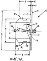
фиг. 1A - вид в разрезе устройства окклюзии в соответствии с одним вариантом осуществления настоящего изобретения;FIG. 1A is a cross-sectional view of an occlusion device in accordance with one embodiment of the present invention;
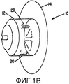
фиг. 1B - вид в перспективе устройства, показанного на фиг. 1A;FIG. 1B is a perspective view of the device shown in FIG. 1A;
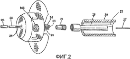
фиг. 2 - частичное изображение в перспективе с пространственным разделением деталей узла альтернативного однодискового устройства и устройства подачи в соответствии с одним вариантом осуществления настоящего изобретения;FIG. 2 is a partially exploded perspective view of an assembly of an alternative single-disk device and a feeder in accordance with one embodiment of the present invention;
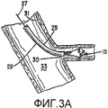
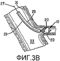
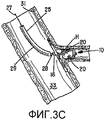
фиг. 3А-3C - последовательные этапы развертывания устройства, показанного на фиг. 1A и 1B;FIG. 3A-3C are successive deployment steps of the device shown in FIG. 1A and 1B;
фиг. 4 - вид в перспективе устройства окклюзии для окклюзии LAA в соответствии с одним вариантом осуществления настоящего изобретения;FIG. 4 is a perspective view of an occlusion device for occlusion of an LAA in accordance with one embodiment of the present invention;
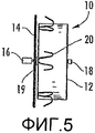
фиг. 5 - вид сбоку устройства окклюзии, показанного на фиг. 4;FIG. 5 is a side view of the occlusion device shown in FIG. four;
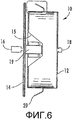
фиг. 6 - вид в разрезе устройства окклюзии, показанного на фиг. 4;FIG. 6 is a sectional view of the occlusion device shown in FIG. four;
фиг. 7 - увеличенный частичный вид сбоку устройства окклюзии, показанного на фиг. 4, показывающий крючок;FIG. 7 is an enlarged partial side view of the occlusion device shown in FIG. 4 showing a hook;
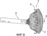
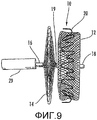
фиг. 8 и 9 - виды в перспективе устройства окклюзии, развертывающегося в соответствии с одним вариантом осуществления настоящего изобретения;FIG. 8 and 9 are perspective views of an occlusion device deployed in accordance with one embodiment of the present invention;
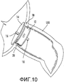
фиг. 10 - вид в перспективе устройства окклюзии, развернутого в LAA в соответствии с вариантом осуществления настоящего изобретения; иFIG. 10 is a perspective view of an occlusion device deployed in an LAA in accordance with an embodiment of the present invention; and
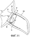
фиг. 11 - вид в перспективе устройства окклюзии, развернутого в LAA в соответствии с другим вариантом осуществления настоящего изобретения.FIG. 11 is a perspective view of an occlusion device deployed in an LAA in accordance with another embodiment of the present invention.
ПОДРОБНОЕ ОПИСАНИЕ ПРЕДПОЧТИТЕЛЬНЫХ ВАРИАНТОВ ОСУЩЕСТВЛЕНИЯDETAILED DESCRIPTION OF THE PREFERRED EMBODIMENTS
Настоящее изобретение в дальнейшем будет теперь описано более полно со ссылкой на сопроводительные чертежи, на которых показаны некоторые, но не все варианты осуществления изобретения. Действительно, настоящее изобретение может быть осуществлено во многих различных формах и не должно рассматриваться как ограниченное изложенными здесь вариантами осуществления; эти варианты осуществления обеспечиваются скорее для того, чтобы это раскрытие удовлетворяло действующим юридическим требованиям. Во всем описании схожие номера относятся к схожим элементам.The present invention will now be described more fully with reference to the accompanying drawings, in which some, but not all embodiments of the invention are shown. Indeed, the present invention can be implemented in many different forms and should not be construed as limited to the embodiments set forth herein; these embodiments are more likely to be provided so that this disclosure meets current legal requirements. Throughout the description, like numbers refer to like elements.
Варианты осуществления настоящего изобретения могут обеспечить улучшенное устройство 10 внутрисосудистой окклюзии, направляемое через чрескожный катетер для использования в сосудистой сети в теле пациентов, как, например, в кровеносных сосудах, каналах, просветах, отверстиях в ткани, полости и т.п. В теле могут возникать и другие физиологические состояния, когда также желательно произвести окклюзию сосуда или другого прохода, чтобы предотвратить кровоток в нем или через него. Эти варианты осуществления устройства могут использоваться в любом месте в сосудистой сети, где анатомические условия соответствуют конструкции.Embodiments of the present invention can provide an improved
В соответствии с одним вариантом осуществления настоящего изобретения для формирования медицинского устройства 10, соответствующего изобретению, металлическая ткань формируется из множества проволочных нитей, имеющих заранее определенную взаимную ориентацию относительно друг друга. Однако само собой разумеется, что в соответствии с дополнительными вариантами осуществления настоящего изобретения устройство 10 может быть сформировано, используя различные методы. Например, устройство 10 могло быть вытравлено или отрезано лазером от трубы так, чтобы сформировать геометрию промежутка, или устройство может содержать материал для окклюзии, присоединенный к конструкции типа строительных лесов или множества срезов трубчатого элемента, соединенных вместе, например, путем склеивания. Кроме того, подразумевается, что устройство 10 может содержать один или более слоев окклюзионного материала, так что устройство может содержать различные окклюзионные материалы, способные, по меньшей мере, частично останавливать кровоток через него, чтобы облегчать формирование тромба.In accordance with one embodiment of the present invention, to form a
Хотя здесь употребляется термин "прядь", "прядь" не предполагает ограничения, поскольку, само собой разумеется, что ткань может содержать одну или более проволочных нитей, оплеток, волокон, пряжи, ниток, корда или им подобного, так что такие термины могут использоваться, взаимно заменяя друг друга.Although the term “strand” is used here, “strand” is not intended to be limiting, since it goes without saying that the fabric may contain one or more wire threads, braids, fibers, yarn, threads, cord or the like, so such terms may be used mutually replacing each other.
Согласно одному варианту осуществления, окклюзионный материал является металлической тканью, содержащей множество жгутов, таких как два набора, по существу, параллельных, в целом, спиральных жгутов, со жгутами одного набора, имеющими "захват", то есть направление вращения, противоположное направлению вращения другого набора. Жгуты могут сплетаться, перемешиваться или как-либо иначе комбинироваться, чтобы определять, в целом, трубчатую структуру.According to one embodiment, the occlusal material is a metal fabric containing a plurality of bundles, such as two sets of substantially parallel, generally parallel spiral bundles, with bundles of one set having a “grip”, that is, a direction of rotation opposite to that of another recruitment. The tows can be woven, mixed, or otherwise combined to define a generally tubular structure.
Шаг жгутов (то есть угол, определяемый между витками жгутов и осью оплетки) и уток ткани (то есть число пересечений нитяных жгутов на единицу длины) могут регулироваться по желанию для конкретного применения. Жгуты металлической ткани из проволочных нитей, используемые в одном варианте осуществления настоящего способа, могут быть изготовлены из материала, который является как эластичным, так и пригодным для термообработки, чтобы, по существу, принять желаемую форму. Материалами, пригодными для этой цели, являются сплав на основе кобальта с малым коэффициентом теплового расширения, упоминаемый в данной области техники как "эльджилой", высокотемпературные высокопрочные "суперсплавы" на основе никеля, коммерчески предлагаемые компанией Haynes International под торговым названием "хастелой", пригодные для термообработки сплавы на основе никеля, продаваемые под названием "инколой" компанией International Nickel, и множество различных марок нержавеющей стали. Важным фактором при выборе соответствующего материала для жгутов из проволочных нитей является то, что нити в достаточной степени сохраняют деформацию, созданную формующей поверхностью (как описано ниже), когда подвергаются заранее определенной термической обработке, и силой упругости возвращаются к упомянутой сформованной форме после существенной деформации.The pitch of the bundles (i.e. the angle defined between the turns of the bundles and the axis of the braid) and the weft of the fabric (i.e. the number of intersections of the strands per unit length) can be adjusted as desired for a particular application. The strands of metal fabric from wire threads used in one embodiment of the present method can be made of a material that is both flexible and suitable for heat treatment to essentially take the desired shape. Suitable materials for this purpose are a low thermal expansion cobalt-based alloy referred to in the art as “elgil”, high-temperature high-strength nickel-based “super alloys” commercially available from Haynes International under the trade name “hastelloy”, suitable for heat treatment, nickel-based alloys sold under the name "Incoloy" by International Nickel, and many different grades of stainless steel. An important factor in choosing the appropriate material for wire harnesses is that the yarns sufficiently retain the deformation created by the forming surface (as described below) when they are subjected to a predetermined heat treatment, and return to said molded shape after substantial deformation by elastic force.
Одним из классов материалов, который удовлетворяет этим квалификационным требованиям, являются так называемые сплавы с памятью формы. Одним конкретно предпочтительным сплавом с памятью формы для использования в настоящем способе является нитинол. NiTi-сплавы также являются очень упругими - их называют "суперупругими" или "псевдоупругими". Эта упругость может позволять устройству возвращаться к заранее установленной раскрытой конфигурации для развертывания после прохождения в деформированной форме через катетер подачи. Кроме того, к другим подходящим материалам относятся те, которые совместимы с отображением магнитного резонанса (MRI), поскольку некоторые материалы в результате выполнения MRI могут вызывать выделение теплоты или появление вращающего момента, а некоторые материалы могут искажать MRI-изображение. Таким образом, могут использоваться металлические и/или неметаллические материалы, которые снижают или исключают те потенциальные проблемы, которые возникают из использования MRI.One of the classes of materials that satisfies these qualification requirements is the so-called shape memory alloys. One specifically preferred shape memory alloy for use in the present process is nitinol. NiTi alloys are also very resilient - they are called "superelastic" or "pseudoelastic". This resilience may allow the device to return to a predetermined open configuration for deployment after passing in deformed form through a delivery catheter. In addition, other suitable materials include those that are compatible with magnetic resonance imaging (MRI), since some materials may cause heat or torque to be generated by performing the MRI, and some materials may distort the MRI image. Thus, metallic and / or non-metallic materials can be used that reduce or eliminate potential problems that arise from the use of MRI.
При изготовлении медицинского устройства в соответствии с одним вариантом осуществления настоящего изобретения, кусок ткани соответствующего размера отрезается от большого куска ткани, которая изготовлена, например, посредством сплетения жгутов из проволочных нитей, чтобы сформировать длинную трубчатую оплетку. При резании ткани до желаемого размера следует соблюдать осторожность, чтобы гарантировать, что ткань не будет распускаться. Концы желаемой длины можно паять, опаивать, сваривать, покрывать, клеить, зажимать, обвязывать или как-либо иначе скреплять вместе (например, с помощью биологически совместимого цементирующего органического материала).In the manufacture of a medical device in accordance with one embodiment of the present invention, a piece of tissue of an appropriate size is cut from a large piece of fabric, which is made, for example, by braiding wire harnesses to form a long tubular braid. When cutting fabric to the desired size, care must be taken to ensure that the fabric does not open. The ends of the desired length can be soldered, soldered, welded, coated, glued, clamped, tied, or otherwise fastened together (for example, using a biocompatible cementitious organic material).
Дополнительно, для изготовления медицинского устройства могут использоваться один или более слоев ткани. Например, два слоя металлической ткани могут раздельно сплетаться в трубчатые элементы, причем один трубчатый элемент располагается коаксиально внутри второго трубчатого элемента. Для дальнейшего обсуждения в отношении многослойного плетеного устройства и способов изготовления такого устройства смотрите публикацию патентной заявки США № 2007/0168019 Amplatz et al., которая настоящим внесена в настоящую заявку во всей ее полноте посредством ссылки.Additionally, one or more layers of tissue may be used to make the medical device. For example, two layers of metal fabric can be separately woven into tubular elements, with one tubular element being coaxially located inside the second tubular element. For further discussion regarding a multilayer wicker device and methods for manufacturing such a device, see US Patent Application Publication No. 2007/0168019 to Amplatz et al., Which is hereby incorporated by reference in its entirety.
Трубчатая оплетка, используемая для изготовления устройства для окклюзии в соответствии с одним вариантом осуществления настоящего изобретения, может иметь диапазон диаметра проволочных нитей от 0,0015 до 0,005 дюйма, предпочтительно, диапазон от 0,003 до 0,0045 дюйма. Количество проволочных нитей в трубчатой оплетке может изменяться от 36 до 144, но предпочтительно находится в диапазоне от 72 до 144. Число уточин оплетки может изменяться от 30 до 100. Ткань имеет среднюю площадь между поддерживающими волокнами 0,0016 см2 и 0,25 см2.The tubular braid used to make the occlusion device in accordance with one embodiment of the present invention may have a wire filament diameter range of 0.0015 to 0.005 inches, preferably a range of 0.003 to 0.0045 inches. The number of wire strands in the tubular braid can vary from 36 to 144, but is preferably in the range from 72 to 144. The number of braid weft can vary from 30 to 100. The fabric has an average area between the supporting fibers of 0.0016 cm 2 and 0.25 cm 2 .
Когда кусок металлической ткани соответствующего размера получен, ткань деформируется, чтобы в целом соответствовать поверхности формующего элемента. Деформация ткани будет переориентировать относительные положения нитяных жгутов металлической ткани с их первоначального порядка во вторую, переориентированную конфигурацию. Форма формующего элемента должна быть выбрана так, чтобы деформировать ткань, по существу, в форму желательного раскрытого медицинского устройства, когда оно не ограничивается в размерах. Когда формующий элемент находится в сборе с металлической тканью, в целом соответствуя формующей поверхности этого элемента, ткань может быть подвергнута термической обработке, пока она остается в контакте с этой формующей поверхностью. После термической обработки контакт ткани с формующим элементом прекращается и она, по существу, будет сохранять его форму, находясь в деформированном состоянии.When a piece of metal fabric of an appropriate size is obtained, the fabric is deformed to generally correspond to the surface of the forming element. The deformation of the fabric will reorient the relative positions of the strands of metal fabric from their original order to a second, reoriented configuration. The shape of the forming element should be selected so as to deform the fabric substantially into the shape of the desired disclosed medical device when it is not limited in size. When the forming element is assembled with a metal fabric, generally corresponding to the forming surface of this element, the fabric can be subjected to heat treatment while it remains in contact with this forming surface. After heat treatment, the contact of the fabric with the forming element is terminated and it will essentially retain its shape while in a deformed state.
На фиг. 1A и 1B показан вариант осуществления медицинского устройства 10, соответствующего одному варианту осуществления настоящего изобретения. Устройство 10 имеет часть 12 обычно цилиндрического корпуса и снаружи выдвинутое вперед дисковое окончание 14. Часть 12 корпуса имеет размер, который должен быть несколько больше (например, приблизительно на 10-30%), чем сосуд, подлежащий окклюзии. Этот размер должен быть таким, чтобы обеспечивать элемент анкерного крепления устройства для предотвращения перемещения. Дисковая часть 14 устройства 10 предназначена для примыкания к смежной стенке, окружающей отверстие, чтобы предотвратить перемещение устройства в направлении части корпуса и помочь герметизировать отверстие. В соответствии с одним вариантом осуществления, дисковая часть 14 имеет увеличенный размер, чтобы иметь возможность перекрывать устье или отверстие LAA и накладываться и обеспечивать контакт по всей плоскости со стенкой предсердия, как показано на фиг. 10 и 11. Дисковая часть 14 может также быть гибкой, чтобы иметь возможность следовать за кривизной стенки полости. Дисковая часть 14 может иметь различные размеры и конфигурации типа плоского диска, как показано на фиг. 1A, 1B, 4 и 10, или диска, имеющего выпуклый дистальный конец, как показано на фиг. 11. Дисковая часть 14 может иметь высоту или толщину, зависящую от толщины и количества используемых слоев, хотя высота должна быть минимизирована благодаря возможности образования сгустка вокруг дисковой части и уменьшенного объема внутри полости.In FIG. 1A and 1B show an embodiment of a
Часть 12 корпуса может иметь увеличенный размер, чтобы она входила в зацепление с просветом сосуда, органа тела или тому подобным, что должно быть перекрыто. Устройство 10 в этом случае может удерживаться на месте комбинацией радиального зацепления между частью корпуса и просветом сосуда, органом тела или тому подобным и крючками 20, которые зацепляются за стенку. Через относительно короткий период времени внутри и на устройстве 10 формируются тромбы и перекрывают просвет. Хотя часть 12 корпуса и дисковая часть 14 могут иметь разные размеры, в соответствии с одним вариантом осуществления дисковая часть может иметь, по меньшей мере, приблизительно на 10% больший диаметр, чем часть корпуса.
Например, на фиг. 10 показано устройство 10 для окклюзии, имплантированное внутрь LAA. Устройство 10 для окклюзии расположено так, что дисковая часть 14 накрывает вход в LAA в то время, когда часть 12 корпуса располагается внутри LAA. Таким образом, дисковая часть 14 обеспечивает имплантацию части 12 корпуса на заранее определенную глубину внутрь LAA. Часть 12 корпуса имеет размеры и выполнен с возможностью саморасширения и зацепления за стенку LAA, а крючки 20 выполнены с возможностью проникновения в стенку LAA, как объясняется ниже. Со временем внутри и на дисковой части 14 и части 12 корпуса формируется тромб, чтобы произвести окклюзию LAA.For example, in FIG. 10 shows an
Специалисты в данной области техники должны понимать, что для ускорения окклюзии устройством для сосуда устройство может быть покрыто соответствующим тромбообразующим средством, наполнено полиэфирным волокном, сплетено с увеличенным количеством жгутов из проволочных нитей или содержать множество слоев ткани. Например, устройство 10 может содержать один или более слоев полиэфирного волокна, помещенного внутрь части 12 корпуса и/или дисковой части 14. В частности, слой полиэфирного волокна может иметь размеры и быть выполнен с возможностью размещения внутри каждой части 12 корпуса и дисковой части 14 и присоединения по окружности по их периферии и по внутренней окружности части корпуса и дисковой части соответственно. Полиэфирное волокно является гибким и может легко сжиматься устройством 10 для подачи через катетер. Переплетенное волокно может прикрепляться к сгустку, чтобы надежно удерживать сгусток внутри устройства, пока оно формирует окклюзию.Specialists in the art should understand that to accelerate the occlusion of the device for the vessel, the device can be covered with an appropriate thrombogenic agent, filled with polyester fiber, woven with an increased number of wire strands or contain many layers of fabric. For example, the
Следовательно, устройство 10 может содержать множество плоскостей окклюзии. Плоскостью окклюзии может быть любая поверхность, плоская или неправильной формы, которую можно ориентировать в целом поперек кровотока, чтобы облегчить формирование тромба. Например, часть 12 корпуса и дисковая часть 14 могут содержать, по меньшей мере, одну плоскость окклюзии, такую как каждая поверхность или слой дисковой части и каждая поверхность или слой части корпуса. Кроме того, дополнительные слои ткани и/или каждый слой полиэфирного волокна внутри дисковой части и/или части корпуса могут добавлять дополнительные плоскости окклюзии. Дополнительно, одна или более плоскостей окклюзии, связанных с дисковой частью 14, могут располагаться так, чтобы накладываться на вход в LAA, в то время, как одна или более плоскостей окклюзии, связанных с частью 12 корпуса, могут размещаться внутри полости, определяемой LAA. Согласно одному варианту осуществления настоящего изобретения, первая часть и вторая часть устройства 10 выполнены с возможностью окклюзии, по меньшей мере, части LAA приблизительно менее чем за 10 минут, и даже меньше, чем за 5 минут, с наблюдавшимися при испытании окклюзией, происходившими менее чем за 1 минуту.Therefore, the
Устройство 10 содержит переходный сегмент 19 диаметром H между частью 12 корпуса и дисковой частью 14, диаметр которого существенно меньше, чем диаметр B цилиндра и диаметр А диска. Малый диаметр переходного сегмента позволяет дисковой части легко ориентироваться на стене сосуда, содержащей отверстие, когда стенка не точно перпендикулярна. В соответствии с одним вариантом осуществления, часть 12 корпуса способна изгибаться под углом М приблизительно до 30° относительно переходного сегмента 19, как показано на фиг. 1A. Дополнительно, диаметр H переходного сегмента, утопленного внутрь углубления 15 на конце элемента 12 корпуса, может позволить устройству соответствовать анатомии, в которую устройство помещается, действуя подобно пружинному элементу для поддержания осевого натяжения между диском и цилиндрическим корпусом. Промежуток между диском и цилиндрическим корпусом не может повлиять на характеристики устройства.The
Как показано на фиг. 1A, 1B и 7, устройство 10 может содержать удерживающие крючки 20. Удерживающие крючки 20 могут изготавливаться из нитиноловой нити, которой с помощью термообработки на каждом конце придана форма крючка и которая имеет изгиб, например изгиб меньше, чем приблизительно 180°, в середине сегмента длины нити, чтобы создать 2 взаимосвязанных крючка. Крючки 20 могут также проходить внутрь устройства 10, как показано на фиг. 7. Концы крючков ориентируются в направлении диска и могут присоединяться или прикрепляться любым известным способом к плетеной ткани на части 12 корпуса устройства. В соответствии с одним вариантом осуществления, проволоки крючков 20 могут иметь диаметр приблизительно 0,003-0,007 дюйма и длину 2-10 мм и быть достаточно гибкими, чтобы загибаться назад при загрузке в катетер подачи или вперед при загрузке, когда вводятся в выпрямленной конфигурации. Устройство может иметь любое количество крючков 20, такое как, например, три пары крючков. Количество крючков предпочтительно должно быть в диапазоне от 6 до 12. Крючки помогают удерживать устройство с помощью противодействия движению устройства в сосуде в направлении, которое может вызывать зацепление крючков за ткань. Крючки 20 не имеют зубцов, поэтому их выход из зацепления возможен за счет перемещения устройства в направлении, противоположном открытому концу крючка. Кроме того, крючки 20 могут быть выполнены с возможностью прокалывания стенки LAA, но без проникновения полностью через стенку LAA. Таким образом, крючки 20 снижают степень истечения за счет того, что не прокалывают стенку LAA.As shown in FIG. 1A, 1B and 7, the
В одном варианте осуществления, крючки 20 могут быть частью устройства, то есть отдельные проволоки внутри сплетенной структуры, которые изолированы, обрезаются и короткая часть проволоки, соседствующая с местом обрезания, формуется в выступающую наружу проволоку или крючок. Преимущество этой конфигурации состоит в том, что устройство имеет значительно более низкий профиль, так как никакой добавочный материал (отдельные крючки) не вносится в сжатую конфигурацию во время прохождения через катетер. Кроме того, нет никакого добавочного материала скрепляющего шва или узлов шва, необходимых для крепления крючков к плетеной ткани, снижая таким образом также профиль стента.In one embodiment, the
Как объяснялось выше, часть 12 корпуса цилиндрической формы выполнена с возможностью развертывания внутри сосуда, полости или тому подобного, подлежащего окклюзии, тогда как дисковая часть 14 выполнена с возможностью расположения рядом со стенкой, окружающей отверстие, связанное с сосудом, полостью или чем-либо подобным, подлежащим окклюзии. В соответствии с одним вариантом осуществления, устройство 10 имеет длину от проксимального зажима 16 дискового окончания по радиусу наружу до максимального диаметра А диска и обратно по радиусу внутрь себя до переходного диаметра H. Переходной диаметр H имеет длину J в дистальном направлении, за счет чего устройство 10 формирует обратный конус в направлении диска 14 с диаметром K, когда устройство поворачивается, чтобы следовать параллельно диску, но отделенным от диска на расстояние E, в направлении наружу по радиусу до диаметра B. Устройство 10 продолжает сохранять цилиндрический диаметр B в дистальном направлении на расстояние D. Устройство 10 может содержать коническую поверхность под углом C, как показано на фиг. 1A, или не содержать коническую поверхность, как показано на фиг. 4-6, и определять часть 12 корпуса как имеющую общую длину G. В соответствии с одним вариантом осуществления, зажим 18 на дистальном конце и зажим 16 на проксимальном конце удерживают сплетенные концы проволок от расплетения. Однако, само собой разумеется, что устройство 10 может содержать концевой зажим на своем проксимальном и/или дистальном конце. Например, устройство 10 может содержать зажим 16 на проксимальном конце, в то время, как дистальный конец устройства зажима не имеет. Кроме того, само собой разумеется, что концы устройства 10 могут соединяться, используя различные методы, отличные от зажимов, такие как сварка, сцепление, связывание, крепежные элементы или тому подобное. Зажим 16 на проксимальном конце также содержит резьбовую часть, которая реверсивно соединяется с системой подачи (не показана), такой как трос или стержень с соединительной резьбой на его конце. Зажим 16 на проксимальном конце и/или зажим 18 на дистальном конце могут быть из рентгеноконтрастного материала типа платинового маркера для помощи хирургу в регулировке положения устройства 10 внутри сосуда или органа тела.As explained above, the
Повышение гибкости диска и соответствия стенке сосуда, органу тела или тому подобному, не перпендикулярным оси сосуда, органу тела или тому подобному, подлежащему окклюзии, происходит за счет соотношения максимального диаметра А диска и малого диаметра H или отношения A/H. В соответствии с одним вариантом осуществления, отношение находится в диапазоне от 3 до 30 и предпочтительно приблизительно от 10 до 25, а отношение B/H находится в диапазоне 2-25 и предпочтительно равно 10-20. Это отношение может снижать силу изгиба, необходимую для выравнивания диска относительно стенки сосуда, органа тела или тому подобного или, альтернативно, для выравнивания части тела относительно сосуда, органа тела или тому подобного, подлежащего окклюзии. Переходной диаметр H имеет длину J, которая составляет приблизительно 2-5 диаметров H. Эта длина J может быть необходима, чтобы позволить иметь небольшое расстояние E между внутренней поверхностью диска и стенкой проксимального конца части корпуса, как показано на фиг. 1A. Это может улучшать посадку устройства и герметизацию устройства. Чтобы вместить длину J с переходным диаметром H, устройство имеет такую форму, чтобы формировать коническую поверхность под углом L к стенке ближнего конца части корпуса. Эта коническая поверхность может давать место для перемещения пользователем части корпуса от расположения рядом с диском до спрямления конуса и таким образом обеспечивает повышенную силу расширения в радиальном направлении для удержания устройства на проксимальном внешнем диаметре цилиндра. Дополнительно, коническая поверхность может действовать как пружина, чтобы обеспечивать осевое растяжение между диском и частью корпуса, когда они перемещаются в стороны, чтобы сохранять крючки 20 сцепленными со стенкой сосуда, подлежащего окклюзии, тем самым улучшая удержание устройства. Кроме того, цилиндрическая часть может быть преднамеренно помещена на определенном расстоянии от дисковой части, что наблюдается с помощью ангиографии, чтобы гарантировать силу удержания между дисковой и цилиндрической частью. Расстояние позволяет иметь большую гибкость при размещении цилиндрической части и способность адаптации к широкому диапазону анатомических состояний.Increasing the flexibility of the disk and matching the vessel wall, body organ or the like, not perpendicular to the axis of the vessel, body organ or the like, to be occluded, is due to the ratio of the maximum diameter A of the disk and small diameter H or the ratio A / H. In accordance with one embodiment, the ratio is in the range of 3 to 30 and preferably about 10 to 25, and the B / H ratio is in the range of 2-25 and preferably 10-20. This ratio may reduce the bending force necessary to align the disk relative to the wall of the vessel, body organ, or the like, or, alternatively, to align part of the body with the vessel, body organ, or the like to be occluded. The transition diameter H has a length J, which is about 2-5 diameters H. This length J may be necessary to allow a small distance E between the inner surface of the disk and the wall of the proximal end of the housing part, as shown in FIG. 1A. This can improve the fit of the device and the sealing of the device. To accommodate a length J with a transition diameter H, the device is shaped to form a conical surface at an angle L to the wall of the proximal end of the housing part. This conical surface can provide a place for the user to move part of the housing from the location near the disk to the straightening of the cone and thus provides increased expansion force in the radial direction to hold the device at the proximal outer diameter of the cylinder. Additionally, the conical surface can act as a spring to provide axial tension between the disk and part of the housing when they move to the sides to keep the
В соответствии с одним вариантом осуществления, разница в длине между размерами B и K и между размерами D и J может поддерживаться постоянной для множества размеров устройств 10, хотя для разных размеров устройств размеры L и K могут изменяться. В соответствии с другим аспектом настоящего изобретения, глубина устройства (то есть G+E) может оставаться постоянной для разных размеров устройств 10. Например, диаметры B и А могут изменяться, тогда как глубина G+E остается одной и той же для обоих устройств. Один аспект настоящего изобретения, связанный с устройством для окклюзии LAA, имеет высоту G+E меньше 10 мм.According to one embodiment, the difference in length between sizes B and K and between sizes D and J can be kept constant for a plurality of sizes of
Размеры корпуса 12 и диска 14 и длина устройства могут изменяться по желанию для различных размеров сосудов, каналов, просветов, отверстий, полостей или тому подобного. В приведенной ниже таблице примеров диапазонов размеров для выбора устройств размеры приводятся в миллиметрах (мм). Примеры размеров, приведенные ниже, даются для устройства 10 в его раскрытом исходном положении, поскольку размеры могут изменяться, когда развертывание происходит внутри тела (например, длина устройства может измениться, если элемент 12 корпуса изогнется относительно дисковой части 14).The dimensions of the
Со ссылкой на Таблицу устройство 10 с диаметром A, равным 20 мм, в одном варианте осуществления изготавливается из 144 прядей проволочных нитей из нитинола диаметром 0,003 дюйма, свитых на 18-миллиметровом шпинделе с числом утков 40. После термоусадки 20-миллиметрового устройства 10 в его окончательно сформованной форме имеющего крючки, сформированные непосредственно из оплетки, устройство может быть сжато для подачи сквозь катетер 29 подачи с внутренним диаметром 7 по шкале Шаррьера и наружным диаметром 9 по шкале Шаррьера (размер 3 по шкале Шаррьера соответствует 1 мм).With reference to the Table, a
С дальнейшей ссылкой на Таблицу устройство 10 с диаметром А, равным 34 мм, в одном варианте осуществления изготовлено из 144 прядей из проволочных нитей из нитинола диаметром 0,0045 дюйма, сплетенных на шпинделе диаметром 30 мм с числом утков 25. После термоусадки 34-миллиметрового устройства 10 в его окончательно сформованной форме имеющего крючки, сформированные непосредственно из оплетки, устройство может быть сжато для подачи сквозь катетер 29 подачи с внутренним диаметром 9 по шкале Шаррьера и наружным диаметром 11 по шкале Шаррьера.With further reference to the Table,
Система подачи 28, показанная на фиг. 2, может использоваться для принудительного пропускания устройства 10 через просвет катетера или длинную оболочку интродуктора для развертывания в теле пациента. Система подачи 28 может принимать любую подходящую форму, такую как удлиненный гибкий металлический стержень, подобный обычному проволочному направителю, или может быть пустотелым стержнем. Система подачи 28 используется для продвижения вперед устройства 10 для окклюзии через просвет 25 цилиндрической трубки малого диаметра, такой как катетер 29 подачи, для развертывания. The
В соответствии с одним вариантом осуществления, устройство 10 загружается в просвет 25 посредством его растягивания, чтобы вставить его в удлиненном состоянии. Устройство 10 может быть вставлено в просвет 25 во время процедуры или быть заранее собрано на производственном средстве, в котором устройства, соответствующие настоящему изобретению, не принимают остаточную деформацию, когда поддерживаются в сжатом состоянии. Когда устройство развертывается из дистального конца катетера, устройство будет все еще удерживаться системой подачи. Когда соответствующее положение устройства 10 в сосуде, органе тела или в подобном месте подтверждается, стержень системы подачи 28 может поворачиваться вокруг своей оси, чтобы отвинтить зажим 16 с резьбового конца системы подачи. Конечно, резьбовое соединение может быть на любом конце устройства в зависимости от анатомической ситуации и желательного или имеющегося в наличии средства доступа к месту лечения.In accordance with one embodiment, the
Сохраняя соединение устройства 10 с системой подачи, оператор все еще может вытянуть устройство обратно в оболочку подачи для повторной регулировки положения, если определено, что устройство с первой попытки не установлено должным образом. В тех случаях, когда устройство 10 не развернулось надлежащим образом с первой попытки, устройство может быть извлечено, вытягивая систему 28 подачи в проксимальном направлении, таким образом втягивая устройство назад в катетер 29 подачи перед второй попыткой регулировки положения устройства относительно сосуда, органа тела или тому подобного. Резьбовое крепление может также позволить оператору управлять образом, которым устройство 10 развертывается из дистального конца катетера подачи. Как объясняется ниже, когда устройство выходит из катетера подачи, оно будет иметь тенденцию за счет силы упругости возвращаться в раскрытую форму, которая была установлена, когда ткань прошла термообработку. Когда устройство силой упругости возвращается в эту форму, оно может иметь тенденцию воздействовать на дистальный конца катетера, эффективно продвигая себя вперед из конца катетера. Это пружинящее действие, очевидно, может привести в результате к неправильному расположению устройства. Поскольку резьбовой зажим 16 может позволить оператору сохранять связь с устройством во время развертывания, пружинящее действие устройства может контролироваться и оператор может управлять развертыванием, чтобы гарантировать правильное расположение.While maintaining the connection of the
Как вариант, устройство 10 может быть выполнено с возможностью использования полого элемента 23 внутреннего зажима на обоих концах проволочной нити и проксимального элемента 21 внешнего зажима и дистального элемента 26 внешнего зажима. Концы 24 проволочной нити изгибаются между элементами 21, 26 внутреннего и внешнего зажимов посредством обжимки или, альтернативно, могут быть прикреплены или приварены между элементами зажимов. Внутренний элемент зажима является трубчатым и имеет такой размер внутреннего диаметра, который позволяет ему свободно пропускать проволочный толкатель 27. Дистальный элемент 26 внешнего зажима имеет внутренний диаметр, достаточный для размещения концов 24 проволочных нитей оплетки, окружающих элемент внутреннего зажима перед обжимкой. Дистальный конец на дистальном элементе 26 внешнего зажима является жестким (закрытый конец), чтобы принимать силу нажатия от проволочного толкателя 27, проходящего сквозь оба элемента внутреннего зажима, на этот жесткий конец. Проксимальный элемент 21 внешнего зажима показан с наружными резьбами, чтобы реверсивно соединяться с системой 28 подачи, который может быть внутренней трубкой, экструдированной из блоксополимера нейлона, такого как Pebax, оплетенной проволочной нитью диаметром 0,001 дюйма поверх экструдированной внутренней трубки из Pebax с последующим покрытием оплетки другим наружным слоем из Pebax. Катетер/оболочка 29 для подачи может быть сконструирован аналогично, за исключением того, что он должен иметь больший диаметр, чтобы обеспечивать прохождение устройства 10 и системы подачи 28. Такая конструкция является типичной для внутрисосудистых катетеров, где необходимы гибкость и передача вращающего момента. Подобно указанным выше зажимам 16, 18 внутренний 23 и/или внешний 26 элемент зажима может быть выполнен из рентгеноконтрастного материала, такого как платиновый маркер, для оказания помощи хирургу при регулировке положения устройства 10 в просвете. Alternatively,
В соответствии с одним вариантом осуществления, оболочка 29 катетера подачи может иметь внутренний слой из тефлона (PTFE) толщиной 0,001 дюйма, чтобы снизить трение для простоты прохождения устройства через него. Полая система подачи имеет размеры, позволяющие проволочному толкателю 27, выполненному из нержавеющей стали диаметром 0,008-0,014 дюйма, проходить через систему подачи и проксимальный зажим и входить в зацепление с дистальным зажимом, чтобы выталкивать дистальный зажим из проксимального зажима, удлинить устройство, облегчить отцепление крючков и облегчить возвращение устройства в оболочку 29 подачи. Дистальный конец проволочного толкателя 27 и дистальный внутренний зажим 23 могут быть сконструированы для скрепления резьбовым соединением или другим реверсивным средством, чтобы гарантировать, что проволока по неосторожности не окажется установленной проксимально относительно дистального внутреннего зажима 23. Посредством системы 28 подачи, поддерживающей контроль за проксимальным концом устройства 10 и проволочным толкателем 27, способным прикладывать толкающую силу к дистальному концу устройства, устройство может удлиняться или позволять самораскрываться и сокращаться по длине по мере необходимости. Это помогает производить повторную регулировку положения, когда крючки легко освобождаются нажатием на проволочный толкатель, чтобы протолкнуть устройство в дистальном направлении. Это также помогает вытаскивать устройство обратно в оболочку 29, если в этом возникает необходимость, например, когда размер устройства не соответствует анатомии тела. Хотя проволочный толкатель 27 описывается как предназначенный для толкания на дистальном конце устройства, проволочный толкатель может использоваться как проволочный направитель катетера в соответствии с одним вариантом осуществления. Таким образом, проволочный толкатель 27 может быть выполнен с возможностью удлинения в дистальном направлении дистальных элементов внутреннего 23 и внешнего 26 зажимов так, что устройство 10 может подаваться по проволоке, как подробно объясняется ниже. В этом варианте осуществления, дистальный элемент 26 зажима является трубчатым с открытыми концами и имеет проход через него, достаточный для прохождения проволочного направителя 27.In accordance with one embodiment, the
На фиг. 3A-C схематично показано, как медицинское устройство 10, обычно такое, как в общих чертах описано выше, может использоваться для окклюзии сосуда, канала, просвета, отверстия, полости или тому подобного, подлежащего окклюзии. Устройство 10 может быть сжато и прикреплено к системе 28 подачи так, что сжатое устройство может быть пропущено через катетер 29 подачи и дистальный конец катетера подачи будет находиться рядом с отверстием 30 в стенке 31 сосуда, как показано на фиг. 3A. Система 28 подачи продвигается вперед в дистальном направлении, упираясь в катетер 29 подачи 29, чтобы заставить дистальный конец устройства 10 выйти из катетера 29 и за счет силы упругости саморазвернуться, по существу, в его заранее определенное термофиксированное при формовке состояние, посредством чего оно входит в контакт со стенкой сосуда. В этот момент дистальный конец катетера 29 может отреагировать на силу расширения и передвинуться в проксимальном направлении на небольшое расстояние, как показано на фиг. 3B. Крючки 20 начинают входить в контакт со стенкой сосуда, чтобы удерживать устройство на месте. Если необходима установка положения в дистальном направлении, это может быть сделано, поскольку в этом направлении крючки будут освобождаться. На фиг. 3C устройство полностью выходит от катетера 29, но все еще прикреплено к системе подачи 28. Как показано на этом чертеже, диск 14 самовыравнивается относительно стенки 31, поворачиваясь вокруг малого диаметра H. После того как устройство установилось на желаемое место, система подачи отсоединяется путем вращения системы 28 подачи в направлении разъединения резьбового соединения на проксимальном концевом зажиме 16.In FIG. 3A-C schematically illustrates how a
В целом, способ, соответствующий одному варианту осуществления настоящего изобретения, содержит способ лечения физиологического состояния пациента. В соответствии с этим способом, выбирается медицинское устройство, пригодное для лечения состояния, которое может, по существу, соответствовать одному из вариантов осуществления, подробно описанным выше. Например, если необходима окклюзия LAA, может использоваться устройство 10, показанное на фиг. 1A, 1B и 4. Устройство 10 может подаваться и должным образом размещаться, используя двумерную внутрисердечную эхокардиографию (ICE), отображение магнитного резонанса (MRI), чреспищеводную эхокардиографию, двухпроекционную ангиографию и/или доплеровское цветовое картографирование кровотока. С появлением двумерной ICE, MRI, чреспищеводной эхокардиографии, двухпроекционной ангиографии и доплеровского цветового картографирования кровотока приблизительная анатомия дефекта может быть представлена визуально. Устройство 10, которое должно будет использоваться, должно основываться на приблизительном размере сосуда, полости или тому подобного, подлежащего окклюзии. Когда соответствующее медицинское устройство выбрано, катетер может быть помещен внутри канала в теле пациента, чтобы разместить дистальный конец катетера вблизи желательного места лечения, например, в непосредственной близости или внутри полости LAA.In general, a method according to one embodiment of the present invention comprises a method for treating a physiological condition of a patient. In accordance with this method, a medical device suitable for treating a condition that can essentially correspond to one of the embodiments described in detail above is selected. For example, if LAA occlusion is needed, the
Медицинское устройство 10 может быть сжато в свою сжатую конфигурацию и вставлено в просвет катетера. Сжатая конфигурация устройства может иметь любую форму, пригодную для легкого прохождения сквозь просвет катетера и соответствующего развертывания из дистального конца катетера. Например, устройства, показанные на фиг. 1 A, 1B, 2 и 4-10, имеют относительно удлиненную сжатую конфигурацию, в которой устройства вытянуты вдоль их осей для введения в катетер. Эта сжатая конфигурация может быть достигнута простым растягиванием устройства 10 в целом вдоль его оси, например, захватывая вручную противоположные концы устройства и растягивая их в стороны, что будет создавать тенденцию к сжатию части 12 корпуса и дисковой части 14 устройства 10 внутрь в направлении оси устройства. В этом отношении устройство 10 мало чем отличается от "китайских наручников", которые имеют тенденцию к уменьшению диаметра при растяжении по оси.The
Медицинское устройство 10 может также сжиматься за счет протягивания системы 28 подачи, присоединенной к медицинскому устройству, в проксимальном направлении через трубку интродуктора (не показан), проходящую по длине оси системы подачи. При протягивании через проксимальный конец система 28 подачи тянет устройство 10 в трубку интродуктора с внутренним диаметром, сохраняющим диаметр медицинского устройства таким, чтобы позволить продвигать его вперед, загружая в катетер 29.The
Когда медицинское устройство 10 сжато и вставлено в катетер, оно может проталкиваться вдоль просвета катетера к дистальному концу катетера. Это может быть выполнено, используя систему подачи или что-либо подобное, соединенное с возможностью съема с устройством для проталкивания его по катетеру. Когда устройство начинает выходить из дистального конца катетера, который располагается рядом с желаемым местом лечения, оно будет иметь тенденцию вернуться за счет силы упругости, по существу, полностью в свою ранее установленную развернутую конфигурацию. Сверхупругие сплавы типа нитинола особенно полезны при таком применении из-за их способности легко возвращаться к конкретной конфигурации после значительной степени упругой деформации. Следовательно, простое выталкивание медицинского устройства из дистального конца катетера имеет тенденцию должным образом развертывать устройство в месте лечения.When the
Хотя устройство будет иметь тенденцию возвращаться за счет силы упругости к своей начальной развернутой конфигурации (то есть к своей форме до сжатия перед прохождением через катетер), следует понимать, что оно не может всегда полностью вернуться к этой форме. Например, элемент 12 корпуса, показанный на фиг. 1A, 1B, 2 и 4-11, подразумевается имеющим максимальный внешний диаметр в своей развернутой конфигурации, по меньшей мере, таким же большим, а предпочтительно большим, как внутренний диаметр просвета, в котором он должен быть развернут. Если такое устройство развертывается в сосуде, органе тела или тому подобном, имеющем малый просвет, просвет будет препятствовать полному возвращению устройства в его раскрытую конфигурацию. Тем не менее, устройство должно быть развернуто соответствующим образом, потому что оно должно войти в зацепление с внутренней стенкой просвета, чтобы поместить в него устройство так, как подробно описано выше.Although the device will tend to return due to the elastic force to its initial deployed configuration (that is, to its shape prior to compression before passing through the catheter), it should be understood that it cannot always fully return to this shape. For example, the
Если устройство должно использоваться для постоянной окклюзии канала в теле пациента, устройства типа 10 и 300, описанные выше, могут быть просто отсоединены от системы подачи (пример, показанный на фиг. 6) реверсированием реверсируемого соединения в устройстве и вытягиванием катетера и системы подачи из тела пациента. При этом медицинское устройство остается развернутым в сосудистой системе пациента, так что оно может произвести окклюзию кровеносного сосуда или другого канала в теле пациента.If the device is to be used for permanent channel occlusion in the patient’s body, devices of
В соответствии с одним вариантом осуществления, устройство 10 может быть имплантировано в полость LAA, используя метод направления по проволоке. При чрессосудистой имплантации в LAA врач сначала получает доступ к правому предсердию через бедренную вену с помощью проволочного направителя. Катетер может затем быть введен по проволочному направителю и в правое предсердие. Полый стержень иглы может затем быть введен по проволочному направителю через проволочный направитель и использоваться для прокола перегородки сердца. После формирования отверстия в перегородке проволочный направитель может продвигаться в проксимальном направлении к LAA. Катетер может пройти через отверстие в перегородке с помощью проволочного направителя и двигаться в проксимальном направлении к LAA или войти внутрь LAA. Игла может затем быть удалена, хотя проволочный направитель остается на месте. Проволочный направитель может затем быть удален и катетер подачи, имеющий устройство 10, сжатое в нем, может подаваться в проксимальном направлении в область LAA. В случае устройства 10, имеющего пустотелые зажимы 21, 23, 26 на проксимальном и дистальном концах, предназначенные для пропускания проволочного направителя через них, проволочный направитель может оставаться на месте, в то время как устройство продвигается вперед по проволочному направителю. In accordance with one embodiment,
Дистальный конец катетера 29 может быть частично введен внутрь LAA. Катетер 29 подачи может затем быть вытянут в проксимальном направлении, удерживая при этом неподвижной систему 28 подачи, которая выталкивает элемент 14 корпуса в дистальном направлении из катетера подачи 29, где он силой упругости возвращается в свою ранее определенную развернутую форму. Элемент 12 корпуса раскрывается до диаметра LAA, но обычно только частично проникает вглубь LAA, как показано на фиг. 10. По мере того, как элемент 12 корпуса раскрывается, крючки 20 освобождаются от катетера и зацепляются за LAA, чтобы дополнительно фиксировать в нем устройство 10. После того как система 28 подачи полностью освободится от катетера 29, она может быть продвинута вперед в положение, когда диск надежно располагается на стенке полости, окружающей вход в LAA или отверстие LAA. В соответствии с одним вариантом осуществления, через катетер 29 и в левое предсердие может вводиться рентгеноконтрастное средство, чтобы визуально представлять на ангиограмме, изолировано ли LAA от левого предсердия или связано с ним. Когда слои полиэфирного волокна помещаются внутри части 12 корпуса и дисковой части 14, контрастное средство обычно постоянно присутствует между слоями полиэфирного волокна. Если контрастное средство попадает в LAA, но остается там после заранее определенного периода времени (например, меньше, чем через 10 минут), то связь с левосторонним предсердием незначительна и положение устройства 10 правильное. В противном случае, устройство 10 может нуждаться в повторной установке в нужное положение. Таким образом, устройство 10 может быть способно, по существу, производить окклюзию LAA приблизительно менее чем за 10 минут, так что никакая дальнейшая визуализация или контроль LAA не требуются. Устройство 10 может быть отсоединено путем вращения системы 28 подачи в направлении разъединения резьбового соединения зажима 16 на проксимальном конце. Как показано на фиг. 10, диск 14 самовыравнивается со стенкой LAA, поворачиваясь вокруг переходного сегмента 19 так, чтобы диск покрывал отверстие LAA.The distal end of the
Хотя был описан предпочтительный вариант осуществления настоящего изобретения, следует понимать, что в нем могут быть сделаны различные изменения, переделки и модификации, не отходя от сущности изобретения и объема формулы изобретения, приведенной в конце. Например, допускается, что часть корпуса может быть цилиндрической, бочкообразной, с вогнутой поверхностью, с выпуклой поверхностью, конусообразной или комбинацией форм, не отходя от описанного здесь изобретения. Аналогично, дистальный и проксимальный концы части корпуса могут иметь формы, отличающиеся от описанного конического углубления, сохраняя в то же время описанные выгоды.Although a preferred embodiment of the present invention has been described, it should be understood that various changes, alterations, and modifications can be made therein without departing from the spirit of the invention and the scope of the claims presented at the end. For example, it is assumed that a portion of the housing may be cylindrical, barrel-shaped, with a concave surface, with a convex surface, cone-shaped, or a combination of shapes, without departing from the invention described herein. Likewise, the distal and proximal ends of the body portion may have shapes different from the described conical recess, while maintaining the benefits described.
Специалистами в области техники, к которой относится изобретение, могут быть придуманы многочисленные изменения и другие варианты осуществления изобретения, изложенного здесь, обладающие преимуществами идей, представленных в предшествующих описаниях и на сопутствующих чертежах. Поэтому следует понимать, что изобретение не должно ограничиваться конкретными раскрытыми вариантами осуществления и что изменения и другие варианты осуществления должны подразумеваться содержащимися в объеме приложенной формулы изобретения. Хотя здесь используются специальные термины, они используются только в обобщенном и описательном смысле, но не для целей ограничения.Numerous changes and other embodiments of the invention set forth herein may be devised by those skilled in the art to which the invention pertains, taking advantage of the ideas presented in the foregoing descriptions and the accompanying drawings. Therefore, it should be understood that the invention should not be limited to the particular disclosed embodiments, and that changes and other embodiments should be intended to be included within the scope of the attached claims. Although specific terms are used here, they are used only in a generalized and descriptive sense, and not for purposes of limitation.
Claims (15)
первую часть, имеющую первый диаметр, обеспечивающий перекрытие отверстия левого ушка предсердия, и выполненную с возможностью размещения поперек и снаружи левого ушка предсердия; и
вторую цилиндрическую часть, имеющую второй диаметр, обеспечивающий перекрытие просвета полости, определяемой левым ушком предсердия, и выполненную с возможностью размещения, по меньшей мере, частично внутри и поперек упомянутой полости,
при этом каждая из первой части и второй части содержат, по меньшей мере, одну плоскость окклюзии и соединены переходным сегментом, выполненным с возможностью обеспечения гибкости между первой и второй частями до 30°.1. A medical device for occlusion of the left atrial ear, while the medical device contains
the first part having a first diameter that overlays the opening of the left atrium and is arranged to be placed across and outside the left atrium; and
the second cylindrical part having a second diameter, providing overlap of the lumen of the cavity defined by the left ear of the atrium, and made with the possibility of placement, at least partially inside and across the cavity,
wherein each of the first part and the second part contains at least one occlusion plane and is connected by a transitional segment configured to provide flexibility between the first and second parts up to 30 °.
Applications Claiming Priority (2)
| Application Number | Priority Date | Filing Date | Title |
|---|---|---|---|
| US11/966,397 | 2007-12-28 | ||
| US11/966,397 US20090171386A1 (en) | 2007-12-28 | 2007-12-28 | Percutaneous catheter directed intravascular occlusion devices |
Publications (2)
| Publication Number | Publication Date |
|---|---|
| RU2008151964A RU2008151964A (en) | 2010-07-10 |
| RU2405473C2 true RU2405473C2 (en) | 2010-12-10 |
Family
ID=39590983
Family Applications (1)
| Application Number | Title | Priority Date | Filing Date |
|---|---|---|---|
| RU2008151964/14A RU2405473C2 (en) | 2007-12-28 | 2008-12-26 | Devices of intravascular occlusion guided by transcutaneous catheter |
Country Status (16)
| Country | Link |
|---|---|
| US (7) | US20090171386A1 (en) |
| EP (1) | EP2074953B2 (en) |
| JP (1) | JP5507838B2 (en) |
| KR (1) | KR101034170B1 (en) |
| CN (1) | CN101518470B (en) |
| AR (1) | AR070769A1 (en) |
| AU (1) | AU2008261188B2 (en) |
| BR (1) | BRPI0806077A2 (en) |
| CA (1) | CA2647924C (en) |
| CO (1) | CO6170065A1 (en) |
| ES (1) | ES2394959T5 (en) |
| IL (1) | IL206645A (en) |
| MX (1) | MX2008016522A (en) |
| RU (1) | RU2405473C2 (en) |
| WO (1) | WO2009085665A1 (en) |
| ZA (1) | ZA201003508B (en) |
Cited By (4)
| Publication number | Priority date | Publication date | Assignee | Title |
|---|---|---|---|---|
| RU2688695C1 (en) * | 2013-11-28 | 2019-05-22 | Бентли Инномед Гмбх | Medical implant |
| RU2700673C1 (en) * | 2016-03-14 | 2019-09-18 | Бэйцзинь Мед Зенит Медикал Сайентифик Ко., Лтд | Atrial appendage occluder configured to occupy a half-opened position by pushing the distal cable |
| RU2738426C1 (en) * | 2015-12-29 | 2020-12-14 | Шэньчжэнь Кид Биомедикал Текнолоджи Ко.Лтд | Left atrial appendage occluder (versions) |
| US11291454B2 (en) | 2015-12-29 | 2022-04-05 | Shenzhen Kyd Biomedical Technology Co. Ltd. | Left atrial appendage closure apparatus |
Families Citing this family (141)
| Publication number | Priority date | Publication date | Assignee | Title |
|---|---|---|---|---|
| US9861346B2 (en) | 2003-07-14 | 2018-01-09 | W. L. Gore & Associates, Inc. | Patent foramen ovale (PFO) closure device with linearly elongating petals |
| US8777974B2 (en) | 2004-03-19 | 2014-07-15 | Aga Medical Corporation | Multi-layer braided structures for occluding vascular defects |
| US8747453B2 (en) | 2008-02-18 | 2014-06-10 | Aga Medical Corporation | Stent/stent graft for reinforcement of vascular abnormalities and associated method |
| US8313505B2 (en) * | 2004-03-19 | 2012-11-20 | Aga Medical Corporation | Device for occluding vascular defects |
| US8398670B2 (en) | 2004-03-19 | 2013-03-19 | Aga Medical Corporation | Multi-layer braided structures for occluding vascular defects and for occluding fluid flow through portions of the vasculature of the body |
| US9039724B2 (en) * | 2004-03-19 | 2015-05-26 | Aga Medical Corporation | Device for occluding vascular defects |
| JP5148598B2 (en) | 2006-05-03 | 2013-02-20 | ラプトール リッジ, エルエルシー | Tissue closure system and method |
| US8460372B2 (en) | 2006-11-07 | 2013-06-11 | Dc Devices, Inc. | Prosthesis for reducing intra-cardiac pressure having an embolic filter |
| US20110257723A1 (en) | 2006-11-07 | 2011-10-20 | Dc Devices, Inc. | Devices and methods for coronary sinus pressure relief |
| US9232997B2 (en) | 2006-11-07 | 2016-01-12 | Corvia Medical, Inc. | Devices and methods for retrievable intra-atrial implants |
| EP3329860A1 (en) | 2006-11-07 | 2018-06-06 | David Stephen Celermajer | Devices for the treatment of heart failure |
| US8752258B2 (en) | 2006-11-07 | 2014-06-17 | Dc Devices, Inc. | Mounting tool for loading a prosthesis |
| US10413284B2 (en) | 2006-11-07 | 2019-09-17 | Corvia Medical, Inc. | Atrial pressure regulation with control, sensing, monitoring and therapy delivery |
| US9005242B2 (en) | 2007-04-05 | 2015-04-14 | W.L. Gore & Associates, Inc. | Septal closure device with centering mechanism |
| WO2009052432A2 (en) | 2007-10-19 | 2009-04-23 | Coherex Medical, Inc. | Medical device for modification of left atrial appendange and related systems and methods |
| US9743918B2 (en) * | 2008-01-18 | 2017-08-29 | St. Jude Medical, Cardiology Division, Inc. | Percutaneous catheter directed intravascular occlusion device |
| US20130165967A1 (en) | 2008-03-07 | 2013-06-27 | W.L. Gore & Associates, Inc. | Heart occlusion devices |
| US9351715B2 (en) | 2008-07-24 | 2016-05-31 | St. Jude Medical, Cardiology Division, Inc. | Multi-layered medical device for treating a target site and associated method |
| US20100030321A1 (en) | 2008-07-29 | 2010-02-04 | Aga Medical Corporation | Medical device including corrugated braid and associated method |
| WO2010081033A1 (en) | 2009-01-08 | 2010-07-15 | Coherex Medical, Inc. | Medical device for modification of left atrial appendage and related systems and methods |
| US10702275B2 (en) | 2009-02-18 | 2020-07-07 | St. Jude Medical Cardiology Division, Inc. | Medical device with stiffener wire for occluding vascular defects |
| US10064628B2 (en) | 2009-06-17 | 2018-09-04 | Coherex Medical, Inc. | Medical device for modification of left atrial appendage and related systems and methods |
| US10631969B2 (en) | 2009-06-17 | 2020-04-28 | Coherex Medical, Inc. | Medical device for modification of left atrial appendage and related systems and methods |
| US9351716B2 (en) | 2009-06-17 | 2016-05-31 | Coherex Medical, Inc. | Medical device and delivery system for modification of left atrial appendage and methods thereof |
| US9649115B2 (en) | 2009-06-17 | 2017-05-16 | Coherex Medical, Inc. | Medical device for modification of left atrial appendage and related systems and methods |
| JP5698228B2 (en) * | 2009-06-17 | 2015-04-08 | コヒーレックス メディカル インコーポレイテッドCoherex Medical,Inc. | Medical device for left atrial appendage modification |
| US20120029556A1 (en) | 2009-06-22 | 2012-02-02 | Masters Steven J | Sealing device and delivery system |
| US8956389B2 (en) | 2009-06-22 | 2015-02-17 | W. L. Gore & Associates, Inc. | Sealing device and delivery system |
| US9381006B2 (en) * | 2009-06-22 | 2016-07-05 | W. L. Gore & Associates, Inc. | Sealing device and delivery system |
| US9757107B2 (en) | 2009-09-04 | 2017-09-12 | Corvia Medical, Inc. | Methods and devices for intra-atrial shunts having adjustable sizes |
| US9642993B2 (en) | 2011-12-22 | 2017-05-09 | Corvia Medical, Inc. | Methods and devices for intra-atrial shunts having selectable flow rates |
| US9277995B2 (en) | 2010-01-29 | 2016-03-08 | Corvia Medical, Inc. | Devices and methods for reducing venous pressure |
| US9017351B2 (en) | 2010-06-29 | 2015-04-28 | Artventive Medical Group, Inc. | Reducing flow through a tubular structure |
| US9247942B2 (en) | 2010-06-29 | 2016-02-02 | Artventive Medical Group, Inc. | Reversible tubal contraceptive device |
| US9149277B2 (en) | 2010-10-18 | 2015-10-06 | Artventive Medical Group, Inc. | Expandable device delivery |
| US9486348B2 (en) | 2011-02-01 | 2016-11-08 | S. Jude Medical, Cardiology Division, Inc. | Vascular delivery system and method |
| WO2012109297A2 (en) * | 2011-02-10 | 2012-08-16 | Atrial Innovations, Inc. | Atrial appendage occlusion and arrhythmia treatment |
| CA2827025C (en) | 2011-02-10 | 2020-09-01 | Dc Devices, Inc. | Apparatus and methods to create and maintain an intra-atrial pressure relief opening |
| US9744033B2 (en) | 2011-04-01 | 2017-08-29 | W.L. Gore & Associates, Inc. | Elastomeric leaflet for prosthetic heart valves |
| US8663190B2 (en) | 2011-04-22 | 2014-03-04 | Ablative Solutions, Inc. | Expandable catheter system for peri-ostial injection and muscle and nerve fiber ablation |
| US9237925B2 (en) | 2011-04-22 | 2016-01-19 | Ablative Solutions, Inc. | Expandable catheter system for peri-ostial injection and muscle and nerve fiber ablation |
| CN102805654B (en) * | 2011-06-01 | 2014-04-02 | 先健科技(深圳)有限公司 | Occluder for left auricle |
| US10117765B2 (en) | 2011-06-14 | 2018-11-06 | W.L. Gore Associates, Inc | Apposition fiber for use in endoluminal deployment of expandable implants |
| US8764787B2 (en) | 2011-06-17 | 2014-07-01 | Aga Medical Corporation | Occlusion device and associated deployment method |
| US9770232B2 (en) | 2011-08-12 | 2017-09-26 | W. L. Gore & Associates, Inc. | Heart occlusion devices |
| EP2744423A4 (en) * | 2011-08-19 | 2015-06-24 | Inceptus Medical LLC | Expandable occlusion device and methods |
| US20130053792A1 (en) | 2011-08-24 | 2013-02-28 | Ablative Solutions, Inc. | Expandable catheter system for vessel wall injection and muscle and nerve fiber ablation |
| US9554806B2 (en) * | 2011-09-16 | 2017-01-31 | W. L. Gore & Associates, Inc. | Occlusive devices |
| CA2853308A1 (en) * | 2011-10-27 | 2013-05-02 | Occlutech Holding Ag | A medical implant for occluding an opening in a body and a method of producing such a medical implant |
| EP4324409A3 (en) | 2011-11-01 | 2024-03-13 | Coherex Medical, Inc. | Medical device for modification of left atrial appendage and related systems and methods |
| US9782282B2 (en) | 2011-11-14 | 2017-10-10 | W. L. Gore & Associates, Inc. | External steerable fiber for use in endoluminal deployment of expandable devices |
| US9877858B2 (en) | 2011-11-14 | 2018-01-30 | W. L. Gore & Associates, Inc. | External steerable fiber for use in endoluminal deployment of expandable devices |
| US8758389B2 (en) | 2011-11-18 | 2014-06-24 | Aga Medical Corporation | Devices and methods for occluding abnormal openings in a patient's vasculature |
| US20150005811A1 (en) * | 2012-01-06 | 2015-01-01 | Inceptus Medical, Llc | Expandable occlusion devices and methods of use |
| US9005155B2 (en) | 2012-02-03 | 2015-04-14 | Dc Devices, Inc. | Devices and methods for treating heart failure |
| US9113890B2 (en) | 2012-02-06 | 2015-08-25 | Aga Medical Corporation | Devices and methods for occluding vascular abnormalities |
| US9592058B2 (en) * | 2012-02-21 | 2017-03-14 | Cardia, Inc. | Left atrial appendage occlusion device |
| US9554804B2 (en) | 2012-02-21 | 2017-01-31 | Cardia, Inc. | Redeployable left atrial appendage occlusion device |
| US20130237908A1 (en) * | 2012-03-09 | 2013-09-12 | Boston Scientific Scimed, Inc. | Sponge-like left atrial occlusion device and related methods of use |
| US9375308B2 (en) | 2012-03-13 | 2016-06-28 | W. L. Gore & Associates, Inc. | External steerable fiber for use in endoluminal deployment of expandable devices |
| US10588611B2 (en) | 2012-04-19 | 2020-03-17 | Corvia Medical Inc. | Implant retention attachment and method of use |
| US9649480B2 (en) | 2012-07-06 | 2017-05-16 | Corvia Medical, Inc. | Devices and methods of treating or ameliorating diastolic heart failure through pulmonary valve intervention |
| US9301795B2 (en) | 2012-10-29 | 2016-04-05 | Ablative Solutions, Inc. | Transvascular catheter for extravascular delivery |
| US10881458B2 (en) | 2012-10-29 | 2021-01-05 | Ablative Solutions, Inc. | Peri-vascular tissue ablation catheters |
| US10945787B2 (en) | 2012-10-29 | 2021-03-16 | Ablative Solutions, Inc. | Peri-vascular tissue ablation catheters |
| US9526827B2 (en) | 2012-10-29 | 2016-12-27 | Ablative Solutions, Inc. | Peri-vascular tissue ablation catheter with support structures |
| US20140135817A1 (en) * | 2012-11-14 | 2014-05-15 | Boston Scientific Scimed, Inc. | Left atrial appendage closure implant |
| US10828019B2 (en) | 2013-01-18 | 2020-11-10 | W.L. Gore & Associates, Inc. | Sealing device and delivery system |
| US8984733B2 (en) | 2013-02-05 | 2015-03-24 | Artventive Medical Group, Inc. | Bodily lumen occlusion |
| US9095344B2 (en) | 2013-02-05 | 2015-08-04 | Artventive Medical Group, Inc. | Methods and apparatuses for blood vessel occlusion |
| WO2014127641A1 (en) * | 2013-02-19 | 2014-08-28 | 湖南埃普特医疗器械有限公司 | Left atrial appendage plugging device and delivery system |
| US9775636B2 (en) | 2013-03-12 | 2017-10-03 | Corvia Medical, Inc. | Devices, systems, and methods for treating heart failure |
| US11399842B2 (en) | 2013-03-13 | 2022-08-02 | Conformal Medical, Inc. | Devices and methods for excluding the left atrial appendage |
| CN105246540A (en) | 2013-03-13 | 2016-01-13 | 阿龙·V·卡普兰 | Devices and methods for excluding left atrial appendage |
| EP3038537A1 (en) * | 2013-05-30 | 2016-07-06 | Malakan Rad, Elaheh | Asymmetric occluder device |
| US10149968B2 (en) | 2013-06-14 | 2018-12-11 | Artventive Medical Group, Inc. | Catheter-assisted tumor treatment |
| US9737306B2 (en) | 2013-06-14 | 2017-08-22 | Artventive Medical Group, Inc. | Implantable luminal devices |
| US9737308B2 (en) | 2013-06-14 | 2017-08-22 | Artventive Medical Group, Inc. | Catheter-assisted tumor treatment |
| US9636116B2 (en) | 2013-06-14 | 2017-05-02 | Artventive Medical Group, Inc. | Implantable luminal devices |
| US11911258B2 (en) | 2013-06-26 | 2024-02-27 | W. L. Gore & Associates, Inc. | Space filling devices |
| EP3027124B1 (en) * | 2013-07-31 | 2022-01-12 | Embolic Acceleration, LLC | Devices for endovascular embolization |
| US10010328B2 (en) | 2013-07-31 | 2018-07-03 | NeuVT Limited | Endovascular occlusion device with hemodynamically enhanced sealing and anchoring |
| US9931046B2 (en) | 2013-10-25 | 2018-04-03 | Ablative Solutions, Inc. | Intravascular catheter with peri-vascular nerve activity sensors |
| US9949652B2 (en) | 2013-10-25 | 2018-04-24 | Ablative Solutions, Inc. | Apparatus for effective ablation and nerve sensing associated with denervation |
| US10517666B2 (en) | 2013-10-25 | 2019-12-31 | Ablative Solutions, Inc. | Apparatus for effective ablation and nerve sensing associated with denervation |
| CN103598902B (en) * | 2013-11-14 | 2017-01-25 | 先健科技(深圳)有限公司 | Left aurcle plugging device |
| WO2015077356A1 (en) | 2013-11-19 | 2015-05-28 | Wheeler William K | Fastener applicator with interlock |
| US9848880B2 (en) * | 2013-11-20 | 2017-12-26 | James E. Coleman | Adjustable heart valve implant |
| US9730701B2 (en) | 2014-01-16 | 2017-08-15 | Boston Scientific Scimed, Inc. | Retrieval wire centering device |
| JP2017506973A (en) * | 2014-03-05 | 2017-03-16 | アムセル メディカル コーポレイション | Method and apparatus for occluding blood vessels and / or occluding other tubular structures |
| US10675450B2 (en) | 2014-03-12 | 2020-06-09 | Corvia Medical, Inc. | Devices and methods for treating heart failure |
| US10349948B2 (en) | 2014-03-31 | 2019-07-16 | Jitmed Sp. Z. O.O. | Left atrial appendage occlusion device |
| US9730822B2 (en) | 2014-04-30 | 2017-08-15 | Lean Medical Technologies, LLC | Gastrointestinal device |
| US10363043B2 (en) | 2014-05-01 | 2019-07-30 | Artventive Medical Group, Inc. | Treatment of incompetent vessels |
| US9808230B2 (en) | 2014-06-06 | 2017-11-07 | W. L. Gore & Associates, Inc. | Sealing device and delivery system |
| GB2527550B (en) | 2014-06-25 | 2016-09-21 | Cook Medical Technologies Llc | Implantable medical device with lumen constriction |
| EP3171786B1 (en) | 2014-07-23 | 2020-05-13 | Corvia Medical, Inc. | Devices for treating heart failure |
| ES2794632T3 (en) | 2014-09-12 | 2020-11-18 | Carag Ag | Occluder |
| CN104274224B (en) * | 2014-09-29 | 2017-01-25 | 上海形状记忆合金材料有限公司 | Left atrial appendage occlusion device |
| CN104352260B (en) * | 2014-10-13 | 2017-11-21 | 深圳市科奕顿生物医疗科技有限公司 | Left atrial appendage occlusion system |
| CN104287804B (en) * | 2014-10-27 | 2017-02-22 | 梁巧英 | Biological cavity blocking device |
| EP3028652A1 (en) * | 2014-12-03 | 2016-06-08 | Peter Osypka Stiftung | Closure device suitable for closing the atrial appendage |
| CN105796148B (en) | 2014-12-31 | 2018-06-05 | 先健科技(深圳)有限公司 | Occluder for left auricle |
| EP3977945A1 (en) | 2015-05-14 | 2022-04-06 | W. L. Gore & Associates, Inc. | Devices for occlusion of an atrial appendage |
| CN105054985B (en) | 2015-07-28 | 2018-05-01 | 杭州诺茂医疗科技有限公司 | A kind of improved occluder for left auricle |
| US10548579B2 (en) | 2015-07-29 | 2020-02-04 | Cardiac Pacemakers, Inc. | Left atrial appendage implant |
| CN106923883B (en) * | 2015-12-31 | 2019-09-03 | 先健科技(深圳)有限公司 | Occluder for left auricle |
| CN106923886B (en) * | 2015-12-31 | 2022-04-22 | 先健科技(深圳)有限公司 | Left auricle plugging device |
| CN105662516A (en) * | 2016-03-03 | 2016-06-15 | 上海普实医疗器械科技有限公司 | Left aurcle plugging device |
| US10813644B2 (en) | 2016-04-01 | 2020-10-27 | Artventive Medical Group, Inc. | Occlusive implant and delivery system |
| CN106137299B (en) * | 2016-08-03 | 2019-12-13 | 南京友德邦医疗科技有限公司 | Plugging device for left auricle |
| WO2018058033A1 (en) | 2016-09-26 | 2018-03-29 | St. Jude Medical, Cardiology Division, Inc. | Percutaneous catheter directed intravascular occlusion devices with retractable stabilizing wires |
| CN106214208B (en) * | 2016-09-27 | 2019-01-18 | 张雯 | A kind of occluder for left auricle and left atrial appendage occlusion device |
| JP7062303B2 (en) | 2016-10-14 | 2022-05-06 | インセプタス メディカル, エルエルシー | Braiding machine and usage |
| WO2018081466A2 (en) | 2016-10-27 | 2018-05-03 | Conformal Medical, Inc. | Devices and methods for excluding the left atrial appendage |
| US11433247B2 (en) | 2016-11-03 | 2022-09-06 | St. Jude Medical, Cardiology Division, Inc. | Leadless pacemaker with collapsible anchoring device |
| EP3320861A1 (en) * | 2016-11-15 | 2018-05-16 | Biotronik AG | Device for positioning and release of a closure implant for closing the left atrial auricle |
| WO2018156897A1 (en) | 2017-02-24 | 2018-08-30 | Tc1 Llc | Minimally invasive methods and devices for ventricular assist device implantation |
| CN110573092B (en) | 2017-02-24 | 2023-04-18 | 因赛普特斯医学有限责任公司 | Vasoocclusive devices and methods |
| US11812968B2 (en) * | 2017-05-10 | 2023-11-14 | Lifetech Scientific (Shenzhen) Co. Ltd. | Left atrial appendage occluder |
| EP3403596A1 (en) | 2017-05-16 | 2018-11-21 | Universitätsklinikum Jena | Implantation and anchorage system for an atrial occluder |
| CN107126241B (en) * | 2017-06-16 | 2023-08-08 | 宁波迪创医疗科技有限公司 | Biological cavity anchoring device capable of being completely recovered and repeatedly released |
| US10441258B2 (en) | 2017-06-16 | 2019-10-15 | Cardia, Inc. | Uncoupled LAA device |
| EP3459469A1 (en) | 2017-09-23 | 2019-03-27 | Universität Zürich | Medical occluder device |
| EP3695037B1 (en) | 2017-10-14 | 2024-03-27 | Inceptus Medical, LLC | Braiding machine and methods of use |
| US11173023B2 (en) | 2017-10-16 | 2021-11-16 | W. L. Gore & Associates, Inc. | Medical devices and anchors therefor |
| US11191547B2 (en) | 2018-01-26 | 2021-12-07 | Syntheon 2.0, LLC | Left atrial appendage clipping device and methods for clipping the LAA |
| WO2019161072A1 (en) | 2018-02-14 | 2019-08-22 | Boston Scientific Scimed, Inc. | Occlusive medical device |
| CA3094709A1 (en) | 2018-03-28 | 2019-10-03 | Datascope Corp. | Device for atrial appendage exclusion |
| EP3883483A1 (en) * | 2019-03-25 | 2021-09-29 | Laminar, Inc. | Devices and systems for treating the left atrial appendage |
| US10925615B2 (en) | 2019-05-03 | 2021-02-23 | Syntheon 2.0, LLC | Recapturable left atrial appendage clipping device and methods for recapturing a left atrial appendage clip |
| US11369355B2 (en) | 2019-06-17 | 2022-06-28 | Coherex Medical, Inc. | Medical device and system for occluding a tissue opening and method thereof |
| EP3998962B1 (en) | 2019-07-17 | 2024-05-08 | Boston Scientific Scimed, Inc. | Left atrial appendage implant with continuous covering |
| EP3986284A1 (en) | 2019-08-30 | 2022-04-27 | Boston Scientific Scimed, Inc. | Left atrial appendage implant with sealing disk |
| US11944315B2 (en) | 2019-09-26 | 2024-04-02 | Universität Zürich | Left atrial appendage occlusion devices |
| DE102020003145A1 (en) * | 2019-12-31 | 2021-07-01 | Cormos Medical Gmbh | Hybrid atrial appendage occluder for closing the left atrial appendage and manufacturing device |
| EP4125634A1 (en) | 2020-03-24 | 2023-02-08 | Boston Scientific Scimed Inc. | Medical system for treating a left atrial appendage |
| US11812969B2 (en) | 2020-12-03 | 2023-11-14 | Coherex Medical, Inc. | Medical device and system for occluding a tissue opening and method thereof |
| US20220240911A1 (en) * | 2021-01-29 | 2022-08-04 | St. Jude Medical, Cardiology Division, Inc. | Devices and methods for the treatment of vascular abnormalities |
| CN115024782A (en) * | 2022-05-05 | 2022-09-09 | 上海形状记忆合金材料有限公司 | Hook and plugging device |
| WO2024137481A1 (en) | 2022-12-23 | 2024-06-27 | St. Jude Medical, Cardiology Division, Inc. | Transcatheter prosthetic atrioventricular valve |
Family Cites Families (65)
| Publication number | Priority date | Publication date | Assignee | Title |
|---|---|---|---|---|
| US3834388A (en) * | 1973-01-29 | 1974-09-10 | Cenco Medical Health Supply Co | Suction control arrangement for a suction catheter |
| US3874388A (en) * | 1973-02-12 | 1975-04-01 | Ochsner Med Found Alton | Shunt defect closure system |
| US4836204A (en) * | 1987-07-06 | 1989-06-06 | Landymore Roderick W | Method for effecting closure of a perforation in the septum of the heart |
| US4917089A (en) * | 1988-08-29 | 1990-04-17 | Sideris Eleftherios B | Buttoned device for the transvenous occlusion of intracardiac defects |
| FR2641692A1 (en) * | 1989-01-17 | 1990-07-20 | Nippon Zeon Co | Plug for closing an opening for a medical application, and device for the closure plug making use thereof |
| US5064435A (en) * | 1990-06-28 | 1991-11-12 | Schneider (Usa) Inc. | Self-expanding prosthesis having stable axial length |
| US5108420A (en) * | 1991-02-01 | 1992-04-28 | Temple University | Aperture occlusion device |
| CA2128338C (en) * | 1992-01-21 | 2004-10-12 | Gladwin S. Das | Septal defect closure device |
| US5382259A (en) * | 1992-10-26 | 1995-01-17 | Target Therapeutics, Inc. | Vasoocclusion coil with attached tubular woven or braided fibrous covering |
| DE4306850C1 (en) * | 1993-03-01 | 1994-08-18 | Ethicon Gmbh | Implant, especially for sealing trocar insertion points |
| US5846261A (en) † | 1994-07-08 | 1998-12-08 | Aga Medical Corp. | Percutaneous catheter directed occlusion devices |
| US5725552A (en) * | 1994-07-08 | 1998-03-10 | Aga Medical Corporation | Percutaneous catheter directed intravascular occlusion devices |
| US6123715A (en) * | 1994-07-08 | 2000-09-26 | Amplatz; Curtis | Method of forming medical devices; intravascular occlusion devices |
| US6132438A (en) * | 1995-06-07 | 2000-10-17 | Ep Technologies, Inc. | Devices for installing stasis reducing means in body tissue |
| WO1997016119A1 (en) * | 1995-10-30 | 1997-05-09 | Children's Medical Center Corporation | Self-centering umbrella-type septal closure device |
| US6168622B1 (en) * | 1996-01-24 | 2001-01-02 | Microvena Corporation | Method and apparatus for occluding aneurysms |
| US5733294A (en) | 1996-02-28 | 1998-03-31 | B. Braun Medical, Inc. | Self expanding cardiovascular occlusion device, method of using and method of making the same |
| US6461370B1 (en) * | 1998-11-03 | 2002-10-08 | C. R. Bard, Inc. | Temporary vascular filter guide wire |
| US6626939B1 (en) * | 1997-12-18 | 2003-09-30 | Boston Scientific Scimed, Inc. | Stent-graft with bioabsorbable structural support |
| US5944738A (en) * | 1998-02-06 | 1999-08-31 | Aga Medical Corporation | Percutaneous catheter directed constricting occlusion device |
| US6168615B1 (en) * | 1998-05-04 | 2001-01-02 | Micrus Corporation | Method and apparatus for occlusion and reinforcement of aneurysms |
| US7713282B2 (en) * | 1998-11-06 | 2010-05-11 | Atritech, Inc. | Detachable atrial appendage occlusion balloon |
| US6152144A (en) * | 1998-11-06 | 2000-11-28 | Appriva Medical, Inc. | Method and device for left atrial appendage occlusion |
| US7128073B1 (en) * | 1998-11-06 | 2006-10-31 | Ev3 Endovascular, Inc. | Method and device for left atrial appendage occlusion |
| US7044134B2 (en) * | 1999-11-08 | 2006-05-16 | Ev3 Sunnyvale, Inc | Method of implanting a device in the left atrial appendage |
| US6918921B2 (en) * | 1999-05-07 | 2005-07-19 | Salviac Limited | Support frame for an embolic protection device |
| US8257428B2 (en) | 1999-08-09 | 2012-09-04 | Cardiokinetix, Inc. | System for improving cardiac function |
| EP1210014A1 (en) * | 1999-09-07 | 2002-06-05 | Microvena Corporation | Retrievable septal defect closure device |
| US6551303B1 (en) * | 1999-10-27 | 2003-04-22 | Atritech, Inc. | Barrier device for ostium of left atrial appendage |
| US6652555B1 (en) * | 1999-10-27 | 2003-11-25 | Atritech, Inc. | Barrier device for covering the ostium of left atrial appendage |
| US6689150B1 (en) * | 1999-10-27 | 2004-02-10 | Atritech, Inc. | Filter apparatus for ostium of left atrial appendage |
| US6994092B2 (en) | 1999-11-08 | 2006-02-07 | Ev3 Sunnyvale, Inc. | Device for containing embolic material in the LAA having a plurality of tissue retention structures |
| US20010031981A1 (en) * | 2000-03-31 | 2001-10-18 | Evans Michael A. | Method and device for locating guidewire and treating chronic total occlusions |
| US7762943B2 (en) * | 2004-03-03 | 2010-07-27 | Cardiokinetix, Inc. | Inflatable ventricular partitioning device |
| US7169164B2 (en) * | 2000-09-21 | 2007-01-30 | Atritech, Inc. | Apparatus for implanting devices in atrial appendages |
| IL157732A0 (en) * | 2001-03-08 | 2004-03-28 | Atritech Inc | Atrial filter implants |
| US20030199819A1 (en) * | 2002-04-17 | 2003-10-23 | Beck Robert C. | Filter wire system |
| EP1538994A4 (en) * | 2002-06-05 | 2008-05-07 | Nmt Medical Inc | Patent foramen ovale (pfo) closure device with radial and circumferential support |
| US20060106419A1 (en) * | 2002-08-23 | 2006-05-18 | Peter Gingras | Three dimensional implant |
| DE602004025814D1 (en) | 2003-05-19 | 2010-04-15 | Septrx Inc | TISSUE EXPANSION DEVICE AND RELATED METHODS FOR THERAPEUTIC INTERVENTION |
| DE10338702B9 (en) * | 2003-08-22 | 2007-04-26 | Occlutech Gmbh | Occlusioninstrument |
| ES2295932T3 (en) * | 2003-09-12 | 2008-04-16 | Nmt Medical, Inc. | DEVICE TO AVOID THE FORMATION OF THROMBES IN THE LEFT ATRIAL APPENDIX. |
| US20050228434A1 (en) * | 2004-03-19 | 2005-10-13 | Aga Medical Corporation | Multi-layer braided structures for occluding vascular defects |
| US8313505B2 (en) * | 2004-03-19 | 2012-11-20 | Aga Medical Corporation | Device for occluding vascular defects |
| US8398670B2 (en) * | 2004-03-19 | 2013-03-19 | Aga Medical Corporation | Multi-layer braided structures for occluding vascular defects and for occluding fluid flow through portions of the vasculature of the body |
| US8777974B2 (en) * | 2004-03-19 | 2014-07-15 | Aga Medical Corporation | Multi-layer braided structures for occluding vascular defects |
| EP2856949B2 (en) * | 2004-04-08 | 2019-09-11 | Aga Medical Corporation | Flanged occlusion devices |
| US7367975B2 (en) * | 2004-06-21 | 2008-05-06 | Cierra, Inc. | Energy based devices and methods for treatment of anatomic tissue defects |
| CN100413471C (en) * | 2004-06-25 | 2008-08-27 | 深圳市先健科技股份有限公司 | Latching of left auricular appendix and conveyor thereof |
| US9545300B2 (en) * | 2004-12-22 | 2017-01-17 | W. L. Gore & Associates, Inc. | Filament-wound implantable devices |
| US7918865B2 (en) * | 2005-04-07 | 2011-04-05 | Sentreheart, Inc. | Apparatus and method for the ligation of tissue |
| US8740934B2 (en) | 2005-04-22 | 2014-06-03 | Rex Medical, L.P. | Closure device for left atrial appendage |
| US10143456B2 (en) * | 2005-10-07 | 2018-12-04 | Alex Javois | Left atrial appendage occlusion device |
| DE102005053957A1 (en) * | 2005-11-11 | 2007-05-16 | Occlutech Gmbh | Occlusion instrument for occluding cardiac auricle in patient`s heart, has flange area, which forms form-fit connection with inner walls of auricle, so that implanted and expanded instrument is retained in auricle |
| US8100938B2 (en) * | 2005-11-14 | 2012-01-24 | Occlutech Holding Ag | Occlusion device for occluding an atrial auricula and method for producing same |
| US7665466B2 (en) * | 2005-11-14 | 2010-02-23 | Occlutech Gmbh | Self-expanding medical occlusion device |
| US7955354B2 (en) * | 2005-11-14 | 2011-06-07 | Occlutech Gmbh | Occlusion device and surgical instrument and method for its implantation/explantation |
| US8778008B2 (en) * | 2006-01-13 | 2014-07-15 | Aga Medical Corporation | Intravascular deliverable stent for reinforcement of vascular abnormalities |
| CN100444811C (en) * | 2006-01-16 | 2008-12-24 | 孔祥清 | Automatically positioned left auricle block instrument |
| WO2007140797A1 (en) * | 2006-06-02 | 2007-12-13 | Occlutech Gmbh | Occlusion instrument for closing a cardiac auricle |
| US20080065156A1 (en) * | 2006-09-08 | 2008-03-13 | Hauser David L | Expandable clip for tissue repair |
| US8123668B2 (en) | 2006-09-28 | 2012-02-28 | Bioventrix (A Chf Technologies' Company) | Signal transmitting and lesion excluding heart implants for pacing defibrillating and/or sensing of heart beat |
| DE102006050385A1 (en) | 2006-10-05 | 2008-04-10 | pfm Produkte für die Medizin AG | Implantable mechanism for use in human and/or animal body for e.g. closing atrium septum defect, has partial piece that is folded back on another partial piece from primary form into secondary form of carrying structure |
| EP1982655B2 (en) † | 2007-04-16 | 2022-12-07 | Occlutech Holding AG | Occluder to seal an atrial appendage and method of manufacture thereof |
| US8034061B2 (en) * | 2007-07-12 | 2011-10-11 | Aga Medical Corporation | Percutaneous catheter directed intravascular occlusion devices |
-
2007
- 2007-12-28 US US11/966,397 patent/US20090171386A1/en not_active Abandoned
-
2008
- 2008-02-13 EP EP08250524.9A patent/EP2074953B2/en active Active
- 2008-02-13 ES ES08250524T patent/ES2394959T5/en active Active
- 2008-12-12 WO PCT/US2008/086601 patent/WO2009085665A1/en active Application Filing
- 2008-12-19 MX MX2008016522A patent/MX2008016522A/en active IP Right Grant
- 2008-12-23 AR ARP080105735A patent/AR070769A1/en not_active Application Discontinuation
- 2008-12-23 AU AU2008261188A patent/AU2008261188B2/en active Active
- 2008-12-24 CO CO08136633A patent/CO6170065A1/en not_active Application Discontinuation
- 2008-12-24 CA CA2647924A patent/CA2647924C/en active Active
- 2008-12-26 RU RU2008151964/14A patent/RU2405473C2/en not_active IP Right Cessation
- 2008-12-26 BR BRPI0806077-0A patent/BRPI0806077A2/en not_active Application Discontinuation
- 2008-12-26 KR KR1020080134838A patent/KR101034170B1/en not_active IP Right Cessation
- 2008-12-26 JP JP2008331924A patent/JP5507838B2/en active Active
- 2008-12-29 CN CN200810107487.8A patent/CN101518470B/en active Active
-
2010
- 2010-05-18 ZA ZA2010/03508A patent/ZA201003508B/en unknown
- 2010-06-27 IL IL206645A patent/IL206645A/en active IP Right Grant
-
2017
- 2017-01-12 US US15/404,454 patent/US20170119400A1/en not_active Abandoned
-
2021
- 2021-03-05 US US17/193,050 patent/US11317920B2/en active Active
- 2021-03-05 US US17/193,042 patent/US11534174B2/en active Active
- 2021-08-20 US US17/407,809 patent/US20210378679A1/en active Pending
-
2022
- 2022-03-25 US US17/704,223 patent/US11944312B2/en active Active
- 2022-10-06 US US17/938,469 patent/US12048435B2/en active Active
Cited By (5)
| Publication number | Priority date | Publication date | Assignee | Title |
|---|---|---|---|---|
| RU2688695C1 (en) * | 2013-11-28 | 2019-05-22 | Бентли Инномед Гмбх | Medical implant |
| RU2738426C1 (en) * | 2015-12-29 | 2020-12-14 | Шэньчжэнь Кид Биомедикал Текнолоджи Ко.Лтд | Left atrial appendage occluder (versions) |
| US11291454B2 (en) | 2015-12-29 | 2022-04-05 | Shenzhen Kyd Biomedical Technology Co. Ltd. | Left atrial appendage closure apparatus |
| RU2700673C1 (en) * | 2016-03-14 | 2019-09-18 | Бэйцзинь Мед Зенит Медикал Сайентифик Ко., Лтд | Atrial appendage occluder configured to occupy a half-opened position by pushing the distal cable |
| US11213297B2 (en) | 2016-03-14 | 2022-01-04 | Beijing Med Zenith Medical Scientific Co., Ltd. | Atrial appendage occluder capable of entering half-released state by means of pushing head-end fiber |
Also Published As
Similar Documents
| Publication | Publication Date | Title |
|---|---|---|
| RU2405473C2 (en) | Devices of intravascular occlusion guided by transcutaneous catheter | |
| US11925338B2 (en) | Percutaneous catheter directed intravascular occlusion devices | |
| US20180242961A1 (en) | Percutaneous catheter directed intravascular occlusion device | |
| US11259788B2 (en) | Percutaneous catheter directed intravascular occlusion devices with retractable stabilizing wires | |
| CA2714107C (en) | Medical devices for treating a target site and associated method | |
| AU2013270508B2 (en) | Percutaneous catheter directed intravascular occlusion devices | |
| US20240315699A1 (en) | Percutaneous Catheter Directed Intravascular Occlusion Devices |
Legal Events
| Date | Code | Title | Description |
|---|---|---|---|
| MM4A | The patent is invalid due to non-payment of fees |
Effective date: 20131227 |