RU2404373C1 - Method of operating coiled tubing-ejector plant in gas-lift oil well - Google Patents
Method of operating coiled tubing-ejector plant in gas-lift oil well Download PDFInfo
- Publication number
- RU2404373C1 RU2404373C1 RU2009133003/06A RU2009133003A RU2404373C1 RU 2404373 C1 RU2404373 C1 RU 2404373C1 RU 2009133003/06 A RU2009133003/06 A RU 2009133003/06A RU 2009133003 A RU2009133003 A RU 2009133003A RU 2404373 C1 RU2404373 C1 RU 2404373C1
- Authority
- RU
- Russia
- Prior art keywords
- geophysical
- ejector
- hydrodynamic
- ejection device
- well
- Prior art date
Links
- 238000000034 method Methods 0.000 title claims description 16
- 239000003129 oil well Substances 0.000 title claims description 4
- VNWKTOKETHGBQD-UHFFFAOYSA-N methane Chemical compound C VNWKTOKETHGBQD-UHFFFAOYSA-N 0.000 claims abstract description 42
- 239000012530 fluid Substances 0.000 claims abstract description 26
- 230000015572 biosynthetic process Effects 0.000 claims abstract description 24
- 239000003345 natural gas Substances 0.000 claims abstract description 21
- 239000007789 gas Substances 0.000 claims abstract description 17
- 239000002253 acid Substances 0.000 claims abstract description 9
- 239000007795 chemical reaction product Substances 0.000 claims abstract description 9
- 238000011084 recovery Methods 0.000 claims abstract description 6
- 238000010306 acid treatment Methods 0.000 claims abstract description 5
- 238000009434 installation Methods 0.000 claims description 19
- 239000003795 chemical substances by application Substances 0.000 claims description 16
- 239000007788 liquid Substances 0.000 claims description 8
- 238000005086 pumping Methods 0.000 claims description 6
- 238000004078 waterproofing Methods 0.000 claims description 3
- 238000003825 pressing Methods 0.000 claims description 2
- 230000002262 irrigation Effects 0.000 claims 1
- 238000003973 irrigation Methods 0.000 claims 1
- 238000004519 manufacturing process Methods 0.000 abstract description 6
- 238000004458 analytical method Methods 0.000 abstract description 3
- 239000000047 product Substances 0.000 abstract description 3
- 230000006641 stabilisation Effects 0.000 abstract description 2
- 239000000126 substance Substances 0.000 abstract description 2
- 230000000694 effects Effects 0.000 abstract 1
- 238000005755 formation reaction Methods 0.000 description 16
- 238000012360 testing method Methods 0.000 description 5
- 239000000243 solution Substances 0.000 description 4
- IJGRMHOSHXDMSA-UHFFFAOYSA-N Atomic nitrogen Chemical compound N#N IJGRMHOSHXDMSA-UHFFFAOYSA-N 0.000 description 2
- 238000005516 engineering process Methods 0.000 description 2
- 238000012545 processing Methods 0.000 description 2
- 241000196324 Embryophyta Species 0.000 description 1
- 241000124033 Salix Species 0.000 description 1
- 239000003153 chemical reaction reagent Substances 0.000 description 1
- 238000011161 development Methods 0.000 description 1
- 230000004941 influx Effects 0.000 description 1
- 238000002347 injection Methods 0.000 description 1
- 239000007924 injection Substances 0.000 description 1
- 229910052757 nitrogen Inorganic materials 0.000 description 1
- 230000000737 periodic effect Effects 0.000 description 1
- 238000011160 research Methods 0.000 description 1
- 238000011105 stabilization Methods 0.000 description 1
- 230000000638 stimulation Effects 0.000 description 1
- 238000002604 ultrasonography Methods 0.000 description 1
Images
Landscapes
- Geophysics And Detection Of Objects (AREA)
Abstract
Description
Изобретение относится к области насосной техники, преимущественно к скважинным насосным установкам для добычи нефти из скважин.The invention relates to the field of pumping technology, mainly to downhole pumping units for oil production from wells.
Известен способ работы скважинной струйной установки, включающий спуск в скважину колонны труб со струйным насосом и пакером, подачу жидкой рабочей среды в сопло струйного насоса и откачку из скважины добываемой жидкой среды (см. патент RU 2129671, кл. F04F 5/02, 27.04.1999).There is a known method of operating a downhole jet installation, which includes lowering a string of pipes with a jet pump and a packer into the well, supplying a liquid working medium to the nozzle of the jet pump and pumping the produced liquid out of the well (see patent RU 2129671, class F04F 5/02, 27.04. 1999).
Данный способ работы скважинной струйной установки позволяет проводить обработку прискважинной зоны с помощью физических, например ультразвуковых, полей и создавать депрессии на продуктивный пласт, однако в данном способе работы струйной установки предусмотрена подача рабочей среды в сопло струйного аппарата по колонне труб, что в ряде случаев сужает область использования данной установки.This method of operation of a well jet device allows for processing of the wellbore zone using physical, such as ultrasound, fields and creates depressions on the reservoir, however, in this method of operation of the jet device, the working medium is supplied to the nozzle of the jet apparatus through a pipe string, which in some cases narrows scope of use of this installation.
Наиболее близким к изобретению по технической сущности и достигаемому результату является способ работы скважинной струйной установки, заключающийся в том, что спускают на колонне насосно-компрессорных труб (НКТ) установленные на ней последовательно снизу вверх хвостовик с входной воронкой, пакер и корпус-опору для эжектирующего устройства, устанавливают входную воронку над кровлей продуктивного пласта, проводят распакеровку пакера, далее проводят кислотную обработку продуктивного пласта и спускают на каротажном кабеле в НКТ подвижно установленное на каротажном кабеле эжектирующее устройство для откачки из продуктивного пласта продуктов реакции и проведения работ по интенсификации притока из продуктивного пласта добываемой из скважины среды (см. патент RU №2334131, кл. F04F 5/54, 20.09.2008).The closest to the invention in terms of technical nature and the achieved result is a method of operating a downhole jet installation, which consists in lowering a liner with an inlet funnel, a packer and a support body for the ejector, installed sequentially from bottom to top on the tubing string (tubing) devices, install an inlet funnel over the top of the reservoir, unpack the packer, then carry out acid treatment of the reservoir and lower the flow on the wireline to the tubing mounted on a wireline ejector device for pumping from a reservoir of the reaction products and work on the stimulation of producing formation produced from the well environment (see. Patent RU №2334131, cl.
Данный способ работы струйной установки позволяет проводить различные технологические операции в скважине ниже уровня установки струйного насоса. Однако данный способ работы скважинной струйной установки не позволяет в полной мере использовать ее возможности, что связано с невозможностью проведения работ в газлифтных скважинах без предварительного их глушения, извлечения газлифтной компоновки НКТ с пакером на поверхность и спуска в скважину компоновки НКТ с корпусом-опорой для эжектирующего устройства, пакером и хвостовиком, что требует привлечения для выполнения этих работ бригад капитального ремонта, приводит к большим затратам времени и, как следствие, к потере товарной нефти и большим экономическим затратам.This method of operation of the jet installation allows for various technological operations in the well below the installation level of the jet pump. However, this method of operation of a downhole jet installation does not allow to fully use its capabilities, which is associated with the impossibility of working in gas lift wells without first killing them, extracting the gas lift assembly of the tubing with a packer to the surface and lowering the tubing assembly with the support body for the ejector device, packer and liner, which requires the involvement of teams for overhaul to perform these works, leads to a large investment of time and, as a result, to the loss of salable oil and and a large economic costs.
Задачей, на решение которой направлено настоящее изобретение, является создание высокоэкономического способа работы скважинной эжекторной установки с возможностью проведения комплекса работ по испытанию и обработке продуктивных пластов и организации добычи пластового флюида из газлифтных скважин.The problem to which the present invention is directed, is the creation of a highly economic way of operating a downhole ejector installation with the ability to conduct a series of tests and processing productive formations and organize production of formation fluid from gas lift wells.
Техническим результатом от использования колтюбинг-эжекторной установки является расширение функциональных возможностей скважинной эжекторной установки.The technical result from the use of coiled tubing ejector installation is to expand the functionality of the downhole ejector installation.
Указанная задача решается, а технический результат достигается за счет того, что способ работы колтюбинг-эжекторной установки в газлифтной нефтяной скважине с колонной НКТ и пакером заключается в том, что спускают в НКТ на колонне гибких труб (КГТ) установленные последовательно снизу вверх хвостовик с входной воронкой, пакер и корпус-опору для эжектирующего устройства, пакер КГТ располагают над пакером НКТ, а входную воронку - над кровлей продуктивного пласта, проводят распакеровку пакера КГТ, через КГТ и корпус-опору закачивают в продуктивный пласт кислотный раствор, далее через КГТ устанавливают в корпусе-опоре гидродинамическое эжектирующее устройство с установленным под ним автономным манометром и путем подачи под давлением по кольцевому пространству между внешней поверхностью КГТ и внутренней поверхностью НКТ жидкого рабочего агента, например нефти или конденсата, в сопло гидродинамического эжектирующего устройства создают депрессию на продуктивный пласт и проводят дренирование его прискважинной зоны от продуктов реакции кислотного раствора с пластом, после откачки из продуктивного пласта продуктов реакции резко прекращают подачу рабочего агента в сопло гидродинамического эжектирующего устройства, при этом установленный в канале подвода перекачиваемой среды обратный клапан гидродинамического эжектирующего устройства автоматически закрывается, и проводят регистрацию кривой восстановления пластового давления (КВД) в подпакерном пространстве, после регистрации КВД с помощью канатной техники извлекают гидродинамическое эжектирующее устройство с автономным манометром на поверхность и через КГТ в скважину на каротажном кабеле спускают комплексный геофизический прибор с подвижно установленным над ним на каротажном кабеле геофизическим эжектирующим устройством, при спуске с помощью комплексного геофизического прибора регистрируют фоновые геофизические параметры, например давление и температуру, вдоль ствола скважины от входной воронки КГТ до забоя скважины, при этом геофизическое эжектирующее устройство устанавливают в корпусе-опоре, далее путем подачи под давлением по кольцевому пространству между внешней поверхностью КГТ и внутренней поверхностью НКТ рабочего агента в сопло геофизического эжектирующего устройства создают депрессию на продуктивный пласт, дренируют продуктивный пласт до момента стабилизации притока, а потом при работающем геофизическом эжектирующем устройстве с помощью каротажного кабеля поднимают комплексный геофизический прибор от забоя до входной воронки КГТ, регистрируя при этом геофизические параметры скважины, прекращают работу геофизического эжектирующего устройства и извлекают из скважины комплексный геофизический прибор с геофизическим эжектирующим устройством на поверхность, сбрасывают в КГТ гидродинамическое эжектирующее устройство с автономным манометром и устанавливают его в корпусе-опоре, путем подачи под давлением по кольцевому пространству между внешней поверхностью КГТ и внутренней поверхностью НКТ в сопло гидродинамического эжектирующего устройства природного газа создают депрессию на продуктивный пласт, под действием которой пластовый флюид, в частности нефть, через канал подвода откачиваемой среды, зазор между срезом сопла и срезом камеры смешения, камеру смешения и диффузор гидродинамического эжектирующего устройства поступает в КГТ и по ней вместе с природным газом в результате эжекторного газлифта поднимается на поверхность, проводят добычу пластового флюида, а после падения дебита пластового флюида заменяют природный газ на нефть или конденсат, резко прекращают подачу рабочего агента в сопло гидродинамического эжектирующего устройства и проводят регистрацию КВД в подпакерном пространстве, после чего с помощью канатной техники извлекают гидродинамическое эжектирующее устройство вместе с автономным манометром на поверхность и на каротажном кабеле спускают комплексный каротажный прибор с подвижно установленным над ним геофизическим эжектирующим устройством и с помощью комплексного каротажного прибора исследуют интервал скважины от входной воронки до забоя скважины при работающем геофизическом эжектирующем устройстве, регистрируя профили притока и определяя источники обводнения, замещают жидкий рабочий агент на природный газ, прекращают подачу природного газа в сопло геофизического эжектирующего устройства, извлекают из скважины комплексный каротажный прибор с геофизическим эжектирующим устройством и проводят через КГТ и корпус-опору мероприятия по восстановлению производительности скважины по пластовому флюиду: водоизоляционные работы, перестрел пласта в режиме депрессии с помощью малогабаритных перфораторов, спускаемых на каротажном кабеле или кислотную обработку пласта, а потом повторные описанные выше гидродинамические и геофизические исследования и снова запускают скважину в работу с помощью эжекторного газлифта.This problem is solved, and the technical result is achieved due to the fact that the method of operation of the coiled tubing-ejector installation in a gas lift oil well with a tubing string and a packer consists in lowering a liner installed sequentially from the bottom up to the tubing string with the input pipe the funnel, the packer and the support body for the ejection device, the KGT packer are placed above the tubing packer, and the inlet funnel is above the roof of the reservoir, the KGT packer is unpacked, and through the KGT and the support body are pumped into the product the willow layer is an acid solution, then a hydrodynamic ejection device with an autonomous pressure gauge installed underneath it is installed in the support casing through the CGT, and a liquid working agent, such as oil or condensate, is injected into the nozzle of the hydrodynamic the ejection device creates depression on the reservoir and drains its borehole zone from the reaction products of the acid solution with the reservoir, after weeds from the reservoir of reaction products sharply stop the supply of the working agent to the nozzle of the hydrodynamic ejection device, while the check valve of the hydrodynamic ejection device installed in the channel for supplying the pumped medium is automatically closed, and the formation pressure recovery curve (HPC) is recorded in the under-packer space after registering the pressure using cable technology, a hydrodynamic ejection device with an autonomous pressure gauge is removed to the surface and Through the well test, a complex geophysical device is lowered into the well on a wireline cable with a geophysical ejection device movably mounted above it on the wireline; when running with a complex geophysical tool, background geophysical parameters are recorded, for example, pressure and temperature, along the wellbore from the well head to the bottom hole while the geophysical ejection device is installed in the housing support, then by applying under pressure through the annular space between the outer surface The QGT and the inner surface of the working agent tubing into the nozzle of the geophysical ejection device create a depression on the reservoir, drain the reservoir until the inflow is stabilized, and then with the working geophysical ejection device using a logging cable, they raise a complex geophysical device from the bottom to the KGT inlet funnel, recording at the same time, the geophysical parameters of the well stop the operation of the geophysical ejection device and the integrated geophysical a geophysical ejection device to the surface, a hydrodynamic ejection device with a stand-alone pressure gauge is dropped into the QGT and installed in the support housing by creating a depression under pressure through the annular space between the QGT external surface and the inner tubing surface into the nozzle of the hydrodynamic ejection device of natural gas on the reservoir, under the action of which the reservoir fluid, in particular oil, through the channel for supplying the pumped medium, the gap between the nozzle exit and with a cut-off of the mixing chamber, the mixing chamber and the diffuser of the hydrodynamic ejection device, it enters the GGT and, together with natural gas, rises to the surface as a result of the ejector gas lift, produces reservoir fluid, and after the flow rate of the reservoir fluid drops, replace natural gas with oil or condensate, abruptly stop feeding the working agent into the nozzle of the hydrodynamic ejection device and register the HPC in the under-packer space, after which the hydrodynamics are removed using the cable technique An integrated ejection device, together with an autonomous pressure gauge, lowers a complex logging device with a geophysical ejection device movably mounted above it and using a complex logging device, investigates the interval of the well from the inlet funnel to the bottom of the well with a working geophysical ejection device and records determining the sources of watering, replace the liquid working agent with natural gas, stop the supply of natural gas to the geophysical nozzle of an ejection device, a complex logging tool with a geophysical ejection device is removed from the well and through the CT and the support body measures are taken to restore the productivity of the well using formation fluid: waterproofing work, re-shooting the formation in the depression mode using small-sized perforators run on a wireline or acid treatment of the formation, and then the repeated hydrodynamic and geophysical studies described above and again start the well into operation using ezh gas lift.
Анализ работы скважинной эжекторной установки показал, что представляется возможность расширить функциональные возможности установки путем расширения диапазона работ, которые можно проводить в скважине без подъема НКТ и КГТ на поверхность и установки в скважине дополнительного оборудования.Analysis of the operation of the downhole ejector installation showed that it is possible to expand the functionality of the installation by expanding the range of work that can be carried out in the well without lifting tubing and KGT to the surface and installing additional equipment in the well.
Скважинная эжекторная установка дает возможность создавать ряд различных депрессий с помощью эжектирующих устройств в подпакерной зоне скважины с заданной величиной перепада давления с перфорацией и дренированием продуктивного пласта, а с помощью каротажного прибора и автономного манометра проводить работы по регистрации давления, температуры и других физических параметров скважины и откачиваемой из скважины среды, проводить исследование и испытание скважины, а также проводить регистрацию кривой восстановления пластового давления в подпакерном пространстве скважины без использования специально для этого предназначенной функциональной вставки и организовать добычу пластового флюида из скважины газлифтным способом с периодическим проведением работ по интенсификации притока добываемой среды из продуктивного пласта. При этом следует отметить, что выполнение в стенке опоры перепускного канала с обратным клапаном позволяет организовать подачу в продуктивный пласт химических реактивов без использования каких-либо дополнительных приспособлений или функциональных вставок, повысить производительность работ, а обратный клапан при этом предотвращает поступление закачиваемых в продуктивный пласт сред в заколонное надпакерное пространство КГТ. Причем все эти работы проводятся без демонтажа НКТ и КГТ.The downhole ejector installation makes it possible to create a number of different depressions using ejection devices in the sub-packer zone of the well with a given pressure drop with perforation and drainage of the reservoir, and using a logging tool and an autonomous pressure gauge to carry out work on recording pressure, temperature and other physical parameters of the well and the medium pumped out of the well, conduct research and testing of the well, and also record the recovery pressure curve I am in the sub-packer space of the well without using the specially designed functional insert and organize the production of formation fluid from the well by the gas-lift method with periodic work to intensify the influx of the produced medium from the reservoir. It should be noted that the implementation of a bypass channel with a check valve in the wall of the support allows you to organize the flow of chemicals into the reservoir without the use of any additional devices or functional inserts, increase productivity, while the check valve prevents the flow of media injected into the reservoir in the annular nadpakerny space KGT. Moreover, all these works are carried out without dismantling the tubing and KGT.
Таким образом, данный способ работы позволяет провести испытания продуктивных пластов в скважине без проведения многократных спусков и подъемов НКТ и КГТ и без использования какого-либо дополнительного специального оборудования, например азотной установки для удаления продуктов реакции из пласта, а также организовать добычу пластового флюида в газлифтных скважинах с помощью эжекторного газлифта, что позволяет в 4-6 раз снизить расход природного газа на единицу добываемой продукции.Thus, this method of work allows testing of productive formations in a well without conducting multiple descents and ascents of tubing and KGT and without the use of any additional special equipment, for example, a nitrogen installation, to remove reaction products from the formation, as well as organizing production of formation fluid in gas lift wells using an ejector gas lift, which allows 4-6 times to reduce the consumption of natural gas per unit of production.
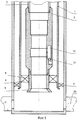
На фиг.1 схематически представлен продольный разрез колтюбинг-эжекторной установки при закачке в продуктивный пласт химических реактивов (кислотная обработка продуктивного пласта).Figure 1 schematically shows a longitudinal section of a coiled tubing-ejector installation during the injection of chemical reagents into the reservoir (acid treatment of the reservoir).
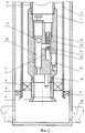
На фиг.2 схематически представлен продольный разрез колтюбинг-эжекторной установки с установленным в корпусе-опоре гидродинамическим эжектирующим устройством с автономным манометром.Figure 2 schematically shows a longitudinal section of a coiled tubing-ejector installation with a hydrodynamic ejection device installed in the support casing with an autonomous pressure gauge.
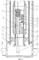
На фиг.3 схематически представлен продольный разрез колтюбинг-эжекторной установки с комплексным геофизическим прибором или перфоратором и установленным в корпусе-опоре геофизическим эжектирующим устройством.Figure 3 schematically shows a longitudinal section of a coiled tubing-ejector installation with a complex geophysical device or perforator and a geophysical ejection device installed in the support body.
Скважинная струйная установка содержит НКТ 1 с пакером 2, колонну гибких труб (КГТ) 3, на которой установлены последовательно снизу вверх хвостовик 4 с входной воронкой 5, пакер 6 и корпус-опора 7 для установки эжектирующих устройств, а именно гидродинамического эжектирующего устройства 8 и геофизического эжектирующего устройства 9. В корпусе-опоре 7 выполнен перепускной канал 10 с установленным в нем обратным клапаном 11. Гидродинамическое эжектирующее устройство 8 и геофизическое эжектирующее устройство 9 и выполнены с соплом 12 для подачи рабочего агента, сообщенным со стороны входа в него через перепускной канал 10 с затрубным пространством КГТ 3, камерой смешения 13, диффузором 14 и каналом 15 подвода откачиваемой среды. Гидродинамическое эжектирующее устройство 8 выполнено с установленным под ним автономным манометром 16 и установленным в канале 15 подвода откачиваемой среды обратным клапаном 17. Через канал 15 подвода откачиваемой среды геофизического эжектирующего устройства 9 пропущен каротажный кабель 18 для размещения в скважине ниже геофизического эжектирующего устройства 9 комплексного геофизического прибора 19 или малогабаритного перфоратора 20, при этом каротажный кабель 18 пропущен через установленный над каналом 15 подвода перекачиваемой среды герметизирующий узел 21 с возможностью перемещения относительно геофизического эжектирующего устройства 9.The downhole jet installation comprises a
В газлифтную нефтяную скважину с колонной НКТ и пакером спускают в НКТ на КГТ 3 установленные последовательно снизу вверх хвостовик 4 с входной воронкой 5, пакер 6 и корпус-опору 7 для эжектирующего устройства. Пакер 6 КГТ 3 располагают над пакером 2 НКТ 1, а входную воронку 5 - над кровлей продуктивного пласта 22. Проводят распакеровку пакера 6 КГТ 3 и через КГТ 3 и корпус-опору 7 закачивают в продуктивный пласт 22 кислотный раствор. А потом через КГТ 3 устанавливают в корпусе-опоре 7 гидродинамическое эжектирующее устройство 8 с установленным под ним автономным манометром 16. Путем подачи под давлением по кольцевому пространству между внешней поверхностью КГТ 3 и внутренней поверхностью НКТ 1 жидкого рабочего агента (нефть или конденсат) в сопло 12 гидродинамического эжектирующего устройства 8 создают депрессию на продуктивный пласт 22 и проводят дренирование его прискважинной зоны от продуктов реакции кислотного раствора с пластом. После откачки из продуктивного пласта 22 продуктов реакции резко прекращают подачу рабочего агента в сопло 12 гидродинамического эжектирующего устройства 8, при этом установленный в канале 15 подвода откачиваемой среды обратный клапан 17 гидродинамического эжектирующего устройства 8 автоматически закрывается, и проводят регистрацию кривой восстановления пластового давления (КВД) в подпакерном пространстве. После регистрации КВД с помощью канатной техники извлекают гидродинамическое эжектирующее устройство 8 с автономным манометром 16 на поверхность и через КГТ 3 в скважину на каротажном кабеле 18 спускают комплексный геофизический прибор 19 с подвижно установленным над ним на каротажном кабеле 18 геофизическим эжектирующим устройством 9. При спуске с помощью комплексного геофизического прибора 19 регистрируют фоновые геофизические параметры, например давление и температуру, вдоль ствола скважины от входной воронки 5 КГТ 3 до забоя скважины, при этом геофизическое эжектирующее устройство 9 устанавливают в корпусе-опоре 7. Далее путем подачи под давлением по кольцевому пространству между внешней поверхностью КГТ 3 и внутренней поверхностью НКТ 1 рабочего агента в сопло 12 геофизического эжектирующего устройства 9 создают депрессию на продуктивный пласт 22, дренируют продуктивный пласт 22 до момента стабилизации притока, а потом при работающем геофизическом эжектирующем устройстве 9 с помощью каротажного кабеля 18 поднимают комплексный геофизический прибор 19 от забоя до входной воронки 5 КГТ 3, регистрируя при этом геофизические параметры скважины. Прекращают работу геофизического эжектирующего устройства 9 и извлекают из скважины комплексный геофизический прибор 19 с геофизическим эжектирующим устройством 9 на поверхность, сбрасывают в КГТ 3 гидродинамическое эжектирующее устройство 8 с автономным манометром 16 и устанавливают его в корпусе-опоре 7. Путем подачи под давлением по кольцевому пространству между внешней поверхностью КГТ 3 и внутренней поверхностью НКТ 1 в сопло 12 гидродинамического эжектирующего устройства 8 природного газа создают депрессию на продуктивный пласт 22, под действием которой пластовый флюид, в частности нефть, через канал 15 подвода откачиваемой среды, зазор между срезом сопла 12 и срезом камеры смешения 13, камеру смешения 13 и диффузор 14 гидродинамического эжектирующего устройства 8 поступает в КГТ 3 и по ней вместе с природным газом поднимается на поверхность (эжекторный газлифт). Проводят добычу пластового флюида с помощью эжекторного газлифта. После падения дебита пластового флюида заменяют природный газ на нефть или конденсат, резко прекращают подачу рабочего агента в сопло 12 гидродинамического эжектирующего устройства 8 и проводят регистрацию КВД в подпакерном пространстве, после чего с помощью канатной техники извлекают гидродинамическое эжектирующее устройство 8 вместе с автономным манометром 16 на поверхность и на каротажном кабеле 18 спускают комплексный каротажный прибор 20 с подвижно установленным над ним геофизическим эжектирующим устройством 9 и с помощью комплексного каротажного прибора 20 исследуют интервал скважины от входной воронки 5 до забоя скважины при работающем геофизическом эжектирующем устройстве 9, регистрируя профили притока и определяя источники обводнения. Замещают жидкий рабочий агент на природный газ, прекращают подачу природного газа в сопло 12 геофизического эжектирующего устройства 9. Извлекают из скважины комплексный каротажный прибор 20 с геофизическим эжектирующим устройством 9 и проводят через КГТ 3 и корпус-опору 7 мероприятия для восстановления производительности скважины по пластовому флюиду: водоизоляционные работы, перестрел пласта в режиме депрессии с помощью малогабаритных перфораторов, спускаемых на каротажном кабеле 18, или кислотную обработку пласта 22, а потом повторные описанные выше гидродинамические и геофизические исследования и снова запускают скважину в работу с помощью эжекторного газлифта.In a gas-lift oil well with a tubing string and a packer, a
Изобретение может найти применение при испытании, освоении и эксплуатации нефтяных и газоконденсатных скважин, а также при их капитальном ремонте.The invention can find application in the testing, development and operation of oil and gas condensate wells, as well as in their overhaul.
Claims (1)
Priority Applications (1)
| Application Number | Priority Date | Filing Date | Title |
|---|---|---|---|
| RU2009133003/06A RU2404373C1 (en) | 2009-09-03 | 2009-09-03 | Method of operating coiled tubing-ejector plant in gas-lift oil well |
Applications Claiming Priority (1)
| Application Number | Priority Date | Filing Date | Title |
|---|---|---|---|
| RU2009133003/06A RU2404373C1 (en) | 2009-09-03 | 2009-09-03 | Method of operating coiled tubing-ejector plant in gas-lift oil well |
Publications (1)
| Publication Number | Publication Date |
|---|---|
| RU2404373C1 true RU2404373C1 (en) | 2010-11-20 |
Family
ID=44058486
Family Applications (1)
| Application Number | Title | Priority Date | Filing Date |
|---|---|---|---|
| RU2009133003/06A RU2404373C1 (en) | 2009-09-03 | 2009-09-03 | Method of operating coiled tubing-ejector plant in gas-lift oil well |
Country Status (1)
| Country | Link |
|---|---|
| RU (1) | RU2404373C1 (en) |
Cited By (4)
| Publication number | Priority date | Publication date | Assignee | Title |
|---|---|---|---|---|
| RU2459948C1 (en) * | 2011-03-14 | 2012-08-27 | Открытое акционерное общество "Газпром" | Interval treatment method of bottom-hole zone of oil-gas well formations (versions) |
| WO2014022611A1 (en) * | 2012-08-01 | 2014-02-06 | Schlumberger Canada Limited | Single well inject-produce pilot for eor |
| RU2642694C1 (en) * | 2016-09-01 | 2018-01-25 | Юлий Андреевич Гуторов | Method for investigation of horizontal wells |
| RU2828936C1 (en) * | 2024-06-26 | 2024-10-21 | Дмитрий Сергеевич Шубенок | Universal multifunctional device based on plug-in hydraulic jet ejector pump for oil field operations |
Citations (5)
| Publication number | Priority date | Publication date | Assignee | Title |
|---|---|---|---|---|
| RU2129671C1 (en) * | 1998-03-11 | 1999-04-27 | Зиновий Дмитриевич Хоминец | Method of operation of oil-well jet unit |
| CA2261415A1 (en) * | 1998-02-11 | 1999-08-11 | Anthony Walby Wakefield | Method and apparatus for extracting oil |
| GB2410044A (en) * | 2004-01-15 | 2005-07-20 | Schlumberger Holdings | Combined jet pump and safety valve unit for simple deployment and retrieval |
| RU2303171C1 (en) * | 2006-03-22 | 2007-07-20 | Зиновий Дмитриевич Хоминец | Well jet plant for logging operations and method for operating the same |
| RU2334131C1 (en) * | 2007-07-18 | 2008-09-20 | Зиновий Дмитриевич Хоминец | Well jet unit "эмпи-угис-(31-40)ш" |
-
2009
- 2009-09-03 RU RU2009133003/06A patent/RU2404373C1/en not_active IP Right Cessation
Patent Citations (5)
| Publication number | Priority date | Publication date | Assignee | Title |
|---|---|---|---|---|
| CA2261415A1 (en) * | 1998-02-11 | 1999-08-11 | Anthony Walby Wakefield | Method and apparatus for extracting oil |
| RU2129671C1 (en) * | 1998-03-11 | 1999-04-27 | Зиновий Дмитриевич Хоминец | Method of operation of oil-well jet unit |
| GB2410044A (en) * | 2004-01-15 | 2005-07-20 | Schlumberger Holdings | Combined jet pump and safety valve unit for simple deployment and retrieval |
| RU2303171C1 (en) * | 2006-03-22 | 2007-07-20 | Зиновий Дмитриевич Хоминец | Well jet plant for logging operations and method for operating the same |
| RU2334131C1 (en) * | 2007-07-18 | 2008-09-20 | Зиновий Дмитриевич Хоминец | Well jet unit "эмпи-угис-(31-40)ш" |
Cited By (4)
| Publication number | Priority date | Publication date | Assignee | Title |
|---|---|---|---|---|
| RU2459948C1 (en) * | 2011-03-14 | 2012-08-27 | Открытое акционерное общество "Газпром" | Interval treatment method of bottom-hole zone of oil-gas well formations (versions) |
| WO2014022611A1 (en) * | 2012-08-01 | 2014-02-06 | Schlumberger Canada Limited | Single well inject-produce pilot for eor |
| RU2642694C1 (en) * | 2016-09-01 | 2018-01-25 | Юлий Андреевич Гуторов | Method for investigation of horizontal wells |
| RU2828936C1 (en) * | 2024-06-26 | 2024-10-21 | Дмитрий Сергеевич Шубенок | Universal multifunctional device based on plug-in hydraulic jet ejector pump for oil field operations |
Similar Documents
| Publication | Publication Date | Title |
|---|---|---|
| RU2334131C1 (en) | Well jet unit "эмпи-угис-(31-40)ш" | |
| WO2007149008A1 (en) | Method for operating a well jet device at a hydraulic fracturing of multilayer hydrocarbon reservoirs | |
| RU2404373C1 (en) | Method of operating coiled tubing-ejector plant in gas-lift oil well | |
| RU2190779C1 (en) | Oil-well jet plant for testing and completion of oil wells and method of plant operation | |
| RU2246049C1 (en) | Well pumping unit for operation in horizontal wells | |
| WO2006068535A1 (en) | Method for operating a well jet device in the conditions of a formation hydraulic fracturing | |
| EA005687B1 (en) | Method for operating a well jet device during cleaning of the downhole area of a formation and device for carrying out said method | |
| WO2007126331A1 (en) | Method for operating a jet device for developing and operating oil- and-gas wells | |
| RU2404374C1 (en) | Method of operating well injection plant in testing multipay wells | |
| RU2473821C1 (en) | Borehole jetting unit for hydrofrac and well tests | |
| RU2263784C1 (en) | Ejectional multi-purpose formation tester for horizontal wells and operational method therefore | |
| RU2345214C2 (en) | Method of oil and gas influx development and intensification, waterproofing procedure and related device for implementation thereof | |
| EA200501656A1 (en) | WELL JET INSTALLATION AND METHOD OF ITS WORK UNDER CAROSING HORIZONTAL WELLS | |
| RU2256103C1 (en) | Method of operation of horizontal well ejector multifunctional formation tester | |
| RU2239730C1 (en) | Oil-well jet plant for logging horizontal wells and method of its operation | |
| RU2374503C1 (en) | Downhole jet unit for perforation of benches, intensification of inflow and oil-and-gas well development | |
| RU2631580C1 (en) | Well jet plant for selective testing of formations | |
| RU2263237C1 (en) | Method for borehole jet plant operation during gas production from gas-condensate well | |
| RU2206801C1 (en) | Way of operation of down-hole jet-type plant in process of acidic treatment of formation | |
| RU2253761C1 (en) | Method of operation of well jet plant at horizontal well logging | |
| RU2263236C1 (en) | Method of and plant for operating jet unit at hydraulic fracturing of formation | |
| RU2307928C1 (en) | Method for operation of well jet plant during logging of horizontal wells | |
| RU2206800C1 (en) | Down-hole jet plant for acidizing of formations | |
| RU2256102C1 (en) | Ejector multifunctional formation tester for testing and completion of horizontal wells | |
| RU2252338C1 (en) | Method to prepare well jet plant for logging horizontal wells |
Legal Events
| Date | Code | Title | Description |
|---|---|---|---|
| MM4A | The patent is invalid due to non-payment of fees |
Effective date: 20150904 |