RU2256103C1 - Method of operation of horizontal well ejector multifunctional formation tester - Google Patents
Method of operation of horizontal well ejector multifunctional formation tester Download PDFInfo
- Publication number
- RU2256103C1 RU2256103C1 RU2004115857/06A RU2004115857A RU2256103C1 RU 2256103 C1 RU2256103 C1 RU 2256103C1 RU 2004115857/06 A RU2004115857/06 A RU 2004115857/06A RU 2004115857 A RU2004115857 A RU 2004115857A RU 2256103 C1 RU2256103 C1 RU 2256103C1
- Authority
- RU
- Russia
- Prior art keywords
- packer
- jet pump
- pipe string
- reservoir
- well
- Prior art date
Links
Images
Landscapes
- Sampling And Sample Adjustment (AREA)
Abstract
Description
Изобретение относится к области насосной техники, преимущественно к скважинным насосным установкам для добычи и интенсификации притока нефти из скважин.The invention relates to the field of pumping technology, mainly to downhole pumping units for production and intensification of oil flow from wells.
Известен способ работы скважинной струйной установки, включающий спуск в скважину колонны труб со струйным насосом, пакером и излучателем с приемником-преобразователем физических полей с размещением последнего ниже струйного насоса (см. патент RU 2129671, МПК 7 F 04 F 5/02, 27.04.1999).A known method of operation of a downhole jet installation, which includes lowering a string of pipes with a jet pump, a packer and an emitter with a receiver-transducer of physical fields into the well with the latter located below the jet pump (see patent RU 2129671, IPC 7 F 04 F 5/02, 27.04. 1999).
Данный способ работы позволяет проводить откачку из скважины различных добываемых сред, например нефти, с одновременным исследованием скважины, при этом излучатель и приемник-преобразователь физических полей размещен с возможностью возвратно-поступательного перемещения вдоль оси скважины относительно струйного насоса и пласта, однако в ряде случаев этого недостаточно, чтобы получить полную информацию о состоянии скважины, что снижает эффективность проводимой работы по интенсификации добычи нефти из скважины.This method of operation allows pumping various produced media, for example oil, from the well, while simultaneously exploring the well, while the emitter and receiver-transducer of physical fields are placed with the possibility of reciprocating movement along the axis of the well relative to the jet pump and reservoir, however, in some cases this not enough to get complete information about the condition of the well, which reduces the effectiveness of the work to intensify oil production from the well.
Наиболее близким к изобретению по технической сущности и достигаемому результату является способ работы скважинной струйной установки, включающий установку на колонне труб пакера и струйного насоса, в корпусе которого выполнен проходной канал с посадочным местом, спуск этой сборки в скважину, распакеровку пакера и размещение в скважине ниже струйного насоса глубинных приборов (см. патент RU 2129672 С1, МПК 7 F 04 F 5/02, 27.04.1999).The closest to the invention in technical essence and the achieved result is a method of operating a downhole jet installation, comprising installing a packer and an jet pump on a pipe string, in the housing of which there is a passage channel with a seat, lowering this assembly into the well, unpacking the packer and placing it in the well below deep-well jet pump (see patent RU 2129672 C1, IPC 7 F 04 F 5/02, 04/27/1999).
Данный способ работы скважинной струйной установки позволяет проводить различные технологические операции в скважине ниже уровня установки струйного насоса, в том числе путем создания перепада давлений над и под герметизирующим узлом. Однако данный способ работы установки не позволяет в полной мере использовать ее возможности, что связано с ограниченным набором операций по интенсификации притока из продуктивного пласта.This method of operation of a downhole jet installation allows for various technological operations in the well below the installation level of the jet pump, including by creating a pressure differential above and below the sealing unit. However, this method of operation of the installation does not allow to fully use its capabilities, which is associated with a limited set of operations to intensify the influx from the reservoir.
Задачей, на решение которой направлено настоящее изобретение, является повышение производительности и интенсификация работ по исследованию и испытанию скважин с открытым и обсаженным стволом, в первую очередь, с криволинейным или горизонтальным стволом, оптимизация совместной работы пакера, струйного насоса и автономного каротажного комплекса и за счет этого повышение надежности работы эжекторного многофункционального пластоиспытателя для горизонтальных скважин при повышении достоверности геолого-промысловой информации, получаемой в ходе проведения испытаний скважин.The problem to which the present invention is directed, is to increase productivity and intensify research and testing of open and cased hole wells, primarily with a curved or horizontal well, optimization of the joint work of the packer, jet pump and autonomous logging complex and due to this increase the reliability of the ejector multifunctional reservoir tester for horizontal wells while increasing the reliability of geological information obtained second during the well test.
Указанная задача решается за счет того, что способ работы эжекторного многофункционального пластоиспытателя для горизонтальных скважин заключается в том, что на колонне труб последовательно монтируют струйный насос, в корпусе которого выполнен ступенчатый проходной канал с посадочным местом между ступенями с возможностью установки на посадочное место сменных функциональных вставок, верхний механический пакер, нижний пакер из эластичного материала, выполненный в виде стакана с конуснообразной расширяющейся вверх боковой стенкой, центрующее кольцо, а на нижнем конце колонны труб с перфорированным участком устанавливают автономный каротажный комплекс, спускают эту сборку на колонне труб в скважину, причем в ходе спуска проводят регистрацию с помощью автономного каротажного комплекса фоновых значений физических полей горных пород, после достижения автономным каротажным комплексом проектной глубины проводят распакеровку верхнего механического пакера и устанавливают в ступенчатом проходном канале струйного насоса функциональную вставку для регистрации кривых восстановления пластового давления, далее путем подачи жидкой рабочей среды в сопло струйного насоса создают в подпакерной зоне не менее трех ступенчато увеличивающихся значений депрессий на пласт и, замеряя на поверхности объемы жидкости, откачанной за время действия каждой депрессии, определяют дебиты откачиваемой из пласта жидкой среды, потом дополнительно создают депрессию на пласт и поддерживают ее в течение времени, необходимого для создания воронки депрессии, а далее с помощью функциональной вставки для регистрации кривых восстановления пластового давления проводят регистрацию кривой восстановления пластового давления в подпакерном пространстве скважины, затем приводят верхний механический пакер в транспортное положение и подают в сопла струйного насоса жидкую рабочую среду, приводя таким образом нижний пакер в рабочее положение, далее дренирут пласт в течение 2-4 часов, а потом при работающем струйном насосе проводят подъем сборки колонны труб и регистрируют при этом с помощью автономного каротажного комплекса физические поля горных пород вдоль ствола скважины, после чего извлекают из струйного насоса функциональную вставку для регистрации кривых восстановления пластового давления и устанавливают в ступенчатом проходном канале блокирующую вставку со сквозным центральным каналом, опускают сборку на колонне труб до достижения автономным каротажным комплексом нижнего интервала перфорации пласта, закачивают в скважину через внутреннюю полость колонны труб кислотный раствор или жидкость гидроразрыва и при достижении закачанной жидкой средой верхнего интервала перфорации продуктивного пласта проводят распакеровку верхнего механического пакера и задавливают кислотный раствор в пласт или проводят гидроразрыв пласта, затем извлекают блокирующую вставку и устанавливают в ступенчатом проходном канале функциональную вставку для регистрации кривых восстановления пластового давления, дренируют скважину, в процессе чего откачивают из скважины продукты реакции или жидкость гидроразрыва, а затем проводят регистрацию кривой восстановления пластового давления в подпакерном пространстве скважины, после чего приводят верхний пакер в транспортное положение, подают в сопло струйного насоса жидкую рабочую среду, приводят таким образом нижний пакер в рабочее положение и создают депрессию на пласт в течение 2-4 часов, а потом при работающем струйном насосе проводят подъем сборки на колонне труб и регистрируют при этом с помощью автономного каротажного комплекса физические поля горных пород.This problem is solved due to the fact that the method of operation of the ejector multifunctional reservoir tester for horizontal wells consists in the fact that a jet pump is successively mounted on the pipe string, in the housing of which there is a stepped passage channel with a seat between the steps with the possibility of installing replaceable functional inserts on the seat , upper mechanical packer, lower packer made of elastic material, made in the form of a glass with a cone-shaped side wall expanding upwards, a thrust ring, and at the lower end of the pipe string with a perforated section, an autonomous logging complex is installed, this assembly is lowered onto the pipe string into the well, and during the descent, the background values of the rock physical fields are recorded using the autonomous logging complex, after the autonomous logging complex reaches the design depths, unpack the upper mechanical packer and install a functional insert in the stepped passage channel of the jet pump for recording curves in formation pressure recovery, then by supplying a liquid working medium to the nozzle of the jet pump, at least three stepwise increasing depressions on the formation are created in the sub-packer zone and, measuring surface volumes of the fluid pumped out during the duration of each depression, the flow rates of the liquid medium pumped out of the formation are determined, then additionally create a depression on the formation and maintain it for the time necessary to create a funnel of depression, and then using a functional insert to record recovery curves the formation pressure curve, the formation pressure recovery curve is recorded in the under-packer space of the well, then the upper mechanical packer is brought into the transport position and the liquid medium is fed into the nozzles of the jet pump, thereby bringing the lower packer into working position, then the formation is drained for 2-4 hours and then, when the jet pump is running, the assembly of the pipe string is carried out and the physical fields of rocks along the well bore are recorded using an autonomous logging complex fluid, after which a functional insert is removed from the jet pump to register formation pressure recovery curves and a blocking insert with a through central channel is installed in the stepped passage channel, the assembly is lowered on the pipe string until the autonomous logging complex reaches the lower interval of formation perforation, and is pumped into the well through the internal cavity pipe string acid solution or fracturing fluid and when the pumped fluid reaches the upper perforation interval the reservoir, the upper mechanical packer is unpacked and the acid solution is crushed into the reservoir or hydraulic fracturing is carried out, then the blocking insert is removed and a functional insert is installed in the stepped passage channel to register formation pressure recovery curves, the well is drained, during which reaction products or hydraulic fracturing are pumped out of the well and then the formation pressure recovery curve is recorded in the sub-packer space of the well, after which the top packer in the transport position, liquid working medium is fed into the nozzle of the jet pump, the lower packer is thus brought into working position and depressed onto the formation for 2-4 hours, and then when the jet pump is running, the assembly is lifted on the pipe string and recorded at with the help of an autonomous logging complex, physical fields of rocks.
Кроме того, перед последним подъемом сборки колонны труб может быть проведено дополнительное исследование продуктивных пластов, для чего по колонне труб через ее перфорированный нижний участок закачивают в зону продуктивного пласта жидкость с аномальными физическими свойствами, например с высокой электропроводностью, а после этого в процессе подъема сборки на колонне труб проводят исследование продуктивных пластов вдоль ствола скважины с помощью автономного каротажного комплекса.In addition, before the last rise in the assembly of the pipe string, an additional study of the productive formations can be carried out, for which liquid with abnormal physical properties, for example, with high electrical conductivity, is pumped through the perforated lower section of the pipe string into the zone of the productive formation, and then during the process of lifting the assembly On the pipe string, productive formations are studied along the wellbore using an autonomous logging complex.
Анализ работы эжекторного многофункционального пластоиспытателя, посредством которого реализуется описываемый способ его работы, показал, что надежность работы установки можно повысить как путем оптимизации последовательности и набора операций по интенсификации притока путем организации работы установки с двумя пакерами, один из которых механический или гидромеханический, а другой расположен ниже, выполнен из эластичного материала и снабжен расположенным ниже него на колонне труб центрующим его в обсадной колонне кольцом.An analysis of the operation of the ejector multifunctional formation tester, by means of which the described method of its operation is implemented, showed that the reliability of the installation can be improved both by optimizing the sequence and set of operations to intensify the inflow by organizing the installation with two packers, one of which is mechanical or hydromechanical, and the other is located below, it is made of elastic material and is equipped with a ring located below it on the pipe string and centering it in the casing string.
Было выявлено, что указанное выше расположение струйного насоса в скважине позволяет наиболее эффективно использовать оборудование, которое установлено на колонне труб, при проведении работ по исследованию и испытанию продуктивных пластов горных пород, при этом созданы условия для получения полной и достоверной информации о состоянии продуктивных пластов. Создание ряда различных депрессий на продуктивный пласт с помощью струйного насоса и регистрация кривых восстановления пластового давления с помощью предназначенной для этого функциональной вставки и с помощью автономного каротажного комплекса позволяет повысить объем получаемой информации о состоянии продуктивного пласта. Контроль величины депрессии путем управления скоростью прокачки жидкой рабочей среды с созданием строго определенной, заранее рассчитанной депрессии позволяет повысить точность получаемой информации. Регулировку режима откачки при проведении испытания пластов осуществляют посредством изменения давления жидкой рабочей среды, подаваемой в сопло струйного насоса. В ходе проведения испытаний используют два конструктивно различающихся пакера, что позволило расширить методику проведения испытаний и повысить достоверность получаемой информации. Было установлено, что проведение регистрации кривых восстановления пластового давления и длительного дренирования пласта целесообразно проводить при распакерованном механическом или гидромеханическом пакере, а каротаж пласта в режиме депрессии - при нахождении механического или гидромеханического пакера в транспортном положении. В этом случае разобщение пространства скважины осуществляется посредством дополнительного пакера из эластичного материала. Это связано с тем, что фиксированное положение элементов конструкции установки позволяет снизить погрешность при снятии гидродинамических характеристик скважины, а разобщение пространства скважины с помощью пакера из эластичного материала позволяет проводить динамические испытания пласта, причем представляется возможность в ходе этих исследований перемещать относительно скважины струйный насос совместно с автономным каротажным комплексом и таким образом проводить каротаж при депрессии на пласт. В ходе исследования было установлено, что целесообразно проводить длительное дренирование в течение 2-4 часов. Более короткое время дренирования не позволяет оказать качественное воздействие на пласт, а более длительное воздействие не дает ощутимых результатов, но при этом ведет к увеличению времени проведения работ и увеличению эксплуатационных расходов. Проведение разнообразных комплексных исследований позволяет расширить объем получаемой информации в ходе одного спуска установки в скважину. Однако было установлено, что более рационально размещение пакера из эластичного материала ниже механического или гидромеханического пакера. В этом случае снижается нагрузка на пакер из эластичного материала при создании максимальных перепадов давления на пакере. Установка в ступенчатом проходном канале струйного насоса других функциональных вставок, в частности блокирующей вставки, дает возможность перекрывать блокирующей вставкой канал подачи жидкой рабочей среды и канал подвода откачиваемой из скважины среды при проведении работ по разобщению затрубного и внутритрубного пространства скважины, что позволяет предотвратить попадание в струйный насос посторонних предметов, которые могут засорить струйный насос, что также позволяет повысить надежность работы установки. Дополнительное повышение точности получаемых данных при регистрации указанных выше кривых достигается путем выполнения функциональной вставки для регистрации кривых восстановления пластового давления с обратным клапаном и перепускным клапаном, что, в свою очередь, позволяет провести более качественную обработку скважины и подготовку ее к эксплуатации, а также позволяет ускорить и упростить процесс выравнивания давления между подпакерным и надпакерным пространством скважины. Таким образом, данный способ работы эжекторного многофункционального пластоиспытателя имеет широкие функциональные возможности, что позволяет проводить качественное исследование и испытание скважин после бурения или при капитальном ремонте с проведением всестороннего исследования и испытания в различных режимах.It was found that the above location of the jet pump in the well allows the most efficient use of the equipment installed on the pipe string when conducting research and testing of productive rock formations, while conditions were created for obtaining complete and reliable information about the state of the productive formations. Creating a number of different depressions on the reservoir using a jet pump and recording the recovery curves of the reservoir pressure using the intended for this functional insert and using the autonomous logging system allows you to increase the amount of information received on the state of the reservoir. Monitoring the magnitude of depression by controlling the rate of pumping of the liquid working medium with the creation of a well-defined, pre-calculated depression allows you to increase the accuracy of the information received. The adjustment of the pumping mode during the formation testing is carried out by changing the pressure of the liquid working medium supplied to the nozzle of the jet pump. During the tests, two structurally different packers are used, which allowed to expand the test procedure and increase the reliability of the information received. It was found that the registration of the curves of reservoir pressure restoration and long-term drainage of the formation should be carried out with the unpacked mechanical or hydromechanical packer, and formation logging in the depressed mode when the mechanical or hydromechanical packer is in the transport position. In this case, the separation of the space of the well is carried out by means of an additional packer of elastic material. This is due to the fact that the fixed position of the structural elements of the installation allows to reduce the error when taking the hydrodynamic characteristics of the well, and the separation of the space of the well using a packer of elastic material allows dynamic formation testing, and it is possible during these studies to move the jet pump relative to the well together with autonomous logging complex and thus logging with depression on the reservoir. During the study, it was found that it is advisable to carry out long-term drainage for 2-4 hours. A shorter drainage time does not allow a qualitative impact on the formation, and a longer exposure does not produce tangible results, but at the same time leads to an increase in the time of work and an increase in operating costs. Conducting a variety of comprehensive studies allows you to expand the amount of information obtained during one descent of the installation into the well. However, it was found that it is more rational to place a packer of elastic material below a mechanical or hydromechanical packer. In this case, the load on the packer of elastic material is reduced while creating maximum pressure drops on the packer. The installation of other functional inserts in the stepped passage channel of the jet pump, in particular a blocking insert, makes it possible to block the channel for supplying the liquid working medium and the channel for supplying the medium pumped out from the well during the separation of the annular and in-tube space of the well, which prevents the well from entering the jet pump of foreign objects that can clog the jet pump, which also improves the reliability of the installation. An additional increase in the accuracy of the data obtained during the registration of the above curves is achieved by performing a functional insert to register the reservoir pressure recovery curves with a check valve and a bypass valve, which, in turn, allows for better processing of the well and its preparation for operation, as well as accelerates and simplify the process of balancing the pressure between the sub-packer and over-packer space of the well. Thus, this method of operation of an ejector multifunctional reservoir tester has wide functional capabilities, which allows for high-quality exploration and testing of wells after drilling or during overhaul with comprehensive research and testing in various modes.
Таким образом, указанная выше совокупность взаимозависимых параметров со строго определенной последовательностью операций с продуктивным пластом обеспечивает достижение выполнения поставленной в изобретении задачи - интенсификации работ по исследованию и испытанию криволинейных и горизонтальных скважин с открытым и обсаженным стволом в зоне продуктивного пласта, а также оптимизации работы пакеров при их работе совместно со струйным насосом и автономным каротажным комплексом и за счет этого повышения надежности работы скважинной струйной установки.Thus, the above set of interdependent parameters with a strictly defined sequence of operations with the reservoir ensures the achievement of the objectives of the invention - the intensification of research and testing of curved and horizontal wells with open and cased holes in the zone of the reservoir, as well as optimizing the work of packers at their work in conjunction with a jet pump and an autonomous logging complex and due to this increase the reliability of the well truynoy installation.
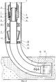
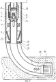
На фиг.1 представлен продольный разрез эжекторного многофункционального пластоиспытателя с установленной функциональной вставкой для регистрации кривых восстановления пластового давления. На фиг.2 представлен продольный разрез эжекторного многофункционального пластоиспытателя с установленной блокирующей вставкой. На фиг.3 представлен продольный разрез эжекторного многофункционального пластоиспытателя с распакерованным нижним пакером.Figure 1 shows a longitudinal section of an ejector multifunctional reservoir tester with a functional insert installed to record the recovery curves of reservoir pressure. Figure 2 presents a longitudinal section of an ejector multifunctional formation tester with a blocking insert installed. Figure 3 presents a longitudinal section of an ejector multifunctional tester with an unpacked lower packer.
Эжекторный многофункциональный пластоиспытатель содержит установленные на колонне труб 1 механический или гидромеханический пакер 2, струйный насос 3, в корпусе 4 которого установлены сопло 5 и камера смешения 6 с диффузором 7, а также выполнен ступенчатый проходной канал 8 и канал подвода откачиваемой среды 17. В ступенчатом проходном канале 8 могут быть установлены функциональные вставки, в частности функциональная вставка 9 для регистрации кривых восстановления пластового давления с подключенным к ней каротажным кабелем 16, а также блокирующая вставка 18. Ниже пакера 2 на колонне труб 1 установлены автономный каротажный комплекс 10 для измерения физических величин, например удельного электрического сопротивления горных пород или воздействия на пласт физическими полями, например акустическими, и дополнительный пакер 11 из эластичного материала.The ejector multifunctional reservoir tester contains a mechanical or
Струйный насос 3 установлен в обсадной колонне 12 над продуктивным пластом 19 скважины. Ниже дополнительного пакера 11 на колонне труб 1 расположено центрующее пакер 11 в обсадной колонне 12 кольцо 13. В центрующем кольце 13 выполнены сквозные отверстия 14, а в колонне труб 1 над автономным каротажным комплексом 10 выполнены отверстия 15.The
Способ работы эжекторного многофункционального пластоиспытателя для горизонтальных скважин заключается в том, что на колонне труб 1 последовательно монтируют струйный насос 3, в корпусе 4 которого выполнен ступенчатый проходной канал 8 с посадочным местом между ступенями с возможностью установки на посадочное место сменных функциональных вставок, верхний механический или гидромеханический пакер 2, нижний пакер 11 из эластичного материала, выполненный в виде стакана с конуснообразной расширяющейся вверх боковой стенкой, центрующее кольцо 13, а на нижнем конце колонны труб 1 устанавливают автономный каротажный комплекс 10. Эту сборку спускают на колонне труб 1 в скважину, причем в ходе спуска проводят регистрацию фоновых значений физических полей горных пород автономным каротажным комплексом 10. После достижения автономным каротажным комплексом 10 проектной глубины проводят распакеровку верхнего пакера 2 и устанавливают в ступенчатом проходном канале 8 струйного насоса 3 функциональную вставку 9 для регистрации кривых восстановления пластового давления. Путем подачи жидкой рабочей среды в сопло 5 струйного насоса 3 создают в подпакерной зоне не менее трех ступенчато увеличивающихся значений депрессий на пласт и, замеряя на поверхности объемы жидкости, откаченной за время действия каждой депрессии, определяют дебиты откачиваемой из пласта жидкой среды. Потом дополнительно создают депрессию на пласт 19 и поддерживают ее в течение времени, необходимого для создания воронки депрессии, а далее с помощью функциональной вставки 9 для регистрации кривых восстановления пластового давления проводят регистрацию кривой восстановления пластового давления в подпакерном пространстве скважины. Затем приводят верхний пакер 2 в транспортное положение и подают в сопло 5 струйного насоса жидкую рабочую среду, приводя таким образом нижний пакер 11 в рабочее положение. Далее дренирут пласт 19 в течение 2-4 часов, а потом при работающем струйном насосе 3 проводят подъем сборки колонны труб 1 и регистрируют при этом с помощью автономного каротажного комплекса 10 физические поля горных пород, после чего извлекают из корпуса 4 струйного насоса 3 функциональную вставку 5 для регистрации кривых восстановления пластового давления и устанавливают в ступенчатом проходном канале 8 блокирующую вставку 18 со сквозным центральным каналом. Опускают сборку на колонне труб 1 до достижения автономным каротажным комплексом 10 нижнего интервала перфорации пласта. Закачивают в скважину через внутреннюю полость колонны труб 1 кислотный раствор или жидкость гидроразрыва и при достижении закачанной жидкой средой верхнего интервала перфорации продуктивного пласта 19 проводят распакеровку верхнего пакера 2 и задавливают кислотный раствор в пласт 19 или проводят гидроразрыв пласта 19. Затем извлекают блокирующую вставку 18 и устанавливают в ступенчатом проходном канале 8 депрессионную вставку или функциональную вставку 9 для регистрации кривых восстановления пластового давления. После этого проводят дренирование пласта скважины, в процессе которого откачивают из скважины продукты реакции или жидкость гидроразрыва. Затем проводят регистрацию кривой восстановления пластового давления в подпакерном пространстве скважины, после чего приводят верхний пакер 2 в транспортное положение, подают в сопло 5 струйного насоса 3 жидкую рабочую среду, приводят таким образом нижний пакер 11 в рабочее положение и создают депрессию на пласт в течение 2-4 часов. После этого проводят подъем сборки на колонне труб 1 при работающем струйном насосе 3 и регистрируют при этом физические поля горных пород с помощью автономного каротажного комплекса 10.The method of operation of an ejector multifunctional formation tester for horizontal wells consists in the fact that a
Настоящее изобретение может быть использовано в нефтедобывающей и горной промышленности при испытании нефтегазовых скважин на этапе их бурения и эксплуатации.The present invention can be used in the oil and mining industries when testing oil and gas wells at the stage of their drilling and operation.
Claims (2)
Priority Applications (2)
| Application Number | Priority Date | Filing Date | Title |
|---|---|---|---|
| RU2004115857/06A RU2256103C1 (en) | 2004-05-27 | 2004-05-27 | Method of operation of horizontal well ejector multifunctional formation tester |
| PCT/RU2005/000050 WO2005103501A1 (en) | 2004-04-21 | 2005-02-09 | Ejector multifunctional formation tester for horizontal wells and operation method thereof |
Applications Claiming Priority (1)
| Application Number | Priority Date | Filing Date | Title |
|---|---|---|---|
| RU2004115857/06A RU2256103C1 (en) | 2004-05-27 | 2004-05-27 | Method of operation of horizontal well ejector multifunctional formation tester |
Publications (1)
| Publication Number | Publication Date |
|---|---|
| RU2256103C1 true RU2256103C1 (en) | 2005-07-10 |
Family
ID=35838435
Family Applications (1)
| Application Number | Title | Priority Date | Filing Date |
|---|---|---|---|
| RU2004115857/06A RU2256103C1 (en) | 2004-04-21 | 2004-05-27 | Method of operation of horizontal well ejector multifunctional formation tester |
Country Status (1)
| Country | Link |
|---|---|
| RU (1) | RU2256103C1 (en) |
Cited By (4)
| Publication number | Priority date | Publication date | Assignee | Title |
|---|---|---|---|---|
| WO2007091917A1 (en) * | 2006-02-08 | 2007-08-16 | Zinoviy Dmitrievich Khomynets | Well jet device for horizontal wells and the operating method thereof |
| RU2324843C1 (en) * | 2006-11-29 | 2008-05-20 | Зиновий Дмитриевич Хоминец | Bore hole jet stream installation эмпи-угис-(1-10)кд - for logging and tests of horisontal bores |
| RU2341692C1 (en) * | 2007-10-10 | 2008-12-20 | Зиновий Дмитриевич Хоминец | Well jet facility for hydro-break-up of reservoir and reserch of horizontal wells and method of this facility employment |
| RU2384757C1 (en) * | 2008-12-08 | 2010-03-20 | Зиновий Дмитриевич Хоминец | Method of operation of downhole jet installation in flowing well with abnormally low seam pressure |
Citations (5)
| Publication number | Priority date | Publication date | Assignee | Title |
|---|---|---|---|---|
| US4293283A (en) * | 1977-06-06 | 1981-10-06 | Roeder George K | Jet with variable throat areas using a deflector |
| US4744730A (en) * | 1986-03-27 | 1988-05-17 | Roeder George K | Downhole jet pump with multiple nozzles axially aligned with venturi for producing fluid from boreholes |
| RU2059891C1 (en) * | 1989-06-14 | 1996-05-10 | Зиновий Дмитриевич Хоминец | Borehole jet set |
| RU2129672C1 (en) * | 1998-06-19 | 1999-04-27 | Зиновий Дмитриевич Хоминец | Jet-type oil-well unit (versions) |
| RU2129671C1 (en) * | 1998-03-11 | 1999-04-27 | Зиновий Дмитриевич Хоминец | Method of operation of oil-well jet unit |
-
2004
- 2004-05-27 RU RU2004115857/06A patent/RU2256103C1/en not_active IP Right Cessation
Patent Citations (5)
| Publication number | Priority date | Publication date | Assignee | Title |
|---|---|---|---|---|
| US4293283A (en) * | 1977-06-06 | 1981-10-06 | Roeder George K | Jet with variable throat areas using a deflector |
| US4744730A (en) * | 1986-03-27 | 1988-05-17 | Roeder George K | Downhole jet pump with multiple nozzles axially aligned with venturi for producing fluid from boreholes |
| RU2059891C1 (en) * | 1989-06-14 | 1996-05-10 | Зиновий Дмитриевич Хоминец | Borehole jet set |
| RU2129671C1 (en) * | 1998-03-11 | 1999-04-27 | Зиновий Дмитриевич Хоминец | Method of operation of oil-well jet unit |
| RU2129672C1 (en) * | 1998-06-19 | 1999-04-27 | Зиновий Дмитриевич Хоминец | Jet-type oil-well unit (versions) |
Cited By (8)
| Publication number | Priority date | Publication date | Assignee | Title |
|---|---|---|---|---|
| WO2007091917A1 (en) * | 2006-02-08 | 2007-08-16 | Zinoviy Dmitrievich Khomynets | Well jet device for horizontal wells and the operating method thereof |
| RU2324843C1 (en) * | 2006-11-29 | 2008-05-20 | Зиновий Дмитриевич Хоминец | Bore hole jet stream installation эмпи-угис-(1-10)кд - for logging and tests of horisontal bores |
| WO2008066412A1 (en) * | 2006-11-29 | 2008-06-05 | Zinoviy Dmitrievich Khomynets | Well jet device logging and testing horizontal wells |
| RU2341692C1 (en) * | 2007-10-10 | 2008-12-20 | Зиновий Дмитриевич Хоминец | Well jet facility for hydro-break-up of reservoir and reserch of horizontal wells and method of this facility employment |
| WO2009048351A1 (en) * | 2007-10-10 | 2009-04-16 | Zinoviy Dmitrievich Khomynetz | Bore-hole jet device for formation hydraulic fracturing and horizontal well examination and a method for the operation thereof |
| EA016047B1 (en) * | 2007-10-10 | 2012-01-30 | Зиновий Дмитриевич ХОМИНЕЦ | Bore-hole jet device for formation hydraulic fracturing and horizontal well examination and a method for the operation thereof |
| US8397808B2 (en) | 2007-10-10 | 2013-03-19 | Zinoviy Dmitrievich Khomynets | Bore-hole jet device for formation hydraulic fracturing and horizontal well examination and a method for the operation thereof |
| RU2384757C1 (en) * | 2008-12-08 | 2010-03-20 | Зиновий Дмитриевич Хоминец | Method of operation of downhole jet installation in flowing well with abnormally low seam pressure |
Similar Documents
| Publication | Publication Date | Title |
|---|---|---|
| WO2009048351A1 (en) | Bore-hole jet device for formation hydraulic fracturing and horizontal well examination and a method for the operation thereof | |
| RU2372530C1 (en) | Borehole jet system for logging and developing horizontal wells with abnormal low formation pressures | |
| RU2188342C1 (en) | Method of operation of well jet plant at testing and completion of wells, and well jet plant | |
| WO2007149008A1 (en) | Method for operating a well jet device at a hydraulic fracturing of multilayer hydrocarbon reservoirs | |
| RU2273772C1 (en) | Method of operation of oil-well jet plant at hydraulic fracturing of formation | |
| CN109322644B (en) | Pressure-control drainage gas production method and system for coal-bed gas well | |
| RU2256103C1 (en) | Method of operation of horizontal well ejector multifunctional formation tester | |
| WO2007126331A1 (en) | Method for operating a jet device for developing and operating oil- and-gas wells | |
| RU2263784C1 (en) | Ejectional multi-purpose formation tester for horizontal wells and operational method therefore | |
| RU2303172C1 (en) | Well jet plant and its operation method | |
| RU2404373C1 (en) | Method of operating coiled tubing-ejector plant in gas-lift oil well | |
| RU2404374C1 (en) | Method of operating well injection plant in testing multipay wells | |
| RU2510456C2 (en) | Formation method of vertically directed fracture at hydraulic fracturing of productive formation | |
| RU2620099C1 (en) | Method of increasing productivity of development wells and injection capacity of injection wells | |
| RU2239730C1 (en) | Oil-well jet plant for logging horizontal wells and method of its operation | |
| RU2425961C1 (en) | Well operation method | |
| RU2206801C1 (en) | Way of operation of down-hole jet-type plant in process of acidic treatment of formation | |
| RU2253761C1 (en) | Method of operation of well jet plant at horizontal well logging | |
| RU2256102C1 (en) | Ejector multifunctional formation tester for testing and completion of horizontal wells | |
| RU2263237C1 (en) | Method for borehole jet plant operation during gas production from gas-condensate well | |
| RU2253760C1 (en) | Pump-ejector impulse well jet plant for hydraulic factoring of formation | |
| RU2631580C1 (en) | Well jet plant for selective testing of formations | |
| CN113550720A (en) | Multi-source coal-based gas layered pressure control independent metering drainage and mining device and method | |
| RU2307928C1 (en) | Method for operation of well jet plant during logging of horizontal wells | |
| WO2008066413A1 (en) | Well jet device on a flexible smooth pipe for examining horizontal wells |
Legal Events
| Date | Code | Title | Description |
|---|---|---|---|
| QB4A | Licence on use of patent |
Effective date: 20051118 |
|
| MM4A | The patent is invalid due to non-payment of fees |
Effective date: 20090528 |