RU2401503C1 - Electric drive with vibrating motion - Google Patents
Electric drive with vibrating motion Download PDFInfo
- Publication number
- RU2401503C1 RU2401503C1 RU2009112967/09A RU2009112967A RU2401503C1 RU 2401503 C1 RU2401503 C1 RU 2401503C1 RU 2009112967/09 A RU2009112967/09 A RU 2009112967/09A RU 2009112967 A RU2009112967 A RU 2009112967A RU 2401503 C1 RU2401503 C1 RU 2401503C1
- Authority
- RU
- Russia
- Prior art keywords
- rotor
- phase
- power source
- stator
- electric drive
- Prior art date
Links
Images


Landscapes
- General Electrical Machinery Utilizing Piezoelectricity, Electrostriction Or Magnetostriction (AREA)
Abstract
Description
Изобретение относится к электротехнике, в частности к колебательным электроприводам, предназначено для использования в автоматизированных электроприводах механизмов с колебательным движением рабочего органа, вибрационных установок в горной промышленности, строительстве, машиностроении, сельском хозяйстве и других отраслях промышленности. Изобретение может быть использовано для создания колебательного движения маятниковых вибровозбудителей вибрационных щековых дробилок, например по патенту РФ №2344878 от 27.01.09. Вибрационная щековая дробилка. Авторы: Загривный Э.А., Гаврилов Ю.А., Стародед С.С.), а также привода буровой коронки колонкового электромеханического бурового снаряда.The invention relates to electrical engineering, in particular to oscillatory electric drives, is intended for use in automated electric drives of mechanisms with oscillatory movement of the working body, vibration units in the mining industry, construction, mechanical engineering, agriculture and other industries. The invention can be used to create oscillatory motion of pendulum vibration exciters of vibration jaw crushers, for example, according to the patent of the Russian Federation No. 2344878 from 01/27/09. Vibratory jaw crusher. Authors: Zagrivny E.A., Gavrilov Yu.A., Staroded S.S.), as well as the drive of the drill bit of the core electromechanical drill.
Известен электропривод колебательного движения, приведенный в литературном источнике - Луковников В.И. Электропривод колебательного движения. - М.: Энергоатомиздат, 1984, с.12-13, рис, 1.2е, з, который содержит источник питания постоянного или переменного тока, асинхронный трехфазный электродвигатель, вентили, включенные в фазные обмотки по одному или по два, соединенные встречно-параллельно. Колебательное движение в таком электроприводе осуществляется вследствие периодического изменения положения оси магнитного поля путем переключения вентилей. Недостатками представленного электропривода являются низкая частота колебаний ротора (единицы Гц), жесткий реверс на основе шагового режима работы асинхронного трехфазного электродвигателя, жесткая фиксация шагов из-за эффекта динамического торможения в конце шага вследствие протекания по фазным обмоткам пульсирующего тока при питании от источника переменного тока, низкая надежность электродвигателя из-за возникновения в момент переключения вентилей больших ударных токов и усилий (моментов).Known electric oscillatory motion, shown in the literary source - V. Lukovnikov Electric drive oscillatory motion. - M .: Energoatomizdat, 1984, p.12-13, fig. 1.2e, h, which contains a direct or alternating current power source, an asynchronous three-phase electric motor, valves included in the phase windings one or two, connected in opposite-parallel . The oscillatory motion in such an electric drive is due to a periodic change in the position of the axis of the magnetic field by switching valves. The disadvantages of the presented electric drive are the low rotor oscillation frequency (units Hz), hard reverse based on the step-by-step mode of operation of an asynchronous three-phase electric motor, rigid fixation of steps due to the effect of dynamic braking at the end of the step due to the pulsating current flowing through the phase windings when powered by an alternating current source, low reliability of the electric motor due to the occurrence of large shock currents and forces (moments) at the time of switching the valves.
Известен электропривод колебательного и медленного вращательного движений, а.с. 1334348 СССР, МКИ4 Н02Р 7/62. Электропривод. П.Э.Токатлян, Р.Р.Агасарян (СССР). - №4047951/24-07; заявл. 03.04.86; опубл. 30.08.87, Бюл. №32.), содержащий трехфазный асинхронный двигатель с обмоткой, соединенной в звезду, два основных тиристора, соединенных анодами с первой и второй фазами обмотки, дополнительный тиристор и блок управления. Для обеспечения одновременно колебательного и медленного вращательного движений, дополнительно введены источник постоянного тока и резистор, блок управления включает в себя мультивибратор и элемент задержки, катоды тиристоров соединены с отрицательным полюсом источника постоянного тока, анод дополнительного тиристора через резистор соединен с третьей фазой и положительным полюсом источника постоянного тока, между анодами основных и одного основного и вспомогательного тиристоров включены конденсаторы, управляющие электроды одного основного и вспомогательного тиристоров соединены с плечами мультивибратора, а управляющий электрод другого основного тиристора соединен с выходом элемента задержки. Недостатками данного электропривода являются зависимость вибрационного момента от угловой скорости ротора, а как следствие, уменьшение вибрационного момента при уменьшении частоты колебаний, кроме того, электропривод работает в диапазоне низких частот, следовательно, имеет низкий КПД, также для большинства вибрационных установок необходимо только колебательное движение.Known electric oscillatory and slow rotational movements, and.with. 1334348 USSR, MKI 4 Н02Р 7/62. Electric drive. P.E. Tokatlyan, R.R.Agasaryan (USSR). - No. 4047951 / 24-07; declared 04/03/86; publ. 08.30.87, Bull. No. 32.), Containing a three-phase asynchronous motor with a winding connected to a star, two main thyristors connected by anodes to the first and second phases of the winding, an additional thyristor and a control unit. To provide both oscillatory and slow rotational movements, a direct current source and a resistor are additionally introduced, the control unit includes a multivibrator and a delay element, the thyristor cathodes are connected to the negative pole of the direct current source, the anode of the additional thyristor is connected through the resistor to the third phase and the positive pole of the source DC, between the anodes of the main and one main and auxiliary thyristors, capacitors are included that control the electrodes of one main and auxiliary thyristors are connected to the shoulders of the multivibrator, and the control electrode of the other main thyristor connected to the output of the delay element. The disadvantages of this electric drive are the dependence of the vibrational moment on the angular velocity of the rotor, and as a result, the reduction of the vibrational moment with a decrease in the oscillation frequency, in addition, the electric drive operates in the low frequency range, therefore, has a low efficiency, and for most vibrational installations only vibrational motion is necessary.
Известен электропривод колебательного движения (электропривод для создания возвратно-вращательного движения буровой коронки), который по совокупности признаков наиболее близок к предлагаемому, патент РФ №2337225, МПК Е21В 4/04, опубл. 27.10.2008, Бюл. №30, принятый за прототип. Электропривод электромеханического колонкового бурового снаряда содержит источник питания с системой управления, погружной асинхронный трехфазный электродвигатель, ротор которого соединен с колонковой трубой с коронкой, статор, соединенный с верхней трубой (опорой), и упругий элемент, жестко связанный с кабельным замком с одной стороны и ротором электродвигателя с другой, а источник питания обмоток снабжен однофазным мостовым выпрямителем, ротор погружного асинхронного трехфазного электродвигателя выполнен с одной парой явновыраженных полюсов, а одна фазная статорная обмотка последовательно соединена с мостовым однофазным выпрямителем, на выход которого по постоянному току подключены последовательно соединенными между собой концами две другие фазные обмотки, образующие одну пару полюсов, с возможностью фиксации ротора со статором упругим элементом в начальном положении, при котором продольная ось симметрии ротора совпадает с продольной осью симметрии электромагнитного поля, образованного двумя последовательно включенными обмотками статора.Known electric oscillatory motion (electric drive to create the reciprocating motion of the drill bit), which, by the totality of the features, is closest to the proposed patent of the Russian Federation No. 2337225, IPC ЕВВ 4/04, publ. 10/27/2008, Bull. No. 30, adopted as a prototype. The electric drive of an electromechanical core drill contains a power source with a control system, a submersible asynchronous three-phase electric motor, the rotor of which is connected to the core pipe with a crown, a stator connected to the upper pipe (support), and an elastic element rigidly connected to the cable lock on one side and the rotor an electric motor on the other, and the power supply of the windings is equipped with a single-phase bridge rectifier, the rotor of a submersible asynchronous three-phase electric motor is made with one pair of explicit expressions poles, and one phase stator winding is connected in series with a single-phase bridge rectifier, the output of which is connected via DC to the ends of the other two phase windings forming one pair of poles, with the possibility of fixing the rotor with the stator by an elastic element in the initial position, wherein the longitudinal axis of symmetry of the rotor coincides with the longitudinal axis of symmetry of the electromagnetic field formed by two stator windings connected in series.
Основным недостатком этого электропривода колебательного движения является невозможность получения колебаний ротора с амплитудой свыше 30 геометрических градусов.The main disadvantage of this oscillatory electric drive is the inability to obtain rotor vibrations with an amplitude of over 30 geometric degrees.
Техническим результатом изобретения является устранение указанного недостатка, т.е. получение колебаний ротора с амплитудой свыше 30 геометрических градусов и повышение эффективности электропривода колебательного движения.The technical result of the invention is to eliminate this drawback, i.e. obtaining rotor vibrations with an amplitude of over 30 geometric degrees and increasing the efficiency of the electric drive of oscillatory motion.
Технический результат достигается тем, что электропривод колебательного движения, содержащий источник питания, установленный на опору статор трехфазного электродвигателя, укомплектованный ротором с одной парой явновыраженных полюсов, упругий элемент, жестко связанный с опорой с одной стороны и ротором электродвигателя с другой стороны, фиксирующий ротор со статором в начальном положении, при котором продольная ось симметрии ротора совпадает с продольной осью симметрии электромагнитного поля, согласно изобретению одна фазная статорная обмотка электродвигателя, задающая начальное положение ротора и упругого элемента, последовательно включена началом обмотки с положительным полюсом источника питания, снабженного трехфазным мостовым выпрямителем, а концом подключена к соединенным началами двум другим фазным статорным обмоткам, концы каждой из которых через последовательно включенные диоды подключены к анодам тиристоров, соединенные катоды которых подключены к отрицательному полюсу источника питания и общему выходу генератора импульсов, при этом управляющие электроды тиристоров подключены к сигнальным выходам генератора импульсов, а аноды тиристоров соединены конденсатором.The technical result is achieved by the fact that the oscillating electric drive containing a power source mounted on a stator support of a three-phase electric motor, equipped with a rotor with one pair of distinct poles, an elastic element rigidly connected to the support on one side and the motor rotor on the other hand, fixing the rotor with the stator in the initial position, in which the longitudinal axis of symmetry of the rotor coincides with the longitudinal axis of symmetry of the electromagnetic field, according to the invention, one phase stator The main winding of the electric motor, which sets the initial position of the rotor and the elastic element, is sequentially switched on by the beginning of the winding with a positive pole of the power supply equipped with a three-phase bridge rectifier, and the end is connected to two different phase stator windings connected by the ends, the ends of each of which are connected to the anodes through series-connected diodes thyristors, the connected cathodes of which are connected to the negative pole of the power source and the total output of the pulse generator, while controlling The thyristor electrodes are connected to the signal outputs of the pulse generator, and the thyristor anodes are connected by a capacitor.
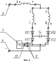
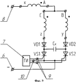
Изобретение поясняется чертежами, где на фиг.1 приведен общий вид электропривода колебательного движения, на фиг.2 - начальное положение ротора электродвигателя при подаче напряжения на фазную статорную обмотку "А-х", на фиг.3, 6 и 9 - принципиальные схемы электропривода при различных вариантах схем включения фазных статорных обмоток, на фиг.4, 5, 7 и 8 - сечения электродвигателя электропривода колебательного движения в режиме установившихся колебаний.The invention is illustrated by drawings, in which Fig. 1 shows a general view of an oscillating electric drive, Fig. 2 shows the initial position of an electric motor rotor when voltage is applied to a phase stator winding "A-x", Figs. 3, 6 and 9 are schematic diagrams of an electric drive with various options for the inclusion of phase stator windings, Fig.4, 5, 7 and 8 are sections of an electric motor of an electric drive of oscillatory motion in the mode of steady-state oscillations.
Электропривод колебательного движения (фиг.1) содержит опору 1, в которой защемлен один конец упругого элемента 2 (например, торсион), другой конец упругого элемента 2 соединен муфтой 3 с валом ротора электродвигателя 4 с одной стороны, а с другой стороны вал ротора электродвигателя 4 может соединяться муфтой 5 с механизмом, статор электродвигателя 4 установлен на опору 1. Конструкция электропривода колебательного движения представляет собой электромеханический колебательный контур, образованный упругим элементом 2, муфтами 3 и 5, электродвигателем 4 и опорой 1. Суммарный момент инерции подвижных частей электропривода JΣ и коэффициент жесткости С упругого элемента 2 обеспечивают собственную частоту колебаний в электроприводе ![]()
![]()
Явнополюсный ротор электродвигателя после подачи постоянного напряжения на обмотку "А-х", выполняющую функцию обмотки возбуждения, устанавливается относительно статора в начальное положение (фиг.2), при котором продольная ось симметрии ротора совпадает с продольной осью симметрии электромагнитного поля, образованного обмоткой возбуждения "А-х". После установки в начальное положение ротор жестко фиксируется муфтой с упругим элементом.The open-pole rotor of the electric motor after applying a constant voltage to the "A-x" winding, which performs the function of the field winding, is installed relative to the stator to the initial position (figure 2), in which the longitudinal axis of symmetry of the rotor coincides with the longitudinal axis of symmetry of the electromagnetic field formed by the field winding " Oh". After installation in the initial position, the rotor is rigidly fixed by a coupling with an elastic element.
На принципиальной схеме электропривода колебательного движения (фиг.3) представлены фазные статорные обмотки трехфазного электродвигателя ("А-х", "В-у" и "C-z"), включенные следующим образом. Обмотка "А-х" подключается началом обмотки "А" к положительному полюсу 8 источника питания постоянного тока (источник питания с трехфазным мостовым выпрямителем не показан) и концом обмотки "х" соединяется с началом обмоток "С" и "В" фазных статорных обмоток "C-z" и "В-у", выполняющих функцию рабочих обмоток соответственно. Токи через рабочие обмотки "C-z" и "В-у" должны протекать только в одном направлении, а также с целью обеспечения надежной искусственной коммутации в оба плеча схемы управления устанавливаются отсекающие диоды VD1 и VD2, анод диода VD1 соединен с концом обмотки "z", а анод диода VD2 с концом обмотки "у". Катод диода VD1 первого плеча схемы соединен с коммутирующим конденсатором Ск и анодом тиристора VS1. Анод тиристора VS2 второго плеча схемы соединяется с коммутирующим конденсатором Ск и катодом диода VD2. Соединенные катоды тиристоров VS1 и VS2 подключены к отрицательному полюсу 6 источника питания и общему выходу 10 генератора импульсов 7, сигнальные выходы 9 которого соединены с управляющими электродам тиристоров VS1 и VS2.On the schematic diagram of the electric drive of the oscillatory motion (figure 3) presents the phase stator windings of a three-phase electric motor ("A-x", "B-y" and "Cz"), included as follows. The winding "A-x" is connected by the beginning of the winding "A" to the
В режиме установившихся колебаний при подаче короткого импульса от генератора импульсов 7 на управляющий электрод тиристора VS1 (фиг.3) тиристор открывается. Через обмотку возбуждения "А-х", рабочую обмотку "C-z", диод VD1 и тиристор VS1 начинает протекать ток. Одновременно ток также протекает через обмотку "В-у" и коммутирующий конденсатор Ск, заряжая его. Время заряда коммутирующего конденсатора Ск на порядок меньше времени полупериода колебаний. Под действием электромагнитного момента ротор начинает движение против часовой стрелки из положения (фиг.4), при котором ось симметрии ротора d-d совпадает с осью потокосцепления статора O2-O2 предыдущего шага колебаний, в положение, при котором ось симметрии ротора d-d совпадет с осью потокосцепления статора O1-O1. При подаче следующего короткого импульса от генератора импульсов 7 на управляющий электрод тиристора VS2, последний открывается. Коммутирующий конденсатор Ск начинает разряжаться через контур Cк-VS2-VS1-CK, закрывая тиристор VS1. Ток начинает протекать через обмотку возбуждения "А-х", рабочую обмотку "В-у", диод VD2 и тиристор VS2. Также ток протекает через обмотку "C-z", перезаряжая коммутирующий конденсатор Ск. Под действием электромагнитного момента ротор поворачивается по часовой стрелке в положение (фиг.5), при котором ось симметрии ротора d-d совпадет с осью потокосцепления статора O2-O2. Последующий короткий импульс от генератора импульсов 7 на управляющий электрод тиристора VS1, открывает его, одновременно конденсатор Ск через контур Ск-VS1-VS2-Ск разряжается, запирая тиристор VS2. Ротор из положения O2-O2 переходит в O1-O1. Далее циклы повторяются. При описанной выше схеме включения обмоток в электроприводе колебательного движения ротор электродвигателя будет совершать колебания с размахом 120 градусов.In the mode of steady-state oscillations when a short pulse is supplied from the
Изобретение позволяет получить колебания ротора с размахом 60 (амплитудой 30) геометрических градусов (фиг.7 и 8). В электрической части электропривода колебательного движения для этой цели необходимо переподключить начало и конец рабочей фазной статорной обмотки "C-z", а также начало и конец рабочей фазной статорной обмотки "В-у" (фиг.6) или переподключить начало и конец обмотки возбуждения "А-х" (фиг.9).The invention allows to obtain oscillations of the rotor with a range of 60 (amplitude 30) geometric degrees (Fig.7 and 8). For this purpose, in the electrical part of the electric drive of oscillatory motion, it is necessary to reconnect the beginning and end of the working phase stator winding "Cz", as well as the beginning and end of the working phase stator winding "B-y" (Fig.6) or reconnect the beginning and end of the field winding "A x "(Fig.9).
Использование изобретения позволит получить колебательное движение ротора электродвигателя относительно начального положения с амплитудой от 0 до 30 или от 0 до 60 и размахом, соответственно, от 0 до 60 или от 0 до 120 геометрических градусов в зависимости от схемы включения обмоток, регулировать амплитуду колебаний и величину электромагнитного момента изменением величины напряжения постоянного тока источника питания, реализовать в разомкнутой системе управления электроприводом колебательного движения резонансный (энергетически выгодный) режим работы при задании частоты следования импульсов от генератора импульсов, совпадающей с собственной частотой колебаний электропривода, повысить эффективность электропривода.Using the invention will allow to obtain the oscillatory movement of the rotor of the electric motor relative to the initial position with an amplitude of from 0 to 30 or from 0 to 60 and a span, respectively, from 0 to 60 or from 0 to 120 geometric degrees, depending on the switching circuit of the windings, to regulate the amplitude of oscillations and the magnitude electromagnetic moment by changing the DC voltage of the power source, to implement resonant (energetically advantageous in the open-loop control system of the electric drive of oscillatory motion) ) the mode of operation when setting the pulse repetition rate from the pulse generator, which coincides with the natural frequency of the electric drive, increase the efficiency of the electric drive.
Claims (1)
Priority Applications (1)
| Application Number | Priority Date | Filing Date | Title |
|---|---|---|---|
| RU2009112967/09A RU2401503C1 (en) | 2009-04-06 | 2009-04-06 | Electric drive with vibrating motion |
Applications Claiming Priority (1)
| Application Number | Priority Date | Filing Date | Title |
|---|---|---|---|
| RU2009112967/09A RU2401503C1 (en) | 2009-04-06 | 2009-04-06 | Electric drive with vibrating motion |
Publications (1)
| Publication Number | Publication Date |
|---|---|
| RU2401503C1 true RU2401503C1 (en) | 2010-10-10 |
Family
ID=44024934
Family Applications (1)
| Application Number | Title | Priority Date | Filing Date |
|---|---|---|---|
| RU2009112967/09A RU2401503C1 (en) | 2009-04-06 | 2009-04-06 | Electric drive with vibrating motion |
Country Status (1)
| Country | Link |
|---|---|
| RU (1) | RU2401503C1 (en) |
Cited By (1)
| Publication number | Priority date | Publication date | Assignee | Title |
|---|---|---|---|---|
| RU2629946C1 (en) * | 2016-03-11 | 2017-09-05 | Федеральное государственное автономное образовательное учреждение высшего образования "Национальный исследовательский Томский политехнический университет" | Ventile electric drive with vibrating motion |
Citations (5)
| Publication number | Priority date | Publication date | Assignee | Title |
|---|---|---|---|---|
| SU1631689A1 (en) * | 1989-02-13 | 1991-02-28 | Гомельский политехнический институт | Method for control of oscillatory electric drive with asynchrounous motor |
| SU1741249A2 (en) * | 1990-04-09 | 1992-06-15 | Томский политехнический институт им.С.М.Кирова | Electric motor drive of oscillatory motion |
| RU2006173C1 (en) * | 1992-08-08 | 1994-01-15 | Анатолий Иванович Копейкин | Vibratory electric drive |
| RU2028026C1 (en) * | 1991-01-18 | 1995-01-27 | Томский политехнический университет | Electric motor drive of oscillatory motion |
| EP1298788A1 (en) * | 2001-09-28 | 2003-04-02 | Valeo Equipements Electriques Moteur | Rotating electrical machine with two power sources and commutation process |
-
2009
- 2009-04-06 RU RU2009112967/09A patent/RU2401503C1/en not_active IP Right Cessation
Patent Citations (5)
| Publication number | Priority date | Publication date | Assignee | Title |
|---|---|---|---|---|
| SU1631689A1 (en) * | 1989-02-13 | 1991-02-28 | Гомельский политехнический институт | Method for control of oscillatory electric drive with asynchrounous motor |
| SU1741249A2 (en) * | 1990-04-09 | 1992-06-15 | Томский политехнический институт им.С.М.Кирова | Electric motor drive of oscillatory motion |
| RU2028026C1 (en) * | 1991-01-18 | 1995-01-27 | Томский политехнический университет | Electric motor drive of oscillatory motion |
| RU2006173C1 (en) * | 1992-08-08 | 1994-01-15 | Анатолий Иванович Копейкин | Vibratory electric drive |
| EP1298788A1 (en) * | 2001-09-28 | 2003-04-02 | Valeo Equipements Electriques Moteur | Rotating electrical machine with two power sources and commutation process |
Cited By (1)
| Publication number | Priority date | Publication date | Assignee | Title |
|---|---|---|---|---|
| RU2629946C1 (en) * | 2016-03-11 | 2017-09-05 | Федеральное государственное автономное образовательное учреждение высшего образования "Национальный исследовательский Томский политехнический университет" | Ventile electric drive with vibrating motion |
Similar Documents
| Publication | Publication Date | Title |
|---|---|---|
| Mitcheson et al. | Tuning the resonant frequency and damping of an electromagnetic energy harvester using power electronics | |
| EP1997210B1 (en) | An electromechanical generator for, and method of, converting mechanical vibrational energy into electrical energy | |
| EP3204635B1 (en) | An electrical power generator and an electrical power generation method | |
| EP2441158B1 (en) | Electric motor for a small electric device | |
| AU2012101648A4 (en) | Method and Apparatus for Converting Between Electrical and Mechanical Energy | |
| RU2303849C1 (en) | Commutatorless permanent-magnet synchronous generator | |
| EP2023468A1 (en) | Electric power generator, method for generating electric power, and motor | |
| RU2401503C1 (en) | Electric drive with vibrating motion | |
| JP2006288186A (en) | SRL generator with improved power generation efficiency at low speed | |
| RU2638319C2 (en) | System with first and second electric motors for drive of its member | |
| KR101047759B1 (en) | DC rectifier motor | |
| KR20200014600A (en) | Bidirectional direct current generator and Hybrid generator capable of bidirectional magnetic flux control using therof | |
| RU2366072C1 (en) | Device to stabilise ac contactless generator voltage | |
| KR200242142Y1 (en) | DC Motor-Generator | |
| RU2629946C1 (en) | Ventile electric drive with vibrating motion | |
| Kovalchuk et al. | Simulation Model of a Dynamically Counterbalanced Drilling String with a Sensorless Control System for Controlling an Autoresonant AC Electric Drive | |
| KR101684024B1 (en) | Antiphase motion based energy harvester | |
| RU144223U1 (en) | MAGNETO ELECTRIC MACHINE | |
| RU2414790C1 (en) | Synchronous electric machine with modulated magnetomotive force of armature | |
| WO2010036149A1 (en) | Electromechanical vibration generator and a method for operating said generator in a forced-oscillation mode | |
| RU2440660C2 (en) | Exciter of mechanical oscillations | |
| RU124082U1 (en) | Brushless DC Motor | |
| AU2013100795B4 (en) | Method and Apparatus for Converting Between Electrical and Mechanical Energy | |
| CN108448754A (en) | Double structure switching magnetic-resistance direct current generator | |
| KR101739873B1 (en) | Power generation device using halbach array |
Legal Events
| Date | Code | Title | Description |
|---|---|---|---|
| MM4A | The patent is invalid due to non-payment of fees |
Effective date: 20110407 |