RU2397694C2 - Automated method for determining existence of heart contractions - Google Patents
Automated method for determining existence of heart contractions Download PDFInfo
- Publication number
- RU2397694C2 RU2397694C2 RU2005131958/14A RU2005131958A RU2397694C2 RU 2397694 C2 RU2397694 C2 RU 2397694C2 RU 2005131958/14 A RU2005131958/14 A RU 2005131958/14A RU 2005131958 A RU2005131958 A RU 2005131958A RU 2397694 C2 RU2397694 C2 RU 2397694C2
- Authority
- RU
- Russia
- Prior art keywords
- point
- state
- threshold value
- interval
- value
- Prior art date
Links
Images


Classifications
-
- G—PHYSICS
- G06—COMPUTING; CALCULATING OR COUNTING
- G06F—ELECTRIC DIGITAL DATA PROCESSING
- G06F17/00—Digital computing or data processing equipment or methods, specially adapted for specific functions
-
- A—HUMAN NECESSITIES
- A61—MEDICAL OR VETERINARY SCIENCE; HYGIENE
- A61B—DIAGNOSIS; SURGERY; IDENTIFICATION
- A61B5/00—Measuring for diagnostic purposes; Identification of persons
- A61B5/02—Detecting, measuring or recording pulse, heart rate, blood pressure or blood flow; Combined pulse/heart-rate/blood pressure determination; Evaluating a cardiovascular condition not otherwise provided for, e.g. using combinations of techniques provided for in this group with electrocardiography or electroauscultation; Heart catheters for measuring blood pressure
- A61B5/024—Detecting, measuring or recording pulse rate or heart rate
- A61B5/0255—Recording instruments specially adapted therefor
-
- A—HUMAN NECESSITIES
- A61—MEDICAL OR VETERINARY SCIENCE; HYGIENE
- A61B—DIAGNOSIS; SURGERY; IDENTIFICATION
- A61B5/00—Measuring for diagnostic purposes; Identification of persons
- A61B5/02—Detecting, measuring or recording pulse, heart rate, blood pressure or blood flow; Combined pulse/heart-rate/blood pressure determination; Evaluating a cardiovascular condition not otherwise provided for, e.g. using combinations of techniques provided for in this group with electrocardiography or electroauscultation; Heart catheters for measuring blood pressure
- A61B5/021—Measuring pressure in heart or blood vessels
- A61B5/02108—Measuring pressure in heart or blood vessels from analysis of pulse wave characteristics
-
- A—HUMAN NECESSITIES
- A61—MEDICAL OR VETERINARY SCIENCE; HYGIENE
- A61B—DIAGNOSIS; SURGERY; IDENTIFICATION
- A61B5/00—Measuring for diagnostic purposes; Identification of persons
- A61B5/72—Signal processing specially adapted for physiological signals or for diagnostic purposes
- A61B5/7235—Details of waveform analysis
- A61B5/7239—Details of waveform analysis using differentiation including higher order derivatives
Abstract
Description
Настоящее изобретение касается автоматизированного способа выявления сердечного сокращения, исходя из анализа выявленной кривой давления, который легко реализуем, недорог и высоко надежен, способ является пригодным для его итеративного повторения на последующих участках сигнала давления.The present invention relates to an automated method for detecting heart beat, based on the analysis of the detected pressure curve, which is easy to implement, inexpensive and highly reliable, the method is suitable for iterative repetition in subsequent sections of the pressure signal.
Настоящее изобретение дополнительно касается инструментария, необходимого для выполнения автоматизированного способа, и устройства, его выполняющего.The present invention further relates to the tools necessary to perform the automated method, and the device that performs it.
Известно, что оценивание биологических сигналов играет главную роль в диагностике и клинике.It is known that the evaluation of biological signals plays a major role in the diagnosis and clinic.
В частности, несколько автоматизированных способов для оценивания выявленной кривой кровяного давления были разработаны в последние годы, и они были реализованы в соответствующем оборудовании.In particular, several automated methods for assessing the detected blood pressure curve have been developed in recent years, and they have been implemented in appropriate equipment.
Тем не менее, такие способы и имеющее к ним отношение оборудование имеют некоторые недостатки.However, such methods and related equipment have some drawbacks.
Во-первых, они не адаптируются ко всем возможным условиям выявления, которые изменяются в зависимости от пациента, от возможного наличия паталогий и от ситуации измерения. В качестве примера, такое оборудование не распознает сигнал электрокардиограммы, полученный во время хирургической операции на сердце.Firstly, they do not adapt to all possible detection conditions, which vary depending on the patient, on the possible presence of pathologies and on the measurement situation. By way of example, such equipment does not recognize an electrocardiogram signal received during a heart surgery.
Более того, чем более оно надежно, тем оно более сложное и, следовательно, дорогое.Moreover, the more reliable it is, the more complex and therefore expensive.
Поэтому, целью настоящего изобретения является создание автоматизированного способа для выявления сердечного сокращения, исходя из анализа выявленной кривой давления, который легко реализуем, недорог и высоконадежен. Therefore, the aim of the present invention is to provide an automated method for detecting heart beat, based on the analysis of the detected pressure curve, which is easily implemented, inexpensive and highly reliable.
Кроме того, целью настоящего изобретения является предоставить инструментарий, необходимый для выполнения автоматизированного способа, и устройство, его выполняющее.In addition, the aim of the present invention is to provide the tools necessary to perform an automated method, and a device that performs it.
Особым объектом настоящего изобретения является автоматизированный способ для выявления сердечного сокращения на основе дискретизированного сигнала кровяного давления, имеющего начальную точку Pstart, отличающийся тем, что работает в соответствии с конечным автоматом, содержащим:A particular object of the present invention is an automated method for detecting heart beat based on a sampled blood pressure signal having a starting point Pstart, characterized in that it operates in accordance with a state machine containing:
А. первое состояние (1), в котором способ отыскивает:A. first state (1), in which the method searches for:
- абсолютное минимальное значение Pmin давления посредством просмотра значений давления, заключенных в пределах первого интервала времени, не выходящего за пределы интервала, продолжающегося от начальной точки Pstart до точки, удаленной от определенного минимального значения Pmin на первое временное пороговое значение DTMIN_SYS, - the absolute minimum pressure Pmin by viewing pressure values within the first time interval that does not go beyond the interval lasting from the starting point Pstart to a point remote from the determined minimum Pmin value by the first temporary threshold value DTMIN_SYS,
- абсолютное максимальное значение Pmax давления посредством просмотра значений давления, заключенных в пределах второго интервала времени, не выходящего за пределы интервала, продолжающегося от начальной точки Pstart до точки, удаленной от определенного минимального значения Pmin на второе временное пороговое значение DTMAX_SYS, и- the absolute maximum pressure value Pmax by viewing pressure values enclosed within a second time interval that does not go beyond an interval extending from a starting point Pstart to a point remote from a certain minimum Pmin value by a second temporary threshold value DTMAX_SYS, and
- максимальное значение Y1max_postdia первой производной сигнала давления, заключенное в пределах третьего временного порогового значения, не выходящего за пределы интервала, продолжающегося от начальной точки Pstart до точки, удаленной от определенного минимального значения Pmin на период, равный второму временному пороговому значению DTMAX_SYS,- the maximum value Y1max_postdia of the first derivative of the pressure signal, enclosed within the third temporary threshold value that does not go beyond the interval lasting from the starting point Pstart to a point remote from a certain minimum value Pmin for a period equal to the second temporary threshold value DTMAX_SYS,
способ принимает точку Pmin в качестве диастолической точки Pdia и точку Pmax в качестве систолической точки Psys и переходит в следующее второе состояние (2);the method takes the Pmin point as the diastolic point Pdia and the Pmax point as the systolic point Psys and switches to the next second state (2);
В. второе состояние (2), в котором способ отыскивает точку Pinflection перегиба сигнала давления, следующую за систолической точкой Psys в пятом интервале времени, не выходящем за пределы интервала, начинающегося от систолической точки Psys и с длительностью, равной третьему временному пороговому значению DTMAX_MINY1_SYS, способ затем переходит в следующее третье состояние (3);B. the second state (2), in which the method searches for the Pinflection point of the inflection of the pressure signal following the systolic point Psys in the fifth time interval that does not go beyond the interval starting from the systolic point Psys and with a duration equal to the third temporary threshold value DTMAX_MINY1_SYS, the method then proceeds to the next third state (3);
С. третье состояние (3), в котором способ проверяет, в шестом интервале времени, не выходящем за пределы интервала, начинающегося от точки Pinflection перегиба и с длительностью, равной четвертому временному пороговому значению DTMAX_SYS2Y1DIC, представляет ли сигнал давления вершину кривой с направленной вниз вогнутостью, так что:C. the third state (3), in which the method checks, in a sixth time interval that does not go beyond the interval starting from the inflection pinflection point and with a duration equal to the fourth temporary threshold value DTMAX_SYS2Y1DIC, whether the pressure signal represents the top of the curve with a downward concavity , so that:
- если результат проверки является положительным, способ отыскивает в седьмом интервале времени, не выходящем за пределы интервала, начинающегося от точки Pinflection перегиба и с длительностью, равной четвертому временному пороговому значению DTMAX_SYS2Y1DIC, первый относительный минимум кривой давления, и он принимает последний в качестве дикротической точки Pdic, тогда как- if the test result is positive, the method searches for the first relative minimum of the pressure curve in the seventh time interval that does not go beyond the interval starting from the inflection point Pinflection and with a duration equal to the fourth temporary threshold value DTMAX_SYS2Y1DIC, and it takes the latter as a dicrotic point Pdic whereas
- если результат проверки является отрицательным, способ отыскивает в упомянутом седьмом интервале времени момент времени, в который вторая производная сигнала давления принимает максимальное значение Y2max_postinflection, и он принимает соответствующую точку сигнала давления в качестве дикротической точки Pdic,- if the test result is negative, the method searches in the said seventh time interval for a point in time at which the second derivative of the pressure signal takes the maximum value Y2max_postinflection, and it takes the corresponding point of the pressure signal as the dicrotic point Pdic,
затем способ переходит в следующее четвертое состояние (4);then the method proceeds to the next fourth state (4);
D. четвертое состояние (4), в котором способ отыскивает максимальное значение Y1max_postdic первой производной сигнала давления в восьмом интервале, не выходящем за пределы интервала, начинающегося от дикротической точки Pdic и с длительностью, равной пятому временному пороговому значению DPOSTDIC, способ проверяет, что максимальное значение Y1max_postdia, определенное в первом состоянии (1), является не меньшим, чем значение Y1max_postdiс, так что:D. the fourth state (4), in which the method searches for the maximum value Y1max_postdic of the first derivative of the pressure signal in the eighth interval that does not go beyond the interval starting from the dicrotic point Pdic and with a duration equal to the fifth temporary threshold value DPOSTDIC, the method verifies that the maximum the value Y1max_postdia defined in the first state (1) is not less than the value Y1max_postdiс, so that:
- если результат проверки является отрицательным, способ возвращается в первое состояние (1), принимая в качестве новой начальной точки Pstart точку, следующую за диастолической точкой Pdia и не следующую за дикротической точкой Pdic, тогда как- if the test result is negative, the method returns to the first state (1), taking as the new starting point Pstart the point following the diastolic point Pdia and not following the dicrotic point Pdic, whereas
- если результат проверки является положительным, способ переходит в конечное состояние (7); и- if the test result is positive, the method goes into the final state (7); and
E. конечное состояние (7), в котором способ способен выдавать диастолическую точку Pdia, систолическую точку Psys и дикротическую точку Pdic.E. final state (7), in which the method is capable of delivering a diastolic point Pdia, a systolic point Psys and a dicrotic point Pdic.
Более того, согласно изобретению в первом состоянии способ может также отыскивать:Moreover, according to the invention in a first state, the method can also search for:
- максимальное значение Y2max_diatosys второй производной сигнала давления, заключенного в пределах четвертого интервала времени, не выходящего за пределы интервала, продолжающегося от начальной точки Pstart до точки, удаленной от определенного минимального значения Pmin на период, равный второму временному пороговому значению DTMAX_SYS,- the maximum value Y2max_diatosys of the second derivative of the pressure signal enclosed within the fourth time interval that does not go beyond the interval lasting from the starting point Pstart to a point remote from a certain minimum value Pmin for a period equal to the second temporary threshold value DTMAX_SYS,
с тем чтобы в четвертом состоянии способ также мог отыскивать максимальное значение Y2max_postdic второй производной сигнала давления в пределах восьмого интервала, способ также проверяет, что максимальное значение Y2max_diatosys, определенное в первом состоянии (1), является не меньшим, чем значение Y2max_postdic, так что:so that in the fourth state, the method can also find the maximum value Y2max_postdic of the second derivative of the pressure signal within the eighth interval, the method also checks that the maximum value Y2max_diatosys determined in the first state (1) is not less than the value Y2max_postdic, so that:
- если результат проверки является отрицательным, способ возвращается в первое состояние (1), принимая в качестве новой начальной точки Pstart точку, следующую за диастолической точкой Pdia и не следующую за дикротической точкой Pdic, тогда как- if the test result is negative, the method returns to the first state (1), taking as the new starting point Pstart the point following the diastolic point Pdia and not following the dicrotic point Pdic, whereas
- если результат проверки является положительным, способ переходит в конечное состояние (7).- if the test result is positive, the method goes into the final state (7).
Всегда, согласно изобретению, в первом состоянии (1) принятие точек Pmin и Pmax в качестве диастолической Pdia и систолической Psys точек соответственно может зависеть от результата проверки того, что точка Pmin предшествует точке Pmax, так что:According to the invention, always in the first state (1), the acceptance of the Pmin and Pmax points as diastolic Pdia and systolic Psys points, respectively, may depend on the result of checking that the Pmin point precedes the Pmax point, so that:
- если результат проверки является отрицательным, способ возвращается к выполнению всех операций первого состояния, принимая в качестве новой начальной точки Pstart точку, не предшествующую Pmin, тогда как- if the result of the check is negative, the method returns to performing all operations of the first state, taking as a new starting point Pstart a point not preceding Pmin, whereas
- если результат проверки является положительным, точка Pmin принимается в качестве диастолической точки Pdia и точка Pmax принимается в качестве систолической точки Psys, и способ переходит к следующему второму состоянию. - if the test result is positive, the point Pmin is taken as the diastolic point Pdia and the point Pmax is taken as the systolic point Psys, and the method proceeds to the next second state.
К тому же, согласно изобретению, конечный автомат, в соответствии с которым оно работает, может содержать пятое состояние, способ переходит из четвертого состояния в конечное состояние посредством предварительного перехода в пятое состояние, в котором способ определяет точку P3 сигнала давления, соответствующую моменту времени t3, в котором вторая производная сигнала давления принимает абсолютное минимальное значение Y2min_systodic в пределах девятого интервала, не выходящего за пределы интервала, продолжающегося от систолической точки Psys до дикротической точки Pdic, способ затем переходит в конечное состояние, в котором он способен выдавать точку P3.Moreover, according to the invention, the state machine according to which it operates may comprise a fifth state, the method transitions from the fourth state to the final state by first transitioning to the fifth state, in which the method determines a pressure signal point P3 corresponding to time t3 , in which the second derivative of the pressure signal takes the absolute minimum value Y2min_systodic within the ninth interval, not going beyond the interval continuing from the systolic point Psys to ikroticheskoy point Pdic, the method then passes to the final state in which it is capable of delivering point P3.
Предпочтительно, согласно изобретению упомянутый девятый интервал продолжается от момента времени, который является средним в пределах интервала, заключенного между систолической точкой Psys и дикротической точкой Pdic Preferably, according to the invention, said ninth interval extends from a point in time that is average within the interval between the systolic point Psys and the dicrotic point Pdic
tsys+(tdic-tsys)/2tsys + (tdic-tsys) / 2
до момента времени дикротической точки Pdicup to the time point of the dicrotic point Pdic
tdic,tdic
где tsys - момент времени, соответствующий систолической точке Psys, и tdic - момент времени, соответствующий дикротической точке Pdic.where tsys is the point in time corresponding to the systolic point Psys, and tdic is the point in time corresponding to the dicrotic point Pdic.
Более того, согласно изобретению в четвертом состоянии способ может проверять, был ли обнаружен сигнал давления в аорте, так что:Moreover, according to the invention, in a fourth state, the method can check whether a pressure signal in the aorta has been detected, so that:
- если результат проверки является положительным, способ переходит в конечное состояние, тогда как- if the result of the test is positive, the method goes into the final state, whereas
- если результат проверки является отрицательным, способ переходит в пятое состояние.- if the result of the check is negative, the method goes into the fifth state.
В частности, такая проверка может происходить на основе заданной величины, касающейся места выявления сигнала, заданного оператором в качестве входных данных. Преимущественно, такая входная заданная величина может устанавливать значение соответствующего регистра или флага, по которому способ может точно проверить значение в четвертом состоянии.In particular, such a check can take place on the basis of a predetermined value regarding the place of detection of the signal specified by the operator as input. Advantageously, such an input predetermined value can set the value of the corresponding register or flag by which the method can accurately check the value in the fourth state.
Всегда, согласно изобретению конечный автомат, в соответствии с которым оно работает, может содержать шестое состояние, в которое способ переходит в случае, когда в третьем состоянии подтвердилось, что сигнал давления представляет вершину кривой с направленной вниз вогнутостью в пределах шестого интервала времени, способ переходит в шестое состояние после четвертого состояния перед переходом в конечное состояние, в шестом состоянии способ отыскивает в упомянутом шестом интервале времени точку Р4 относительного максимума после дикротической точки Pdic, то есть верхнюю точку вершины кривой, способ затем переходит в конечное состояние, в котором он способен выдавать точку P4.Always, according to the invention, the state machine in accordance with which it operates may contain a sixth state, in which the method goes into the case when in the third state it was confirmed that the pressure signal represents the top of the curve with downward concavity within the sixth time interval, the method goes over in the sixth state after the fourth state before transitioning to the final state, in the sixth state, the method searches for the relative maximum point P4 after dicrotism in the sixth time interval At the point Pdic, that is, the top point of the curve peak, the method then goes to the final state in which it is able to give out point P4.
К тому же, согласно изобретению в шестом состоянии способ также может отыскивать точку Pend относительного минимума сигнала давления в пределах десятого интервала, не выходящего за пределы интервала, продолжающегося от дикротической точки Pdic до точки Ptermination, удаленной от дикротической точки Pdic на шестое временное пороговое значение DENDPOSTDIC, в конечном состоянии способ является способным выдавать точку Pend в случае, когда она была определена в шестом состоянии.Moreover, according to the invention in the sixth state, the method can also search for the Pend point of the relative minimum of the pressure signal within the tenth interval that does not go beyond the interval extending from the dicrotic point Pdic to the Ptermination point remote from the dicrotic point Pdic by the sixth temporary threshold value DENDPOSTDIC , in the final state, the method is capable of issuing a Pend point in the case when it was determined in the sixth state.
Предпочтительно, согласно изобретению способ отыскивает точку Pend после того, как обладает определенной точкой Р4, и упомянутый десятый интервал продолжается от точки Р4 до точки Ptermination.Preferably, according to the invention, the method searches for the Pend point after it has the determined P4 point, and said tenth interval extends from the P4 point to the Ptermination point.
Всегда предпочтительно, согласно изобретению шестое временное пороговое значение DENDPOSTDIC не больше, чем 150 миллисекунд.It is always preferable, according to the invention, the sixth temporary threshold value DENDPOSTDIC is not more than 150 milliseconds.
Более того, согласно изобретению способ может прибывать в шестое состояние, исходя из пятого состояния.Moreover, according to the invention, the method can arrive in the sixth state based on the fifth state.
Неизменно, согласно изобретению в первом состоянии способ может отыскивать первую точку Pdec, следующую за начальной точкой Pstart, принадлежащей фазе убывания сигнала давления, первый интервал времени может продолжаться от первой точки Pdec убывания до точки, удаленной от определенного минимального значения Pmin на первое временное пороговое значение DTMIN_SYS, а второй интервал времени может продолжаться от первой точки Pdec убывания до точки, удаленной от определенного минимального значения Pmin на второе временное пороговое значение DTMAX_SYS.Invariably, according to the invention, in the first state, the method can search for the first point Pdec following the starting point Pstart belonging to the decreasing phase of the pressure signal, the first time interval can continue from the first decreasing point Pdec to a point remote from the determined minimum value Pmin by the first temporary threshold value DTMIN_SYS, and the second time interval may extend from the first decrease point Pdec to a point remote from the determined minimum Pmin value by the second temporary threshold value DTMAX_SYS.
К тому же, согласно изобретению третий и четвертый интервалы времени могут продолжаться от первой точки Pdec убывания до точки, удаленной от определенного минимального значения Pmin на второе временное пороговое значение DTMAX_SYS.Furthermore, according to the invention, the third and fourth time intervals can extend from the first decrease point Pdec to a point remote from the determined minimum value Pmin by the second temporary threshold value DTMAX_SYS.
Более того, согласно изобретению третий и четвертый интервалы времени могут продолжаться от определенного минимального значения Pmin до точки, удаленной от определенного минимального значения Pmin на второе временное пороговое значение DTMAX_SYS.Moreover, according to the invention, the third and fourth time intervals can extend from a certain minimum Pmin value to a point remote from a certain minimum Pmin value by a second temporary threshold value DTMAX_SYS.
В качестве альтернативы, согласно изобретению третий и четвертый интервалы времени могут продолжаться от определенного минимального значения Pmin до определенного максимального значения Pmax.Alternatively, according to the invention, the third and fourth time intervals may extend from a certain minimum value of Pmin to a certain maximum value of Pmax.
Неизменно, согласно изобретению во втором состоянии способ может отыскивать точку Pinflection посредством поиска абсолютного минимального значения Y1min_postsys первой производной сигнала давления в пределах пятого интервала времени, принимая точку сигнала давления, в которой его первая производная принимает абсолютное минимальное значение Y1min_postsys, в качестве точки Pinflection перегиба.Invariably, according to the invention, in the second state, the method can search for the Pinflection point by searching for the absolute minimum value Y1min_postsys of the first derivative of the pressure signal within the fifth time interval, taking the point of the pressure signal at which its first derivative takes the absolute minimum value Y1min_postsys as the inflection point Pinflection.
К тому же, согласно изобретению в третьем состоянии способ может проверять в шестом интервале времени, представляет ли сигнал давления вершину кривой с направленной вниз вогнутостью, посредством поиска абсолютного максимального значения Y1max_postsys первой производной сигнала давления и посредством проверки, что это значение Y1max_postsys является положительным, в соответствии с чем, сигнал давления представляет упомянутую вершину кривой в случае, когда значение Y1max_postsys является положительным.Moreover, according to the invention in a third state, the method can check in the sixth time interval whether the pressure signal represents the top of the curve with a downward concavity by searching for the absolute maximum value Y1max_postsys of the first derivative of the pressure signal and by checking that this value Y1max_postsys is positive, accordingly, the pressure signal represents the aforementioned peak of the curve in the case when the value Y1max_postsys is positive.
Более того, согласно изобретению в третьем состоянии способ может отыскивать в пределах седьмого интервала времени первый относительный минимум кривой давления, посредством поиска момента времени, в который первая производная сигнала давления принимает нулевое значение в пределах упомянутого седьмого интервала времени.Moreover, according to the invention in a third state, the method can search within the seventh time interval for the first relative minimum of the pressure curve by searching for the point in time at which the first derivative of the pressure signal takes zero within the said seventh time interval.
Неизменно, согласно изобретению в четвертом состоянии поиск максимального значения Y1max_postdic первой производной и максимального значения Y2max_postdic второй производной сигнала давления в пределах восьмого интервала, и проверка, что оба значения являются не большими, чем максимальные значения Y1max_postdia и Y2max_diatosys, определенные в первом состоянии, могут быть выполнены только в случае, когда в третьем состоянии способ подтверждает, что сигнал давления представляет вершину кривой с направленной вниз вогнутостью в пределах шестого интервала времени.Invariably, according to the invention, in the fourth state, searching for the maximum value Y1max_postdic of the first derivative and the maximum value Y2max_postdic of the second derivative of the pressure signal within the eighth interval, and checking that both values are not larger than the maximum values Y1max_postdia and Y2max_diatosys determined in the first state, can be performed only in the case when in the third state the method confirms that the pressure signal represents the top of the curve with a downward concavity within the sixth time interval .
К тому же, согласно изобретению, когда способ возвращается из четвертого состояния в первое состояние, он может принять точку, непосредственно предшествующую определенной дикротической точке Pdic, в качестве новой начальной точки Pstart.Moreover, according to the invention, when the method returns from the fourth state to the first state, it can take the point immediately preceding the specific dicrotic point Pdic as a new starting point Pstart.
Предпочтительно, согласно изобретению первое временное пороговое значение DTMIN_SYS не больше, чем 200 миллисекунд, еще более предпочтительно - не больше, чем 150 миллисекунд.Preferably, according to the invention, the first temporary threshold value DTMIN_SYS is not more than 200 milliseconds, even more preferably not more than 150 milliseconds.
Неизменно предпочтительно, согласно изобретению второе временное пороговое значение DTMAX_SYS не больше, чем 380 миллисекунд, еще более предпочтительно - не больше, чем 350 миллисекунд.Invariably preferred, according to the invention, the second temporary threshold value DTMAX_SYS is not more than 380 milliseconds, even more preferably not more than 350 milliseconds.
К тому же, предпочтительно, согласно изобретению третье временное пороговое значение DTMAX_MINY1_SYS не больше, чем 250 миллисекунд, еще более предпочтительно - не больше, чем 200 миллисекунд.Furthermore, preferably, according to the invention, the third time threshold value DTMAX_MINY1_SYS is not more than 250 milliseconds, even more preferably not more than 200 milliseconds.
Неизменно предпочтительно, согласно изобретению четвертое временное пороговое значение DTMAX_SYS2Y1DIC не больше, чем 250 миллисекунд, еще более предпочтительно - не больше, чем 200 миллисекунд.Invariably preferred, according to the invention, the fourth temporary threshold value DTMAX_SYS2Y1DIC is not more than 250 milliseconds, even more preferably not more than 200 milliseconds.
К тому же, предпочтительно, согласно изобретению пятое временное пороговое значение DPOSTDIC не больше, чем 200 миллисекунд, еще более предпочтительно - не больше, чем 150 миллисекунд.Furthermore, preferably, according to the invention, the fifth temporary threshold value DPOSTDIC is not more than 200 milliseconds, even more preferably not more than 150 milliseconds.
Неизменно предпочтительно, согласно изобретению сигнал давления дискретизирован с частотой 1кГц.Consistently preferred, according to the invention, the pressure signal is sampled at a frequency of 1 kHz.
Более того, согласно изобретению из конечного состояния способ может вернуться к итеративному выполнению первого состояния посредством принятия точки, следующей за дикротической точкой Pdic, в качестве новой начальной точки Pstart.Moreover, according to the invention, from the final state, the method can return to the iterative execution of the first state by taking the point following the dicrotic point Pdic as the new starting point Pstart.
Всегда, согласно изобретению, когда способ прибывает в конечное состояние из четвертого или пятого состояния, из конечного состояния способ может вернуться к итеративному выполнению первого состояния посредством принятия точки, следующей за дикротической точкой Pdic и удаленной от нее на седьмое временное пороговое значение DNEW, в качестве новой начальной точки Pstart, предпочтительно не короче, чем 1 миллисекунда и не длиннее, чем 150 миллисекунд.Always, according to the invention, when the method arrives at the final state from the fourth or fifth state, from the final state the method can return to the iterative execution of the first state by accepting the point following the dicrotic point Pdic and removed from it by the seventh time threshold value DNEW, as A new Pstart starting point, preferably no shorter than 1 millisecond and no longer than 150 milliseconds.
К тому же, согласно изобретению, когда способ прибывает в конечное состояние из шестого состояния, в случае, когда в шестом состоянии точка Pend была определена, из конечного состояния способ может вернуться к итеративному выполнению первого состояния посредством принятия точки, следующей за дикротической точкой Pdic и предшествующей точке Pend, в качестве новой начальной точки Pstart, предпочтительно, посредством принятия точки, непосредственно предшествующей точке Pend, в качестве новой начальной точки Pstart.Moreover, according to the invention, when the method arrives at the final state from the sixth state, in the case where the Pend point has been determined in the sixth state, the method can return to the iterative execution of the first state by taking the point following the dicrotic point Pdic and the preceding Pend, as the new starting point of Pstart, preferably by accepting the point immediately preceding the Pend, as the new starting point of Pstart.
Более того, согласно изобретению, когда способ прибывает в конечное состояние из шестого состояния, в случае, когда в шестом состоянии точка Pend не была определена, из конечного состояния способ может вернуться к итеративному выполнению первого состояния посредством принятия точки, следующей за дикротической точкой Pdic и не следующей за точкой Ptermination, в качестве новой начальной точки Pstart, предпочтительно, посредством принятия точки, непосредственно предшествующей точке Ptermination, в качестве новой начальной точки Pstart.Moreover, according to the invention, when the method arrives at the final state from the sixth state, in the case when the Pend point has not been determined in the sixth state, the method can return to the iterative execution of the first state by accepting the point following the dicrotic point Pdic and not following the Ptermination point, as the new Pstart starting point, preferably by accepting the point immediately preceding the Ptermination point, as the new Pstart starting point.
Кроме того, еще особым объектом изучения этого изобретения является компьютер, содержащий средство интерфейса ввода и/или вывода, запоминающее средство и средство обработки, отличающийся тем, что он пригоден для выполнения ранее описанного автоматизированного способа для выявления сердечного сокращения.In addition, another special object of study of this invention is a computer containing input and / or output interface means, storage means and processing means, characterized in that it is suitable for executing the previously described automated method for detecting heart beat.
Дополнительно, отдельным объектом настоящего изобретения является устройство для выявления и анализа кровяного давления, содержащее компьютер и средство выявления кровяного давления, отличающееся тем, что упомянутый компьютер является только что проиллюстрированным компьютером.Additionally, a separate object of the present invention is a device for detecting and analyzing blood pressure, comprising a computer and means for detecting blood pressure, characterized in that said computer is a computer just illustrated.
Другим отдельным объектом этого изобретения является компьютерная программа, отличающаяся тем, что содержит кодовое средство, адаптированное, чтобы исполнять при выполнении на компьютере ранее описанный автоматизированный способ для выявления сердечного сокращения.Another separate object of this invention is a computer program, characterized in that it contains code means adapted to execute when executed on a computer the previously described automated method for detecting heart beat.
Дополнительным отдельным объектом этого изобретения является запоминающий носитель, читаемый компьютером, хранящий программу, отличающийся тем, что программа является только что описанной компьютерной программой.An additional separate object of this invention is a computer-readable storage medium storing a program, characterized in that the program is a computer program just described.
Настоящее изобретение далее будет описано в качестве иллюстрации, а не в качестве ограничения, согласно его предпочтительным вариантам осуществления, с точной ссылкой на фигуры приложенных чертежей, на которых:The present invention will now be described by way of illustration, and not by way of limitation, according to its preferred embodiments, with precise reference to the figures of the attached drawings, in which:
Фиг.1 показывает схематичную диаграмму конечного автомата, в соответствии с которым работает предпочтительный вариант осуществления способа согласно изобретению;Figure 1 shows a schematic diagram of a state machine, in accordance with which the preferred embodiment of the method according to the invention;
Фиг.2 показывает схематичную диаграмму первого состояния конечного автомата, показанного на фиг.1;Figure 2 shows a schematic diagram of a first state of the state machine shown in figure 1;
Фиг.3 показывает схематичную диаграмму третьего состояния конечного автомата, показанного на фиг.1;Figure 3 shows a schematic diagram of a third state of the state machine shown in figure 1;
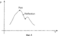
Фиг.4 показывает первую кривую давления, выявленную и проанализированную посредством предпочтительного варианта осуществления способа согласно изобретению;Figure 4 shows a first pressure curve detected and analyzed by a preferred embodiment of the method according to the invention;
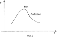
Фиг.5 показывает вторую кривую давления, выявленную и проанализированную посредством предпочтительного варианта осуществления способа согласно изобретению.Figure 5 shows a second pressure curve identified and analyzed by a preferred embodiment of the method according to the invention.
На чертежах одни и те же ссылки используются, чтобы указывать на идентичные элементы. In the drawings, the same references are used to indicate identical elements.
Изобретатели разработали способ, который предоставляет возможность сигналу давления быть выявленным во время сердечного цикла, объективность которого подтверждена тем обстоятельством, что способ является способным распознавать сигнал, полученный из кардиограммы, выполненной во время хирургической операции на сердце. Способ согласно изобретению исследует биологические сигналы, отыскивая характерные точки максимума и минимума и характерные промежуточные точки, символизирующие некоторые физиологические состояния.The inventors have developed a method that enables a pressure signal to be detected during a cardiac cycle, the objectivity of which is confirmed by the fact that the method is capable of recognizing a signal obtained from a cardiogram performed during a heart surgery. The method according to the invention examines biological signals, looking for characteristic points of maximum and minimum and characteristic intermediate points symbolizing some physiological conditions.
Более конкретно, способ согласно изобретению позволяет кривой давления, произведенного сердцем в течение своего действия, быть распознанной. Изобретатели разработали способ, принимающий в расчет то, что колебание давления сердечного сокращения принимает ряд хорошо выделяемых форм, и они определили характеристические точки кривой, рассматривая их как события, которые должны быть обнаружены посредством способа. Способ, раскрытый изобретателями, действует как конечный автомат, принимающий различные состояния при распознании характерных точек сердечного сокращения.More specifically, the method according to the invention allows the pressure curve produced by the heart during its action to be recognized. The inventors developed a method that takes into account the fact that the pressure fluctuation of the heartbeat takes a number of well distinguished forms, and they determined the characteristic points of the curve, considering them as events that should be detected by the method. The method disclosed by the inventors acts as a state machine that assumes various states when recognizing the characteristic points of a heartbeat.
В частности, для выявления сердечного сокращения в артериальной и/или венозной системе, способ согласно изобретению определяет систолическую фазу и диастолическую фазу. Систолическая фаза достигает высшей точки при достижении давлением относительного максимума, за исключением контрпульсаций, тогда как диастолическая фаза достигает высшей точки, за исключением патологических условий, при достижении давлением относительного минимума. Кроме того, способ дополнительно определяет третью точку, дикротический зубец, которая ассоциируется с сердечным сокращением. Дикротическая точка - это точка, в которой сердечный клапан закрывается, и математически она соответствует точке максимума второй производной или точке относительного минимума кривой давления, которая встречается следом за систолической точкой. Поэтому, конечный автомат сначала определяет эти три точки. Впоследствии, для того чтобы проверить, что три определенные точки действительно соответствуют сердечному сокращению, способ согласно изобретению удостоверяется в наличии ряда последующих событий с последовательностью, эквивалентной только что определенной. В положительном случае, когда такая очередность последующих событий встречается, способ распознает три предварительно определенные точки в качестве характерных точек сердечного сокращения, заканчивающегося в диастолической точке следующего сокращения.In particular, to detect cardiac contraction in the arterial and / or venous system, the method according to the invention determines the systolic phase and diastolic phase. The systolic phase reaches a peak when pressure reaches a relative maximum, with the exception of counterpulsations, while the diastolic phase reaches a peak, with the exception of pathological conditions, when the pressure reaches a relative minimum. In addition, the method further defines a third point, a dicrotic tooth, which is associated with heart beat. The dicrotic point is the point at which the heart valve closes, and mathematically it corresponds to the maximum point of the second derivative or the point of relative minimum of the pressure curve, which occurs after the systolic point. Therefore, the state machine first determines these three points. Subsequently, in order to verify that the three specific points actually correspond to the heart beat, the method according to the invention makes sure that there are a number of subsequent events with a sequence equivalent to the one just defined. In the positive case, when such a sequence of subsequent events occurs, the method recognizes three predetermined points as characteristic points of the heartbeat ending at the diastolic point of the next contraction.
Со ссылкой на фиг.1 может быть замечено, что конечный автомат, в соответствии с которым работает способ, согласно изобретению содержит семь основных состояний. With reference to FIG. 1, it can be seen that the state machine according to which the method operates according to the invention contains seven basic states.
В первом состоянии 1 способ анализирует последовательность имеющихся в распоряжении значений давления, формирующих выявленную кривую давления, с тем чтобы определить:In the first state, 1 method analyzes the sequence of available pressure values forming the identified pressure curve in order to determine:
- (относительное) минимальное значение давления, принятое в качестве диастолической точки Pdia;- (relative) minimum pressure value taken as the diastolic point of Pdia;
- (относительное) максимальное значение давления, принятое в качестве систолической точки Psys;- (relative) maximum pressure value taken as the systolic point of Psys;
- максимальное значение Y1max_postdia первой производной давления, заключенное между диастолическим значением и систолическим значением; и- the maximum value Y1max_postdia of the first derivative of pressure, concluded between the diastolic value and the systolic value; and
- максимальное значение Y2max_diatosys второй производной давления, заключенное между диастолическим значением и систолическим значением. - the maximum value Y2max_diatosys of the second derivative of pressure, concluded between the diastolic value and the systolic value.
В частности, первая производная давления пропорциональна разности между значениями в двух, следующих друг за другом моментах времени кривой давления, а вторая производная давления пропорциональна разности между значениями в двух, следующих друг за другом моментах времени первой производной давления. Более точно, коэффициент пропорциональности равен обратному значению разности между двумя, следующими друг за другом моментами времени, то есть обратному значению периода дискретизации сигнала давления. Не теряя достоверности, предпочтительный вариант осуществления способа принимает в качестве единичной разность между двумя, следующими друг за другом моментами времени, в соответствии с чем, первая производная давления равна разности между значениями в двух, следующих друг за другом моментах времени кривой давления, а вторая производная давления равна разности между значениями в двух, следующих друг за другом моментах времени первой производной.In particular, the first pressure derivative is proportional to the difference between the values at two consecutive times of the pressure curve, and the second pressure derivative is proportional to the difference between the values at two consecutive times of the first pressure derivative. More precisely, the proportionality coefficient is equal to the inverse of the difference between two consecutive times, that is, the inverse of the sampling period of the pressure signal. Without losing reliability, the preferred embodiment of the method takes as the unit difference between two successive moments of time, according to which, the first derivative of pressure is equal to the difference between the values at two successive moments of time of the pressure curve, and the second derivative pressure is equal to the difference between the values in two successive moments of time of the first derivative.
Следовательно, должно быть учтено, что дискретные точки кривой давления и связанные производные рассматриваются одна за другой во временной последовательности. Предпочтительно, выявленная кривая давления дискретизируется на частоте 1кГц, тем самым значения давления из последовательности разнесены друг от друга на 1 миллисекунду.Therefore, it should be taken into account that the discrete points of the pressure curve and the associated derivatives are considered one after another in a time sequence. Preferably, the detected pressure curve is sampled at a frequency of 1 kHz, thereby the pressure values from the sequence are spaced apart by 1 millisecond.
Со ссылкой на фиг.2 может быть замечено, что состояние 1 содержит 4 подсостояния.With reference to FIG. 2, it can be seen that
В подсостоянии 1.0 определяется первая точка Pdec, принадлежащая фазе убывания кривой давления, которая, следовательно, приводит к достижению точки относительного минимума. Предпочтительно, такое определение выполняется посредством поиска первой точки кривой давления, значение которой меньше, чем значение предшествующей точки. Как только такая точка Pdec определена, способ переходит к следующему подсостоянию 1.1.In substate 1.0, the first point Pdec is determined, which belongs to the phase of decreasing pressure curve, which, therefore, leads to reaching a point of relative minimum. Preferably, such a determination is made by searching for the first point of the pressure curve whose value is less than the value of the previous point. Once such a Pdec point is determined, the method proceeds to the next substate 1.1.
В подсостоянии 1.1 способ отыскивает точку Pmin абсолютного минимума кривой давления. В предпочтительном варианте осуществления способа, согласно изобретению, показанном на чертежах, поиск точки Pmin происходит посредством сравнения значения каждой точки P(i) кривой со значением точки Pmin_current, которая сохраняет точку, имеющую минимальное значение на предварительно исследованном участке кривой (содержащем точки от Pdec до точки P(i-1), непосредственно предшествующей рассматриваемой точке P(i)), так что Pmin_current обновляется точкой P(i), с которой она сравнивается, т.е.In substate 1.1, the method searches for the point Pmin of the absolute minimum of the pressure curve. In a preferred embodiment of the method according to the invention shown in the drawings, the search for the point Pmin occurs by comparing the value of each point P (i) of the curve with the value of the point Pmin_current, which stores the point having the minimum value in the previously studied section of the curve (containing points from Pdec to point P (i-1) immediately preceding the considered point P (i)), so that Pmin_current is updated by the point P (i) with which it is compared, i.e.
в случае, когда последняя имеет меньшее значение, т.е. в случае, когдаin the case when the latter is of lesser importance, i.e. in case when
Pmin_current может быть предварительно проинициализирована точкой Pdec, определенной в состоянии 1.0.Pmin_current can be pre-initialized with the Pdec point defined in state 1.0.
В подсостоянии 1.1 способ также отыскивает точку Pmax абсолютного максимума кривой давления. В варианте осуществления, показанном на чертежах, Pmax также отыскивается, подобно Pmin, через сравнение значения каждой точки P(i) кривой со значением точки Pmax_current, которая хранит точку, имеющую максимальное значение на предварительно исследованном участке кривой (содержащем точки от Pdec до точки P(i-1), непосредственно предшествующей рассматриваемой точке P(i)), так что Pmax_current обновляется точкой P(i), с которой она сравнивается, т.е.In substate 1.1, the method also searches for the point Pmax of the absolute maximum of the pressure curve. In the embodiment shown in the drawings, Pmax is also found, like Pmin, by comparing the value of each point P (i) of the curve with the value of the point Pmax_current, which stores the point having the maximum value in the previously studied section of the curve (containing points from Pdec to point P (i-1) immediately preceding the considered point P (i)), so that Pmax_current is updated by the point P (i) with which it is compared, i.e.
в случае, когда последняя имеет большее значение, т.е. в случае, когдаin the case when the latter is of greater importance, i.e. in case when
даже Pmax_current может быть предварительно проинициализирована точкой Pdec, определенной в состоянии 1.0.even Pmax_current can be pre-initialized with the Pdec point defined in state 1.0.
Более того, способ отыскивает максимальное значение Y1max__postdia первой производной давления, следующее за диастолической точкой. В частности, в варианте осуществления, показанном на чертежах, такое максимальное значение Y1max__postdia отыскивается через сравнение значения каждой точки Y1(i) первой производной кривой со значением точки Y1max_current, которая хранит максимальное значение первой производной на предварительно исследованном участке кривой, содержащем точки, начиная с момента времени, соответствующего точке Pmin_current, до точки Y(i-1), непосредственно предшествующей исследуемой точке Y(i), так что Y1max_current обновляется точкой Y1(i), с которой она сравнивается, т.е.Moreover, the method searches for the maximum value Y1max__postdia of the first derivative of pressure following the diastolic point. In particular, in the embodiment shown in the drawings, such a maximum value Y1max__postdia is found by comparing the value of each point Y1 (i) of the first derivative of the curve with the value of the point Y1max_current, which stores the maximum value of the first derivative in a previously examined section of the curve containing the points starting from point in time corresponding to the point Pmin_current, to the point Y (i-1) immediately preceding the studied point Y (i), so that Y1max_current is updated by the point Y1 (i) with which it is compared, i.e.
в случае, когда последняя имеет большее значение, т.е. в случае, когдаin the case when the latter is of greater importance, i.e. in case when
Y1max_current может быть предварительно проинициализирована значением первой производной кривой давления, соответствующей точке Pmin_current.Y1max_current can be pre-initialized with the value of the first derivative of the pressure curve corresponding to the point Pmin_current.
Способ покидает подсостояние 1.1 и переходит в подсостояние 1.2, когда значение точки Pmin_current не обновлено за период, более длительный, чем минимальное пороговое значение DTMIN_SYS, предпочтительно равное 200 миллисекундам, еще более предпочтительно - 150 миллисекундам. С этой целью в подсостоянии 1.1 способ устанавливает счетчик времени в нуль каждый раз, когда точка Pmin_current обновляется, и производит его приращение каждый раз, когда сравнивает ее со следующей точкой P(i) кривой давления, проверяя, превысило ли значение счетчика времени минимальное пороговое значение DTMIN_SYS. Перед переходом в подсостояние 1.2 способ принимает точку Pmin_current в качестве точки Pmin абсолютного минимума кривой давления. Другими словами, в подсостоянии 1.1 способ считает, что последняя точка Pmin_current должна быть диастолической точкой, и, следовательно, прекращает ее поиск, когда кривая давления остается над ее значением на минимальный период, соответствующий, главным образом, минимальному физиологическому промежутку времени между диастолической точкой и систолической точкой.The method leaves substate 1.1 and transitions to substate 1.2 when the value of the Pmin_current point has not been updated for a period longer than the minimum threshold DTMIN_SYS, preferably equal to 200 milliseconds, even more preferably 150 milliseconds. To this end, in substation 1.1, the method sets the time counter to zero every time the Pmin_current point is updated, and increments it every time it compares it with the next point P (i) of the pressure curve, checking whether the time counter has exceeded the minimum threshold value DTMIN_SYS. Before entering substate 1.2, the method takes the Pmin_current point as the Pmin point of the absolute minimum of the pressure curve. In other words, in substate 1.1, the method considers that the last Pmin_current point should be a diastolic point, and therefore stops its search when the pressure curve remains above its value for a minimum period, corresponding mainly to the minimum physiological time interval between the diastolic point and systolic point.
В подсостоянии 1.2 способ продолжает поиски точки Pmax абсолютного максимума кривой давления и максимального значения Y1max__postdia первой производной давления, следующего за диастолической точкой. Предпочтительно, поиски происходят аналогично тем, что происходят в подсостоянии 1.1, в соответствии с чем, в варианте осуществления способа, показанного на чертежах, они выполняются в соотвествии с формулами [3] и [4], и [5] и [6] соответственно. Такие поиски продолжаются на промежутке времени от точки Pmin, равном максимальному пороговому значению DTMAX_SYS, предпочтительно, не большему, чем 380 миллисекунд, еще более предпочтительно - не большему, чем 350 миллисекунд. С этой целью в подсостоянии 1.2, при каждом сравнении точки кривой давления с точкой Pmax_current способ осуществляет приращение счетчика времени, использованного в подсостоянии 1.1, проверяя, превысило ли значение счетчика времени максимальное пороговое значение DTMAX_SYS. Перед переходом в следующее подсостояние 1.3 способ принимает точку Pmax_current в качестве точки Pmax абсолютного максимума кривой давления и значение Y1max_current - в качестве максимального значения Y1max__postdia первой производной давления, следующего за диастолической точкой. Другими словами, в подсостоянии 1.2 способ отыскивает систолическую точку (и максимальное значение первой производной давления, следующего за диастолической точкой) на интервале кривой давления, соответствующем, главным образом, максимальному физиологическому промежутку времени между диастолической точкой и систолической точкой.In substate 1.2, the method continues to search for the point Pmax of the absolute maximum of the pressure curve and the maximum value Y1max__postdia of the first derivative of the pressure following the diastolic point. Preferably, the searches are carried out similarly to those that occur in substation 1.1, according to which, in the embodiment of the method shown in the drawings, they are performed in accordance with formulas [3] and [4], and [5] and [6] respectively . Such searches continue over a period of time from the point Pmin equal to the maximum threshold value DTMAX_SYS, preferably not more than 380 milliseconds, even more preferably not more than 350 milliseconds. To this end, in substation 1.2, each time the pressure curve point is compared with the Pmax_current point, the method increments the time counter used in substation 1.1, checking whether the time counter has exceeded the maximum threshold value DTMAX_SYS. Before moving to the next substate 1.3, the method takes the point Pmax_current as the point Pmax of the absolute maximum of the pressure curve and the value Y1max_current as the maximum value Y1max__postdia of the first derivative of the pressure following the diastolic point. In other words, in substate 1.2, the method searches for the systolic point (and the maximum value of the first derivative of the pressure following the diastolic point) on the interval of the pressure curve corresponding mainly to the maximum physiological time interval between the diastolic point and the systolic point.
Способ выполняет одновременный поиск диастолической точки и систолической точки в подсостоянии 1.1 для принятия в расчет сердечной аритмии и контрпульсации (тем самым, диастолическая и систолическая точки могут быть относительными, вместо того, чтобы быть абсолютными точками максимума и минимума кривой давления), и возможный шум, вносимый в кривую давления событиями, не соотвествующими физиологии кривой, как например, электрический шум, кашель пациента или перемещение инструмента выявления кровяного давления (например, катетера). Такой одновременный поиск, в случае сильных шумов, может дать физиологически неправильный результат, при котором точка Pmin абсолютного минимума следует за точкой Pmax абсолютного максимума. Поэтому, в подсостоянии 1.3 способ убеждается, что точка Pmin, определенная в подсостоянии 1.1, предшествует точке Pmax, определенной в подсостоянии 1.1 или 1.2.The method simultaneously searches for a diastolic point and a systolic point in substate 1.1 to take into account cardiac arrhythmias and counterpulsations (thus, the diastolic and systolic points can be relative, instead of being absolute points of the maximum and minimum pressure curve), and the possible noise, introduced into the pressure curve by events that do not correspond to the physiology of the curve, such as electrical noise, a patient’s cough, or movement of a blood pressure detection tool (such as a catheter). Such a simultaneous search, in the case of strong noise, can give a physiologically incorrect result, at which the absolute minimum point Pmin follows the absolute maximum point Pmax. Therefore, in substate 1.3, the method makes sure that the point Pmin defined in substate 1.1 precedes the point Pmax defined in substate 1.1 or 1.2.
Если результат проверки является отрицательным, способ возвращается к выполнению подсостояния 1.0, начиная с предварительно определенной точки Pmin кривой давления. Таким образом, подсостояние 1.1 будет отыскивать точку абсолютного минимума, следующую за такой же, предварительно определенной точкой.If the test result is negative, the method returns to the execution of the substate 1.0, starting from the predetermined point Pmin of the pressure curve. Thus, substate 1.1 will look for an absolute minimum point following the same predefined point.
Иначе, если проверка выдала положительный результат, точка Pmin абсолютного минимума принимается в качестве диастолической точки Pdia и точка Pmax абсолютного максимума принимается в качестве систолической точки Psys; также, способ определяет максимальное значение Y2max_diatosys второй производной давления, которое заключено между диастолической точкой и систолической точкой. Такое определение может, кроме того, быть выполнено совместно с поисками диастолической и систолической точек, посредством соответствующей модификации подсостояний 1.1 и 1.2. В заключение, способ переходит в следующее второе состояние 2. Otherwise, if the test returns a positive result, the absolute minimum point Pmin is taken as the diastolic point Pdia and the absolute maximum point Pmax is taken as the systolic point Psys; also, the method determines the maximum value Y2max_diatosys of the second derivative of the pressure, which is located between the diastolic point and the systolic point. Such a determination can, in addition, be made in conjunction with the search for diastolic and systolic points, by means of a corresponding modification of substates 1.1 and 1.2. In conclusion, the method proceeds to the next
Временные проверки, выполненные в подсостояниях 1.1 и 1.2, позволяют способу согласно изобретению принимать в расчет тот факт, что когда сердечная частота изменяется, систолическая фаза является физиологически постоянной по длительности величиной (в соответствии с чем, систолическая точка возникает в интервале, тянущемся от, примерно, 150 до, примерно, 360 миллисекунд, после диастолической точки), тогда как диастолическая фаза, наоборот, варьирует свою длительность, когда частота изменяется; следовательно, способ правильно распознает диастолическую и систолическую точки, даже в случае очень низкой сердечной частоты.Temporary checks performed in substates 1.1 and 1.2 allow the method according to the invention to take into account the fact that when the heart rate changes, the systolic phase is physiologically constant in duration (according to which, the systolic point occurs in an interval stretching from approximately 150 to about 360 milliseconds after the diastolic point), while the diastolic phase, on the contrary, varies in duration when the frequency changes; therefore, the method correctly recognizes diastolic and systolic points, even in the case of a very low heart rate.
По-прежнему делая ссылку на фиг. 1, как только диастолическая Pdia и систолическая Psys точки и значения Y1max_postdia и Y2max_diatosys определены, конечный автомат входит во второе состояние 2, в котором способ согласно изобретению отыскивает абсолютное минимальное значение Y1min_postsys первой производной давления после систолы в интервале с длительностью, равной DTMAX_MINY1_SYS, следующем за систолой; в частности, DTMAX_MINY1_SYS равен максимальной длительности физиологического интервала, в котором минимальное значение первой производной давления следует за систолической точкой, и он, предпочтительно, не длинее 250 миллисекунд, еще более предпочтительно - не длиннее 200 миллисекунд. Таким образом, способ определяет точку Pinflection перегиба, следующую за систолой кривой давления, в которой первая производная давления принимает абсолютное минимальное значение Y1min_postsys, для того чтобы различать случаи, когда кривая давления выявляется в условиях сильных шумов, в соответствии с чем форма сигнала давления может представлять небольшую вершину кривой или короткий пологий участок, непосредственно следующий за систолой, и на котором способ мог бы затем ошибочно распознать дикротическую точку. Взамен, определение абсолютного минимального значения Y1min_postsys безошибочно сдвигает поиск дикротического зубца за пределы этих маленьких вершин кривой или пологих участков, непосредственно следующих за систолой.Still referring to FIG. 1, as soon as the diastolic Pdia and systolic Psys points and Y1max_postdia and Y2max_diatosys values are determined, the state machine enters the
Впоследствии, конечный автомат входит в третье состояние 3, в котором способ согласно изобретению отыскивает дикротическую точку.Subsequently, the state machine enters the
Со ссылкой на фиг.3 может быть замечено, что состояние 3 содержит 4 подсостояния.With reference to FIG. 3, it can be seen that
В подсостоянии 3.0, в интервале времени c длительностью, равной DTMAX_SYS2Y1DIC, следующем за точкой Pinflection перегиба, определяется точка Y1max_postsys абсолютного максимума первой производной, с переходом, затем, в следующее состояние 3.1. В частности, DTMAX_SYS2Y1DIC равно максимальной длительности физиологического интервала, в котором дикротический зубец следует за точкой перегиба, и, предпочтительно, DTMAX_SYS2Y1DIC не больше 250 миллисекунд, еще более предпочтительно - не больше 200 миллисекунд.In substate 3.0, in the time interval with a duration equal to DTMAX_SYS2Y1DIC, following the inflection point Pinflection, the absolute maximum point of the first derivative Y1max_postsys is determined, with the transition, then, to the next state 3.1. In particular, DTMAX_SYS2Y1DIC is equal to the maximum duration of the physiological interval in which the dicrotic tooth follows the inflection point, and preferably, DTMAX_SYS2Y1DIC is not more than 250 milliseconds, even more preferably not more than 200 milliseconds.
В подсостоянии 3.1 способ проверяет, является ли точка Y1max_postsys, определенная в подсостоянии 3.0, положительной.In substate 3.1, the method checks if the Y1max_postsys point defined in substate 3.0 is positive.
Если результат проверки является положительным, это означает, что кривая давления представляет вершину кривой после дикротической точки, как схематично показано на фиг. 4, в силу чего, в этом случае дикротическая точка Pdic соответствует точке первого относительного минимума кривой давления, следующей за точкой Pinflection перегиба, определенной во втором состоянии 2. Поэтому, способ выполняет подсостояние 3.2, в котором определяет такую точку Pdic, посредством определения момента времени, в который первая производная кривой давления принимает нулевое значение на интервале времени, с длительностью, равной DTMAX_SYS2Y1DIC, следующем за точкой Pinflection перегиба. Способ затем переходит в следующее, четвертое состояние 4.If the test result is positive, this means that the pressure curve represents the peak of the curve after the dicrotic point, as shown schematically in FIG. 4, due to which, in this case, the dicrotic point Pdic corresponds to the point of the first relative minimum of the pressure curve following the inflection point Pinflection defined in the
Взамен, в случае, когда результат проверки в подсостоянии 3.1 был отрицательным, или точка Y1max_postsys абсолютного максимума первой производной, определенная в подсотоянии 3.0, не является положительной, кривая давления не представляет никакой вершины после дикротической точки, и последняя соответствует точке, в которой вторая производная давления принимает максимальное значение. Поэтому, способ выполняет подсостояние 3.3, в котором он определяет дикротическую точку Pdic, посредством определения момента времени, в котором вторая производная кривой давления принимает максимальное значение Y2max_postinflection на интервале времени, с длительностью, равной DTMAX_SYS2Y1DIC, следующем за точкой Pinflection перегиба. Способ затем переходит в следующее, четвертое состояние 4.Instead, in the case where the test result in substate 3.1 was negative, or the point Y1max_postsys of the absolute maximum of the first derivative, defined in substate 3.0, is not positive, the pressure curve does not represent any vertex after the dicrotic point, and the latter corresponds to the point at which the second derivative pressure takes maximum value. Therefore, the method performs substate 3.3, in which it determines the dicrotic point Pdic, by determining the point in time at which the second derivative of the pressure curve takes the maximum value Y2max_postinflection in the time interval with a duration equal to DTMAX_SYS2Y1DIC following the inflection point Pinflection. The method then proceeds to the next,
По-прежнему делая ссылку на фиг.1, конечный автомат входит в четвертое состояние 4, в котором способ согласно изобретению определяет максимальное значение Y1max_postdic первой производной и максимальное значение Y2max_postdic второй производной кривой давления, после дикротической точки Pdic, определенной в третьем состоянии 3. Такой поиск осуществляется в интервале DPOSTDIC, следующем за дикротической точкой, предпочтительно, не более длинном, чем 150 миллисекунд. Впоследствии, способ проверяет, является ли меньшим, чем только что определенное значение соответствующей производной, соответственно, Y1max_postdic и Y2max_postdic, по меньшей мере, одно из двух максимальных значений Y1max_postdia и Y2max_diatosys, принадлежащих, соответственно, первой производной и второй производной давления, следующим за диастолической точкой, и которые определены в первом состоянии 1. Такая проверка необходима, для того чтобы различить случай, в котором, когда представлены конкретные сигналы давления, имеющие вершины кривой после дикротического зубца, определенная дикротическая точка Pdic является, фактически, диастолической точкой. Это пример кривой давления, выявленной на чрезвычайно упругом сердце (таком, как сердце атлета), находящемся в напряжении, при этом, возможно проверить, что дикротическая точка имеет меньшее значение давления, чем в диастолической точке. Однако, даже в этом случае, физиологическая скорость нарастания кривой давления вдоль участка между диастолической точкой и систолической точкой больше, чем физиологический темп нарастания кривой давления после дикротической точки. Это различается посредством всего лишь сравнения максимальных значений первой и второй производных после, соответственно, точки, принятой в качестве диастолической точки, и точки, принятой в качестве дикротической точки.Still referring to FIG. 1, the state machine enters the
В этом отношении, другие варианты осуществления способа согласно изобретению выполняют в четвертом состоянии 4 определение значений Y1max_postdic и Y2max_postdic, и их сравнение со значениями Y1max_postdia и Y2max_diatosys, только в случае, когда в третьем состоянии 3 было установлено наличие вершины кривой после дикротической точки.In this regard, other embodiments of the method according to the invention in the
В случае, когда проверка дает положительный результат (то есть, по меньшей мере, одно из двух значений Y1max_postdia и Y2max_diatosys меньше, чем Y1max_postdic или Y2max_postdic соответственно), определенная диастолическая точка Pdia, систолическая точка Psys и дикротическая точка Pdic не соответствуют физиологически правильной кривой давления, и способ возвращается к выполнению подсостояния 1.0 первого состояния 1, начиная с точки, следующей за Pdia, которая была определена в качестве диастолической точки и предшествующей Pdic, определенной в качестве дикротической точки, для определения диастолической и/или систолической и/или дикротической точек, отличающихся от тех, которые были предварительно определены. Предпочтительно, способ возвращается к выполнению подсостояния 1.0 первого состояния 1, начиная с точки, непосредственно предшествующей точке Pdic, определенной в третьем состоянии 3 в качестве дикротической точки.In the case where the test yields a positive result (that is, at least one of the two values Y1max_postdia and Y2max_diatosys is less than Y1max_postdic or Y2max_postdic, respectively), the determined diastolic point Pdia, the systolic point Psys and the dicrotic point Pdic do not correspond physiologically correctly , and the method returns to performing substate 1.0 of the
В случае, когда проверка дает отрицательный результат (то есть оба значения Y1max_postdia и Y2max_diatosys больше, чем значения Y1max_postdic или Y2max_postdic соответственно), определенные точки Pdia, Psys, и Pdic являются физиологически правильными, и способ дополнительно проверяет, была ли обнаружена кривая давления в аорте.In the case where the test yields a negative result (that is, both Y1max_postdia and Y2max_diatosys are greater than Y1max_postdic or Y2max_postdic, respectively), the determined points Pdia, Psys, and Pdic are physiologically correct, and the method additionally checks if a pressure curve was detected in the aorta .
В положительном случае, способ сразу переходит в конечное состояние 7, в котором он выдает все выявленные данные в качестве характеристических данных сокращения, кривую давления которого способ исследовал, и, возможно, возвращается к выполнению первого состояния 1 для исследования следующего сокращения.In the positive case, the method immediately goes to the final state 7, in which it outputs all the detected data as characteristic data of the contraction, the pressure curve of which the method examined, and possibly returns to the
В отрицательном случае (кривая давления была обнаружена в аорте), способ переходит в пятое состояние 5, в котором он определяет точку Р3 кривой давления, соответствующую моменту времени t3, в который вторая производная кривой принимает минимальное значение Y2min_systodic по интервалу между систолической точкой и дикротической точкой. Предпочтительно, интервал продолжается от точки, являющейся средней в интервале, заключенном между систолической точкой Psys и дикротической точкой Pdic, до следующей точки Pdic. Другими словами, интервал, в котором определено значение Y2min_systodic, предпочтительно, продолжается от момента времени In the negative case (the pressure curve was detected in the aorta), the method goes into the
tsys+(tdic-tsys)/2tsys + (tdic-tsys) / 2
до момента времени until time
tdic,tdic
где tsys - момент времени, соответствующий систолической точке, а tdic - момент времени, соответствующий дикротической точке.where tsys is the point in time corresponding to the systolic point, and tdic is the point in time corresponding to the dicrotic point.
Впоследствии, в случае, когда в третьем состоянии 3 наличие вершины вдоль кривой давления не было распознано, способ переходит к выполнению конечного состояния 7; в противном случае (в третьем состоянии 3 было установлено, что кривая давления имеет вершину) способ переходит к выполнению шестого состояния 6.Subsequently, in the case when the presence of a vertex along the pressure curve was not recognized in the
В шестом состоянии 6 способ отыскивает точку Р4 относительного максимума после дикротической точки, то есть верхнюю точку вершины кривой, соответствующую моменту времени, в который первая производная кривой давления принимает неотрицательное минимальное значение в пределах интервала, следующего за дикротической точкой. В частности, поиск точки P4 выполняется в пределах интервала DPOSTDIC, следующего за дикротическим зубцом.In the
Более того, в шестом состоянии 6 способ также отыскивает точку Pend относительного минимума после дикротической точки, то есть окончание исследуемого сокращения. В частости, поиск точки Pend выполняется по интервалу, продолжающемуся от точки P4 до точки Ptermination, удаленной на DENDPOSTDIC от дикротической точки Pdic, равному максимальному физиологическому промежутку времени между дикротической точкой и следующим аномальным сокращением (экстрасистолой) или ускоренным сокращением (высокие сердечные частоты); предпочтительно, DENDPOSTDIC - не больше, чем 150 миллисекунд. В заключение, способ переходит в конечное состояние 7.Moreover, in the
Как сказано, в конечном состоянии 7 способ выдает все выявленные данные в качестве характеристических данных сокращения, кривую давления которого способ исследовал, и, возможно, возвращается к выполнению первого состояния 1 для исследования следующего сокращения. В частности, в случае, когда состояние 7 достигается из состояния 4 или состояния 5, способ возвращается к выполнению первого состояния 1, начиная с точки, следующей за дикротической точкой Pdic через интервал DNEW, который, предпочтительно, не короче, чем 1 миллисекунда и не длиннее, чем 150 миллисекунд; в случае, когда состояние 7 достигается из состояния 6, способ возвращается к выполнению подсостояния 1.0 первого состояния 1, начиная с точки, следующей за дикротической точкой Pdic и предшествующей определенной точке Pend (предпочтительно, начиная с точки, непосредственно предшествующей определенной точке Pend), или, в случае, когда точка Pend не была определена, с точки, следующей за дикротической точкой Pdic и не следующей за точкой Ptermination (предпочтительно, начиная с точки, непосредственно предшествующей определенной точке Ptermination).As said, in the final state 7, the method provides all the detected data as characteristic data of the contraction, the pressure curve of which the method examined, and possibly returns to the
Преимущества, полученные благодаря способу согласно изобретению, многочисленны. The advantages obtained by the method according to the invention are numerous.
Во-первых, способ является способным добиваться распознавания пульса из анализа кривой давления, произведенного сердцем во время его работы, достоверно разграничивая начальную и конечную точки каждого сокращения.Firstly, the method is capable of achieving pulse recognition from an analysis of the pressure curve produced by the heart during its operation, reliably distinguishing between the start and end points of each contraction.
Кроме того, способ является способным различать случаи, в которых диастолическая и систолическая точки являются относительными, а не абсолютными точками минимума и максимума, когда кривая давления также представляет другие точки минимума и максимума. Фактически, диастолическая и систолическая точки распознаются как действительные, только если при переходе от одной к другой, первая производная (а также вторая производная) кривой давления достигает своего максимума в пределах полного сокращения.In addition, the method is capable of distinguishing between cases in which the diastolic and systolic points are relative and not absolute minimum and maximum points, when the pressure curve also represents other minimum and maximum points. In fact, the diastolic and systolic points are recognized as real only if, when moving from one to the other, the first derivative (as well as the second derivative) of the pressure curve reaches its maximum within the full contraction.
Кроме того, способ определяет диастолическую, систолическую и дикротическую точки посредством исследования интервалов времени, довольно протяженных, вокруг точек максимума или минимума или перегиба.In addition, the method determines diastolic, systolic and dicrotic points by examining time intervals, quite long, around the points of maximum or minimum or inflection.
Программа определяет диастолическую, систолическую и дикротическую точки в пределах временных границ, физиологически зависящих от места, где выявляется давление. В частности, фактическое закрытие пульсации происходит после того, как были определены диастолическая, систолическая и дикротическая точки следующего сокращения.The program identifies diastolic, systolic and dicrotic points within time boundaries physiologically dependent on the place where the pressure is detected. In particular, the actual closure of the pulsation occurs after the diastolic, systolic and dicrotic points of the next contraction have been determined.
Способ согласно изобретению также позволяет, в случае очень низкой частоты, определять сокращение, несмотря на ограничения, накладываемые на время между дикротическим зубцом и диастолой, поскольку принимается во внимание тот факт, что систолическая фаза физиологически не очень изменчива по длительности, когда меняется сердечная частота, тогда как диастолическая фаза, наоборот, изменяет свою длительность, когда меняется частота.The method according to the invention also allows, in the case of a very low frequency, to determine the reduction, despite the restrictions imposed on the time between the dicrotic tooth and the diastole, since it is taken into account that the systolic phase is physiologically not very variable in duration when the heart rate changes, whereas the diastolic phase, on the contrary, changes its duration when the frequency changes.
Более того, способ согласно изобретению позволяет сигналу электрокардиограммы быть достоверно изученным.Moreover, the method according to the invention allows the signal of the electrocardiogram to be reliably studied.
Выше были описаны предпочтительные варианты осуществления и были предложены некоторые модификации этого изобретения, но должно быть понято, что специалисты в данной области техники могут создать другие варианты и изменения, не выходя от связанного объема охраны, как определено последующей формулой изобретения.The preferred embodiments have been described above and some modifications of this invention have been proposed, but it should be understood that those skilled in the art can make other variations and changes without departing from the associated scope of protection as defined by the following claims.
Claims (112)
абсолютное минимальное значение Pmin давления посредством просмотра значений давления, заключенных в пределах первого интервала времени, не выходящего за пределы интервала, продолжающегося от начальной точки Pstart до точки, удаленной от определенного минимального значения Pmin на первое временное пороговое значение DTMIN_SYS,
абсолютное максимальное значение Рmах давления, посредством просмотра значений давления, заключенных в пределах второго интервала времени, не выходящего за пределы интервала, продолжающегося от начальной точки Pstart до точки, удаленной от определенного минимального значения Pmin на второе временное пороговое значение DTMAX_SYS, и
максимальное значение Y1max-postdia первой производной сигнала давления, заключенное в пределах третьего временного интервала, не выходящего за пределы интервала, продолжающегося от начальной точки Pstart до точки, удаленной от определенного минимального значения Pmin на период, равный второму временному пороговому значению DTMAX_SYS,
способ принимает точку Pmin в качестве диастолической точки Pdia, а точку Рmах в качестве систолической точки Psys, и переходит в следующее второе состояние (2);
В. второе состояние (2), в котором способ отыскивает точку Pinflection перегиба сигнала давления, следующую за систолической точкой Psys в четвертом интервале времени, не выходящем за пределы интервала, начинающегося от систолической точки Psys и с длительностью, равной третьему временному пороговому значению DTMAX_MINY1_SYS, способ затем переходит в следующее третье состояние (3);
С. третье состояние (3), в котором способ проверяет в пятом интервале времени, не выходящем за пределы интервала, начинающегося от точки Pinflection перегиба и с длительностью, равной четвертому временному пороговому значению DTMAX_SYS2Y1DIC, при этом четвертое временное пороговое значение DTMAX_SYS2Y1DIC равно максимальной длительности физиологического интервала, в котором дикротическая точка следует за точкой перегиба, представляет ли сигнал давления вершину кривой с направленной вниз вогнутостью, так что:
если результат проверки является положительным, способ отыскивает в шестом интервале времени, не выходящем за пределы интервала, начинающегося с точки Pinflection перегиба и с длительностью, равной четвертому временному пороговому значению DTMAX_SYS2Y1DIC, момент времени, в который первая производная кривой давления принимает нулевое значение, и последний принимается в качестве дикротической точки Pdic, тогда как
если результат проверки является отрицательным, способ отыскивает в упомянутом шестом интервале времени, момент времени, в который вторая производная сигнала давления принимает максимальное значение Y2max postinflection, и имеющая отношение точка сигнала давления принимается в качестве дикротической точки Pdic, затем способ переходит в следующее четвертое состояние (4);
D. четвертое состояние (4), в котором способ отыскивает максимальное значение Y1max postdic первой производной сигнала давления в седьмом интервале, не выходящем за пределы интервала, начинающегося от дикротической точки Pdic и с длительностью, равной пятому временному пороговому значению DPOSTDIC, способ проверяет, что максимальное значение Y1max postdia, определенное в первом состоянии (1), является не меньшим, чем значение Y1max_postdic, так что:
если результат проверки является отрицательным, способ возвращается в первое состояние (1), принимая в качестве новой начальной точки Pstart точку, следующую за диастолической точкой Pdia и не следующую за дикротической точкой Pdic, тогда как
если результат проверки является положительным, способ переходит в конечное состояние (7); и
E. конечное состояние (7), в котором способ способен выдавать диастолическую точку Pdia, систолическую точку Psys и дикротическую точку Pdic.1. An automated method for detecting heart beat based on a discretized blood pressure signal having a starting point Pstart, characterized in that it operates in accordance with a state machine containing: A. first state (1), in which the method searches for:
the absolute minimum pressure Pmin by viewing pressure values enclosed within a first time interval that does not go beyond an interval extending from a starting point Pstart to a point remote from a certain minimum Pmin value by a first temporary threshold value DTMIN_SYS,
the absolute maximum pressure value Pmax by viewing pressure values enclosed within a second time interval that does not go beyond an interval extending from a starting point Pstart to a point remote from a certain minimum value Pmin by a second temporary threshold value DTMAX_SYS, and
the maximum value Y1max-postdia of the first derivative of the pressure signal, concluded within the third time interval, not going beyond the interval lasting from the starting point Pstart to a point remote from a certain minimum value Pmin for a period equal to the second temporary threshold value DTMAX_SYS,
the method takes the point Pmin as the diastolic point Pdia, and the point Pmax as the systolic point Psys, and passes to the next second state (2);
B. the second state (2), in which the method searches for the Pinflection point of the inflection of the pressure signal following the systolic point Psys in the fourth time interval that does not go beyond the interval starting from the systolic point Psys and with a duration equal to the third temporary threshold value DTMAX_MINY1_SYS, the method then proceeds to the next third state (3);
C. the third state (3), in which the method checks in the fifth time interval that does not go beyond the interval starting from the inflection point Pinflection and with a duration equal to the fourth temporary threshold value DTMAX_SYS2Y1DIC, while the fourth temporary threshold value DTMAX_SYS2Y1DIC is equal to the maximum physiological duration the interval in which the dicrotic point follows the inflection point, whether the pressure signal represents the top of the curve with a downward concavity, so that:
if the test result is positive, the method searches for a sixth time interval that does not go beyond the interval starting at the inflection pinflection point and with a duration equal to the fourth time threshold value DTMAX_SYS2Y1DIC, the point in time at which the first derivative of the pressure curve takes a zero value, and the last taken as a dicrotic point of Pdic, whereas
if the test result is negative, the method searches in the sixth time interval, the point in time at which the second derivative of the pressure signal takes the maximum value Y2max postinflection, and the related pressure signal point is taken as the dicrotic point Pdic, then the method goes to the next fourth state ( four);
D. the fourth state (4), in which the method searches for the maximum Y1max postdic value of the first derivative of the pressure signal in the seventh interval, which does not go beyond the interval starting from the dicrotic point Pdic and with a duration equal to the fifth temporary threshold value DPOSTDIC, the method checks that the maximum value Y1max postdia defined in the first state (1) is not less than the value Y1max_postdic, so that:
if the test result is negative, the method returns to the first state (1), taking as the new starting point Pstart the point following the diastolic point Pdia and not following the dicrotic point Pdic, whereas
if the test result is positive, the method goes to the final state (7); and
E. final state (7), in which the method is capable of delivering a diastolic point Pdia, a systolic point Psys and a dicrotic point Pdic.
если результат проверки является отрицательным, способ возвращается к выполнению всех операций первого состояния (1), принимая в качестве новой начальной точки Pstart точку, не предшествующую Pmin, тогда как если результат проверки является положительным, точка Pmin принимается в качестве диастолической точки Pdia и точка Рmах принимается в качестве систолической точки Psys, и способ переходит в следующее второе состояние (2).2. The method according to claim 1, characterized in that in the first state (1) the adoption of the points Pmin and Pmax as diastolic Pdia and systolic Psys points, respectively, depends on the result of checking that the Pmin point precedes the point Pmax, so that:
if the test result is negative, the method returns to performing all operations of the first state (1), taking as a new starting point Pstart a point not preceding Pmin, while if the test result is positive, the point Pmin is accepted as the diastolic point Pdia and the point Pmax is taken as the systolic point of Psys, and the method proceeds to the next second state (2).
tsys+(tdic-tsys)/2
до момента времени дикротической точки Pdic
tdic,
где tsys - момент времени, соответствующий систолической точке Psys, a
tdic - момент времени, соответствующий дикротической точке Pdic.4. The method according to claim 3, characterized in that said eighth interval continues from a point in time that occupies a middle position within the interval between the systolic point Psys and the dicrotic point Pdic
tsys + (tdic-tsys) / 2
up to the time point of the dicrotic point Pdic
tdic
where tsys is the moment of time corresponding to the systolic point Psys, a
tdic is the moment of time corresponding to the dicrotic point of Pdic.
А. первое состояние (1), в котором способ отыскивает:
абсолютное минимальное значение Pmin давления, посредством просмотра значений давления, заключенных в пределах первого интервала времени, не выходящего за пределы интервала, продолжающегося от начальной точки Pstart до точки, удаленной от определенного минимального значения Pmin на первое временное пороговое значение DTMIN_SYS,
абсолютное максимальное значение Рmах давления, посредством просмотра значений давления, заключенных в пределах второго интервала времени, не выходящего за пределы интервала, продолжающегося от начальной точки Pstart до точки, удаленной от определенного минимального значения Pmin на второе временное пороговое значение DTMAX_SYS, и
максимальное значение Y1max_postdia первой производной сигнала давления, заключенное в пределах третьего временного интервала, не выходящего за пределы интервала, продолжающегося от начальной точки Pstart до точки, удаленной от определенного минимального значения Pmin на период, равный второму временному пороговому значению DTMAX_SYS,
максимальное значение Y2max_diatosys второй производной сигнала давления, заключенное в пределах четвертого интервала времени, не выходящего за пределы интервала, продолжающегося от начальной точки Pstart до точки, удаленной от определенного минимального значения Pmin на период, равный второму временному пороговому значению DTMAX_SYS,
способ принимает точку Pmin в качестве диастолической точки Pdia, a точку Рmах в качестве систолической точки Psys, и переходит в следующее второе состояние (2);
B. второе состояние (2), в котором способ отыскивает точку Pinflection перегиба сигнала давления, следующую за систолической точкой Psys в четвертом интервале времени, не выходящем за пределы интервала, начинающегося от систолической точки Psys и с длительностью, равной третьему временному пороговому значению DTMAX_MINY1_SYS, способ затем переходит в следующее третье состояние (3);
C. третье состояние (3), в котором способ проверяет в пятом интервале времени, не выходящем за пределы интервала, начинающегося от точки Pinflection перегиба и с длительностью, равной четвертому временному пороговому значению DTMAX_SYS2Y1DIC, при этом четвертое временное пороговое значение DTMAX_SYS2Y1DIC равно максимальной длительности физиологического интервала, в котором дикротическая точка следует за точкой перегиба, представляет ли сигнал давления вершину кривой с направленной вниз вогнутостью, так что:
если результат проверки является положительным, способ отыскивает в шестом интервале времени, не выходящем за пределы интервала, начинающегося с точки Pinflection перегиба и с длительностью, равной четвертому временному пороговому значению DTMAX_SYS2Y1DIC, момент времени, в который первая производная кривой давления принимает нулевое значение, и последний принимается в качестве дикротической точки Pdic, тогда как
если результат проверки является отрицательным, способ отыскивает в упомянутом шестом интервале времени момент времени, в который вторая производная сигнала давления принимает максимальное значение Y2max_postinflection, и имеющая отношение точка сигнала давления принимается в качестве дикротической точки Pdic,
затем, способ переходит в следующее четвертое состояние (4);
D. четвертое состояние (4), в котором способ отыскивает максимальное значение Y1max_postdic первой производной сигнала давления и максимальное значение Y2max_postdic второй производной сигнала давления в седьмом интервале, не выходящем за пределы интервала, начинающегося от дикротической точки Pdic и с длительностью, равной пятому временному пороговому значению DPOSTDIC, способ проверяет, что максимальное значение Y1max_postdia, определенное в первом состоянии (1), является не меньшим, чем значение Y1max_postdic и что максимальное значение Y2max_diatosys, определенное в первом состоянии (1) является не меньшим, чем значение Y2max_postdic, так что:
в случае, если по меньшей мере одно из двух значений Y1max-postdia и Y2max_diatosys меньше, чем, соответственно, Y1max_postdic и Y2max_postdic, способ возвращается в первое состояние (1), принимая в качестве новой начальной точки Pstart точку, следующую за диастолической точкой Pdia и не следующую за дикротической точкой Pdic, тогда как
в случае, если оба значения Y1max_postdia и Y2max_diatosys больше, чем, соответственно, значения Y1max_postdic и Y2max_postdic, способ переходит в конечное состояние (7)); и
E. конечное состояние (7), в котором способ способен выдавать диастолическую точку Pdia, систолическую точку Psys и дикротическую точку Pdic.27. An automated method for detecting heart beat based on a sampled blood pressure signal having a starting point Pstart, characterized in that it operates in accordance with a state machine containing:
A. first state (1), in which the method searches for:
the absolute minimum pressure Pmin by viewing pressure values enclosed within a first time interval that does not go beyond an interval extending from a starting point Pstart to a point remote from a certain minimum Pmin value by a first temporary threshold value DTMIN_SYS,
the absolute maximum pressure value Pmax by viewing pressure values enclosed within a second time interval that does not go beyond an interval extending from a starting point Pstart to a point remote from a certain minimum value Pmin by a second temporary threshold value DTMAX_SYS, and
the maximum value Y1max_postdia of the first derivative of the pressure signal enclosed within a third time interval that does not extend beyond the interval lasting from the starting point Pstart to a point remote from a certain minimum value Pmin for a period equal to the second temporary threshold value DTMAX_SYS,
the maximum value Y2max_diatosys of the second derivative of the pressure signal, enclosed within the fourth time interval, not extending beyond the interval lasting from the starting point Pstart to a point remote from the determined minimum value Pmin for a period equal to the second temporary threshold value DTMAX_SYS,
the method takes the point Pmin as the diastolic point Pdia, and the point Pmax as the systolic point Psys, and passes to the next second state (2);
B. the second state (2), in which the method searches for the Pinflection point of the inflection of the pressure signal following the systolic point Psys in the fourth time interval that does not go beyond the interval starting from the systolic point Psys and with a duration equal to the third temporary threshold value DTMAX_MINY1_SYS, the method then proceeds to the next third state (3);
C. the third state (3), in which the method checks in the fifth time interval that does not go beyond the interval starting from the pinflection point of inflection and with a duration equal to the fourth temporary threshold value DTMAX_SYS2Y1DIC, while the fourth temporary threshold value DTMAX_SYS2Y1DIC is equal to the maximum physiological duration the interval in which the dicrotic point follows the inflection point, whether the pressure signal represents the top of the curve with a downward concavity, so that:
if the test result is positive, the method searches in the sixth time interval that does not go beyond the interval starting at the inflection pinflection point and with a duration equal to the fourth time threshold value DTMAX_SYS2Y1DIC, the time point at which the first derivative of the pressure curve takes a zero value, and the last taken as a dicrotic point of Pdic, whereas
if the test result is negative, the method searches in the sixth time interval for a point in time at which the second derivative of the pressure signal takes the maximum value Y2max_postinflection, and the related pressure signal point is taken as the dicrotic point Pdic,
then, the method proceeds to the next fourth state (4);
D. the fourth state (4), in which the method searches for the maximum value Y1max_postdic of the first derivative of the pressure signal and the maximum value Y2max_postdic of the second derivative of the pressure signal in the seventh interval that does not go beyond the interval starting from the dicrotic point Pdic and with a duration equal to the fifth time threshold DPOSTDIC value, the method checks that the maximum value Y1max_postdia defined in the first state (1) is not less than the value Y1max_postdic and that the maximum value Y2max_diatosys determined in the first state (1) it is not smaller than the value Y2max_postdic, so that:
if at least one of the two values Y1max-postdia and Y2max_diatosys is less than, respectively, Y1max_postdic and Y2max_postdic, the method returns to the first state (1), taking as the new starting point Pstart the point following the diastolic point Pdia and not following the dicrotic point of Pdic, whereas
if both values Y1max_postdia and Y2max_diatosys are greater than, respectively, the values Y1max_postdic and Y2max_postdic, the method goes to the final state (7)); and
E. final state (7), in which the method is capable of delivering a diastolic point Pdia, a systolic point Psys and a dicrotic point Pdic.
если результат проверки является отрицательным, способ возвращается к выполнению всех операций первого состояния (1), принимая, в качестве новой начальной точки Pstart точку, не предшествующую Pmin, тогда как
если результат проверки является положительным, точка Pmin принимается в качестве диастолической точки Pdia и точка Рmах принимается в качестве систолической точки Psys, и способ переходит в следующее второе состояние(2).28. The method according to item 27, wherein in the first state (1), the adoption of the points Pmin and Pmax as diastolic Pdia and systolic Psys points, respectively, depends on the result of checking that the Pmin point precedes the point Pmax, so that:
if the test result is negative, the method returns to performing all operations of the first state (1), taking, as a new starting point Pstart, a point not preceding Pmin, whereas
if the test result is positive, the point Pmin is taken as the diastolic point Pdia and the point Pmax is taken as the systolic point Psys, and the method proceeds to the next second state (2).
tsys+(tdic-tsys)/2
до момента времени дикротической точки Pdic
tdic,
где tsys - момент времени, соответствующий систолической точке Psys, a tdic - момент времени, соответствующий дикротической точке Pdic.30. The method according to clause 29, wherein said eighth interval continues from a point in time that occupies a middle position within the interval concluded between the systolic point Psys and dicrotic point Pdic
tsys + (tdic-tsys) / 2
up to the time point of the dicrotic point Pdic
tdic
where tsys is the point in time corresponding to the systolic point Psys, and tdic is the point in time corresponding to the dicrotic point Pdic.
абсолютное минимальное значение Pmin давления, посредством просмотра значений давления, заключенных в пределах первого интервала времени, не выходящего за пределы интервала, продолжающегося от начальной точки Pstart до точки, удаленной от определенного минимального значения Pmin на первое временное пороговое значение DTMIN SYS,
абсолютное максимальное значение Рmах давления, посредством просмотра значений давления, заключенных в пределах второго интервала времени, не выходящего за пределы интервала, продолжающегося от начальной точки Pstart до точки, удаленной от определенного минимального значения Pmin на второе временное пороговое значение DTMAX_SYS, и
максимальное значение Y1max_postdia первой производной сигнала давления, заключенное в пределах третьего временного интервала, не выходящего за пределы интервала, продолжающегося от начальной точки Pstart до точки, удаленной от определенного минимального значения Pmin на период, равный второму временному пороговому значению DTMAX_SYS,
максимальное значение Y2max_diatosys второй производной сигнала давления, заключенное в пределах четвертого интервала времени, не выходящего за пределы интервала, продолжающегося от начальной точки Pstart до точки, удаленной от определенного минимального значения Pmin на период, равный второму временному пороговому значению DTMAX_SYS,
способ принимает точку Pmin в качестве диастолической точки Pdia, a точку Рmах в качестве систолической точки Psys, и переходит в следующее второе состояние (2);
B. второе состояние (2), в котором способ отыскивает точку Pinflection перегиба сигнала давления, следующую за систолической точкой Psys в четвертом интервале времени, не выходящем за пределы интервала, начинающегося от систолической точки Psys и с длительностью, равной третьему временному пороговому значению DTMAX_MINY1_SYS, способ затем переходит в следующее третье состояние (3);
C. третье состояние (3), в котором способ проверяет в пятом интервале времени, не выходящем за пределы интервала, начинающегося от точки Pinflection перегиба и с длительностью, равной четвертому временному пороговому значению DTMAX_SYS2Y1DIC, при этом четвертое временное пороговое значение DTMAX_SYS2Y1DIC равно максимальной длительности физиологического интервала, в котором дикротическая точка следует за точкой перегиба, представляет ли сигнал давления вершину кривой с направленной вниз вогнутостью, так что:
если результат проверки является положительным, способ отыскивает в шестом интервале времени, не выходящем за пределы интервала, начинающегося с точки Pinflection перегиба и с длительностью, равной четвертому временному пороговому значению DTMAX_SYS2Y1DIC, момент времени, в который первая производная кривой давления принимает нулевое значение, и последний принимается в качестве дикротической точки Pdic, тогда как
если результат проверки является отрицательным, способ отыскивает в упомянутом шестом интервале времени, момент времени, в который вторая производная сигнала давления принимает максимальное значение Y2max_postinflection, и имеющая отношение точка сигнала давления принимается в качестве дикротической точки Pdic,
затем способ переходит в следующее четвертое состояние (4);
D. четвертое состояние (4), в котором способ отыскивает максимальное значение Y1max_postdic первой производной сигнала давления и максимальное значение Y2max_postdic второй производной сигнала давления в седьмом интервале, не выходящем за пределы интервала, начинающегося от дикротической точки Pdic и с длительностью, равной пятому временному пороговому значению DPOSTDIC, способ проверяет, что максимальное значение Y1max_postdia, определенное в первом состоянии (1), является не меньшим, чем значение Y1max_postdic и что максимальное значение Y2max_diatosys, определенное в первом состоянии (1) является не меньшим, чем значение Y2max_postdic, так что:
в случае, если по меньшей мере одно из двух значений Y1max_postdia и Y2max_diatosys меньше, чем, соответственно, Y1max_postdic и Y2max_postdic, способ возвращается в первое состояние (1), принимая в качестве новой начальной точки Pstart точку, следующую за диастолической точкой Pdia и не следующую за дикротической точкой Pdic, тогда как
в случае, если оба значения Y1max_postdia и Y2max_diatosys больше, чем, соответственно, значения Y1max_postdic и Y2max_postdic, способ проверяет, действительно ли сигнал давления был обнаружен в аорте, так что:
если результат проверки является положительным, способ переходит в конечное состояние (7), тогда как
если результат проверки является отрицательным, способ переходит в пятое состояние (5); и
E. пятое состояние (5), в котором способ определяет точку Р3 сигнала давления, соответствующую моменту времени t3, в котором вторая производная сигнала давления принимает абсолютное минимальное значение Y2min_systodic в пределах восьмого интервала, не выходящего за пределы интервала, продолжающегося от систолической точки Psys до дикротической точки Pdic, затем способ переходит в конечное состояние (7); и
F. конечное состояние (7), в котором способ способен выдавать диастолическую точку Pdia, систолическую точку Psys, дикротическую точку Pdic и точку Р3, если способ прошел через пятое состояние (5).54. An automated method for detecting heart beat based on a sampled blood pressure signal having a starting point Pstart, characterized in that it operates in accordance with a state machine containing: A. first state (1), in which the method searches for:
the absolute minimum pressure value Pmin by viewing pressure values enclosed within a first time interval that does not go beyond an interval extending from a starting point Pstart to a point remote from a certain minimum Pmin value by a first temporary threshold value DTMIN SYS,
the absolute maximum pressure value Pmax by viewing pressure values enclosed within a second time interval that does not go beyond an interval extending from a starting point Pstart to a point remote from a certain minimum value Pmin by a second temporary threshold value DTMAX_SYS, and
the maximum value Y1max_postdia of the first derivative of the pressure signal enclosed within a third time interval that does not extend beyond the interval lasting from the starting point Pstart to a point remote from a certain minimum value Pmin for a period equal to the second temporary threshold value DTMAX_SYS,
the maximum value Y2max_diatosys of the second derivative of the pressure signal, enclosed within the fourth time interval, not extending beyond the interval lasting from the starting point Pstart to a point remote from the determined minimum value Pmin for a period equal to the second temporary threshold value DTMAX_SYS,
the method takes the point Pmin as the diastolic point Pdia, and the point Pmax as the systolic point Psys, and passes to the next second state (2);
B. the second state (2), in which the method searches for the Pinflection point of the inflection of the pressure signal following the systolic point Psys in the fourth time interval that does not go beyond the interval starting from the systolic point Psys and with a duration equal to the third temporary threshold value DTMAX_MINY1_SYS, the method then proceeds to the next third state (3);
C. the third state (3), in which the method checks in the fifth time interval that does not go beyond the interval starting from the pinflection point of inflection and with a duration equal to the fourth temporary threshold value DTMAX_SYS2Y1DIC, while the fourth temporary threshold value DTMAX_SYS2Y1DIC is equal to the maximum physiological duration the interval in which the dicrotic point follows the inflection point, whether the pressure signal represents the top of the curve with a downward concavity, so that:
if the test result is positive, the method searches for a sixth time interval that does not go beyond the interval starting at the inflection pinflection point and with a duration equal to the fourth time threshold value DTMAX_SYS2Y1DIC, the point in time at which the first derivative of the pressure curve takes a zero value, and the last taken as a dicrotic point of Pdic, whereas
if the test result is negative, the method searches in the sixth time interval, the point in time at which the second derivative of the pressure signal takes the maximum value Y2max_postinflection, and the related pressure signal point is taken as the dicrotic point Pdic,
then the method proceeds to the next fourth state (4);
D. the fourth state (4), in which the method searches for the maximum value Y1max_postdic of the first derivative of the pressure signal and the maximum value Y2max_postdic of the second derivative of the pressure signal in the seventh interval that does not go beyond the interval starting from the dicrotic point Pdic and with a duration equal to the fifth time threshold DPOSTDIC value, the method checks that the maximum value Y1max_postdia defined in the first state (1) is not less than the value Y1max_postdic and that the maximum value Y2max_diatosys determined in the first state (1) it is not smaller than the value Y2max_postdic, so that:
if at least one of the two values Y1max_postdia and Y2max_diatosys is less than, respectively, Y1max_postdic and Y2max_postdic, the method returns to the first state (1), taking as the new starting point Pstart the point following the diastolic point Pdia and not the next beyond the dicrotic point of Pdic, whereas
if both Y1max_postdia and Y2max_diatosys are greater than, respectively, Y1max_postdic and Y2max_postdic, the method checks if the pressure signal was actually detected in the aorta, so that:
if the test result is positive, the method goes to the final state (7), whereas
if the test result is negative, the method goes into the fifth state (5); and
E. the fifth state (5), in which the method determines the point P3 of the pressure signal corresponding to time t3, in which the second derivative of the pressure signal takes the absolute minimum value Y2min_systodic within the eighth interval that does not go beyond the interval continuing from the systolic point Psys to dicrotic point Pdic, then the method goes into the final state (7); and
F. final state (7), in which the method is capable of delivering a diastolic point Pdia, a systolic point Psys, a dicrotic point Pdic, and a point P3 if the method has passed through the fifth state (5).
tsys+(tdic-tsys)/2
до момента времени дикротической точки Pdic
tdic,
где tsys - момент времени, соответствующий систолической точке Psys, a
tdic - момент времени, соответствующий дикротической точке Pdic.55. The method according to item 54, wherein said eighth interval continues from a point in time that occupies a middle position within the interval between the systolic point Psys and dicrotic point Pdic
tsys + (tdic-tsys) / 2
up to the time point of the dicrotic point Pdic
tdic
where tsys is the moment of time corresponding to the systolic point Psys, a
tdic is the moment of time corresponding to the dicrotic point of Pdic.
А. первое состояние (1), в котором способ отыскивает:
абсолютное минимальное значение Pmin давления, посредством просмотра значений давления, заключенных в пределах первого интервала времени, не выходящего за пределы интервала, продолжающегося от начальной точки Pstart до точки, удаленной от определенного минимального значения Pmin на первое временное пороговое значение DTMIN_SYS,
абсолютное максимальное значение Рmах давления, посредством просмотра значений давления, заключенных в пределах второго интервала времени, не выходящего за пределы интервала, продолжающегося от начальной точки Pstart до точки, удаленной от определенного минимального значения Pmin на второе временное пороговое значение DTMAX_SYS, и
максимальное значение Y1max_postdia первой производной сигнала давления, заключенное в пределах третьего временного интервала, не выходящего за пределы интервала, продолжающегося от начальной точки Pstart до точки, удаленной от определенного минимального значения Pmin на период, равный второму временному пороговому значению DTMAX_SYS,
максимальное значение Y2max_diatosys второй производной сигнала давления, заключенное в пределах четвертого интервала времени, не выходящего за пределы интервала, продолжающегося от начальной точки Pstart до точки, удаленной от определенного минимального значения Pmin на период, равный второму временному пороговому значению DTMAX_SYS,
способ принимает точку Pmin в качестве диастолической точки Pdia, a точку Рmах в качестве систолической точки Psys, и переходит в следующее второе состояние (2);
B. второе состояние (2), в котором способ отыскивает точку Pinflection перегиба сигнала давления, следующую за систолической точкой Psys в четвертом интервале времени, не выходящем за пределы интервала, начинающегося от систолической точки Psys и с длительностью, равной третьему временному пороговому значению DTMAX_MINY1_SYS, способ затем переходит в следующее третье состояние (3);
C. третье состояние (3), в котором способ проверяет в пятом интервале времени, не выходящем за пределы интервала, начинающегося от точки Pinflection перегиба и с длительностью, равной четвертому временному пороговому значению DTMAX_SYS2Y1DIC, при этом четвертое временное пороговое значение DTMAX_SYS2Y1DIC равно максимальной длительности физиологического интервала, в котором дикротическая точка следует за точкой перегиба, представляет ли сигнал давления вершину кривой с направленной вниз вогнутостью, так что:
если результат проверки является положительным, способ отыскивает в шестом интервале времени, не выходящем за пределы интервала, начинающегося с точки Pinflection перегиба и с длительностью, равной четвертому временному пороговому значению DTMAX_SYS2Y1DIC, момент времени, в который первая производная кривой давления принимает нулевое значение, и последний принимается в качестве дикротической точки Pdic, тогда как
если результат проверки является отрицательным, способ отыскивает в упомянутом шестом интервале времени, момент времени, в который вторая производная сигнала давления принимает максимальное значение Y2max_postinflection, и имеющая отношение точка сигнала давления принимается в качестве дикротической точки Pdic,
затем способ переходит в следующее четвертое состояние (4); D. четвертое состояние (4), в котором способ отыскивает максимальное значение Y1max_postdic первой производной сигнала давления и максимальное значение Y2max_postdic второй производной сигнала давления в седьмом интервале, не выходящем за пределы интервала, начинающегося от дикротической точки Pdic и с длительностью, равной пятому временному пороговому значению DPOSTDIC, способ проверяет, что максимальное значение Y1max_postdia, определенное в первом состоянии (1), является не меньшим, чем значение Y1max_postdic и что максимальное значение Y2max_diatosys, определенное в первом состоянии (1) является не меньшим, чем значение Y2max_postdic, так что:
в случае, если по меньшей мере одно из двух значений Y1max_postdia и Y2max_diatosys меньше, чем, соответственно, Y1max_postdic и Y2max_postdic, способ возвращается в первое состояние (1), принимая в качестве новой начальной точки Pstart точку, следующую за диастолической точкой Pdia и не следующую за дикротической точкой Pdic, тогда как
в случае, если оба значения Y1max_postdia и Y2max_diatosys больше, чем, соответственно, значения Y1max_postdic и Y2max_postdic, способ проверяет, действительно ли сигнал давления был обнаружен в аорте, так что:
если результат проверки является положительным, способ переходит в конечное состояние (7), тогда как
если результат проверки является отрицательным, способ переходит в пятое состояние (5); и
E. пятое состояние (5), в котором способ определяет точку Р3 сигнала давления, соответствующую моменту времени t3, в котором вторая производная сигнала давления принимает абсолютное минимальное значение Y2min_systodic в пределах восьмого интервала, не выходящего за пределы интервала, продолжающегося от систолической точки Psys до дикротической точки Pdic, затем способ переходит
либо в шестое состояние (6), в случае, когда в третьем состоянии (3) он убедился, что сигнал давления представляет вершину кривой с направленной вниз вогнутостью в пределах пятого интервала времени,
либо в конечное состояние (7), в случае, когда в третьем состоянии (3) он убедился, что сигнал давления не представляет вершину кривой с направленной вниз вогнутостью в пределах пятого интервала времени; и
F. шестое состояние (6), в котором способ отыскивает в упомянутом пятом интервале времени точку Р4 относительного максимума после дикротической точки Pdic, то есть верхнюю точку вершины кривой, затем способ переходит в конечное состояние (7),
G. конечное состояние (7), в котором способ способен выдавать диастолическую точку Pdia, систолическую точку Psys, дикротическую точку Pdic, точку Р3, если способ прошел через пятое состояние (5), и точку Р4, если способ прошел через шестое состояние (6).79. An automated method for detecting heart beat based on a discretized blood pressure signal having a Pstart starting point, characterized in that it operates in accordance with a state machine containing:
A. first state (1), in which the method searches for:
the absolute minimum pressure Pmin by viewing pressure values enclosed within a first time interval that does not go beyond an interval extending from a starting point Pstart to a point remote from a certain minimum Pmin value by a first temporary threshold value DTMIN_SYS,
the absolute maximum pressure value Pmax by viewing pressure values enclosed within a second time interval that does not go beyond an interval extending from a starting point Pstart to a point remote from a certain minimum value Pmin by a second temporary threshold value DTMAX_SYS, and
the maximum value Y1max_postdia of the first derivative of the pressure signal enclosed within a third time interval that does not extend beyond the interval lasting from the starting point Pstart to a point remote from a certain minimum value Pmin for a period equal to the second temporary threshold value DTMAX_SYS,
the maximum value Y2max_diatosys of the second derivative of the pressure signal, enclosed within the fourth time interval, not extending beyond the interval lasting from the starting point Pstart to a point remote from the determined minimum value Pmin for a period equal to the second temporary threshold value DTMAX_SYS,
the method takes the point Pmin as the diastolic point Pdia, and the point Pmax as the systolic point Psys, and passes to the next second state (2);
B. the second state (2), in which the method searches for the Pinflection point of the inflection of the pressure signal following the systolic point Psys in the fourth time interval that does not go beyond the interval starting from the systolic point Psys and with a duration equal to the third temporary threshold value DTMAX_MINY1_SYS, the method then proceeds to the next third state (3);
C. the third state (3), in which the method checks in the fifth time interval that does not go beyond the interval starting from the pinflection point of inflection and with a duration equal to the fourth temporary threshold value DTMAX_SYS2Y1DIC, while the fourth temporary threshold value DTMAX_SYS2Y1DIC is equal to the maximum physiological duration the interval in which the dicrotic point follows the inflection point, whether the pressure signal represents the top of the curve with a downward concavity, so that:
if the test result is positive, the method searches for a sixth time interval that does not go beyond the interval starting at the inflection pinflection point and with a duration equal to the fourth time threshold value DTMAX_SYS2Y1DIC, the point in time at which the first derivative of the pressure curve takes a zero value, and the last taken as a dicrotic point of Pdic, whereas
if the test result is negative, the method searches in the sixth time interval, the point in time at which the second derivative of the pressure signal takes the maximum value Y2max_postinflection, and the related pressure signal point is taken as the dicrotic point Pdic,
then the method proceeds to the next fourth state (4); D. the fourth state (4), in which the method searches for the maximum value Y1max_postdic of the first derivative of the pressure signal and the maximum value Y2max_postdic of the second derivative of the pressure signal in the seventh interval that does not go beyond the interval starting from the dicrotic point Pdic and with a duration equal to the fifth time threshold DPOSTDIC value, the method checks that the maximum value Y1max_postdia defined in the first state (1) is not less than the value Y1max_postdic and that the maximum value Y2max_diatosys determined in the first state (1) it is not smaller than the value Y2max_postdic, so that:
if at least one of the two values Y1max_postdia and Y2max_diatosys is less than, respectively, Y1max_postdic and Y2max_postdic, the method returns to the first state (1), taking as the new starting point Pstart the point following the diastolic point Pdia and not the next beyond the dicrotic point of Pdic, whereas
if both Y1max_postdia and Y2max_diatosys are greater than, respectively, Y1max_postdic and Y2max_postdic, the method checks if the pressure signal was actually detected in the aorta, so that:
if the test result is positive, the method goes to the final state (7), whereas
if the test result is negative, the method goes into the fifth state (5); and
E. the fifth state (5), in which the method determines the point P3 of the pressure signal corresponding to time t3, in which the second derivative of the pressure signal takes the absolute minimum value Y2min_systodic within the eighth interval that does not go beyond the interval continuing from the systolic point Psys to dicrotic point Pdic, then the method goes
or in the sixth state (6), in the case when in the third state (3) he was convinced that the pressure signal represents the top of the curve with a downward concavity within the fifth time interval,
or to the final state (7), in the case when in the third state (3) he made sure that the pressure signal does not represent the top of the curve with the downward concavity within the fifth time interval; and
F. the sixth state (6), in which the method searches in the fifth time interval for the relative maximum point P4 after the dicrotic point Pdic, that is, the top of the curve peak, then the method goes to the final state (7),
G. final state (7), in which the method is capable of delivering the diastolic point Pdia, systolic point Psys, dicrotic point Pdic, point P3 if the method passed through the fifth state (5), and point P4 if the method passed through the sixth state (6 )
tsys+(tdic-tsys)/2
до момента времени дикротической точки Pdic
tdic,
где tsys - момент времени, соответствующий систолической точке Psys, a
tdic - момент времени, соответствующий дикротической точке Pdic.83. The method according to p, characterized in that the eighth interval continues from a point in time that occupies a middle position within the interval concluded between the systolic point Psys and dicrotic point Pdic
tsys + (tdic-tsys) / 2
up to the time point of the dicrotic point Pdic
tdic
where tsys is the moment of time corresponding to the systolic point Psys, a
tdic is the moment of time corresponding to the dicrotic point of Pdic.
Applications Claiming Priority (2)
| Application Number | Priority Date | Filing Date | Title |
|---|---|---|---|
| IT000117A ITRM20030117A1 (en) | 2003-03-17 | 2003-03-17 | AUTOMATED METHOD OF DISCRIMINATION OF HEART RATE. |
| ITRM2003A000117 | 2003-03-17 |
Publications (2)
| Publication Number | Publication Date |
|---|---|
| RU2005131958A RU2005131958A (en) | 2006-03-20 |
| RU2397694C2 true RU2397694C2 (en) | 2010-08-27 |
Family
ID=29765709
Family Applications (1)
| Application Number | Title | Priority Date | Filing Date |
|---|---|---|---|
| RU2005131958/14A RU2397694C2 (en) | 2003-03-17 | 2004-03-11 | Automated method for determining existence of heart contractions |
Country Status (14)
| Country | Link |
|---|---|
| US (1) | US7468035B2 (en) |
| EP (1) | EP1604297B1 (en) |
| JP (1) | JP4597968B2 (en) |
| CN (1) | CN1759387A (en) |
| AT (1) | ATE435462T1 (en) |
| AU (1) | AU2004221236B2 (en) |
| BR (1) | BRPI0408440B8 (en) |
| CA (1) | CA2517464C (en) |
| ES (1) | ES2329243T3 (en) |
| IL (1) | IL170338A (en) |
| IT (1) | ITRM20030117A1 (en) |
| PL (1) | PL1604297T3 (en) |
| RU (1) | RU2397694C2 (en) |
| WO (1) | WO2004084088A1 (en) |
Families Citing this family (10)
| Publication number | Priority date | Publication date | Assignee | Title |
|---|---|---|---|---|
| CN101925326B (en) * | 2007-12-03 | 2012-09-26 | 睿捕心脏股份公司 | State machine user and validation interface system |
| US8491487B2 (en) * | 2009-02-11 | 2013-07-23 | Edwards Lifesciences Corporation | Detection of parameters in cardiac output related waveforms |
| US9254091B2 (en) * | 2010-07-28 | 2016-02-09 | Medtronic, Inc. | Measurement of cardiac cycle length and pressure metrics from pulmonary arterial pressure |
| IT1402427B1 (en) * | 2010-09-06 | 2013-09-04 | Romano | AUTOMATIC METHOD OF MEASUREMENT AND PROCESSING OF BLOOD PRESSURE. |
| US9314205B2 (en) * | 2011-04-28 | 2016-04-19 | Medtronic, Inc. | Measurement of cardiac cycle length and pressure metrics from pulmonary arterial pressure |
| EP2818873A1 (en) * | 2013-06-24 | 2014-12-31 | Seyonic SA | Method of controlling pipetting operations |
| CA2939353C (en) | 2014-02-25 | 2018-01-02 | Icu Medical, Inc. | Patient monitoring system with gatekeeper signal |
| WO2017070120A1 (en) | 2015-10-19 | 2017-04-27 | Icu Medical, Inc. | Hemodynamic monitoring system with detachable display unit |
| CN105326491B (en) * | 2015-11-09 | 2018-05-22 | 沈阳大学 | A kind of photo-electric reflection type pulse heart rate sensor self-adapting changeable threshold filter method |
| IT202000004621A1 (en) | 2020-03-04 | 2021-09-04 | Salvatore Romano | METHOD OF DETECTION OF INDICATIVE PARAMETERS OF ACTIVATION OF NERVOUS SYSTEMS SYMPATHIC AND PARASYMPATHIC |
Family Cites Families (11)
| Publication number | Priority date | Publication date | Assignee | Title |
|---|---|---|---|---|
| JP2620497B2 (en) * | 1993-07-30 | 1997-06-11 | 謙二 高澤 | Automatic blood pressure measurement device |
| JP3820719B2 (en) * | 1997-12-24 | 2006-09-13 | セイコーエプソン株式会社 | Biological condition measuring device |
| US6017313A (en) * | 1998-03-20 | 2000-01-25 | Hypertension Diagnostics, Inc. | Apparatus and method for blood pressure pulse waveform contour analysis |
| DE19814371A1 (en) * | 1998-03-31 | 1999-10-14 | Pulsion Verwaltungs Gmbh & Co | Method for in-vivo determination of the compliance function and the systemic blood flow of a living being and device for carrying out the method |
| JP3062474B2 (en) * | 1998-04-22 | 2000-07-10 | 充 高島 | Circulatory system comprehensive evaluation device |
| US6463311B1 (en) * | 1998-12-30 | 2002-10-08 | Masimo Corporation | Plethysmograph pulse recognition processor |
| IT1315206B1 (en) * | 1999-04-27 | 2003-02-03 | Salvatore Romano | METHOD AND APPARATUS FOR MEASURING HEART RATE. |
| EP1195136B1 (en) * | 2000-03-23 | 2008-10-29 | Seiko Epson Corporation | Biological information rating device |
| US6616613B1 (en) * | 2000-04-27 | 2003-09-09 | Vitalsines International, Inc. | Physiological signal monitoring system |
| JP3631979B2 (en) * | 2001-06-06 | 2005-03-23 | コーリンメディカルテクノロジー株式会社 | Blood pressure measurement device with cardiac function evaluation function |
| US7220230B2 (en) * | 2003-12-05 | 2007-05-22 | Edwards Lifesciences Corporation | Pressure-based system and method for determining cardiac stroke volume |
-
2003
- 2003-03-17 IT IT000117A patent/ITRM20030117A1/en unknown
-
2004
- 2004-03-11 JP JP2006507638A patent/JP4597968B2/en not_active Expired - Lifetime
- 2004-03-11 AT AT04719572T patent/ATE435462T1/en not_active IP Right Cessation
- 2004-03-11 EP EP04719572A patent/EP1604297B1/en not_active Expired - Lifetime
- 2004-03-11 ES ES04719572T patent/ES2329243T3/en not_active Expired - Lifetime
- 2004-03-11 AU AU2004221236A patent/AU2004221236B2/en not_active Expired
- 2004-03-11 PL PL04719572T patent/PL1604297T3/en unknown
- 2004-03-11 US US10/547,668 patent/US7468035B2/en active Active
- 2004-03-11 BR BRPI0408440A patent/BRPI0408440B8/en active IP Right Grant
- 2004-03-11 RU RU2005131958/14A patent/RU2397694C2/en active
- 2004-03-11 CN CNA2004800067701A patent/CN1759387A/en active Pending
- 2004-03-11 CA CA2517464A patent/CA2517464C/en not_active Expired - Lifetime
- 2004-03-11 WO PCT/IT2004/000120 patent/WO2004084088A1/en active Application Filing
-
2005
- 2005-08-18 IL IL170338A patent/IL170338A/en active IP Right Grant
Non-Patent Citations (1)
| Title |
|---|
| ОЛЕЙНИК В.П. и др. Аппаратные методы исследований в биологии и медицине. Учеб. Пособие. - Харьков: Нац. аэрокосм. ун-т Харьк. авиац. ин-т, 2004, с.28-35. * |
Also Published As
| Publication number | Publication date |
|---|---|
| BRPI0408440B1 (en) | 2016-11-22 |
| US7468035B2 (en) | 2008-12-23 |
| EP1604297A1 (en) | 2005-12-14 |
| ITRM20030117A0 (en) | 2003-03-17 |
| PL1604297T3 (en) | 2009-12-31 |
| CA2517464C (en) | 2013-08-13 |
| ATE435462T1 (en) | 2009-07-15 |
| WO2004084088A1 (en) | 2004-09-30 |
| CN1759387A (en) | 2006-04-12 |
| BRPI0408440B8 (en) | 2021-07-27 |
| AU2004221236A1 (en) | 2004-09-30 |
| ES2329243T3 (en) | 2009-11-24 |
| EP1604297B1 (en) | 2009-07-01 |
| RU2005131958A (en) | 2006-03-20 |
| IL170338A (en) | 2010-12-30 |
| US20060264766A1 (en) | 2006-11-23 |
| AU2004221236B2 (en) | 2009-04-23 |
| ITRM20030117A1 (en) | 2004-09-18 |
| BRPI0408440A (en) | 2006-04-04 |
| JP2006521164A (en) | 2006-09-21 |
| JP4597968B2 (en) | 2010-12-15 |
| CA2517464A1 (en) | 2004-09-30 |
Similar Documents
| Publication | Publication Date | Title |
|---|---|---|
| US5337750A (en) | Automatic blood pressure monitor employing artifact rejection method and apparatus | |
| EP2939591B1 (en) | Detection of parameters in cardiac output related waveforms | |
| CN107432736B (en) | Method for identifying pulse waveform signal | |
| RU2397694C2 (en) | Automated method for determining existence of heart contractions | |
| Oppenheim et al. | An innovative dicrotic notch detection algorithm which combines rule-based logic with digital signal processing techniques | |
| US5365933A (en) | Apparatus and method for distinguishing heart beats from intra-aortic balloon pump beats | |
| EP2613691B1 (en) | Method, apparatus and program for the automatic processing of blood pressure signals | |
| JP2006521164A5 (en) | ||
| Janković et al. | Flexible system for HRV analysis using PPG signal | |
| CN107752998B (en) | Systolic pressure measuring device | |
| YILMAZ et al. | A Fully Automatic Novel Method to Determine QT Interval Based on Continuous Wavelet Transform | |
| Nagy et al. | A New Method to Determine Systolic Blood Pressure Indirectly Aided by Parallel Recording of ECG and PPG. | |
| KR102230289B1 (en) | The Method for Analyzing Photoplethysmogram(PPG) and The Apparatus and The Method for Estimating the Pathological State of a User by Using Thereof | |
| RU2575308C2 (en) | Automatic method for measuring and processing blood pressure |