RU2397503C2 - Method of determining point of fault in power line - Google Patents
Method of determining point of fault in power line Download PDFInfo
- Publication number
- RU2397503C2 RU2397503C2 RU2008114387/28A RU2008114387A RU2397503C2 RU 2397503 C2 RU2397503 C2 RU 2397503C2 RU 2008114387/28 A RU2008114387/28 A RU 2008114387/28A RU 2008114387 A RU2008114387 A RU 2008114387A RU 2397503 C2 RU2397503 C2 RU 2397503C2
- Authority
- RU
- Russia
- Prior art keywords
- damage
- line
- component
- negative
- impedance
- Prior art date
Links
- 238000000034 method Methods 0.000 title claims description 46
- 238000004364 calculation method Methods 0.000 claims abstract description 14
- 230000005540 biological transmission Effects 0.000 claims description 65
- 238000010586 diagram Methods 0.000 claims description 29
- 238000004458 analytical method Methods 0.000 claims description 13
- 230000016507 interphase Effects 0.000 claims description 10
- 239000000126 substance Substances 0.000 abstract 1
- 230000009471 action Effects 0.000 description 26
- 238000005259 measurement Methods 0.000 description 13
- 230000009466 transformation Effects 0.000 description 7
- 238000000844 transformation Methods 0.000 description 7
- 230000001360 synchronised effect Effects 0.000 description 6
- 230000005611 electricity Effects 0.000 description 3
- 230000001681 protective effect Effects 0.000 description 3
- 230000008901 benefit Effects 0.000 description 2
- 239000003990 capacitor Substances 0.000 description 2
- 239000012634 fragment Substances 0.000 description 2
- 230000008569 process Effects 0.000 description 2
- 230000002411 adverse Effects 0.000 description 1
- 230000008859 change Effects 0.000 description 1
- 230000007423 decrease Effects 0.000 description 1
- 238000005516 engineering process Methods 0.000 description 1
- 230000003902 lesion Effects 0.000 description 1
- 239000000463 material Substances 0.000 description 1
- 230000008439 repair process Effects 0.000 description 1
Images


Classifications
-
- G—PHYSICS
- G01—MEASURING; TESTING
- G01R—MEASURING ELECTRIC VARIABLES; MEASURING MAGNETIC VARIABLES
- G01R31/00—Arrangements for testing electric properties; Arrangements for locating electric faults; Arrangements for electrical testing characterised by what is being tested not provided for elsewhere
- G01R31/08—Locating faults in cables, transmission lines, or networks
- G01R31/081—Locating faults in cables, transmission lines, or networks according to type of conductors
- G01R31/086—Locating faults in cables, transmission lines, or networks according to type of conductors in power transmission or distribution networks, i.e. with interconnected conductors
-
- G—PHYSICS
- G01—MEASURING; TESTING
- G01R—MEASURING ELECTRIC VARIABLES; MEASURING MAGNETIC VARIABLES
- G01R31/00—Arrangements for testing electric properties; Arrangements for locating electric faults; Arrangements for electrical testing characterised by what is being tested not provided for elsewhere
- G01R31/08—Locating faults in cables, transmission lines, or networks
- G01R31/088—Aspects of digital computing
Landscapes
- Physics & Mathematics (AREA)
- General Physics & Mathematics (AREA)
- Engineering & Computer Science (AREA)
- Mathematical Physics (AREA)
- Theoretical Computer Science (AREA)
- Locating Faults (AREA)
Abstract
Description
ОБЛАСТЬ ТЕХНИКИFIELD OF TECHNOLOGY
Настоящее изобретение относится к способу для определения места повреждения линий электропередачи, применимому к трехтерминальным линиям электропередачи и многотерминальным линиям электропередачи, пригодному для использования в электроэнергетике для воздушных линий электропередач и подвесных кабельных линий электропередач или распределительных линий.The present invention relates to a method for determining the location of damage to power lines, applicable to three-terminal power lines and multi-terminal power lines, suitable for use in the power industry for overhead power lines and overhead cable power lines or distribution lines.
ПРЕДШЕСТВУЮЩИЙ УРОВЕНЬ ТЕХНИКИBACKGROUND OF THE INVENTION
Точное определение места повреждения линий электропередачи является очень важным как для компаний - поставщиков электроэнергии, так и для потребителей электроэнергии. Быстрое и точное определение точки повреждения влияет на качество передаваемой электроэнергии и на ее надежную и непрерывную подачу. В большинстве случаев повреждения являются механическими повреждениями, которые нужно устранить перед восстановлением напряжения на линии. Быстрое исправление повреждения возможно, если место повреждения точно известно. Простейший способ для определения местоположения повреждения состоит в поиске вдоль линии. Указанный способ является медленным и дорогостоящим, даже опасным при неблагоприятных метеоусловиях. Для быстрого определения точки повреждения используют прибор для обнаружения мест повреждения. Прибор для обнаружения мест повреждения обычно является частью цифрового защитного реле, расположенного на электростанциях или на подстанциях. Известны различные способы определения места повреждения в зависимости от типа линий электропередачи: параллельные линии, трехтерминальные линии электропередачи и многотерминальные линии электропередачи, в зависимости от местоположения оконечных терминалов и от измерения сигналов при разнесенном приеме.Accurate determination of the location of damage to power lines is very important for both companies - suppliers of electricity, and for consumers of electricity. Fast and accurate determination of the point of damage affects the quality of the transmitted electricity and its reliable and continuous supply. In most cases, damage is mechanical damage that must be repaired before restoring voltage to the line. A quick repair of the damage is possible if the location of the damage is known exactly. The simplest way to locate damage is to search along a line. The specified method is slow and expensive, even dangerous under adverse weather conditions. To quickly determine the point of damage, use a device to detect damage. A fault locator is usually part of a digital safety relay located in power plants or substations. There are various methods for determining the location of damage depending on the type of power lines: parallel lines, three-terminal power lines and multi-terminal power lines, depending on the location of the terminal terminals and on the measurement of signals with diversity reception.
Система и способ для определения места повреждения в трехтерминальной линии электропередачи известны из патента US 6466030. Способ согласно изобретению состоит в делении линии передачи в точке ответвления на два участка, участок стороны подачи и участок приемной стороны, причем на обеих сторонах обоих участков на их концах устанавливаются приборы для измерения сигналов тока и напряжения. Затем, на основе синхронно и асинхронно измеренных значений и модели контуров повреждения, вычисляется импеданс нагрузки в фазе, после чего вычисляется первое гипотетическое местоположение повреждения в предположении, что повреждение произошло на участке стороны подачи. В зависимости от того, являются ли измерения синхронизированными или нет, либо вычисляется фазовый угол, который является мерой смещения со временем измеренных выборок из сигналов с обоих концов линии на основе измеренных сигналов перед повреждением, либо предполагается, что для синхронных измерений фазовый угол равен нулю. Затем выполняются вычисления второго гипотетического местоположения повреждения на втором участке линии между точкой ответвления и точкой приема. Из упомянутых двух вычисленных гипотетических местоположений выбирается одно значение, которое содержится в некотором специфическом интервале ожидаемых значений, то есть численных значений от 0 до 1 в относительных единицах измерения. Данное решение применяется к случаю одноцепной линии электропередачи с пассивной фазой, что означает, что в принятой эквивалентной принципиальной схеме такой системы, в линии с ответвлениями, не учитывается присутствие электродвижущей силы, и импеданс нагрузки такой линии может быть вычислен из измерений перед повреждением.A system and method for determining the location of a fault in a three-terminal power line is known from US Pat. No. 6,466,030. The method according to the invention consists in dividing the transmission line at the branch point into two sections, a supply side section and a receiving side section, both ends being installed on both sides of both sections instruments for measuring current and voltage signals. Then, based on the synchronously and asynchronously measured values and the model of the fault loops, the load impedance in the phase is calculated, after which the first hypothetical location of the fault is calculated under the assumption that the damage occurred on the portion of the supply side. Depending on whether the measurements are synchronized or not, either the phase angle is calculated, which is a measure of the time offset of the measured samples from the signals from both ends of the line based on the measured signals before damage, or it is assumed that for synchronous measurements the phase angle is zero. Then, the second hypothetical location of the damage is calculated on the second line segment between the branch point and the receiving point. Of the two calculated hypothetical locations, one value is selected that is contained in a specific range of expected values, that is, numerical values from 0 to 1 in relative units. This solution applies to the case of a single-circuit power line with a passive phase, which means that in the adopted equivalent circuit diagram of such a system, in the branch line, the presence of electromotive force is not taken into account, and the load impedance of such a line can be calculated from measurements before damage.
Система и способ для определения места повреждения в многотерминальной параллельной линии электропередачи известны из патента US 5485394. В способе согласно изобретению многотерминальная система электропередачи приравнивается к трехтерминальной системе электропередачи. Для такой системы, дифференциальные амплитуды тока вычисляются на каждой станции, и затем из этих соотношений вычисляется расстояние до точки повреждения.A system and method for locating a fault in a multi-terminal parallel power line is known from US Pat. No. 5,485,394. In the method of the invention, a multi-terminal power system is equated to a three-terminal power system. For such a system, differential current amplitudes are calculated at each station, and then the distance to the point of damage is calculated from these relationships.
Способ определения места повреждения с использованием измерения комплексной амплитуды напряжения и тока на всех станциях, на концах многотерминальной линии электропередачи, известен из публикации „Novel Fault Location Algorithm for Multi-Terminal Lines Using Phasor Measurement Units”, опубликованной в материалах симпозиума the Thirty-Seventh Annual North American Power Symposium in Ames, штат Иова, США, 23-25 октября, 2005. Указанный способ состоит в сокращении многосекционной линии электропередачи до двухтерминальных линий в предположении, что повреждение расположено на одном из этих участков, и затем на основании такого предположения вычисляются гипотетические местоположения повреждения. Далее, выполняются вычисления последующих гипотетических местоположений повреждения в предположении, что повреждение расположено на дальнейших последующих участках линии. Из гипотетических местоположений повреждения, вычисленных таким образом, выбирается одно значение, которое заключается в некотором специфическом интервале ожидаемых значений и которое показывает действительное место повреждения.The method for determining the location of damage using measurements of the complex amplitude of voltage and current at all stations, at the ends of a multi-terminal power line, is known from the publication “Novel Fault Location Algorithm for Multi-Terminal Lines Using Phasor Measurement Units”, published in the materials of the Thirty-Seventh Annual Symposium North American Power Symposium in Ames, Iowa, USA, October 23–25, 2005. This method consists of reducing a multi-section power line to two-terminal lines under the assumption that the damage is located in one of these sections, and then to Based on this assumption, hypothetical damage locations are calculated. Next, calculations are made of subsequent hypothetical damage locations on the assumption that the damage is located on further subsequent sections of the line. From the hypothetical damage locations calculated in this way, one value is selected that lies in a specific range of expected values and which shows the actual location of the damage.
СУЩНОСТЬ ИЗОБРЕТЕНИЯSUMMARY OF THE INVENTION
Согласно настоящему изобретению способ определения мест повреждения в линиях электропередачи путем деления линий электропередачи или распределительной системы на участки и предположения гипотетического местоположения повреждения, по меньшей мере, на одном из этих участков, состоит в том, чтоAccording to the present invention, a method for determining damage points in power lines by dividing power lines or a distribution system into sections and assuming a hypothetical location of the damage in at least one of these sections, is that
измеряют ток во всех оконечных станциях системы для условия повреждения и условия перед повреждением,measure current in all terminal stations of the system for the condition of damage and the condition before the damage,
измеряют фазовое напряжение линии в одной оконечной станции системы для условия повреждения и условия перед повреждением,measure the phase voltage of the line in one terminal station of the system for the condition of the damage and the conditions before the damage,
вычисляют симметричные составляющие измеренных сигналов тока и напряжения, а также полный ток повреждения в точке повреждения,calculate the symmetrical components of the measured current and voltage signals, as well as the total fault current at the point of damage,
делают предположение относительно первой гипотетической точки повреждения, расположенной на участке линии между началом линии и первой точкой ответвления, относительно второй гипотетической точки повреждения, расположенной на участке линии между концом линии и последней точкой ответвления, и относительно некоторой последующей гипотетической точки повреждения, расположенной в ответвлении, причем дополнительно делается предположение относительно последующих гипотетических точек повреждения, расположенных на участках линии между двумя следующими друг за другом точками ответвления для многотерминальной линии электропередачи,make an assumption about the first hypothetical damage point located on the line segment between the beginning of the line and the first branch point, about the second hypothetical damage point located on the line between the end of the line and the last branch point, and about some subsequent hypothetical damage point located on the branch, moreover, an assumption is made regarding subsequent hypothetical damage points located on sections of the line between vumya successive branching points for multi-terminal power line,
вычисляют расстояние от начала линии до точки повреждения, расстояние от конца линии до точки повреждения и расстояние от конца линии передачи с ответвлениями до точки повреждения, расположенной в этом ответвлении, а для многотерминальной линии электропередачи, дополнительно вычисляют расстояние от точки ответвления до точки повреждения, расположенной на участке линии между двумя точками ответвления, и затем вычисляется сопротивление в месте повреждения для всех гипотетических точек повреждения;calculate the distance from the beginning of the line to the point of damage, the distance from the end of the line to the point of damage and the distance from the end of the transmission line with branches to the point of damage located in this branch, and for a multi-terminal power line, additionally calculate the distance from the point of branch to the point of damage located on a section of the line between two branch points, and then the resistance at the site of damage is calculated for all hypothetical points of damage;
выбирают действительную точку повреждения путем первого сравнения численных значений предварительно определенных расстояний и отбрасывания тех результатов, численные значения которых являются отрицательными или больше 1 в относительных единицах, и затем проводят анализ значений расстояния повреждения, вычисленных для точек повреждения и отбрасывают те результаты, для которых расстояние повреждения является отрицательным, и после чего, если обнаруживают, что только одно численное значение расстояния находится в интервале от нуля до единицы в относительных единицах и что значение вычисленного сопротивления в месте повреждения для этого расстояния до точки повреждения является положительным или равно нулю, то эти результаты принимают окончательными результатами, которые показывают действительное расстояние до точки повреждения и значение сопротивления в месте повреждения в точке повреждения;the actual damage point is selected by first comparing the numerical values of predetermined distances and discarding those results whose numerical values are negative or greater than 1 in relative units, and then analyze the damage distance values calculated for the damage points and discard those results for which the damage distance is negative, and then, if it is found that only one numerical value of the distance is in the range from zero to units in relative units and that the value of the calculated resistance at the point of damage for this distance to the point of damage is positive or equal to zero, then these results are taken as final results that show the actual distance to the point of damage and the value of resistance at the place of damage at the point of damage;
если, после выбора действительной точки повреждения, определяют, что в численном интервале от нуля до единицы в относительных единицах находятся, по меньшей мере, два численных значения предварительно вычисленных расстояний, и что значения вычисленного сопротивления в месте повреждения для этих точек повреждения являются положительными или равными нулю, то определяют модули импедансов или импедансы системы эквивалентных источников для отрицательной последовательной составляющей для однофазных коротких замыканий на землю, междуфазных коротких замыканий и междуфазных коротких замыканий на землю, или для положительной последовательной инкрементной составляющей для трехфазных коротких замыканий и в предположении, что повреждение произошло на определенном участке, при этом во время определения импеданса дополнительно проверяют, находятся ли вычисленные значения импеданса системы эквивалентных источников в первом квадранте декартовой системы координат для комплексной плоскости, и отбрасывают эти расстояния до точек повреждения для тех значений импеданса, которые не находятся в данном квадранте системы, и если оказывается, что в первом квадранте системы содержится только одно значение импеданса системы эквивалентных источников, касающееся расстояния, то результат вычисления расстояния до точки повреждения для этого импеданса считают окончательным, а если оказывается, что, по меньшей мере, два значения импеданса системы эквивалентных источников, касающиеся расстояния, содержатся в первом квадранте системы, то определяют модули импедансов;if, after selecting the actual damage point, it is determined that at least two numerical values of the previously calculated distances are in the numerical range from zero to unity in relative units, and that the values of the calculated resistance at the damage location for these damage points are positive or equal zero, then the impedance modules or impedances of the system of equivalent sources are determined for the negative serial component for single-phase earth faults, interphase short-circuit and interphase short-circuit to ground, or for a positive sequential incremental component for three-phase short-circuits and under the assumption that the damage occurred in a certain area, while checking the impedance, it is additionally checked whether the calculated impedance values of the system of equivalent sources are in the first the quadrant of the Cartesian coordinate system for the complex plane, and discard these distances to the fault points for those impedance values that e are not in this quadrant of the system, and if it turns out that the first quadrant of the system contains only one value of the impedance of the system of equivalent sources, relating to the distance, then the result of calculating the distance to the point of damage for this impedance is considered final, and if it turns out that at least at least two impedance values of a system of equivalent sources relating to distance are contained in the first quadrant of the system, then the impedance modules are determined;
сравнивают значения этих модулей импеданса эквивалентных источников с реалистическими значениями, которые действительно задают нагрузку системы, при этом расстояние, для которого значение модуля импеданса эквивалентных источников является самым близким к реалистическим значениям, действительно определяющим нагрузку системы, считают окончательным результатом.compare the values of these impedance modules of equivalent sources with realistic values that really set the system load, while the distance for which the value of the impedance module of equivalent sources is the closest to realistic values that really determine the system load is considered the final result.
Предпочтительно, вычисление тока повреждения выполняют, учитывая распределенные коэффициенты, определяющие соотношение между симметричными составляющими полного тока повреждения, когда оценивают падение напряжения на сопротивлении в месте повреждения, причем для той операции используют специально определенный набор этих коэффициентов.Preferably, the calculation of the fault current is performed taking into account the distributed coefficients that determine the relationship between the symmetrical components of the total fault current when the voltage drop across the resistance at the fault location is estimated, and a specially defined set of these coefficients is used for that operation.
Предпочтительно, для междуфазных коротких замыканий на землю, при оценке полного тока повреждения исключают положительную последовательную составляющую, а для отрицательной и нулевой последовательных составляющих, принимают следующие значения распределенных коэффициентов, определяющих соотношение между симметричными составляющими полного тока повреждения, когда оценивают падение напряжения на сопротивлении в месте повреждения, в частности для повреждения типа a-b-g:Preferably, for interfacial earth faults, when evaluating the total fault current, the positive serial component is excluded, and for negative and zero serial components, the following values of the distributed coefficients that determine the ratio between the symmetrical components of the total fault current are taken when the voltage drop across the resistance in place is estimated damage, in particular for damage of type abg:
![]()
![]()
где:Where:
![]()
![]()
![]()
![]()
![]()
![]()
![]()
![]()
Предпочтительно, для трехтерминальных линий электропередачи расстояния от начала линии до точки повреждения dA, от конца линии до точки повреждения dB, от конца линии передачи с ответвлениями до точки повреждения dC определяют из следующих уравнений:Preferably, for three-terminal power lines, the distances from the beginning of the line to the point of damage d A , from the end of the line to the point of damage d B , from the end of the transmission line with branches to the point of damage d C are determined from the following equations:
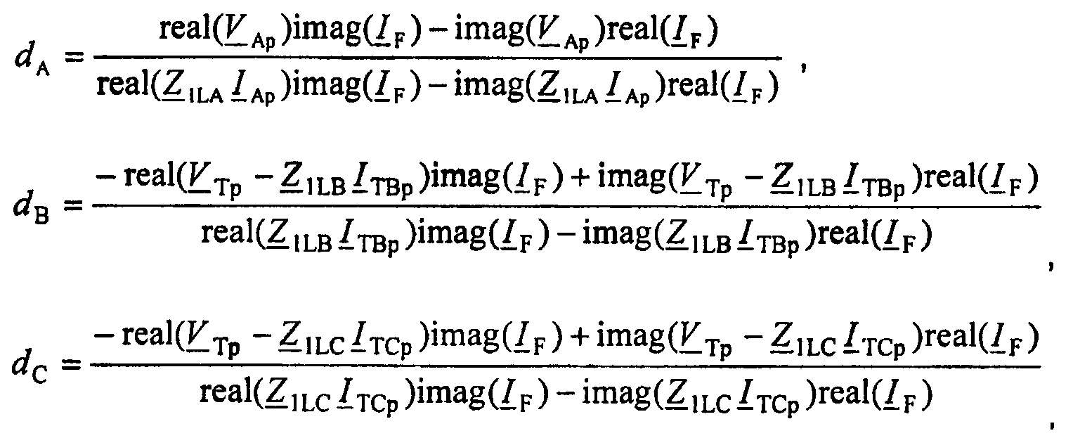
где:Where:
„real” обозначает действительную часть заданной величины;"Real" denotes the real part of a given value;
„imag” обозначает мнимую часть заданной величины;“Imag” means the imaginary part of a given quantity;
V Ap - обозначает напряжение на контуре повреждения, определяемое в предположении, что повреждение произошло на участке LA; V Ap - denotes the voltage on the damage circuit, determined on the assumption that the damage occurred on the LA;
V Tp - обозначает напряжение на контуре повреждения, определяемое в предположении, что повреждение произошло на участке LB или LC; V Tp - indicates the voltage on the damage circuit, determined on the assumption that the damage occurred on the LB or LC;
I Ap - обозначает контурный ток повреждения, определяемый в предположении, что повреждение произошло на участке LA; I Ap - denotes the loop fault current, determined under the assumption that the damage occurred in the LA area;
I TBp - обозначает контурный ток повреждения, определяемый в предположении, что повреждение произошло на участке LB; I TBp - indicates the loop fault current, determined under the assumption that the fault occurred in the LB section;
I TCp - обозначает контурный ток повреждения, определяемый в предположении, что повреждение произошло на участке LC линии; I TCp - indicates the loop fault current, determined on the assumption that the fault occurred on the LC line section;
I F - обозначает полный ток повреждения; I F - indicates the total fault current;
Z 1LA=R1LA+jω1L1LA - обозначает импеданс участка LA линии для положительной последовательности; Z 1LA = R 1LA + jω 1 L 1LA - indicates the impedance of the portion of the LA line for a positive sequence;
Z 1LB=R1LB+jω1L1LB - обозначает импеданс участка LB линии для положительной последовательности; Z 1LB = R 1LB + jω 1 L 1LB - indicates the impedance of the portion of the LB line for a positive sequence;
Z 1LC=R1LC+jω1L1LC - обозначает импеданс участка LC линии для положительной последовательности; Z 1LC = R 1LC + jω 1 L 1LC - indicates the impedance of the portion of the LC line for a positive sequence;
R1LA, R1LB, R1LC - сопротивление для положительной последовательности для участков LA, LB, LC линии соответственно;R 1LA , R 1LB , R 1LC - resistance for a positive sequence for sections of LA, LB, LC lines, respectively;
L1LA, L1LB, L1LC - индуктивность для положительной последовательности для участков LA, LB, LC линии соответственно;L 1LA , L 1LB , L 1LC - inductance for a positive sequence for sections of LA, LB, LC lines, respectively;
ω1 - угловая частота переменного тока для основной частоты.ω 1 - the angular frequency of the alternating current for the fundamental frequency.
Предпочтительно, для трехтерминальных линий электропередачи сопротивления RFA, RFB, RFC в месте повреждения определяют из следующих уравнений:Preferably, for three-terminal power transmission lines, the resistance R FA , R FB , R FC at the fault location is determined from the following equations:
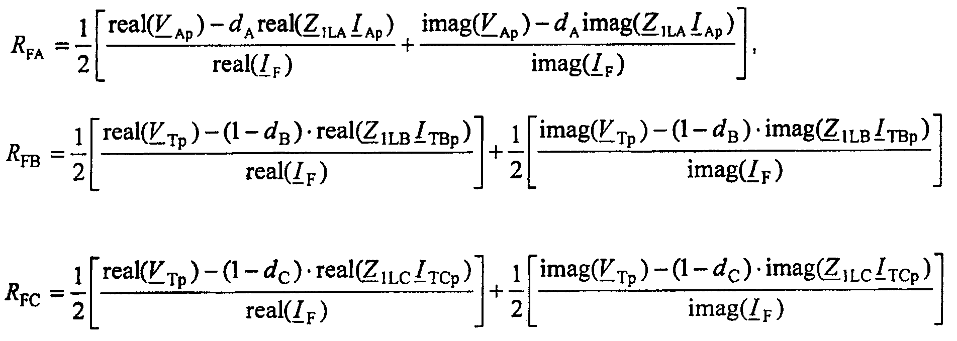
где:Where:
„real” обозначает действительную часть заданной величины;"Real" denotes the real part of a given value;
„imag” обозначает мнимую часть заданной величины;“Imag” means the imaginary part of a given quantity;
V Ap - обозначает напряжение на контуре повреждения, вычисляемое в предположении, что повреждение произошло на участке LA; V Ap - indicates the voltage on the damage circuit, calculated on the assumption that the damage occurred on the LA;
V Tp - обозначает напряжение на контуре повреждения, вычисляемое в предположении, что повреждение произошло на участке LB или LC; V Tp - indicates the voltage on the fault loop, calculated on the assumption that the damage occurred on the LB or LC;
I Ap - обозначает контурный ток повреждения, вычисляемый в предположении, что повреждение произошло на участке LA; I Ap - denotes the fault loop current, calculated on the assumption that the fault occurred in LA;
I TBp - обозначает контурный ток повреждения, вычисляемый в предположении, что повреждение произошло на участке LB; I TBp - indicates the loop fault current, calculated on the assumption that the fault occurred in the LB section;
I TCp - обозначает контурный ток повреждения, вычисляемый в предположении, что повреждение произошло на участке LC линии; I TCp - indicates the loop fault current, calculated on the assumption that the fault occurred on the LC line section;
I F - обозначает полный ток повреждения; I F - indicates the total fault current;
Z 1LA=R1LA+jω1L1LA - обозначает импеданс участка LA линии для положительной последовательности; Z 1LA = R 1LA + jω 1 L 1LA - indicates the impedance of the portion of the LA line for a positive sequence;
Z 1LB=R1LB+jω1L1LB - обозначает импеданс участка LB линии для положительной последовательности; Z 1LB = R 1LB + jω 1 L 1LB - indicates the impedance of the portion of the LB line for a positive sequence;
Z 1LC=R1LC+jω1L1LC R1LA - обозначает импеданс участка LC линии для положительной последовательности; Z 1LC = R 1LC + jω 1 L 1LC R 1LA - indicates the impedance of the portion of the LC line for a positive sequence;
R1LA, R1LB, R1LC - сопротивление для положительной последовательности для участков LA, LB, LC линии, соответственно;R 1LA , R 1LB , R 1LC - resistance for a positive sequence for sections of LA, LB, LC lines, respectively;
L1LC L1LA, L1LB, L1LC - индуктивность для положительной последовательности для участков LA, LB, LC линии, соответственно;L 1LC L 1LA , L 1LB , L 1LC - inductance for a positive sequence for sections of LA, LB, LC lines, respectively;
ω1 - угловая частота переменного тока для основной частоты;ω 1 is the angular frequency of the alternating current for the fundamental frequency;
dA - обозначает расстояние от начала линии до точки повреждения;d A - indicates the distance from the beginning of the line to the point of damage;
dB - обозначает расстояние от конца линии до точки повреждения;d B - indicates the distance from the end of the line to the point of damage;
dC - обозначает расстояние от конца линии передачи с ответвлениями до точки повреждения.d C - indicates the distance from the end of the transmission line with branches to the point of damage.
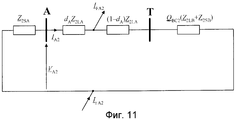
Предпочтительно, для трехтерминальных линий электропередачи, импеданс эквивалентного источника для отрицательной последовательной составляющей (Z 2SB)SUB_A) и для инкрементной положительной последовательной составляющей (Z Δ1SB)SUB_A) вычисляют в предположении, что повреждение произошло на участке LA линии, согласно уравнению:Preferably, for three-terminal power lines, the impedance of the equivalent source for the negative serial component ( Z 2SB ) SUB_A ) and for the incremental positive serial component ( Z Δ1SB ) SUB_A ) is calculated under the assumption that the damage occurred on the portion of the LA line according to the equation:
где:Where:
нижний индекс i принимает значения i=2 для отрицательной последовательной составляющей, i=Δ1 для инкрементной положительной последовательной составляющей;subscript i takes values i = 2 for the negative sequential component, i = Δ1 for the incremental positive sequential component;
G iA - обозначает первый аналитический коэффициент для отрицательной последовательной составляющей, определяемой из анализа эквивалентной принципиальной схемы системы, подобно показанной на фиг.11, и/или для инкрементной положительной последовательной составляющей, аналитически определяемой из эквивалентной принципиальной схемы системы, показанной на фиг.12; G iA - denotes the first analytical coefficient for the negative serial component determined from the analysis of the equivalent circuit diagram of the system, similar to that shown in FIG. 11, and / or for the incremental positive serial component analytically determined from the equivalent circuit diagram of the system shown in FIG. 12;
I Ai - обозначает отрицательную и/или инкрементную положительную последовательную составляющую тока, измеренного в начале линии; I Ai - denotes the negative and / or incremental positive sequential component of the current measured at the beginning of the line;
H Ai - обозначает второй аналитический коэффициент для отрицательной последовательной составляющей, определяемой из анализа эквивалентной принципиальной схемы системы, показанной на фиг.11, и/или для инкрементной положительной последовательной составляющей, аналитически определяемой из эквивалентной принципиальной схемы системы, показанной на фиг.12; H Ai - denotes the second analytical coefficient for the negative sequential component determined from the analysis of the equivalent circuit diagram of the system shown in Fig.11, and / or for the incremental positive serial component analytically determined from the equivalent circuit diagram of the system shown in Fig.12;
I FAi - обозначает отрицательную последовательную составляющую полного тока повреждения, определяемую из анализа эквивалентной принципиальной схемы системы, показанной на фиг.11, и/или инкрементную положительную последовательную составляющую полного тока повреждения, определяемую из эквивалентной принципиальной схемы системы, показанной на фиг.12; I FAi - denotes the negative sequential component of the total fault current determined from the analysis of the equivalent circuit diagram of the system shown in Fig. 11 and / or the incremental positive serial component of the total fault current determined from the equivalent circuit diagram of the system shown in Fig. 11;
Q BCi - обозначает отношение отрицательной последовательной составляющей тока, измеренной на конце линии, и суммы отрицательных последовательных составляющих сигналов тока, измеренных на конце линии и на конце линии передачи с ответвлениями, и/или отношение инкрементной положительной последовательной составляющей тока, измеренной на конце линии, и суммы инкрементных положительных последовательных составляющих сигналов тока, измеренных на конце линии и на конце линии передачи с ответвлениями. Q BCi - denotes the ratio of the negative serial component of the current measured at the end of the line and the sum of the negative serial components of the current signals measured at the end of the line and at the end of the transmission line with branches, and / or the ratio of the incremental positive serial component of the current measured at the end of the line, and the sum of the incremental positive sequential components of the current signals measured at the end of the line and at the end of the transmission line with branches.
Предпочтительно, для трехтерминальных линий электропередачи, импеданс (Z 2SC)SUB_A) эквивалентного источника для отрицательной последовательной составляющей и (Z Δ1SC)SUB_A) для инкрементной положительной последовательной составляющей вычисляют в предположении, что повреждение произошло на участке LA линии, из следующего уравнения:Preferably, for three-terminal power lines, the impedance ( Z 2SC ) SUB_A ) of the equivalent source for the negative serial component and ( Z Δ1SC ) SUB_A ) for the incremental positive serial component is calculated under the assumption that the damage occurred on the portion of the LA line from the following equation:
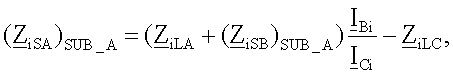
где:Where:
нижний индекс i принимает значения i=2 для отрицательной последовательной составляющей, i=Δ1 для инкрементной положительной последовательной составляющей;subscript i takes values i = 2 for the negative sequential component, i = Δ1 for the incremental positive sequential component;
(Z iSB)SUB_A) - обозначает импеданс эквивалентных источников для отрицательной последовательной составляющей и/или для инкрементной положительной последовательной составляющей, вычисляемой в предположении, что повреждение произошло на участке LA линии;( Z iSB ) SUB_A ) - indicates the impedance of equivalent sources for the negative serial component and / or for the incremental positive serial component, calculated on the assumption that the damage occurred on the portion of the LA line;
Z iLB - обозначает импеданс участка LB линии для отрицательной последовательной составляющей и/или для инкрементной положительной последовательной составляющей, где: Z Δ1LB=Z 1LB; Z iLB - denotes the impedance of the portion of the LB line for the negative serial component and / or for the incremental positive serial component, where: Z Δ1LB = Z 1LB ;
Z 1LB - обозначает импеданс участка LB линии для положительной последовательной составляющей; Z 1LB - indicates the impedance of the portion of the LB line for the positive serial component;
Z iLC - обозначает импеданс участка LC линии для отрицательной последовательной составляющей и/или импеданс участка LC линии для инкрементной положительной последовательной составляющей, где Z 2LC=Z 1LC и Z Δ1LC=Z 1LC; Z iLC - denotes the impedance of the portion of the LC line for the negative serial component and / or the impedance of the portion of the LC line for the incremental positive sequential component, where Z 2LC = Z 1LC and Z Δ1LC = Z 1LC ;
Z 1LC - обозначает импеданс участка LC линии для положительной последовательной составляющей; Z 1LC - indicates the impedance of the portion of the LC line for the positive serial component;
I Bi - обозначает отрицательную последовательную составляющую и/или инкрементную положительную последовательную составляющую тока, измеренную на конце линии; I Bi - denotes a negative sequential component and / or incremental positive sequential component of the current, measured at the end of the line;
I Ci - обозначает отрицательную последовательную составляющую и/или инкрементную положительную последовательную составляющую тока, измеренную на конце ответвления. I Ci - denotes the negative sequential component and / or the incremental positive sequential component of the current, measured at the end of the branch.
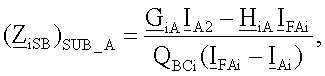
Предпочтительно, для трехтерминальных линий электропередачи, импеданс эквивалентного источника для отрицательной последовательной составляющей (Z 2SB)SUB_B) и для инкрементной положительной последовательной составляющей (Z Δ1SB)SUB_B) определяют в предположении, что повреждение произошло на участке LB линии, из следующего уравнения:Preferably, for three-terminal power lines, the impedance of the equivalent source for the negative serial component ( Z 2SB ) SUB_B ) and for the incremental positive serial component ( Z Δ1SB ) SUB_B ) is determined under the assumption that the damage occurred on the section of the LB line, from the following equation:
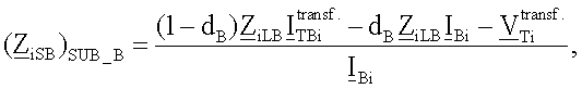
где:Where:
нижний индекс i принимает значения i=2 для отрицательной последовательной составляющей, i=Δ1 для инкрементной положительной последовательной составляющей;subscript i takes values i = 2 for the negative sequential component, i = Δ1 for the incremental positive sequential component;
dB - обозначает расстояние от конца линии до точки повреждения;d B - indicates the distance from the end of the line to the point of damage;
Z iLB - обозначает импеданс участка LB линии для отрицательной последовательной составляющей и/или для положительной последовательной составляющей, где: Z Δ1LB=Z 1LB; Z iLB - denotes the impedance of the portion of the LB line for the negative serial component and / or for the positive serial component, where: Z Δ1LB = Z 1LB ;
Z Δ1LB - обозначает импеданс участка LB линии для положительной последовательной составляющей; Z Δ1LB - indicates the impedance of the portion of the LB line for the positive serial component;
![]()
![]()
I Bi - обозначает отрицательную последовательную составляющую и/или инкрементную положительную последовательную составляющую тока, измеренную на конце линии; I Bi - denotes a negative sequential component and / or incremental positive sequential component of the current, measured at the end of the line;
![]()
![]()
Предпочтительно, для трехтерминальных линий электропередачи, импеданс эквивалентного источника для отрицательной последовательной составляющей (Z 2SC)SUB_B) и для инкрементной положительной последовательной составляющей (Z Δ1SC)SUB_B) вычисляют в предположении, что повреждение произошло на участке LB линии, из следующего уравнения:Preferably, for three-terminal power lines, the impedance of the equivalent source for the negative serial component ( Z 2SC ) SUB_B ) and for the incremental positive serial component ( Z Δ1SC ) SUB_B ) is calculated under the assumption that the damage occurred on the portion of the LB line, from the following equation:
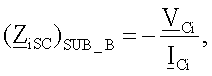
где:Where:
нижний индекс i принимает значения i=2 для отрицательной последовательной составляющей, i=Δ1 для инкрементной положительной последовательной составляющей;subscript i takes values i = 2 for the negative sequential component, i = Δ1 for the incremental positive sequential component;
V Ci - обозначает вычисленную отрицательную последовательную составляющую и/или инкрементную положительную последовательную составляющую напряжения на конце линии передачи с ответвлениями; V Ci - denotes the calculated negative series component and / or incremental positive series component of the voltage at the end of the transmission line with branches;
I Ci - обозначает отрицательную последовательную составляющую и/или инкрементную положительную последовательную составляющую тока, измеренную на конце ответвления. I Ci - denotes the negative sequential component and / or the incremental positive sequential component of the current, measured at the end of the branch.
Предпочтительно, для трехтерминальных линий электропередачи, импеданс эквивалентного источника для отрицательной последовательной составляющей (Z 2SC)SUB_C и для инкрементной положительной последовательной составляющей (Z Δ1SC)SUB_C вычисляют в предположении, что повреждение произошло на участке LC линии, из следующего уравнения:Preferably, for three-terminal power lines, the impedance of the equivalent source for the negative serial component ( Z 2SC ) SUB_C and for the incremental positive serial component ( Z Δ1SC ) SUB_C is calculated under the assumption that the damage occurred on the LC line section from the following equation:

где:Where:
нижний индекс i принимает значения i=2 для отрицательной последовательной составляющей, i=Δ1 для инкрементной положительной последовательной составляющей;subscript i takes values i = 2 for the negative sequential component, i = Δ1 for the incremental positive sequential component;
dc - обозначает расстояние от конца линии передачи с ответвлениями до точки повреждения;d c - indicates the distance from the end of the transmission line with branches to the point of damage;
Z iLC - обозначает импеданс участка LC линии для отрицательной последовательной составляющей и/или для инкрементной положительной последовательной составляющей, где: Z 2LC=Z 1LC и Z Δ1LC=Z 1LC; Z iLC - indicates the impedance of the LC line section for the negative serial component and / or for the incremental positive serial component, where: Z 2LC = Z 1LC and Z Δ1LC = Z 1LC ;
Z 1LC - обозначает импеданс участка LC линии для положительной последовательной составляющей; Z 1LC - indicates the impedance of the portion of the LC line for the positive serial component;
![]()
![]()
I Ci - обозначает отрицательную последовательную составляющую и/или инкрементную положительную последовательную составляющую тока, измеренную на конце ответвления; I Ci - denotes a negative sequential component and / or incremental positive sequential component of the current, measured at the end of the branch;
![]()
![]()
Предпочтительно, для трехтерминальных линий электропередачи, импеданс эквивалентного источника для отрицательной последовательной составляющей (Z 2SB)SUB_C и для инкрементной положительной последовательной составляющей (Z Δ1SB)SUB_C вычисляют в предположении, что повреждение произошло на участке LC линии, из следующего уравнения:Preferably, for three-terminal power lines, the impedance of the equivalent source for the negative serial component ( Z 2SB ) SUB_C and for the incremental positive serial component ( Z Δ1SB ) SUB_C is calculated under the assumption that the damage occurred on the LC line section from the following equation:
где:Where:
нижний индекс i принимает значения i=2 для отрицательной последовательной составляющей, i=Δ1 для инкрементной положительной последовательной составляющей;subscript i takes values i = 2 for the negative sequential component, i = Δ1 for the incremental positive sequential component;
V Bi - обозначает вычисленную отрицательную последовательную и/или инкрементную положительную последовательную составляющую напряжения на конце линии; V Bi - denotes the calculated negative series and / or incremental positive series component of the voltage at the end of the line;
I Bi - обозначает отрицательную последовательную и/или инкрементную положительную последовательную составляющую тока, измеренного на конце линии. I Bi - denotes the negative sequential and / or incremental positive sequential component of the current measured at the end of the line.
Предпочтительно, для многотерминальных линий электропередачи расстояния от начала линии до точки повреждения (d1), от конца линии до точки повреждения (d(2n-3)), от конца линии до точки повреждения (d(2k-2)), от точки ответвления до точки повреждения на участке линии между двумя точками ответвления {d(2k-1)) определяют из следующих уравнений:Preferably, for multi-terminal power lines, the distance from the beginning of the line to the point of damage (d 1 ), from the end of the line to the point of damage (d ( 2n-3 )), from the end of the line to the point of damage (d (2k-2 )), from the point branches to the point of damage on the line segment between two branch points {d ( 2k-1 )) is determined from the following equations:
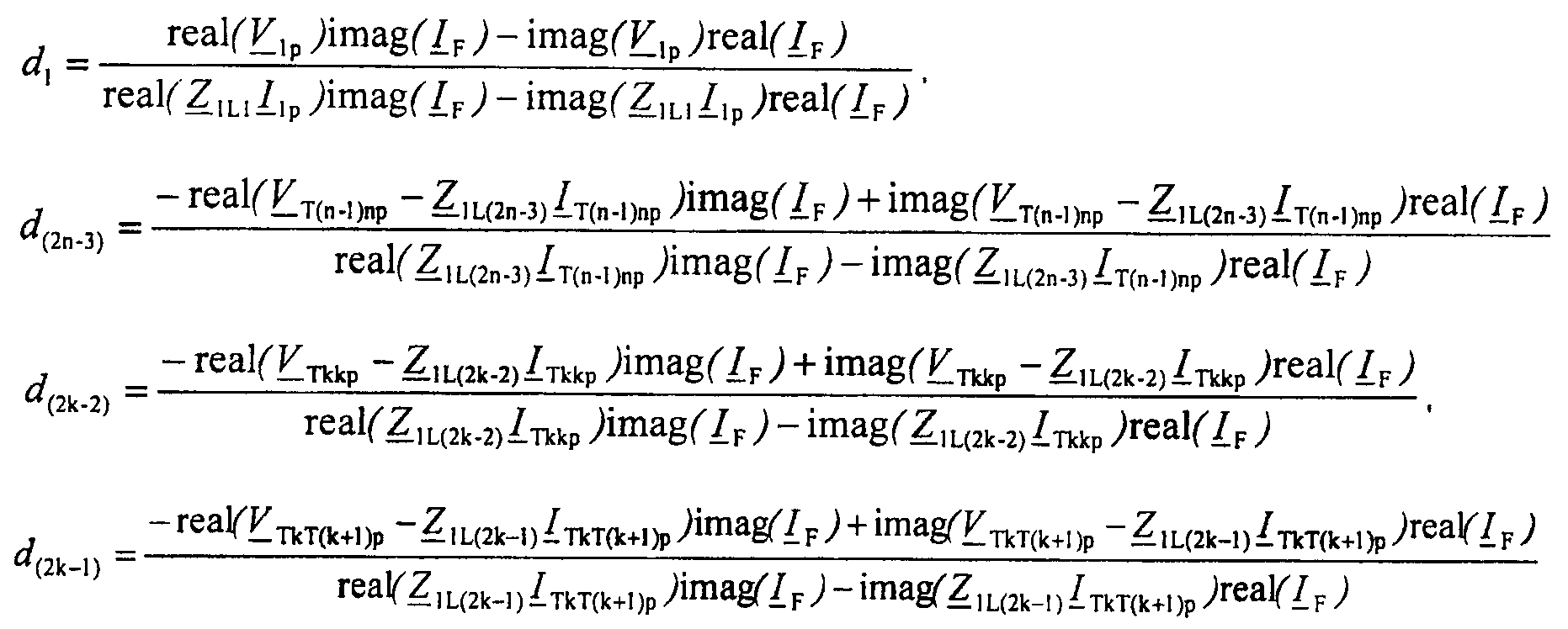
где:Where:
„real” обозначает действительную часть заданной величины;"Real" denotes the real part of a given value;
„imag” обозначает мнимую часть заданной величины;“Imag” means the imaginary part of a given quantity;
V 1p - напряжение на контуре повреждения, вычисляемое в предположении, что повреждение произошло на участке L1 линии; V 1p is the voltage on the damage circuit, calculated under the assumption that the damage occurred on the L1 line section;
I 1p - контурный ток повреждения, вычисляемый в предположении, что повреждение произошло на первом участке L1 линии; I 1p is the fault loop current calculated on the assumption that the fault occurred on the first section of the L1 line;
V T(n-1)np - напряжение на контуре повреждения, вычисляемое в предположении, что повреждение произошло на участке L(2n-3) линии; V T (n-1) np is the voltage on the damage circuit, calculated on the assumption that the damage occurred on the section L (2n-3) of the line;
I T(n-1)np - контурный ток повреждения, вычисляемый в предположении, что повреждение произошло на участке L(2n-3) линии; I T (n-1) np is the fault loop current calculated on the assumption that the fault occurred on a portion of the L (2n-3) line;
V Tkkp - напряжение на контуре повреждения, вычисляемое в предположении, что повреждение произошло в koй линии передачи с ответвлениями; V Tkkp is the voltage on the damage circuit, calculated on the assumption that the damage occurred on the k- th transmission line with branches;
I Tkkp - контурный ток повреждения, вычисляемый в предположении, что повреждение произошло в koй линии передачи с ответвлениями; I Tkkp - contour fault current, calculated under the assumption that the damage occurred in the k- th transmission line with branches;
V TkT(k+1)p - напряжение на контуре повреждения, вычисляемое в предположении, что повреждение произошло на участке линии между двумя точками ответвления; V TkT (k + 1) p is the voltage on the damage circuit, calculated under the assumption that the damage occurred on a section of the line between two branch points;
I TkT(k+1)p - контурный ток повреждения, вычисляемый в предположении, что повреждение произошло на участке линии между двумя точками ответвления; I TkT (k + 1) p is the fault loop current calculated on the assumption that the fault occurred on a section of the line between two branch points;
I F - полный ток повреждения; I F is the total fault current;
Z 1L1 - импеданс участка L1 линии для положительной последовательной составляющей; Z 1L1 is the impedance of the line section L1 for the positive serial component;
Z 0L1- импеданс участка L1 линии для нулевой последовательной составляющей; Z 0L1 is the impedance of the line section L1 for the zero serial component;
Z 1L(2n-3) - импеданс участка L(2n-3) линии для положительной последовательной составляющей; Z 1L (2n-3) is the impedance of the portion of the L (2n-3) line for the positive serial component;
Z 0L(2n-3) - импеданс участка L(2n-3) линии для нулевой последовательной составляющей; Z 0L (2n-3) is the impedance of the portion of the L (2n-3) line for the zero serial component;
Z 1L(2k-2) - импеданс участка L(2k-2) линии для положительной последовательной составляющей; Z 1L (2k-2) is the impedance of the portion of the L (2k-2) line for the positive serial component;
Z 0L(2k-2) - импеданс участка L(2k-2) линии для нулевой последовательной составляющей; Z 0L (2k-2) is the impedance of the portion of the L (2k-2) line for the zero serial component;
Z 1L(2k-1) - импеданс участка L(2k-1) линии для положительной последовательной составляющей; Z 1L (2k-1) is the impedance of the portion of the L (2k-1) line for the positive serial component;
Z 0L(2k-1) - импеданс участка L(2k-1) линии для нулевой последовательной составляющей; Z 0L (2k-1) is the impedance of the portion L (2k-1) of the line for the zero sequential component;
k - номер точки ответвления;k is the number of the branch point;
n - номер терминала линии.n is the terminal number of the line.
Предпочтительно, для многотерминальных линий электропередачи сопротивления (R 1F), (R (2n-3)F), (R (2k-2)F), (R (2k-1)F) в месте повреждения вычисляют из следующих уравнений:Preferably, for multi-terminal power transmission lines, the resistance ( R 1F ), ( R (2n-3) F ), ( R (2k-2) F ), ( R (2k-1) F ) at the fault location is calculated from the following equations:
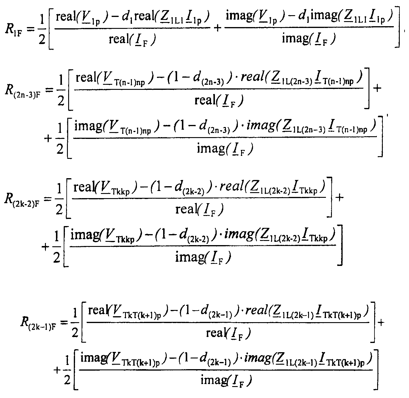
где:Where:
„real” обозначает действительную часть заданной величины;"Real" denotes the real part of a given value;
„imag” обозначает мнимую часть заданной величины;“Imag” means the imaginary part of a given quantity;
(d1) - расстояние до повреждения от начала линии до точки повреждения;(d 1 ) is the distance to the damage from the beginning of the line to the point of damage;
(d(2n-3)) - расстояние до повреждения от конца линии до точки повреждения;(d ( 2n-3 )) is the distance to the damage from the end of the line to the point of damage;
(d(2k-2)) - расстояние до повреждения от конца линии передачи с ответвлениями до точки повреждения;(d (2k-2 )) is the distance to the damage from the end of the transmission line with branches to the point of damage;
{d(2k-1)) - расстояние до повреждения на участке линии между двумя точками ответвления;{d ( 2k-1 )) is the distance to the damage on the line section between two branch points;
V 1p - напряжение на контуре повреждения, вычисляемое в предположении, что повреждение произошло на первом участке L1 линии; V 1p is the voltage on the damage circuit, calculated on the assumption that the damage occurred on the first section of the L1 line;
I 1p - контурный ток повреждения, вычисляемый в предположении, что повреждение произошло на первом участке L1 линии; I 1p is the fault loop current calculated on the assumption that the fault occurred on the first section of the L1 line;
V T(n-1)np - напряжение на контуре повреждения, вычисляемое в предположении, что повреждение произошло на участке L(2n-3) линии; V T (n-1) np is the voltage on the damage circuit, calculated on the assumption that the damage occurred on the section L (2n-3) of the line;
I T(n-1)np - контурный ток повреждения, вычисляемый в предположении, что повреждение произошло на участке L(2n-3) линии; I T (n-1) np is the fault loop current calculated on the assumption that the fault occurred on a portion of the L (2n-3) line;
V Tkkp - напряжение на контуре повреждения, вычисляемое в предположении, что повреждение произошло в koй линии передачи с ответвлениями; V Tkkp is the voltage on the damage circuit, calculated on the assumption that the damage occurred on the k- th transmission line with branches;
I Tkkp - контурный ток повреждения, вычисляемый в предположении, что повреждение произошло в koй линии передачи с ответвлениями; I Tkkp - contour fault current, calculated under the assumption that the damage occurred in the k- th transmission line with branches;
V TkT(k+1)p - напряжение на контуре повреждения, вычисляемое в предположении, что повреждение произошло на участке линии между двумя точками ответвления; V TkT (k + 1) p is the voltage on the damage circuit, calculated under the assumption that the damage occurred on a section of the line between two branch points;
I TkT(k+1)p - контурный ток повреждения, вычисляемый в предположении, что повреждение произошло на участке линии между двумя точками ответвления; I TkT (k + 1) p is the fault loop current calculated on the assumption that the fault occurred on a section of the line between two branch points;
I F - полный ток повреждения; I F is the total fault current;
Z 1L1 - импеданс участка L1 линии для положительной последовательной составляющей; Z 1L1 is the impedance of the line section L1 for the positive serial component;
Z 0L1- импеданс участка L1 линии для нулевой последовательной составляющей; Z 0L1 is the impedance of the line section L1 for the zero serial component;
Z 1L(2n-3) - импеданс участка L(2n-3) линии для положительной последовательной составляющей; Z 1L (2n-3) is the impedance of the portion of the L (2n-3) line for the positive serial component;
Z 0L(2n-3) - импеданс участка L(2n-3) линии для нулевой последовательной составляющей; Z 0L (2n-3) is the impedance of the portion of the L (2n-3) line for the zero serial component;
Z 1L(2k-2) - импеданс участка L(2k-2) линии для положительной последовательной составляющей; Z 1L (2k-2) is the impedance of the portion of the L (2k-2) line for the positive serial component;
Z 0L(2k-2) - импеданс участка L(2k-2) линии для нулевой последовательной составляющей; Z 0L (2k-2) is the impedance of the portion of the L (2k-2) line for the zero serial component;
Z 1L(2k-1) - импеданс участка L(2k-1) линии для положительной последовательной составляющей; Z 1L (2k-1) is the impedance of the portion of the L (2k-1) line for the positive serial component;
Z 0L(2k-1) - импеданс участка L(2k-1) линии для нулевой последовательной составляющей; Z 0L (2k-1) is the impedance of the portion L (2k-1) of the line for the zero sequential component;
k - номер точки ответвления;k is the number of the branch point;
n - номер терминала линии.n is the terminal number of the line.
Предпочтительно, для многотерминальных линий электропередачи импеданс эквивалентных источников для отрицательной последовательной составляющей (Z 2S1) или для инкрементной положительной последовательной составляющей (Z Δ1S1) вычисляют в предположении, что повреждение расположено на участке линии между началом линии и первой точкой ответвления, согласно следующему уравнению:Preferably, for multi-terminal power lines, the impedance of equivalent sources for the negative serial component ( Z 2S1 ) or for the incremental positive serial component ( Z Δ1S1 ) is calculated under the assumption that the damage is located on the line section between the beginning of the line and the first branch point, according to the following equation:
где:Where:
i=2 для отрицательной последовательной составляющей, i=Δ1 для инкрементной положительной последовательной составляющей;i = 2 for the negative sequential component, i = Δ1 for the incremental positive sequential component;
V 1i - напряжение, измеренное на станции 1 для отдельных симметричных составляющих (первый нижний индекс), а второй нижний индекс для отрицательной последовательной составляющей будет равен 2, и для инкрементной положительной последовательной составляющей будет индекс Δ1; V 1i is the voltage measured at
I 1i - ток, измеренный на станции 1 для отдельных симметричных составляющих (первый нижний индекс), а второй нижний индекс для отрицательной последовательной составляющей будет равен 2, и для инкрементной положительной последовательной составляющей индекс будет Δ1. I 1i is the current measured at
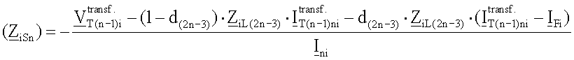
Предпочтительно, для многотерминальных линий электропередачи, импеданс ((Z 2S(n))) эквивалентного источника для отрицательной последовательной составляющей и ((Z Δ1S(n))) для инкрементной положительной последовательной составляющей определяют в предположении, что повреждение расположено на участке линии между концом линии и последней точкой ответвления, из следующего уравнения:Preferably, for multi-terminal power lines, the impedance (( Z 2S (n) )) of the equivalent source for the negative serial component and (( Z Δ1S (n) )) for the incremental positive serial component is determined under the assumption that the damage is located on the portion of the line between the end line and last branch point, from the following equation:
где:Where:
i=2 для отрицательной последовательной составляющей, i=Δ1 для инкрементной положительной последовательной составляющей;i = 2 for the negative sequential component, i = Δ1 for the incremental positive sequential component;
![]()
![]()
d(2n-3) - расстояние до повреждения от конца линии до точки повреждения,d (2n-3) - distance to damage from the end of the line to the point of damage,
Z iL(2n-3) - импеданс участка L(2n-3) линии для отрицательной последовательной составляющей i=2 или для инкрементной положительной последовательной составляющей i=Δ1; Z iL (2n-3) is the impedance of the portion of the L (2n-3) line for the negative sequential component i = 2 or for the incremental positive sequential component i = Δ1;
![]()
![]()
I Fi - полный ток повреждения для отрицательной последовательной составляющей i=2 или для инкрементной положительной последовательной составляющей i=Δ1; I Fi is the total fault current for the negative serial component i = 2 or for the incremental positive serial component i = Δ1;
I ni - ток, измеренный на последней станции n для отдельных симметричных составляющих (первый нижний индекс), а второй нижний индекс для отрицательной последовательной составляющей будет равен 2, и для инкрементной положительной последовательной составляющей индекс будет Δ1. I ni is the current measured at the last station n for individual symmetrical components (the first subscript), and the second subscript for the negative sequential component will be 2, and for the incremental positive sequential component, the index will be Δ1.
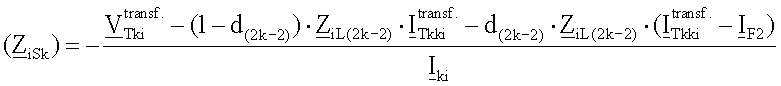
Предпочтительно, для многотерминальных линий электропередачи импеданс эквивалентного источника для отрицательной последовательной составляющей ((Z 2Sk)) и для инкрементной положительной последовательной составляющей ((Z Δ1Sk)) определяют в предположении, что повреждение расположено на линии передачи с ответвлениями, из следующего уравнения:Preferably, for multi-terminal power lines, the impedance of the equivalent source for the negative serial component (( Z 2Sk )) and for the incremental positive serial component (( Z Δ1Sk )) is determined under the assumption that the damage is located on the transmission line with branches, from the following equation:
где:Where:
![]()
![]()
d(2k-2) - расстояние до повреждения от конца линии передачи с ответвлениями до точки повреждения Tk;d (2k-2) - distance to damage from the end of the transmission line with branches to the damage point Tk;
Z iL(2k-2) - импеданс участка L(2k-2) линии для отрицательной последовательной составляющей i=2 или для инкрементной положительной последовательной составляющей i=Δ1; Z iL (2k-2) is the impedance of a portion of the L (2k-2) line for the negative sequential component i = 2 or for the incremental positive sequential component i = Δ1;
![]()
![]()
I Fi - полный ток повреждения для отрицательной последовательной составляющей i=2 или для инкрементной положительной последовательной составляющей i=Δ1; I Fi is the total fault current for the negative serial component i = 2 or for the incremental positive serial component i = Δ1;
I ki - ток, измеренный на станции k для отдельных симметричных составляющих (первый нижний индекс), а второй нижний индекс для отрицательной последовательной составляющей будет равен 2, и для инкрементной положительной последовательной составляющей индекс будет Δ1. I ki is the current measured at station k for individual symmetrical components (the first subscript), and the second subscript for the negative sequential component will be 2, and for the incremental positive sequential component, the index will be Δ1.
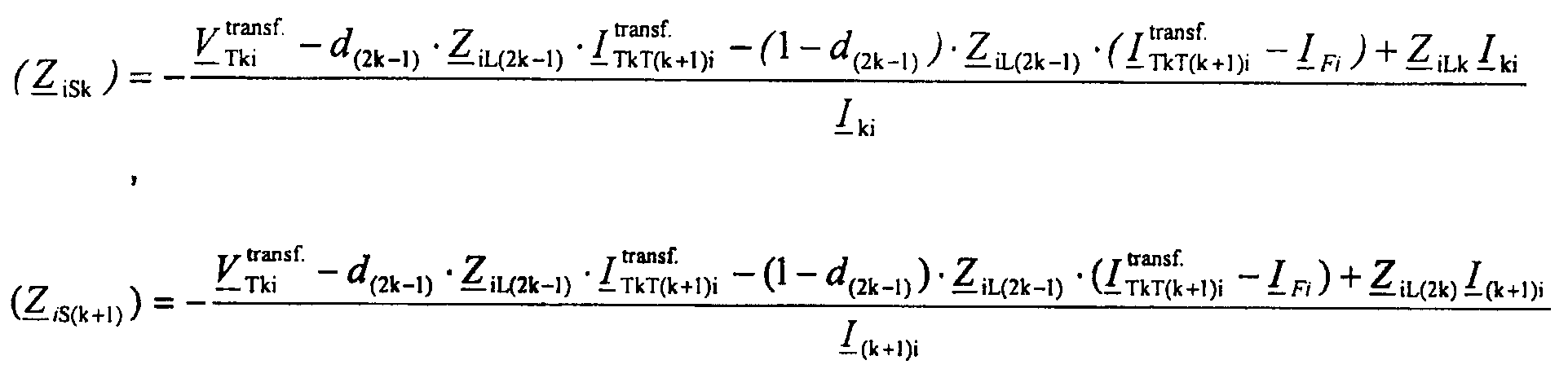
Предпочтительно, для многотерминальных линий электропередачи, импеданс эквивалентного источника для отрицательной последовательной составляющей ((Z 2Sk)) и ((Z 2S(k+1))) и для инкрементной положительной последовательной составляющей ((Z Δ1Sk)) и ((Z Δ1S(k+1))) вычисляют в предположении, что повреждение расположено на участке линии между двумя следующими друг за другом точками ответвления, из следующих уравнений:Preferably, for multi-terminal power lines, the equivalent source impedance for the negative serial component (( Z 2Sk )) and (( Z 2S (k + 1) )) and for the incremental positive serial component (( Z Δ1Sk )) and (( Z Δ1S ( k + 1) )) is calculated under the assumption that the damage is located on a section of the line between two consecutive branch points from the following equations:
где:Where:
![]()
![]()
d(2k-1) - расстояние до повреждения на участке линии между двумя точками ответвления;d (2k-1) is the distance to damage on the line section between two branch points;
Z iL(2k-1) - импеданс участка L(2k-1) линии для отрицательной последовательной составляющей i=2 или для инкрементной положительной последовательной составляющей i=Δ1; Z iL (2k-1) is the impedance of the line segment L (2k-1) for the negative sequential component i = 2 or for the incremental positive sequential component i = Δ1;
![]()
![]()
I Fi - полный ток повреждения для отрицательной последовательной составляющей i=2 или для инкрементной положительной последовательной составляющей i=Δ1; I Fi is the total fault current for the negative serial component i = 2 or for the incremental positive serial component i = Δ1;
I ki - ток, измеренный на станции k для отдельных симметричных составляющих (первый нижний индекс), а второй нижний индекс для отрицательной последовательной составляющей будет равен 2, и для инкрементной положительной последовательной составляющей будет равен Δ1; I ki is the current measured at station k for individual symmetrical components (the first subscript), and the second subscript for the negative sequential component will be 2, and for the incremental positive sequential component will be Δ1;
I (k+1)i - ток, измеренный на станции k+1 для отдельных симметричных составляющих (первый нижний индекс), а второй нижний индекс для отрицательной последовательной составляющей будет равен 2, и для инкрементной положительной последовательной составляющей индекс будет Δ1. I (k + 1) i is the current measured at station k + 1 for individual symmetrical components (the first subscript), and the second subscript for the negative sequential component will be 2, and for the incremental positive sequential component the index will be Δ1.
ПРЕИМУЩЕСТВАADVANTAGES
Преимущество способа определения места повреждения в линиях электропередачи состоит в том, что позволяет определять точку повреждения для системы электропередачи или распределительной системы как с пассивными, так и с активными ответвлениями.The advantage of the method of determining the location of damage in power lines is that it allows you to determine the point of damage for the power transmission system or distribution system with both passive and active branches.
Благодаря требуемым входным сигналам предложенный способ определения местоположения может применяться к дифференциальной токовой защите, что увеличивает функциональные возможности защитного реле. Таким образом, защитное реле, кроме свой основной характеристики, то есть индикации того, произошло повреждение в заданной защитной зоне или вне ее, может точно определять местоположение повреждения.Due to the required input signals, the proposed location method can be applied to differential current protection, which increases the functionality of the protective relay. Thus, the protective relay, in addition to its main characteristic, that is, an indication of whether damage has occurred in a given protective zone or outside it, can accurately determine the location of the damage.
Кроме того, предложенный способ является стойким к условиям перед повреждением, задаваемым направлением и объемом потока мощности перед повреждением.In addition, the proposed method is resistant to conditions before damage specified by the direction and volume of power flow before damage.
КРАТКОЕ ОПИСАНИЕ ЧЕРТЕЖЕЙBRIEF DESCRIPTION OF THE DRAWINGS
Способ согласно настоящему изобретению поясняется на примере предпочтительного варианта осуществления со ссылками на сопровождающие чертежи, на которых:The method according to the present invention is illustrated by the example of a preferred embodiment with reference to the accompanying drawings, in which:
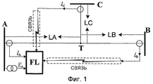
фиг.1 изображает электрическую схему для реализации способа определения повреждения трехтерминальной линии электропередачи с указанными участками LA, LB и LC, согласно изобретению;figure 1 depicts an electrical circuit for implementing a method for determining damage to a three-terminal power line with the indicated sections LA, LB and LC, according to the invention;
фиг.2 - принципиальную схему для положительной последовательной составляющей в предположении, что повреждение произошло на участке LA линии, согласно изобретению;FIG. 2 is a circuit diagram for a positive series component under the assumption that damage has occurred on a portion of an LA line according to the invention; FIG.
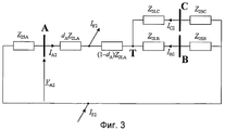
фиг.3 - принципиальную схему системы электропередачи для отрицательной последовательной составляющей в предположении, что повреждение произошло на участке LA линии, согласно изобретению;FIG. 3 is a schematic diagram of a power transmission system for a negative serial component under the assumption that damage has occurred on a portion of an LA line according to the invention;
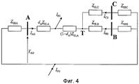
фиг.4 - принципиальную схему системы электропередачи для нулевой последовательной составляющей в предположении, что повреждение произошло на участке LA линии, согласно изобретению;FIG. 4 is a schematic diagram of a power transmission system for a zero series component under the assumption that damage has occurred on a portion of an LA line according to the invention;
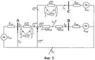
фиг.5 - принципиальную схему для положительной последовательной составляющей в предположении, что повреждение произошло на участке LB линии, согласно изобретению;5 is a circuit diagram for a positive series component under the assumption that damage has occurred on a portion of an LB line according to the invention;
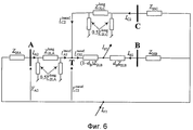
фиг.6 - принципиальную схему системы электропередачи для отрицательной последовательной составляющей в предположении, что повреждение произошло на участке LB линии, согласно изобретению;6 is a schematic diagram of a power transmission system for a negative serial component under the assumption that damage has occurred on a portion of an LB line according to the invention;
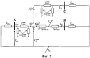
фиг.7 - принципиальную схему системы электропередачи для нулевой последовательной составляющей в предположении, что повреждение произошло на участке LB линии, согласно изобретению;FIG. 7 is a schematic diagram of a power transmission system for a zero series component, under the assumption that damage has occurred on a portion of an LB line according to the invention;
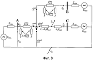
фиг.8 - принципиальную схему для положительной последовательной составляющей в предположении, что повреждение произошло на участке LC линии, согласно изобретению;Fig. 8 is a circuit diagram for a positive series component under the assumption that damage has occurred on a portion of an LC line according to the invention;
фиг.9 - принципиальную схему системы электропередачи для отрицательной последовательной составляющей в предположении, что повреждение произошло на участке LC линии, согласно изобретению;Fig. 9 is a schematic diagram of a power transmission system for a negative serial component under the assumption that damage has occurred on a portion of an LC line according to the invention;
фиг.10 - принципиальную схему системы электропередачи для нулевой последовательной составляющей в предположении, что повреждение произошло на участке LC линии, согласно изобретению;FIG. 10 is a schematic diagram of a power transmission system for a zero series component under the assumption that damage has occurred on a portion of an LC line according to the invention;
фиг.11 - принципиальную схему системы электропередачи для отрицательной последовательной составляющей в предположении, что повреждение произошло на участке LA линии, для вычисления импеданса эквивалентных систем, согласно изобретению;11 is a schematic diagram of a power transmission system for a negative serial component under the assumption that damage has occurred on a portion of an LA line to calculate the impedance of equivalent systems according to the invention;
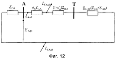
фиг.12 - принципиальную схему для инкрементной положительной последовательной составляющей в предположении, что повреждение произошло на участке LA линии, для вычисления импеданса эквивалентных систем, согласно изобретению;12 is a circuit diagram for an incremental positive series component under the assumption that damage has occurred on a portion of an LA line to calculate the impedance of equivalent systems according to the invention;
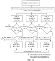
фиг.13 блок-схему последовательности операций, выполняемых при определении местоположения повреждений согласно заявленному способу трехтерминальной линии электропередачи, согласно изобретению;Fig. 13 is a flowchart for determining the location of damage according to the claimed method of a three-terminal power line according to the invention;
фиг.14 - электрическую схему системы электропередачи для осуществления способа для многотерминальной линии электропередачи, согласно изобретению;Fig. 14 is an electrical diagram of a power transmission system for implementing a method for a multi-terminal power transmission line according to the invention;
фиг.15 - принципиальную схему системы электропередачи для симметричных составляющих в предположении, что повреждение произошло на первом участке многотерминальной линии электропередачи, согласно изобретению;FIG. 15 is a schematic diagram of a power transmission system for symmetrical components under the assumption that damage has occurred in a first portion of a multi-terminal power transmission line according to the invention;
фиг.16 - принципиальную схему системы электропередачи для симметричных составляющих в предположении, что повреждение произошло на последнем участке многотерминальной линии электропередачи, согласно изобретению;FIG. 16 is a schematic diagram of a power transmission system for symmetrical components, on the assumption that damage has occurred on a last portion of a multi-terminal power transmission line according to the invention;
фиг.17 - фрагмент принципиальной схемы системы электропередачи для симметричных составляющих в предположении, что повреждение произошло на участке линии передачи с ответвлениями многотерминальной линии электропередачи, согласно изобретению;17 is a fragment of a schematic diagram of a power transmission system for symmetrical components, on the assumption that damage occurred on a portion of a transmission line with branches of a multi-terminal power transmission line according to the invention;
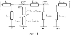
фиг.18 - фрагмент принципиальной схемы системы электропередачи для симметричных составляющих в предположении, что повреждение произошло на участке многотерминальной линии электропередачи между двумя точками ответвления, согласно изобретению;Fig. 18 is a fragment of a schematic diagram of a power transmission system for symmetrical components on the assumption that damage occurred on a portion of a multi-terminal power transmission line between two branch points, according to the invention;
фиг.19 блок-схему последовательности операций, выполняемых при определении местоположения повреждений согласно заявленному способу для многотерминальной линии электропередачи, согласно изобретению.FIG. 19 is a flowchart for determining the location of damage according to the claimed method for a multi-terminal power line according to the invention.
ОПИСАНИЕ ВАРИАНТА ОСУЩЕСТВЛЕНИЯ ИЗОБРЕТЕНИЯ ДЛЯ ТРЕХТЕРМИНАЛЬНОЙ ЛИНИИ ЭЛЕКТРОПЕРЕДАЧИDESCRIPTION OF THE EMBODIMENT FOR THE THREE-TERMINAL TRANSMISSION LINE
Система электропередачи (фиг.1) содержит три электростанции A, B и C. Станция A расположена в начале линии, станция B на конце этой линии и станция C после линии, которая в точке ответвления T ответвляется от линии между станциями AB. Точка ответвления T делит систему электропередачи на три участка LA, LB и LC. На станции A имеется прибор для обнаружения мест повреждения FL. Определение места повреждения выполняется с использованием моделей повреждений и контуров повреждений для симметричных составляющих и для различных типов повреждений, посредством применения подходящих распределенных коэффициентов, определяющих соотношение между симметричными составляющими полного тока повреждения, когда оценивается падение напряжения на сопротивлении в месте повреждения, задаваемых как a F1, a F2, a F0, и весовых коэффициентов a 1, a 2, a 0, задающих долю отдельных составляющих в полной модели контура повреждения. Анализ граничных условий для различных типов повреждений показывает, что имеется некоторая степень свободы, при определении распределенных коэффициентов, определяющих соотношение между симметричными составляющими полного тока повреждения, когда оценивается падение напряжения на сопротивлении в месте повреждения. Их выбор зависит от принятого предпочтения использования отдельных последовательных составляющих, в зависимости от типа повреждения. В настоящем примере варианта осуществления изобретения, чтобы гарантировать высокую точность определения места повреждения, падение напряжения на сопротивлении в месте повреждения оценивается с использованием:The power transmission system (FIG. 1) contains three power plants A, B and C. Station A is located at the beginning of the line, station B at the end of this line and station C after the line, which at branch point T branches off from the line between stations AB. Branch point T divides the transmission system into three sections LA, LB and LC. Station A has an instrument for locating FL lesions. Damage location is determined using damage models and damage contours for symmetrical components and for various types of damage, by applying appropriate distributed coefficients that determine the relationship between the symmetrical components of the total damage current when the voltage drop across the resistance at the damage location is estimated as a F1 , a F2 , a F0 , and weights a 1 , a 2 , a 0 , which specify the fraction of the individual components in the complete model of the damage contour. An analysis of the boundary conditions for various types of damage shows that there is a certain degree of freedom when determining distributed coefficients that determine the relationship between the symmetrical components of the total damage current when the voltage drop across the resistance at the location of the damage is estimated. Their choice depends on the accepted preference for using individual serial components, depending on the type of damage. In the present example of an embodiment of the invention, in order to guarantee high accuracy in determining the place of damage, the voltage drop across the resistance at the place of damage is evaluated using:
отрицательной последовательной составляющей полного тока повреждения для однофазных коротких замыканий на землю (a-g), (b-g), (c-g) и междуфазных коротких замыканий (a-b), (b-c)i(c-a);negative serial component of the total fault current for single-phase earth faults (a-g), (b-g), (c-g) and interphase short-circuits (a-b), (b-c) i (c-a);
отрицательной последовательной составляющей и нулевой последовательной составляющей для двухфазных коротких замыканий на землю (a-b-g), (b-c-g), (c-a-g);negative serial component and zero serial component for two-phase earth faults (a-b-g), (b-c-g), (c-a-g);
инкрементной положительной последовательной составляющей для трехфазных коротких замыканий (a-b-c, a-b-c-g), для которых значение повреждения уменьшается на значение перед повреждением положительной последовательной составляющей тока.incremental positive series component for three-phase short circuits (a-b-c, a-b-c-g), for which the value of the damage decreases by the value before the damage of the positive serial component of the current.
Примеры распределенных коэффициентов, определяющих соотношение между симметричными составляющими полного тока повреждения, когда оценивается падение напряжения на сопротивлении в месте повреждения, приведены в Таблице 1. Тип повреждения обозначается символами: a-g, b-g, c-g, a-b, b-c, c-a, где буквы a, b, c обозначают отдельные фазы, и буква g обозначает заземление, индекс 1 обозначает положительную последовательную составляющую, индекс 2 - отрицательную составляющую и индекс 0 - нулевую последовательную составляющую.Examples of distributed coefficients that determine the relationship between the symmetrical components of the total fault current when the voltage drop across the resistance at the fault location is estimated are shown in Table 1. The type of damage is indicated by the symbols: ag, bg, cg, ab, bc, ca, where the letters a, b , c indicate the individual phases, and the letter g denotes the ground,
![]()
![]()
Синхронные измерения фазных токов из станций A, B, C и фазового напряжения из станции A подаются в прибор для обнаружения мест повреждения FL. Дополнительно, предполагается, что прибор для обнаружения мест повреждения снабжается информацией о типе повреждения и времени его происхождения. Процесс определения места повреждения, в предположении, что это повреждение типа (a-b-g) - двухфазное короткое замыкание на землю, следующий:Synchronous measurements of the phase currents from stations A, B, C and the phase voltage from station A are fed to the device to detect FL fault locations. Additionally, it is assumed that the device for detecting places of damage is supplied with information about the type of damage and the time of its origin. The process of locating a fault, on the assumption that the fault is of type (a-b-g), is a two-phase earth fault, as follows:
I. СТАДИЯ ОДИНI. STAGE ONE
1. На станциях A, B, C измеряют входные сигналы тока из отдельных линий для условия повреждения и условия перед повреждением. На станции A измеряют фазовые напряжения. Затем вычисляют симметричные составляющие фазных токов, измеренных на станциях A, B, C, и фазовых напряжений, измеренных на станции A.1. At stations A, B, C, current input signals from separate lines are measured for the condition of damage and the condition before damage. Station A measures phase voltages. Then, the symmetric components of the phase currents measured at stations A, B, C and the phase voltages measured at station A are calculated.
2. Полный ток повреждения (I F) вычисляют из следующего уравнения:2. The total fault current ( I F ) is calculated from the following equation:
![]()
![]()
где:Where:
первый нижний индекс „F” обозначает условие повреждения, второй нижний индекс обозначает: „1” - положительную последовательную составляющую, „2” - отрицательную последовательную составляющую, „0” - нулевую последовательную составляющую,the first subscript “F” indicates the condition of the damage, the second subscript indicates: “1” is the positive sequential component, “2” is the negative sequential component, “0” is the zero sequential component,
и распределенные коэффициенты, определяющие соотношение между симметричными составляющими полного тока повреждения, когда оценивают падение напряжения на сопротивлении в месте повреждения, оценивают следующим образом:and distributed coefficients determining the relationship between the symmetrical components of the total fault current, when the voltage drop across the resistance at the fault location is evaluated, evaluated as follows:
![]()
![]()

при этом в частности для a-b-g повреждения:in particular for a-b-g damage:
![]()
![]()
![]()
![]()
![]()
![]()
![]()
![]()

![]()
![]()
![]()
![]()
![]()
![]()
где:Where:
первый нижний индекс обозначает станцию, второй нижний индекс обозначает: 1 - положительную последовательную составляющую, 2 - отрицательную последовательную составляющую, 0 - обозначает нулевую последовательную составляющую.the first subscript denotes the station, the second subscript denotes: 1 - positive sequential component, 2 - negative sequential component, 0 - indicates zero sequential component.
Для повреждений других типов, распределенные коэффициенты, определяющие соотношение между симметричными составляющими полного тока повреждения, когда оценивают падение напряжения на сопротивлении в месте повреждения, получают в таблицах 1, 2 и 3.For other types of faults, the distributed coefficients that determine the relationship between the symmetrical components of the total fault current when evaluating the voltage drop across the resistance at the fault location are obtained in Tables 1, 2 and 3.
![]()
![]()
![]()
![]()
![]()
![]()
II. СТАДИЯ ДВАII. STAGE TWO
1. На стадии два принимают гипотетическую точку повреждения и вычисляют расстояние между концом заданного участка линии и гипотетической точкой повреждения при следующих допущениях:1. At stage two, a hypothetical point of damage is accepted and the distance between the end of a given section of the line and a hypothetical point of damage is calculated under the following assumptions:
- вычисление расстояния от начала линии до точки повреждения, в предположении, что повреждение произошло на участке LA линии - действия 3.1.a-3.2.a;- calculation of the distance from the beginning of the line to the point of damage, on the assumption that the damage occurred on the section of the LA line - actions 3.1.a-3.2.a;
- вычисление расстояния от конца линии до точки повреждения, в предположении, что повреждение произошло на участке LB линии - действия 3.1.b-3.4.b;- calculation of the distance from the end of the line to the point of damage, on the assumption that the damage occurred on the section of the LB line - actions 3.1.b-3.4.b;
- вычисление расстояния от конца линии передачи с ответвлениями до точки повреждения, в предположении, что повреждение произошло на участке LC линии - действия 3.1.c-3.3.c.- calculation of the distance from the end of the transmission line with branches to the point of damage, on the assumption that the damage occurred on the section of the LC line - actions 3.1.c-3.3.c.
3.1.a. Напряжение и ток на контуре повреждения определяют из следующих соотношений между симметричными составляющими (фиг.2-4):3.1.a. The voltage and current on the damage circuit is determined from the following relationships between the symmetrical components (Fig.2-4):
![]()
![]()
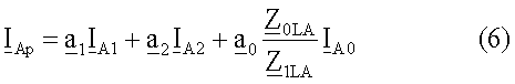
где:Where:
V A1, V A2, V A0 - напряжение, измеренное на станции A для отдельных симметричных составляющих, для положительной последовательной составляющей - индекс 1, для отрицательной последовательной составляющей - индекс 2 и для нулевой последовательной составляющей - индекс 0; V A1 , V A2 , V A0 - voltage measured at station A for individual symmetrical components, for a positive serial component -
I A1, I A2, I A0 - токи, измеренные на станции A для положительной последовательной составляющей - индекс 1, для отрицательной последовательной составляющей - индекс 2 и для нулевой последовательной составляющей - индекс 0; I A1 , I A2 , I A0 - currents measured at station A for the positive serial component -
Z 1LA - импеданс участка LA линии для положительной последовательной составляющей; Z 1LA is the impedance of the portion of the LA line for the positive serial component;
Z 0LA - импеданс участка LA линии для нулевой последовательной составляющей; Z 0LA is the impedance of the portion of the LA line for the zero serial component;
В частности, для повреждения типа a-b-g весовые коэффициенты будут:In particular, for damage of type a-b-g, weights will be:
![]()
![]()
![]()
![]()
![]()
![]()
Весовые коэффициенты для любых типов повреждений получаются в таблице 4.Weights for any type of damage are obtained in table 4.
Уравнение контура повреждения имеет следующую форму:The damage contour equation has the following form:
![]()
![]()
Когда уравнение (7) записывается отдельно для действительной части и для мнимой части, и выполняются дальнейшие математические преобразования, получают решение показанное ниже в пункте 3.2a.When equation (7) is written separately for the real part and for the imaginary part, and further mathematical transformations are performed, the solution shown in paragraph 3.2a below is obtained.
3.2a. Расстояние dA до точки повреждения и сопротивление RFA в месте повреждения определяют из следующих уравнений:3.2a. The distance d A to the point of damage and the resistance R FA at the site of damage is determined from the following equations:

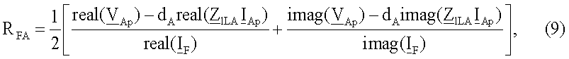
где:Where:
„real” обозначает действительную часть заданной величины;"Real" denotes the real part of a given value;
„imag” обозначает мнимую часть заданной величины;“Imag” means the imaginary part of a given quantity;
V Ap - обозначает напряжение на контуре повреждения согласно формуле (5); V Ap - denotes the voltage on the damage circuit according to the formula (5);
I F - обозначает полный ток повреждения согласно формуле (1); I F - indicates the total fault current according to the formula (1);
Z 1LA - обозначает импеданс участка LA линии для положительной последовательной составляющей; Z 1LA - indicates the impedance of the portion of the LA line for the positive serial component;
I Ap - обозначает контурный ток повреждения, определяемый согласно формуле (6). I Ap - denotes the loop fault current, determined according to the formula (6).
3.1.b. Напряжения для симметричных составляющих ![]()
![]()
![]()
![]()
![]()
![]()
![]()
![]()
![]()
![]()
![]()
![]()
где:Where:
γ 1LA - постоянная распространения участка LA линии для положительной и отрицательной последовательных составляющих; γ 1LA is the propagation constant of the LA line section for the positive and negative sequential components;
γ 0LA - постоянная распространения участка LA линии для нулевой последовательной составляющей; γ 0LA is the propagation constant of the portion of the LA line for the zero sequential component;
ℓLA - длина участка LA линии;ℓ LA is the length of the section of the LA line;
Z c1LA - волновое полное сопротивление участка LA линии для положительной и отрицательной последовательных составляющих; Z c1LA is the wave impedance of the portion of the LA line for the positive and negative sequential components;
Z c0LA - волновое полное сопротивление участка LA линии для нулевой последовательной составляющей. Z c0LA is the wave impedance of the portion of the LA line for the zero serial component.
3.2.b. Значения тока, входящего в точку ответвления T из участка LA линии: ![]()
![]()
![]()
![]()
![]()
![]()
![]()
![]()
![]()
![]()
![]()
![]()
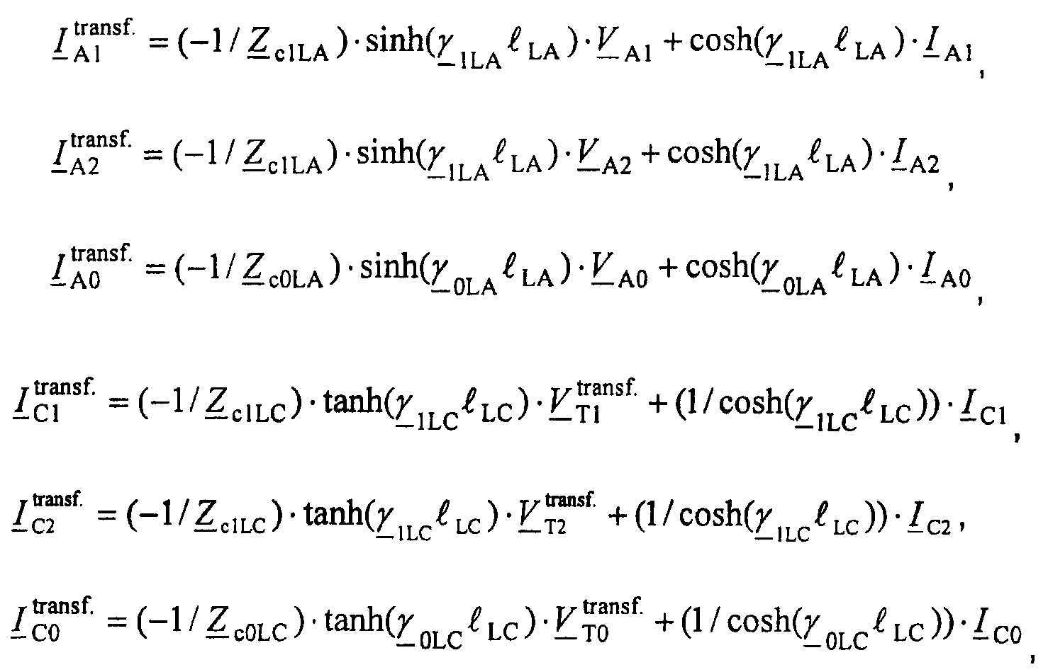
где:Where:
γ 1LC - постоянная распространения участка LC линии для положительной и отрицательной последовательных составляющих; γ 1LC is the propagation constant of the LC line section for positive and negative sequential components;
γ 0LC - постоянная распространения участка LC линии для нулевой последовательной составляющей; γ 0LC is the propagation constant of the LC line section for the zero sequential component;
Z c1LC - волновое полное сопротивление участка LC линии для положительной и отрицательной последовательных составляющих; Z c1LC - wave impedance of the LC line section for the positive and negative serial components;
Z c0LC - волновое полное сопротивление участка LC линии для нулевой последовательной составляющей; Z c0LC is the wave impedance of the LC line section for the zero serial component;
ℓLC - длина участка LC линии.ℓ LC is the length of the LC line section.
3.3.b. Значения тока ![]()
![]()
![]()
![]()
![]()
![]()
![]()
![]()
![]()
![]()
![]()
![]()
Уравнение контура повреждения имеет следующую форму:The damage contour equation has the following form:
![]()
![]()
где:Where:
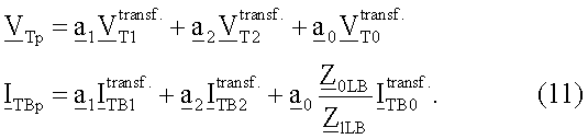
Когда уравнение (10) записывается отдельно для действительной части и для мнимой части и выполняются дальнейшие математические преобразования, получается решение, показанное под пунктом 3.4.b.When equation (10) is written separately for the real part and for the imaginary part and further mathematical transformations are performed, the solution shown in paragraph 3.4.b is obtained.
3.4.b. Расстояние dB до точки повреждения и сопротивление RFB в месте повреждения определяют из следующих уравнений:3.4.b. The distance d B to the point of damage and the resistance R FB at the site of damage is determined from the following equations:

где:Where:
Z 1LB - импеданс участка LB линии для положительной последовательной составляющей; Z 1LB is the impedance of the portion of the LB line for the positive serial component;
Z 1LB - импеданс участка LB линии для нулевой последовательной составляющей. Z 1LB is the impedance of the portion of the LB line for the zero serial component.
3.1.c. Значения тока, входящего в точку ответвления T из участка LA линии: ![]()
![]()
![]()
![]()
![]()
![]()
![]()
![]()
![]()
![]()
![]()
![]()
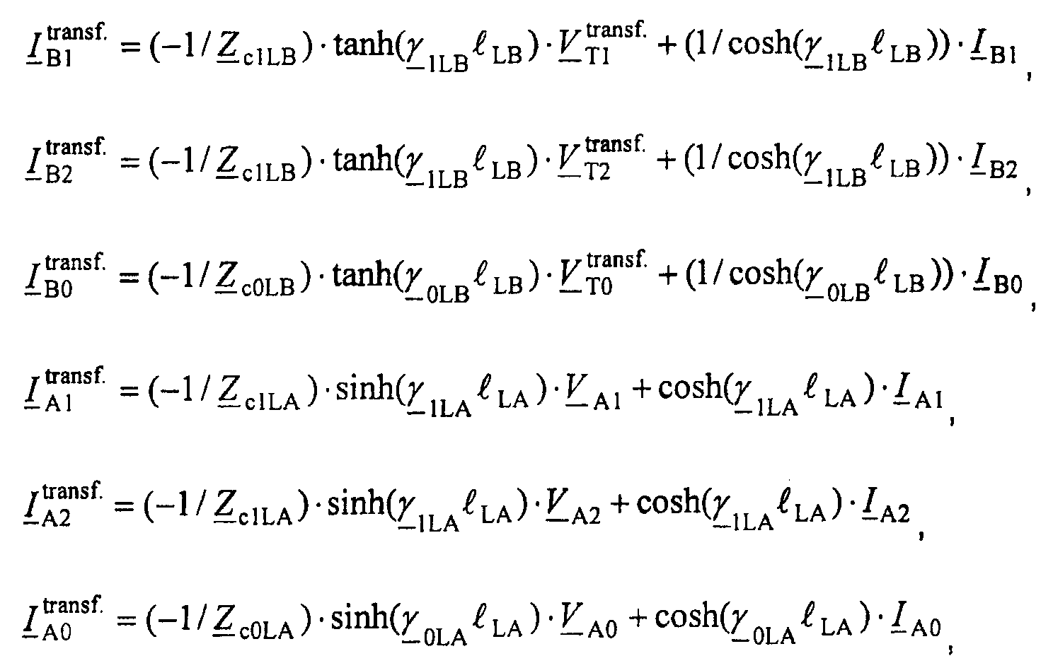
где:Where:
γ 1LB - постоянная распространения участка LB линии для положительной и отрицательной последовательных составляющих; γ 1LB is the propagation constant of the LB line section for positive and negative sequential components;
γ 0LB - постоянная распространения участка LB линии для нулевой последовательной составляющей; γ 0LB is the propagation constant of the LB line section for the zero sequential component;
ℓLB - длина участка LB линии;ℓ LB is the length of the section of the LB line;
Z c1LB - волновое полное сопротивление участка LB линии для положительной и отрицательной последовательных составляющих; Z c1LB is the wave impedance of the LB line section for positive and negative serial components;
Z c0LCB - волновое полное сопротивление участка LB линии для нулевой последовательной составляющей; Z c0LCB is the wave impedance of the LB line section for the zero serial component;
3.2.c. Значения тока ![]()
![]()
![]()
![]()
![]()
![]()
![]()
![]()
![]()
![]()
![]()
![]()
Уравнение контура повреждения имеет следующую форму:The damage contour equation has the following form:
![]()
![]()
где:Where:
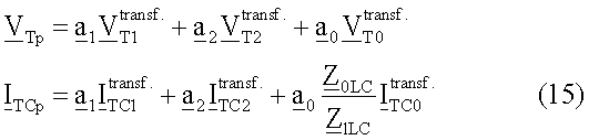
Когда уравнение (13) записывается отдельно для действительной части и для мнимой части и выполняются дальнейшие математические преобразования, получается решение, показанное под пунктом 3.3.c.When Eq. (13) is written separately for the real part and for the imaginary part and further mathematical transformations are performed, the solution shown in paragraph 3.3.c. is obtained.
3.3.c. Расстояние dC до точки повреждения и сопротивление RFC в месте повреждения определяют из следующих уравнений:3.3.c. The distance d C to the point of damage and the resistance R FC at the site of damage is determined from the following equations:
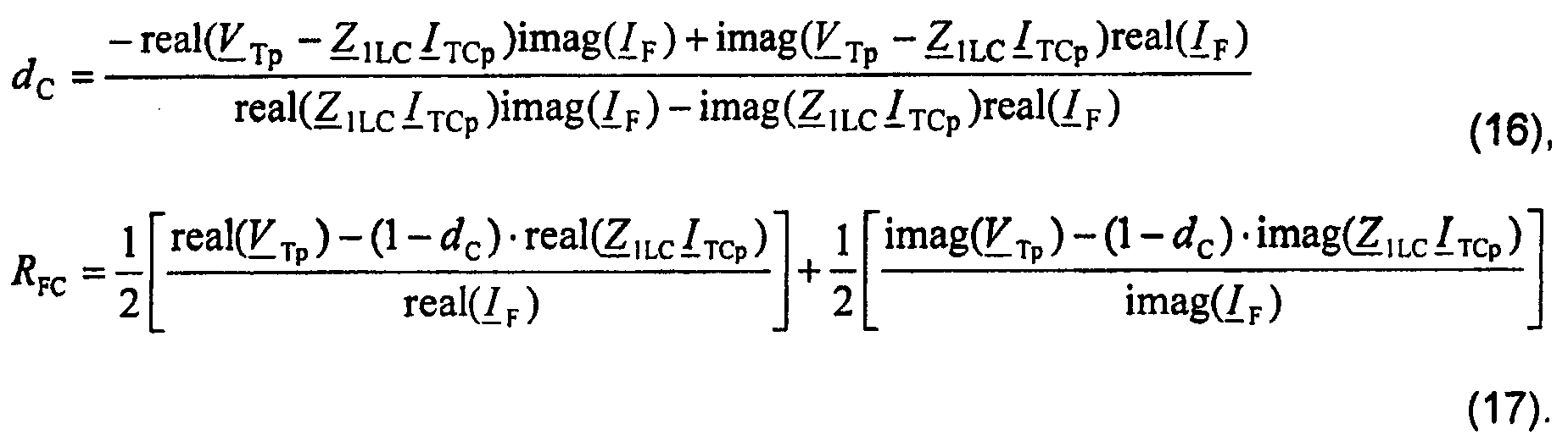
III. СТАДИЯ ТРИIII. STAGE THREE
На этой стадии, делают выбор окончательных результатов.At this stage, make a selection of the final results.
4. Проверяют, содержатся ли результаты вычисления расстояний dA, dB, dC до точки повреждения в заданном интервале (0-1) в относительных единицах:4. Check whether the results of calculating the distances d A , d B , d C to the point of damage in a given interval (0-1) in relative units:
0≤dA≤1,0≤d A ≤1,
0≤dB≤1,0≤d B ≤1,
0≤dC≤1.0≤d C ≤1.
Результаты, которые не содержатся в заданном интервале, показывают, что они были вычислены в ложном предварительном допущении относительно точки возникновения повреждения заданном участке линии. Эти результаты отбрасывают.Results that are not contained in the specified interval show that they were calculated in a false preliminary assumption regarding the point of occurrence of damage in a given section of the line. These results are discarded.
5. Анализируют второе вычисленное значение, то есть, сопротивление в месте повреждения RFA, RFB, RFC, и те результаты вычислений, для которых сопротивление в месте повреждения является отрицательным, отбрасывают.5. The second calculated value is analyzed, that is, the resistance at the fault location R FA , R FB , R FC , and those calculation results for which the resistance at the fault location is negative are discarded.
6. Если анализ критериев согласно действиям 4 и 5 не показывает явно, какие значения задают место повреждения, то в следующих действиях вычисляют импеданс системы эквивалентных источников для отрицательной последовательной составляющей в случае однофазных коротких замыканий на землю, междуфазных коротких замыканий, двухфазных коротких замыканий на землю, или альтернативно, для инкрементной положительной последовательной составляющей. Для трехфазных коротких замыканий вычисляют импеданс системы эквивалентных источников для инкрементной положительной последовательной составляющей.6. If the analysis of the criteria according to
7. Вычисляют ток I FA2 (фиг.11) в предположении, что повреждение произошло на участке LA линии:7. Calculate the current I FA2 (Fig.11) under the assumption that the damage occurred on the section of the LA line:
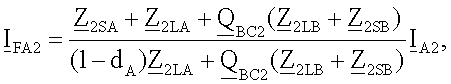
где:Where:
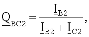
8. Вычисляют импеданс (Z 2SB)SUB_A)эквивалентных источников в предположении, что повреждение произошло на участке LA линии:8. The impedance ( Z 2SB ) SUB_A ) of the equivalent sources is calculated under the assumption that the damage occurred on the section of the LA line:
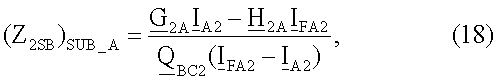
где:Where:
![]()
![]()
![]()
![]()

9. Вычисляют импеданс (Z 2SC)SUB_A)эквивалентных источников в предположении, что повреждение произошло на участке LA линии:9. The impedance ( Z 2SC ) SUB_A ) of the equivalent sources is calculated under the assumption that the damage occurred on the section of the LA line:
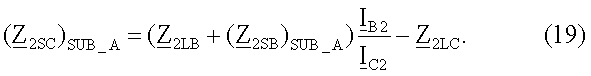
10. Вычисляют импеданс (Z 2SB)SUB_B)эквивалентных источников в предположении, что повреждение произошло на участке LB линии:10. The impedance ( Z 2SB ) SUB_B ) of equivalent sources is calculated under the assumption that the damage occurred on the LB line section:

11. Вычисляют импеданс (Z 2SC)SUB_B)эквивалентных источников в предположении, что повреждение произошло на участке LB линии:11. Calculate the impedance ( Z 2SC ) SUB_B ) of equivalent sources on the assumption that the damage occurred on the LB line section:

где:Where:
![]()
![]()
![]()
![]()
![]()
![]()
12. Вычисляют импеданс (Z 2SB)SUB_c)эквивалентных источников в предположении, что повреждение произошло на участке LC линии:12. Calculate the impedance ( Z 2SB ) SUB _ c ) of equivalent sources on the assumption that the damage occurred on the portion of the LC line:
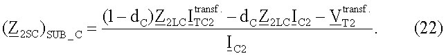
13. Вычисляют импеданс (Z 2SB)SUB_C)эквивалентных источников в предположении, что повреждение произошло на участке LC линии:13. The impedance ( Z 2SB ) SUB_C ) of equivalent sources is calculated under the assumption that the damage occurred on the LC line section:

где:Where:
![]()
![]()
14. Вычисленные импедансы эквивалентных источников преобразуют в модулярную форму, после чего выбирают правильный результат на основе модуля импедансов системы эквивалентных источников.14. The calculated impedances of the equivalent sources are converted into a modular form, after which the correct result is selected based on the impedances module of the system of equivalent sources.
Если значение модуля импедансов системы эквивалентных источников, вычисленное в предположении возникновения повреждения на заданном участке линии, не соответствует действительному значению модуля импедансов системы эквивалентных источников, то это означает, что предварительные данные, касающиеся места возникновения повреждения на заданном участке, были приняты неправильно, и результат вычисления расстояния до точки повреждения, полученный в этом предположении, отбрасывают.If the value of the impedance module of the system of equivalent sources, calculated under the assumption of damage on the specified section of the line, does not correspond to the actual value of the impedance module of the system of equivalent sources, this means that the preliminary data regarding the location of the damage on the specified section were incorrectly received, and the result the distance calculation to the damage point obtained under this assumption is discarded.
Временная последовательность действий, показанная на фиг.13, включает в себя следующие действия для осуществления настоящего изобретения:The time sequence of operations shown in FIG. 13 includes the following actions for implementing the present invention:
- измеряют ток и напряжение согласно п.1 примера варианта осуществления изобретения,- measure the current and voltage according to
- определяют симметричные составляющие измеренных токов и напряжений и вычисляют полный ток повреждения согласно п.2 примера варианта осуществления изобретения,- determine the symmetrical components of the measured currents and voltages and calculate the total fault current according to
- вычисляют три гипотетических расстояния до точек повреждения и трех сопротивлений в местах повреждения, в предположении, что повреждение произошло на участке LA, на участке LB и на участке LC, согласно п.п.3.1.a-3.2.a, 3.1.b-3.4.b, 3.1.c-3.3.c примера варианта осуществления изобретения,- calculate three hypothetical distances to the points of damage and three resistances at the places of damage, under the assumption that the damage occurred in section LA, in section LB and in section LC, according to clauses 3.1.a-3.2.a, 3.1.b- 3.4.b, 3.1.c-3.3.c of an example embodiment of the invention,
- проверяют, находятся ли конкретные гипотетические расстояния в интервале от 0 до 1 в относительных единицах, и отбрасывают гипотетические расстояния, значения которых являются отрицательными или больше 1, согласно п.4 примера варианта осуществления изобретения,- check whether specific hypothetical distances are in the range from 0 to 1 in relative units, and discard hypothetical distances whose values are negative or greater than 1, according to
- проверяют, являются ли значения сопротивления в месте повреждения больше или равными нулю, и отбрасывают значения меньше нуля, согласно п.5 примера варианта осуществления изобретения,- check whether the resistance values at the damage site are greater than or equal to zero, and values less than zero are discarded, according to claim 5 of an example embodiment of the invention,
- вычисляют импеданс эквивалентных источников отдельных участков, в предположении, что повреждение произошло на заданном участке, согласно п.п.8-13 примера варианта осуществления изобретения,- calculate the impedance of the equivalent sources of individual sections, under the assumption that the damage occurred on a given section, according to PP 8-13 of an example embodiment of the invention,
- выбирают правильный результат, согласно п.14 примера варианта осуществления изобретения.- choose the correct result, according to paragraph 14 of an example embodiment of the invention.
Описанный пример применим к двухфазному короткому замыканию на землю типа (a-b-g). Однако этот способ является аналогичным для других типов повреждений. Если анализируют другие типы повреждений, соответствующие коэффициенты a F1, a F2, a F0, a 1, a 2, a 0 изменяют. Значения этих коэффициентов получают в таблицах 1-4. Способ определения места повреждения в трехтерминальных линиях электропередачи согласно настоящему изобретению охватывает также другие типы повреждений, то есть a-g, b-g, c-g, a-b, b-c, c-a, b-c-g, c-a-g, a-b-c, a-b-c-g.The described example is applicable to a two-phase earth fault type (abg). However, this method is similar for other types of damage. If other types of damage are analyzed, the corresponding coefficients a F1 , a F2 , a F0, a 1 , a 2 , a 0 are changed. The values of these coefficients are obtained in tables 1-4. The method for determining the location of damage in the three-terminal power lines according to the present invention also covers other types of damage, that is, ag, bg, cg, ab, bc, ca, bcg, cag, abc, abcg.
Предложенный способ не ограничивается моделью одной линии, представленной в примере анализа, но также может применяться к другой модели (не показана), в которой предполагается присутствие ряда компенсирующих конденсаторов на участке линии с повреждением. В этом случае уравнения (6), (11), (15), применимые к контурному току повреждения, будут модифицироваться из-за существования упомянутых конденсаторов.The proposed method is not limited to the model of one line presented in the analysis example, but can also be applied to another model (not shown), in which the presence of a number of compensating capacitors in the section of the line with damage is assumed. In this case, equations (6), (11), (15), applicable to the loop fault current, will be modified due to the existence of the mentioned capacitors.
В предложенном способе используются синхронные измерения токов в трех станциях системы электропередачи или распределительной системы, дополнительно используется измерение напряжения на станции, где установлен прибор для обнаружения мест повреждения. Такая доступность входных сигналов не рассматривается в других решениях, которые используются в настоящее время.In the proposed method, synchronous current measurements are used in three stations of the power transmission system or distribution system, and voltage measurement is additionally used at the station where the device for detecting damage points is installed. Such availability of input signals is not considered in other solutions that are currently used.
Выбор обоснованного результата основан на объединении трех количественных критериев: расстояния до точки повреждения, сопротивления в месте повреждения и модуля импеданса систем эквивалентных источников для тех станций, где не измеряется напряжение. Третий критерий является инновационным, и до сих пор не был известен.The choice of a substantiated result is based on a combination of three quantitative criteria: distance to the point of damage, resistance at the place of damage, and impedance module of systems of equivalent sources for those stations where voltage is not measured. The third criterion is innovative, and has not yet been known.
ПРИМЕР ВАРИАНТА ОСУЩЕСТВЛЕНИЯ ИЗОБРЕТЕНИЯ ДЛЯ МНОГОТЕРМИНАЛЬНОЙ ЛИНИИ ЭЛЕКТРОПЕРЕДАЧИEXAMPLE OF EMBODIMENTS OF THE INVENTION FOR A MULTI-TERM ELECTRIC TRANSMISSION LINE
Система электропередачи или распределительная система, показанная на фиг.14, состоит из электростанций 1, 2, …, n. Станция 1 расположена в начале линии, nая станция на конце этой линии. Точки ответвления T1, T2, … T(n-1) делят систему электропередачи на участки линии L1, L2, …, L(2n-3). На станции 1 имеется прибор для обнаружения мест повреждения FL. Определение места повреждения выполняют с использованием моделей повреждений и контуров повреждений для симметричных составляющих и с учетом различных типов повреждений в одно и то же время, посредством применения подходящих распределенных коэффициентов, определяющих соотношение между симметричными составляющими полного тока повреждения, когда оценивают падение напряжения на сопротивлении в местах повреждения, задаваемых как a F1, a F2, a F0, и весовых коэффициентов a 1, a 2, a 0, задающих долю отдельных составляющих в полной модели контура повреждения. Анализ граничных условий для различных типов повреждений показывает наличие некоторой степени свободы при определении распределенных коэффициентов, определяющих соотношение между симметричными составляющими полного тока повреждения, когда оценивается падение напряжения на сопротивлении в месте повреждения. Их выбор зависит от принятого предпочтения использования отдельных последовательных составляющих, в зависимости от типа повреждения. В описываемом примере варианта осуществления изобретения, чтобы гарантировать высокую точность определения места повреждения, падение напряжения на сопротивлении в месте повреждения оценивают с использованием:The power transmission system or distribution system shown in Fig. 14 consists of
- отрицательной составляющей полного тока повреждения для однофазных коротких замыканий на землю (a-g), (b-g), (c-g) и междуфазных коротких замыканий (a-b), (b-c) и (c-a);- the negative component of the total fault current for single-phase earth faults (a-g), (b-g), (c-g) and interphase short-circuits (a-b), (b-c) and (c-a);
- отрицательной составляющей и нулевой последовательной составляющей для двухфазных коротких замыканий на землю (a-b-g), (b-c-g), (c-a-g);- negative component and zero serial component for two-phase earth faults (a-b-g), (b-c-g), (c-a-g);
- инкрементной положительной последовательной составляющей для трехфазных коротких замыканий (a-b-c, a-b-c-g), для которых значение повреждения уменьшают на значение перед повреждением положительной последовательной составляющей тока.- an incremental positive serial component for three-phase short circuits (a-b-c, a-b-c-g), for which the damage value is reduced by the value before the positive serial component of the current is damaged.
Рекомендуемые распределенные коэффициенты, определяющие соотношение между симметричными составляющими полного тока повреждения, когда оценивают падение напряжения на сопротивлении в месте повреждения, представлены в таблице 5. Тип повреждения обозначен символами: a-g, b-g, c-g, a-b, b-c, c-a, a-b-g, b-c-g, c-a-g, a-b-c, a-b-c-g, где буквы a, b, c обозначают отдельные фазы тока, и буква g обозначает заземление (землю), индекс 1 обозначает положительную последовательную составляющую, индекс 2 - отрицательную составляющую и индекс 0 - нулевую последовательную составляющую.Recommended distributed coefficients that determine the relationship between the symmetrical components of the total fault current when evaluating the voltage drop across the resistance at the fault location are presented in Table 5. The type of damage is indicated by the symbols: ag, bg, cg, ab, bc, ca, abg, bcg, cag , abc, abcg, where the letters a, b, c denote the individual phases of the current, and the letter g denotes the ground (ground),
![]()
![]()
![]()
![]()
![]()
![]()
![]()
![]()
![]()
![]()
![]()
![]()
![]()
![]()
![]()
![]()
![]()
![]()
![]()
![]()
![]()
![]()
а-b-с-ga-b-c
a-b-c-g
![]()
![]()
![]()
![]()
В таблице 6 получают распределенные коэффициенты отдельных составляющих тока a 1, a 2, a 0, задающие долю отдельных составляющих в полной модели контура повреждения.Table 6 gives the distributed coefficients of the individual components of the current a 1 , a 2 , a 0 specifying the proportion of the individual components in the full model of the damage circuit.
![]()
![]()
![]()
![]()
![]()
![]()
![]()
![]()
a-b-c, a-b-c-gab, abg
abc, ![]()
![]()
![]()
![]()
![]()
![]()
![]()
![]()
![]()
![]()
![]()
![]()
Синхронные измерения фазных токов из оконечных станций 1, 2, …, n и фазового напряжения только из станции 1 подают в прибор для обнаружения мест повреждения FL. Дополнительно, предполагается, что информация о типе повреждения и времени его происхождения подается в прибор для обнаружения мест повреждения. Процесс определения места повреждения, в предположении, что это повреждение типа (a-b-g) - междуфазное короткое замыкание на землю, следующий:Synchronous measurements of the phase currents from the
I'. СТАДИЯ ОДИН'I '. STAGE ONE '
1'. Операция 610. На станциях 1, 2, …, n измеряют входные сигналы тока из отдельных линий для условия повреждения и условия перед повреждением. На станции 1 измеряют фазовые напряжения линии для условия повреждения и условия перед повреждением. Затем, вычисляют симметричные составляющие фазных токов, измеренных на станциях 1, 2, …, n, и фазовых напряжений, измеренных на станции 1.one'.
2'. Операция 620. Полный ток повреждения (I F) вычисляют из следующего уравнения:2 '.
![]()
![]()
где:Where:
первый нижний индекс „F” обозначает условие повреждения; второй нижний индекс обозначает: „1” - положительную последовательную составляющую; „2” - отрицательную последовательную составляющую; „0” - нулевую последовательную составляющую;the first subscript “F” indicates the condition of the damage; the second subscript indicates: “1” - positive sequential component; “2” - negative sequential component; “0” - zero sequential component;
a F1, a F2, a F0 - коэффициенты, представленные в Таблице 2. a F1 , a F2 , a F0 are the coefficients presented in Table 2.
Симметричные составляющие полного тока повреждения определяют как сумму отдельных симметричных составляющих токов, определяемых в оконечных станциях 1, 2, …, n:Symmetric components of the total fault current are defined as the sum of the individual symmetrical components of the currents defined in
![]()
![]()
![]()
![]()
![]()
![]()
где: первый нижний индекс обозначает станцию, второй нижний индекс обозначает: 1 - положительную последовательную составляющую, 2 - отрицательную последовательную составляющую, 0 - обозначает нулевую последовательную составляющую.where: the first subscript denotes the station, the second subscript denotes: 1 - positive sequential component, 2 - negative sequential component, 0 - indicates zero sequential component.
II'. СТАДИЯ ДВА'II '. STAGE TWO '
1. На стадии два', принимают гипотетическую точку повреждения и вычисляют расстояние между концом заданной линии и гипотетической точкой повреждения (действия выполняют в операциях 630a, 630b, 630c, 630d) при следующих допущениях:1. At stage two ', take a hypothetical point of damage and calculate the distance between the end of a given line and a hypothetical point of damage (actions are performed in
- вычисление расстояния от начала линии до точки повреждения, в предположении, что повреждение произошло на участке L1 линии - действия 3.1.a';- calculation of the distance from the beginning of the line to the point of damage, on the assumption that the damage occurred on the section L1 of the line - action 3.1.a ';
- вычисление расстояния от конца линии до точки повреждения, в предположении, что повреждение произошло на оконечном участке L(2n-3) линии - действия 3.1.b'-3.3.b';- calculation of the distance from the end of the line to the point of damage, on the assumption that the damage occurred at the terminal portion L (2n-3) of the line - actions 3.1.b'-3.3.b ';
- вычисление расстояния от конца линии передачи с ответвлениями до точки повреждения, в предположении, что повреждение расположено на kом участке линии передачи с ответвлениями - действия 3.1.c'-3.2.c';- calculation of the distance from the end of the transmission line with branches to a point of damage, on the assumption that the fault is located on the k th portion of a transmission line with taps - Actions 3.1.c'-3.2.c ';
- вычисление расстояния от точки ответвления T(k) до точки повреждения, в предположении, что повреждение расположено на участке линии между двумя точками ответвления - действия 3.1.d'-3.3d'.- calculation of the distance from the branch point T (k) to the damage point, assuming that the damage is located on the line segment between the two branch points - steps 3.1.d'-3.3d '.
3.1.a'. Напряжение и ток на контуре повреждения определяют из следующих соотношений между симметричными составляющими (фиг.2-4) (действия выполняют в операциях 630a):3.1.a '. The voltage and current on the damage circuit is determined from the following relationships between the symmetrical components (FIGS. 2-4) (actions are performed in
![]()
![]()
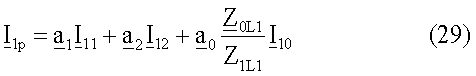
где:Where:
V 11, V 12, V 10 - напряжение, измеренное на станции 1 (первый нижний индекс) для отдельных симметричных составляющих, а второй нижний индекс для положительной последовательной составляющей будет равен 1, для отрицательной последовательной составляющей будет равен 2, и для нулевой последовательной составляющей будет равен 0; V 11 , V 12 , V 10 is the voltage measured at station 1 (first subscript) for individual symmetrical components, and the second subscript for a positive sequential component will be 1, for a negative serial component it will be 2, and for a zero serial component will be equal to 0;
I 11, I 12, I 10 - токи, измеренные на станции 1 (первый нижний индекс) для отдельных симметричных составляющих, а второй нижний индекс для положительной последовательной составляющей будет равен 1, для отрицательной последовательной составляющей будет равен 2, и для нулевой последовательной составляющей будет равен 0; I 11 , I 12 , I 10 are the currents measured at station 1 (first subscript) for individual symmetrical components, and the second subscript for a positive sequential component will be 1, for a negative serial component it will be 2, and for a zero serial component will be equal to 0;
Z 1L1 - импеданс участка L1 линии для положительной последовательной составляющей; Z 1L1 is the impedance of the line section L1 for the positive serial component;
Z 0L1 - импеданс участка L1 линии для нулевой последовательной составляющей; Z 0L1 is the impedance of the line section L1 for the zero serial component;
a 1, a 2, a 0 - весовые коэффициенты получают в таблице 2. a 1 , a 2 , a 0 - weighting coefficients are obtained in table 2.
Уравнение контура повреждения имеет следующую форму:The damage contour equation has the following form:
![]()
![]()
Уравнение (30) записывают отдельно для действительной части и для мнимой части, и выполняют дальнейшие математические преобразования, получают уравнения для искомого расстояния до точки повреждения (31) и для сопротивления в месте повреждения (32).Equation (30) is written separately for the real part and for the imaginary part, and further mathematical transformations are performed, equations are obtained for the desired distance to the damage point (31) and for the resistance at the damage site (32).


где:Where:
„real” обозначает действительную часть заданной комплексной величины;“Real” denotes the real part of a given complex quantity;
„imag” обозначает мнимую часть заданной комплексной величины;“Imag” denotes the imaginary part of a given complex quantity;
V 1p - обозначает напряжение на контуре повреждения согласно формуле (28); V 1p - indicates the voltage on the damage circuit according to the formula (28);
I F - обозначает полный ток повреждения согласно формуле (25); I F - indicates the total fault current according to the formula (25);
Z 1L1 - обозначает импеданс участка L1 линии для положительной последовательной составляющей; Z 1L1 - denotes the impedance of the line section L1 for the positive serial component;
I 1p - обозначает контурный ток повреждения, определяемый согласно формуле (29). I 1p - indicates the loop fault current, determined according to the formula (29).
3.1.b'. Вычисляют напряжения для симметричных составляющих ![]()
![]()
![]()
![]()
![]()
![]()
![]()
![]()
где:Where:
Z iL1 - импеданс участка L1 соответственно для положительной и отрицательной составляющих и также для нулевой последовательной составляющей. Z iL1 is the impedance of the section L1, respectively, for the positive and negative components and also for the zero sequential component.
3.2.b'. Вычисляют напряжения для симметричных составляющих ![]()
![]()
![]()
![]()
![]()
![]()

где:Where:
Z iL(2n-3)- импеданс участка L(2n-3) линии соответственно для положительной и отрицательной составляющих и также для нулевой последовательной составляющей. Z iL (2n-3) is the impedance of the portion of the L (2n-3) line, respectively, for the positive and negative components and also for the zero sequential component.
В то же время напряжения ![]()
![]()
![]()
![]()
![]()
![]()

где:Where:
![]()
![]()
Z iL(2k-3) - импеданс участка L(2k-3) линии для симметричных составляющих. Z iL (2k-3) is the impedance of the portion of the L (2k-3) line for the symmetrical components.
3.3.b'. Вычисляют значения тока ![]()
![]()
![]()
![]()
![]()
![]()

Уравнение контура повреждения имеет следующую форму:The damage contour equation has the following form:

Уравнение (37) записывают отдельно для действительной части и для мнимой части и выполняют дальнейшие математические преобразования, получают решения (38) для искомого расстояния d(2n-3) до точки повреждения и для сопротивления R(2n-3)B в месте повреждения:Equation (37) is written separately for the real part and for the imaginary part and further mathematical transformations are performed, solutions (38) are obtained for the desired distance d (2n-3) to the damage point and for the resistance R (2n-3) B at the damage location:

где:Where:
Z 1L(2n-3) - импеданс участка L(2n-3) линии для положительной последовательной составляющей; Z 1L (2n-3) is the impedance of the portion of the L (2n-3) line for the positive serial component;
Z 0L(2n-3)- импеданс участка L(2n-3) линии для нулевой последовательной составляющей. Z 0L (2n-3) is the impedance of the portion of the L (2n-3) line for the zero sequential component.
3.1.c'. Напряжения ![]()
![]()
![]()
![]()
![]()
![]()
3.2.c'. Вычисляют значения тока ![]()
![]()
![]()
![]()
![]()
![]()

Уравнение контура повреждения имеет следующую форму:The damage contour equation has the following form:
![]()
![]()
где:Where:
![]()
![]()

Уравнение (40) записывают отдельно для действительной части и для мнимой части, и выполняют дальнейшие математические преобразования, получают решения (42) для искомого расстояния d(2k-3) и до точки повреждения и (43) для сопротивления R(2k-3)B в месте повреждения:Equation (40) is written separately for the real part and for the imaginary part, and further mathematical transformations are performed, solutions (42) are obtained for the desired distance d (2k-3) and to the damage point and (43) for the resistance R (2k-3) B at the place of damage:

где:Where:
Z 1L(2k-2) - импеданс участка L(2k-2) линии для положительной последовательной составляющей; Z 1L (2k-2) is the impedance of the portion of the L (2k-2) line for the positive serial component;
Z 0L(2k-2) - импеданс участка L(2k-2) линии для нулевой последовательной составляющей. Z 0L (2k-2) is the impedance of the portion of the L (2k-2) line for the zero sequential component.
3.1.d'. Напряжения ![]()
![]()
![]()
![]()
![]()
![]()
3.2.d'. Вычисляют значения тока ![]()
![]()
![]()
![]()
![]()
![]()

Уравнение контура повреждения имеет следующую форму:The damage contour equation has the following form:
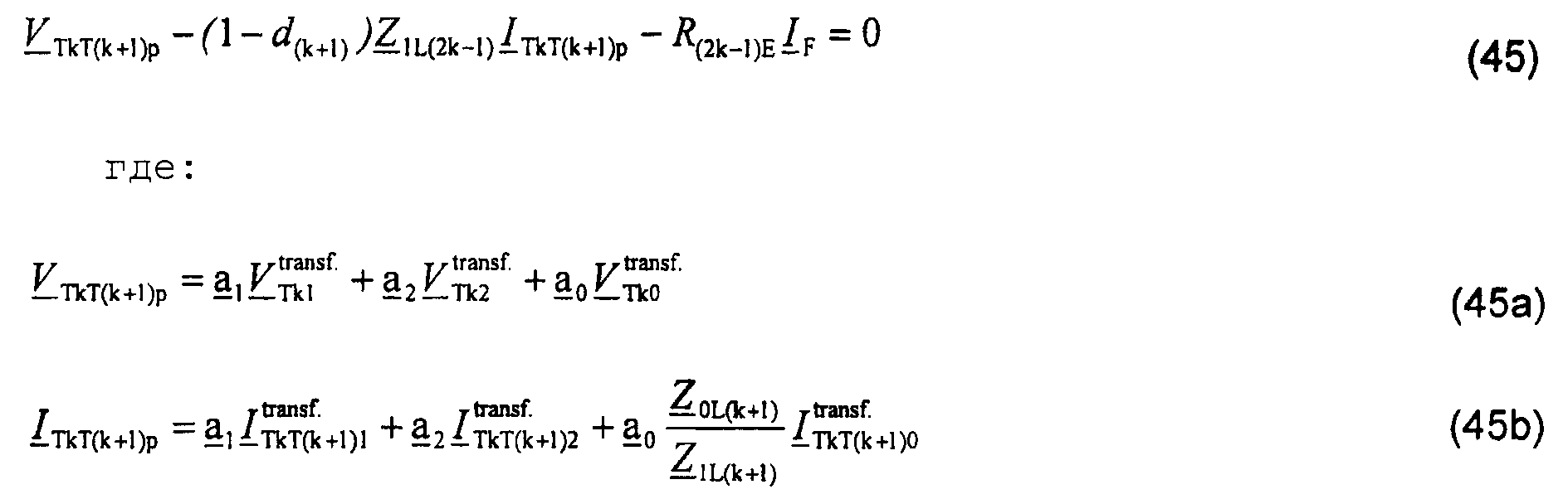
Уравнение (45) записывается отдельно для действительной части и для мнимой части и выполняют дальнейшие математические преобразования, получают решения (46) для искомого расстояния d(2k-1) до точки повреждения и (47) для сопротивления R(2k-1)F в месте повреждения:Equation (45) is written separately for the real part and for the imaginary part and further mathematical transformations are performed, solutions (46) are obtained for the desired distance d (2k-1) to the damage point and (47) for the resistance R (2k-1) F in place of damage:

где:Where:
Z 1L(2k-1) - импеданс участка L(2k-1) линии для положительной последовательной составляющей; Z 1L (2k-1) is the impedance of the portion of the L (2k-1) line for the positive serial component;
Z 0L(2k-1) - импеданс участка L(2k-1) линии для нулевой последовательной составляющей. Z 0L (2k-1) is the impedance of the portion of the L (2k-1) line for the zero sequential component.
III'. СТАДИЯ ТРИ'III '. STAGE THREE '
На этой стадии делают выбор окончательных результатов (действия выполняют в операциях 640a, 640b, 640c, 640d).At this stage, the final results are selected (actions are performed in
4'. Проверяют, находятся ли результаты вычисления расстояний d1, d(2n-3), d(2k-2), d(2k-1) до точки повреждения в заданном интервале (0-1) в относительных единицах:four'. Check whether the results of calculating the distances d 1 , d (2n-3) , d (2k-2) , d (2k-1) to the point of damage in the specified interval (0-1) in relative units:
0≤d1≤1, 0≤d(2n-3)≤1, 0≤d(2k-2)≤1, 0≤d(2k-1)≤1, и проверяют, являются ли результаты вычисления сопротивлений R1F, R(2n-3)F, R(2k-2)F, R(2k-1)F в месте повреждения для вычисленных точек повреждения d1, d(2n-3), d(2k-2), d(2k-1) большими или равными нулю. Пары результатов: сопротивление - расстояние, например: d1, R1F, которые не содержатся в заданных интервалах, показывают, что они были вычислены в ложном предварительном допущении относительно точки возникновения повреждения в заданном участке линии. Эти результаты отбрасывают. Другие результаты подвергают дальнейшей обработке, за исключением случая, когда в заданном интервале находится только одна пара. Указанные результаты являются окончательными, то есть они показывают местоположение повреждения и сопротивление в месте повреждения (операция 650).0≤d 1 ≤1, 0≤d (2n-3) ≤1, 0≤d (2k-2) ≤1, 0≤d (2k-1) ≤1, and check if the results of calculating the resistances R 1F , R (2n-3) F , R (2k-2) F , R (2k-1) F at the fault location for the calculated damage points d 1 , d (2n-3) , d (2k-2) , d ( 2k-1) greater than or equal to zero. Pairs of results: resistance - distance, for example: d 1 , R 1F , which are not contained in given intervals, show that they were calculated in a false preliminary assumption regarding the point of occurrence of damage in a given section of the line. These results are discarded. Other results are further processed, except when only one pair is in a given interval. The indicated results are final, that is, they show the location of the damage and the resistance at the location of the damage (operation 650).
5'. Если анализ критериев, выполняемый согласно действиям 4', не обеспечивает точного заключения о том, какие значения задают местоположение повреждения и сопротивление в месте повреждения, то в следующих действиях, вычисляют импеданс эквивалентных источников для отрицательной составляющей для этих повреждений: однофазных коротких замыканий на землю, междуфазных коротких замыканий, двухфазных коротких замыканий на землю, или альтернативно, для инкрементной положительной последовательной составляющей. Для трехфазных коротких замыканий, вычисляют импеданс систем эквивалентных источников для инкрементной положительной последовательной составляющей. (Действия выполняют в операциях 660a, 660b, 660c, 660d).5'. If the analysis of the criteria, performed according to steps 4 ', does not provide an accurate conclusion about what values determine the location of the damage and the resistance at the location of the damage, then in the following steps, the impedance of equivalent sources for the negative component for these damage is calculated: single-phase earth faults, interphase short circuits, two-phase earth faults, or alternatively, for an incremental positive series component. For three-phase short circuits, the impedance of systems of equivalent sources is calculated for the incremental positive series component. (Actions are performed in
7'. Вычисляют полный ток повреждения I F2 для отрицательной последовательной составляющей из следующей формулы (действия выполняют в операциях 660a):7 '. The total fault current I F2 for the negative serial component is calculated from the following formula (actions are performed in

8'. Вычисляют импеданс Z 2S1 эквивалентных источников в предположении, что повреждение произошло на участке L1 (действия выполняются в операциях 660a):8'. The impedance Z 2S1 of the equivalent sources is calculated under the assumption that the damage occurred in the L1 region (actions are performed in

9'. Вычисляют импеданс Z 2Sn эквивалентных источников в предположении, что повреждение произошло на последнем участке L(2n-3) линии (действия выполняют в операциях 660b):9'. The impedance Z 2Sn of equivalent sources is calculated under the assumption that the damage occurred on the last section of the L (2n-3) line (actions are performed in

где:Where:
![]()
![]()
10'. Вычисляют импеданс Z 2Sk kого эквивалентного источника в предположении, что повреждение произошло на участке L(2k-2) линии передачи с ответвлениями (действия выполняют в операциях 660c):10'. Calculated impedance Z 2Sk k th equivalent source, assuming that the fault occurred on the portion L (2k-2) of the transmission line with taps (steps 660c operate in operations):

где:Where:
![]()
![]()
11'. Вычисляют импеданс (Z 2Sk) и (Z 2S(k+1)) эквивалентных источников в предположении, что повреждение расположено на участке линии между двумя точками ответвления Tk-T(k+1) (действия выполняют в операциях 660d):eleven'. The impedance ( Z 2Sk ) and ( Z 2S (k + 1) ) of equivalent sources are calculated under the assumption that the damage is located on the line segment between the two branch points Tk-T (k + 1) (actions are performed in

где:Where:
![]()
![]()
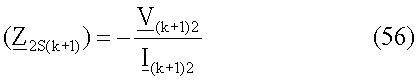
где:Where:
![]()
![]()
12'. Проверяют (действия выполняют в операциях 670a, 670b, 670c, 670d), содержатся ли импедансы (Z 2S1), (Z 2Sn), (Z 2SC)SUB_C, (Z 2Sk), (Z 2S(k+1)) эквивалентных источников в интервале в первом квадранте комплексной плоскости Z, то есть, являются ли как действительная, так и мнимая части вычисленного импеданса больше нуля. Импеданс систем эквивалентных источников определяют для отрицательной составляющей для возникновения повреждений: однофазных коротких замыканий на землю, междуфазных коротких замыканий, двухфазных коротких замыканий на землю, или альтернативно, для инкрементной положительной последовательной составляющей. Для трехфазных коротких замыканий вычисляют импеданс систем эквивалентных источников для инкрементной положительной последовательной составляющей.12'. Check (actions are performed in
Результаты, которые не содержатся внутри первого квадранта, дают основания предполагать, что они вычислялись на ложном предварительном допущении, касающемся местоположения повреждения на заданном участке линии, и результат вычисления расстояния до точки повреждения, сделанный на указанном предположении, отбрасывают. Остальные результаты подвергают дальнейшей обработке, за исключением случая, когда в первом квадранте содержится только один импеданс, вычисленный в предположении, что повреждение произошло на заданном участке линии. Результат вычисления расстояния до точки повреждения для указанного импеданса указывает на правильное предварительное допущение. Этот результат считают окончательным (действия, выполняют в операции 680).Results that are not contained within the first quadrant give reason to believe that they were calculated on a false preliminary assumption regarding the location of the damage in a given section of the line, and the result of calculating the distance to the damage point made on this assumption is discarded. The remaining results are further processed, except when the first quadrant contains only one impedance calculated on the assumption that the damage occurred on a given section of the line. The result of calculating the distance to the fault point for the indicated impedance indicates the correct preliminary assumption. This result is considered final (actions performed in operation 680).
13'. Если анализ критериев, выполняемый согласно действиям 12', не обеспечивает точного заключения о том, какие значения задают местоположение повреждения, то в следующих действиях (действия, выполняемые в операции 690a, 690b, 690c, 690d), вычисленные импедансы эквивалентных источников преобразуют в модулярную форму, после чего правильный результат выбирают на основе модуля импеданса эквивалентных источников.13'. If the analysis of the criteria performed according to steps 12 'does not provide an accurate conclusion about which values determine the location of the damage, then in the following steps (the actions performed in
14'. Операция 700. Если вычисленное значение модуля импеданса системы эквивалентных источников, в предположении возникновения повреждения на заданном участке линии, не соответствует действительному значению модуля импеданса системы эквивалентных источников, то это означает, что предварительные данные, касающиеся местоположения повреждения на заданном участке, были приняты ложно, и результат вычисления расстояния до точки повреждения, основанный на этом допущении, отбрасывают. Если вычисленное значение модуля импеданса системы эквивалентных источников, в предположении возникновения повреждения на заданном участке линии, соответствует действительному значению модуля импеданса системы источников, то результат вычисления расстояния до точки повреждения подтверждает правильное предварительное допущение, и этот результат считают окончательным.fourteen'.
Временная последовательность действий, показанная на фиг.19, включает в себя следующие действия для осуществления настоящего изобретения:The time sequence of operations shown in FIG. 19 includes the following actions for implementing the present invention:
- измерение токов и напряжений согласно п.1' примера варианта осуществления изобретения,- measurement of currents and voltages according to claim 1 'of an example embodiment of the invention,
- определение симметричных составляющих измеренных токов и напряжений и вычисление полного тока повреждения согласно п.2' примера варианта осуществления изобретения,- determining the symmetrical components of the measured currents and voltages and calculating the total fault current according to claim 2 'of an example embodiment of the invention,
- вычисление следующих друг за другом гипотетических расстояний до точек повреждения и сопротивлений в местах повреждения, в предположении, что повреждение расположено на первом участке L1 линии, на оконечном участке L(2n-3) линии, на участках (2k-2) линий передачи с ответвлениями и на участках между следующими друг за другом точками ответвления (2k-1), согласно пунктам 3.1.a'-3.2.a', 3.1.b'-3.4.b', 3.1.c'-3.3.c', 3.1.d'-3.3.d' примера варианта осуществления изобретения,- calculation of consecutive hypothetical distances to the points of damage and resistances at the places of damage, under the assumption that the damage is located on the first section of the L1 line, on the terminal section of the L (2n-3) line, on sections (2k-2) of the transmission lines with branches and in areas between successive branch points (2k-1), according to paragraphs 3.1.a'-3.2.a ', 3.1.b'-3.4.b', 3.1.c'-3.3.c ', 3.1 .d'-3.3.d 'of an example embodiment of the invention,
- проверку того, заключаются ли конкретные гипотетические расстояния, находящиеся в интервале от 0 до 1 в относительных единицах, и отбрасывание тех гипотетических расстояний, значения которых являются отрицательными или больше 1, согласно п.4' примера варианта осуществления изобретения,- checking whether specific hypothetical distances are in the range from 0 to 1 in relative units, and discarding those hypothetical distances whose values are negative or greater than 1, according to claim 4 'of an example embodiment of the invention,
- проверку того, являются ли значения сопротивления в месте повреждения больше или равными нулю, и отбрасывание значений меньше нуля, согласно п.5' примера варианта осуществления изобретения,- checking whether the resistance values at the fault location are greater than or equal to zero, and dropping the values less than zero, according to claim 5 'of an example embodiment of the invention,
- вычисление импеданса эквивалентных источников отдельных участков, в предположении, что повреждение расположено на заданном участке, согласно п.п.8'-11' примера варианта осуществления изобретения,- calculating the impedance of the equivalent sources of individual sections, under the assumption that the damage is located on a given section, according to paragraphs 8'-11 'of an example embodiment of the invention,
- выбор правильного результата, согласно п.12' примера варианта осуществления изобретения, посредством отбрасывания тех гипотетических расстояний, для которых вычисленные импедансы эквивалентных источников не находятся в первом квадранте декартовой системы координат для комплексной плоскости,- selecting the correct result, according to paragraph 12 'of an example embodiment of the invention, by discarding those hypothetical distances for which the calculated impedances of equivalent sources are not in the first quadrant of the Cartesian coordinate system for the complex plane,
- выбор окончательного результата, согласно п.14' примера варианта осуществления изобретения, посредством отбрасывания тех гипотетических расстояний, для которых вычисленное значение модуля импеданса системы эквивалентных источников не соответствует действительному значению модуля импедансов системы эквивалентных источников.- selection of the final result, according to clause 14 'of an example embodiment of the invention, by discarding those hypothetical distances for which the calculated value of the impedance module of the system of equivalent sources does not correspond to the actual value of the impedance module of the system of equivalent sources.
Описанный пример относится к двухфазному короткому замыканию на землю типа (a-b-g). Однако этот способ является аналогичным для других типов повреждений. Если анализируются другие типы повреждений, то соответствующие коэффициенты a F1, a F2, a F0 a 1, a 2, a 0 изменяют. Значения этих коэффициентов получают в таблицах 5-6. Способ определения места повреждения в многотерминальных линиях электропередачи согласно настоящему изобретению охватывает также другие типы повреждений, то есть (a-g, b-g, c-g, a-b, b-c, c-a, b-c-g, c-a-g, a-b-c, a-b-c-g).The described example relates to a two-phase earth fault type (abg). However, this method is similar for other types of damage. If other types of damage are analyzed, then the corresponding coefficients a F1 , a F2 , a F0 a 1 , a 2 , a 0 change. The values of these coefficients are obtained in tables 5-6. The method for determining the location of damage in multi-terminal power lines according to the present invention also covers other types of damage, that is (ag, bg, cg, ab, bc, ca, bcg, cag, abc, abcg).
Предложенный способ не ограничивается моделью одной линии, представленной в примере анализа, но также может применяться к другой модели, не показанной на чертеже, например, модели длинной линии электропередачи. В таком случае, уравнения (33-57) будут модифицироваться.The proposed method is not limited to the model of one line presented in the analysis example, but can also be applied to another model not shown in the drawing, for example, a model of a long power line. In this case, equations (33-57) will be modified.
В заявленном способе используются синхронные измерения токов во всех станциях системы электропередачи или распределительной системы, дополнительно используются измерения напряжения на станции, где установлен прибор для обнаружения мест повреждения.In the claimed method, synchronous current measurements are used in all stations of the power transmission system or distribution system, voltage measurements are additionally used at the station where the device for detecting damage points is installed.
Выбор обоснованного результата основан на объединении трех вычисленных количественных критериев: расстояния до точки повреждения, сопротивления в месте повреждения и импеданса систем эквивалентных источников для тех станций, где не измеряется напряжение. Этот третий критерий является двухступенчатым, то есть, сначала проверяется, находятся ли определенные импедансы систем эквивалентных источников в первом квадранте комплексной плоскости Z, и затем определяются их модули. Указанный первый элемент третьего критерия является инновационным, и до сих пор не был известен. Его достоинство состоит в том, что для его осуществления не требуется знание импеданса системы эквивалентных источников. Следовательно, неточное знание этих импедансов, что обычно бывает на практике, является несущественным.The choice of a reasonable result is based on a combination of three calculated quantitative criteria: distance to the point of damage, resistance at the place of damage, and impedance of systems of equivalent sources for those stations where voltage is not measured. This third criterion is two-stage, that is, it is first checked whether certain impedances of the systems of equivalent sources are in the first quadrant of the complex plane Z , and then their modules are determined. The indicated first element of the third criterion is innovative, and has not yet been known. Its advantage is that its implementation does not require knowledge of the impedance of a system of equivalent sources. Consequently, an inaccurate knowledge of these impedances, as is usually the case in practice, is inconsequential.
Claims (17)
измеряют ток во всех оконечных станциях системы для условия повреждения и условия перед повреждением;
измеряют фазовое напряжение линии в одной оконечной станции системы для условия повреждения и условия перед повреждением;
вычисляют симметричные составляющие измеренных сигналов тока и напряжения, а также полный ток повреждения в точке повреждения;
делают предположение относительно первой гипотетической точки повреждения, расположенной на участке линии между началом линии и первой точкой ответвления, относительно второй гипотетической точки повреждения, расположенной на участке линии между концом линии и последней точкой ответвления, и относительно некоторой последующей гипотетической точки повреждения, расположенной в ответвлении, причем для многотерминальной линии электропередачи дополнительно делают предположение относительно последующих гипотетических точек повреждения, расположенных на участках линии между двумя следующими друг за другом точками ответвления;
вычисляют расстояние от начала линии до точки повреждения, расстояние от конца линии до точки повреждения и расстояние от конца линии передачи с ответвлениями до точки повреждения, расположенной в этом ответвлении, причем для многотерминальной линии электропередачи дополнительно вычисляют расстояние от точки ответвления до точки повреждения, расположенной на участке линии между двумя точками ответвления, а затем вычисляют сопротивление в месте повреждения для всех гипотетических точек повреждения;
выбирают действительную точку повреждения путем первого сравнения численных значений предварительно определенных расстояний и отбрасывания тех результатов, численные значения которых являются отрицательными или больше 1 в относительных единицах, и затем проводят анализ значений расстояния повреждения, вычисленных для точек повреждения, и отбрасывают те результаты, для которых расстояние повреждения является отрицательным, и после этого, если обнаруживают, что только одно численное значение расстояния находится в интервале от нуля до единицы в относительных единицах, и что значение вычисленного сопротивления в месте повреждения для этого расстояния до точки повреждения является положительным или равным нулю, то эти результаты принимают за окончательные результаты, которые показывают действительное расстояние до точки повреждения и значение сопротивления в месте повреждения в точке повреждения;
если после выбора действительной точки повреждения определяют, что в численном интервале от нуля до единицы в относительных единицах находится, по меньшей мере, два численных значения предварительно вычисленных расстояний, и что значения вычисленного сопротивления в месте повреждения для этих точек повреждения являются положительными или равными нулю, то определяют модули импедансов или импедансы системы эквивалентных источников для отрицательной последовательной составляющей для однофазных коротких замыканий на землю, междуфазных коротких замыканий и междуфазных коротких замыканий на землю, или для положительной последовательной инкрементной составляющей для трехфазных коротких замыканий и в предположении, что повреждение произошло на определенном участке, причем во время определения импеданса дополнительно проверяют, находятся ли вычисленные значения импеданса системы эквивалентных источников в первом квадранте декартовой системы координат для комплексной плоскости, и отбрасывают эти расстояния до точек повреждения для тех значений импеданса, которые не находятся в этом квадранте системы, и если оказывается, что в первом квадранте системы содержится только одно значение импеданса системы эквивалентных источников, касающееся расстояния, то результат вычисления расстояния до точки повреждения для этого импеданса считают окончательным, а если оказывается, что, по меньшей мере, два значения импеданса системы эквивалентных источников, касающиеся расстояния, содержатся в первом квадранте системы, то определяют модули этих импедансов;
сравнивают значения этих модулей импеданса эквивалентных источников с реалистическими значениями, которые действительно задают нагрузку системы, при этом расстояние, для которого значение модуля импеданса эквивалентных источников является самым близким к реалистическим значениям, действительно определяющим нагрузку системы, считают окончательным результатом.1. The method of determining the location of damage in power lines, which uses the division of power lines or distribution system into sections and suggest some hypothetical location of the damage in at least one of these sections, characterized in that
measure the current in all terminal stations of the system for the condition of the damage and the conditions before the damage;
measure the phase voltage of the line in one terminal station of the system for the conditions of damage and conditions before the damage;
calculate the symmetrical components of the measured current and voltage signals, as well as the total fault current at the fault point;
make an assumption about the first hypothetical damage point located on the line segment between the beginning of the line and the first branch point, about the second hypothetical damage point located on the line between the end of the line and the last branch point, and about some subsequent hypothetical damage point located on the branch, moreover, for a multi-terminal power line, an additional assumption is made regarding subsequent hypothetical points of damage lines located on line sections between two consecutive branch points;
calculate the distance from the beginning of the line to the point of damage, the distance from the end of the line to the point of damage and the distance from the end of the transmission line with branches to the point of damage located in this branch, and for a multi-terminal power line, the distance from the point of branch to the point of damage located on a line segment between two branch points, and then the resistance at the site of damage is calculated for all hypothetical points of damage;
the actual damage point is selected by first comparing the numerical values of predetermined distances and discarding those results whose numerical values are negative or greater than 1 in relative units, and then analyze the damage distance values calculated for the damage points and discarding those results for which the distance damage is negative, and after that, if it is found that only one numerical value of the distance is in the range from zero about units in relative units, and that the value of the calculated resistance at the point of damage for this distance to the point of damage is positive or equal to zero, then these results are taken as final results that show the actual distance to the point of damage and the value of resistance at the place of damage at the point of damage ;
if after selecting the actual damage point, it is determined that at least two numerical values of the previously calculated distances are in the numerical range from zero to unity in relative units, and that the values of the calculated resistance at the damage site for these damage points are positive or equal to zero, then determine the impedance modules or impedances of the system of equivalent sources for the negative serial component for single-phase earth faults, interphase x short circuits and interphase short circuits to earth, or for a positive sequential incremental component for three-phase short circuits and under the assumption that the damage occurred in a certain area, and during the determination of the impedance, it is additionally checked whether the calculated impedance values of the system of equivalent sources are in the first quadrant Cartesian coordinate system for the complex plane, and discard these distances to the damage points for those impedance values that are not e are in this quadrant of the system, and if it turns out that the first quadrant of the system contains only one value of the impedance of the system of equivalent sources, relating to the distance, then the result of calculating the distance to the point of damage for this impedance is considered final, and if it turns out that at least , the two impedance values of the system of equivalent sources, relating to the distance, are contained in the first quadrant of the system, then the modules of these impedances are determined;
compare the values of these impedance modules of equivalent sources with realistic values that really set the system load, while the distance for which the value of the impedance module of equivalent sources is the closest to realistic values that really determine the system load is considered the final result.
где
b F1, b F2 - обозначает коэффициенты соотношения, определяемые из соотношения между нулевой составляющей и другими составляющими полного тока повреждения, текущего через сопротивление в месте повреждения.3. The method according to claim 1, characterized in that for a two-phase earth fault when evaluating the total fault current, the positive serial component is excluded, and for the negative and zero serial components, the following values of the distributed coefficients that determine the relationship between the symmetrical components of the total fault current are taken, when assessing the voltage drop across the resistance at the fault location:
Where
b F1 , b F2 - denotes the ratio coefficients, determined from the ratio between the zero component and other components of the total fault current flowing through the resistance at the fault location.
где „real” обозначает действительную часть заданной величины;
„imag” обозначает мнимую часть заданной величины;
V Ap - обозначает напряжение на контуре повреждения, определяемое в предположении, что повреждение произошло на участке LA;
V Tp - обозначает напряжение на контуре повреждения, определяемое в предположении, что повреждение произошло на участке LB или LC;
I Ap - обозначает контурный ток повреждения, определяемый в предположении, что повреждение произошло на участке LA;
I TBp - обозначает контурный ток повреждения, определяемый в предположении, что повреждение произошло на участке LB;
I TCp - обозначает контурный ток повреждения, определяемый в предположении, что повреждение произошло на участке LC линии;
I F - обозначает полный ток повреждения;
Z 1LA=R1LA+jω1L1LA - обозначает импеданс участка LA линии для положительной последовательной составляющей;
Z 1LB=R1LB+jω1L1LB - обозначает импеданс участка LB линии для положительной последовательной составляющей;
Z 1LC=R1LC+jω1L1LC - обозначает импеданс участка LC линии для положительной последовательной составляющей;
RlLA, RlLB, RlLC - сопротивление для положительной последовательной составляющей для участков LA, LB, LC линии соответственно;
L1LA, L1LB, L1LC - индуктивность для положительной последовательной составляющей для участков LA, LB, LC линии соответственно;
ω1 - угловая частота переменного тока для основной частоты.4. The method according to claim 1, characterized in that for three-terminal power lines, the distance from the beginning of the line to the point of damage d A , from the end of the line to the point of damage d B , from the end of the transmission line with branches to the point of damage d C is determined from the following equations:
where "real" denotes the real part of a given value;
“Imag” means the imaginary part of a given quantity;
V Ap - denotes the voltage on the damage circuit, determined on the assumption that the damage occurred on the LA;
V Tp - indicates the voltage on the damage circuit, determined on the assumption that the damage occurred on the LB or LC;
I Ap - denotes the loop fault current, determined under the assumption that the damage occurred in the LA area;
I TBp - indicates the loop fault current, determined under the assumption that the fault occurred in the LB section;
I TCp - indicates the loop fault current, determined on the assumption that the fault occurred on the LC line section;
I F - indicates the total fault current;
Z 1LA = R 1LA + jω 1 L 1LA - indicates the impedance of the portion of the LA line for the positive serial component;
Z 1LB = R 1LB + jω 1 L 1LB - indicates the impedance of the portion of the LB line for the positive serial component;
Z 1LC = R 1LC + jω 1 L 1LC - indicates the impedance of the portion of the LC line for the positive serial component;
R lLA , R lLB , R lLC - resistance for the positive serial component for sections of LA, LB, LC lines, respectively;
L 1LA , L 1LB , L 1LC - inductance for the positive serial component for sections of LA, LB, LC lines, respectively;
ω 1 - the angular frequency of the alternating current for the fundamental frequency.
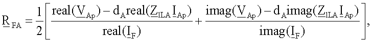


где „real” обозначает действительную часть заданной величины;
„imag” обозначает мнимую часть заданной величины;
V Ap - обозначает напряжение на контуре повреждения, вычисляемое в предположении, что повреждение произошло на участке LA;
V Tp - обозначает напряжение на контуре повреждения, вычисляемое в предположении, что повреждение произошло на участке LB или LC;
I Ap - обозначает контурный ток повреждения, вычисляемый в предположении, что повреждение произошло на участке LA;
I TBp - обозначает контурный ток повреждения, вычисляемый в предположении, что повреждение произошло на участке LB;
I TCp - обозначает контурный ток повреждения, вычисляемый в предположении, что повреждение произошло на участке LC линии;
I F - обозначает полный ток повреждения;
Z 1LA=R1LA+jω1L1LA - обозначает импеданс участка LA линии для положительной последовательной составляющей;
Z 1LB=R1LB+jω1L1LB - обозначает импеданс участка LB линии для положительной последовательной составляющей;
Z 1LC=R1LC+jω1L1LC - обозначает импеданс участка LC линии для положительной последовательной составляющей;
R1LA, R1LB, R1LC - сопротивление для положительной последовательной составляющей для участков LA, LB, LC линии соответственно;
L1LA, L1LB, L1LC - индуктивность для положительной последовательной составляющей для участков LA, LB, LC линии соответственно;
ω1 - угловая частота переменного тока для основной частоты;
dA - обозначает расстояние от начала линии до точки повреждения, dB - обозначает расстояние от конца линии до точки повреждения;
dC - обозначает расстояние от конца линии передачи с ответвлениями до точки повреждения.5. The method according to claim 1, characterized in that for three-terminal power lines, the resistance R FA , R FB , R FC at the fault location is determined from the following equations:
where "real" denotes the real part of a given value;
“Imag” means the imaginary part of a given quantity;
V Ap - indicates the voltage on the damage circuit, calculated on the assumption that the damage occurred on the LA;
V Tp - indicates the voltage on the fault loop, calculated on the assumption that the damage occurred on the LB or LC;
I Ap - denotes the fault loop current, calculated on the assumption that the fault occurred in LA;
I TBp - indicates the loop fault current, calculated on the assumption that the fault occurred in the LB section;
I TCp - indicates the loop fault current, calculated on the assumption that the fault occurred on the LC line section;
I F - indicates the total fault current;
Z 1LA = R 1LA + jω 1 L 1LA - indicates the impedance of the portion of the LA line for the positive serial component;
Z 1LB = R 1LB + jω 1 L 1LB - indicates the impedance of the portion of the LB line for the positive serial component;
Z 1LC = R 1LC + jω 1 L 1LC - indicates the impedance of the portion of the LC line for the positive serial component;
R 1LA , R 1LB , R 1LC - resistance for the positive serial component for sections of LA, LB, LC lines, respectively;
L 1LA , L 1LB , L 1LC - inductance for the positive serial component for sections of LA, LB, LC lines, respectively;
ω 1 is the angular frequency of the alternating current for the fundamental frequency;
d A - indicates the distance from the beginning of the line to the point of damage, d B - indicates the distance from the end of the line to the point of damage;
d C - indicates the distance from the end of the transmission line with branches to the point of damage.
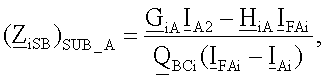
где нижний индекс i принимает значения i=2 для отрицательной последовательной составляющей, i=Δ1 для инкрементной положительной последовательной составляющей;
G iA - обозначает первый аналитический коэффициент для отрицательной последовательной составляющей, определяемой из анализа эквивалентной принципиальной схемы системы (показана на фиг.11) и/или для инкрементной положительной последовательной составляющей, аналитически определяемой из эквивалентной принципиальной схемы системы, (показана на фиг.12);
I Ai - обозначает отрицательную и/или инкрементную положительную последовательную составляющую тока, измеренного в начале линии;
H Ai - обозначает второй аналитический коэффициент для отрицательной последовательной составляющей, определяемой из анализа эквивалентной принципиальной схемы системы (показана на фиг.11) и/или для инкрементной положительной последовательной составляющей, аналитически определяемой из эквивалентной принципиальной схемы системы (показана на фиг.12);
I FAi - обозначает отрицательную последовательную составляющую полного тока повреждения, определяемую из анализа эквивалентной принципиальной схемы системы (показана на фиг.11) и/или инкрементную положительную последовательную составляющую полного тока повреждения, определяемую из эквивалентной принципиальной схемы системы (показана на фиг.12);
Q BCi - обозначает отношение отрицательной последовательной составляющей тока, измеренной на конце линии, и суммы отрицательных последовательных составляющих сигналов тока, измеренных на конце линии и на конце линии передачи с ответвлениями, и/или отношение инкрементной положительной последовательной составляющей тока, измеренной на конце линии, и суммы инкрементных положительных последовательных составляющих сигналов тока, измеренных на конце линии и на конце линии передачи с ответвлениями.6. The method according to claim 1, characterized in that for three-terminal power lines, the impedances of an equivalent source for a negative serial component ( Z 2SB ) SUB-A ) and for an incremental positive serial component ( Z Δ1SB ) SUB-A ) are calculated under the assumption that the damage occurred on the section of the LA line, according to the equation:
where the subscript i takes values i = 2 for the negative sequential component, i = Δ1 for the incremental positive sequential component;
G iA - denotes the first analytical coefficient for the negative sequential component determined from the analysis of the equivalent circuit diagram of the system (shown in Fig. 11) and / or for the incremental positive serial component analytically determined from the equivalent circuit diagram of the system (shown in Fig. 12) ;
I Ai - denotes the negative and / or incremental positive sequential component of the current measured at the beginning of the line;
H Ai - denotes the second analytical coefficient for the negative serial component determined from the analysis of the equivalent circuit diagram of the system (shown in Fig. 11) and / or for the incremental positive serial component analytically determined from the equivalent circuit diagram of the system (shown in Fig. 12);
I FAi - denotes the negative sequential component of the total fault current determined from the analysis of the equivalent circuit diagram of the system (shown in FIG. 11) and / or the incremental positive serial component of the total fault current determined from the equivalent circuit diagram of the system (shown in FIG. 12);
Q BCi - denotes the ratio of the negative serial component of the current measured at the end of the line and the sum of the negative serial components of the current signals measured at the end of the line and at the end of the transmission line with branches, and / or the ratio of the incremental positive serial component of the current measured at the end of the line, and the sum of the incremental positive sequential components of the current signals measured at the end of the line and at the end of the transmission line with branches.
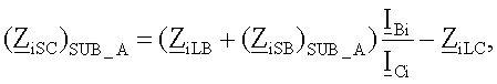
где нижний индекс i принимает значения i=2 для отрицательной последовательной составляющей, i=Δ1 для инкрементной положительной последовательной составляющей;
(Z iSB)SUB-A) - обозначает импеданс эквивалентных источников для отрицательной последовательной составляющей и/или для инкрементной положительной последовательной составляющей, вычисляемой в предположении, что повреждение произошло на участке LA линии;
Z iLB - обозначает импеданс участка LB линии для отрицательной последовательной составляющей и/или для инкрементной положительной последовательной составляющей, где Z Δ1LB=Z 1LB;
Z lLB - обозначает импеданс участка LB линии для положительной последовательной составляющей;
Z iLC - обозначает импеданс участка LC линии для отрицательной последовательной составляющей и/или импеданс участка LC линии для инкрементной положительной последовательной составляющей, где
Z 2LC=Z 1LC и Z Δ1LC=Z 1LC;
Z lLC - обозначает импеданс участка LC линии для положительной последовательной составляющей;
I Bi - обозначает отрицательную последовательную составляющую и/или инкрементную положительную последовательную составляющую тока, измеренную на конце линии;
I Ci - обозначает отрицательную последовательную составляющую и/или инкрементную положительную последовательную составляющую тока, измеренную на конце ответвления.7. The method according to claim 1, characterized in that for three-terminal power lines, the impedance ( Z 2SC ) SUB-A ) of the equivalent source for the negative serial component and ( Z ΔlSC ) SUB-A ) for the incremental positive serial component are calculated under the assumption that damage occurred on the LA line section, from the following equation:
where the subscript i takes values i = 2 for the negative sequential component, i = Δ1 for the incremental positive sequential component;
( Z iSB ) SUB-A ) denotes the impedance of equivalent sources for the negative sequential component and / or for the incremental positive sequential component, calculated under the assumption that the damage occurred on the portion of the LA line;
Z iLB - denotes the impedance of the portion of the LB line for the negative sequential component and / or for the incremental positive sequential component, where Z Δ1LB = Z 1LB ;
Z lLB - indicates the impedance of the portion of the LB line for the positive serial component;
Z iLC - indicates the impedance of the portion of the LC line for the negative serial component and / or the impedance of the portion of the LC line for the incremental positive serial component, where
Z 2LC = Z 1LC and Z Δ1LC = Z 1LC ;
Z lLC - indicates the impedance of the portion of the LC line for the positive serial component;
I Bi - denotes a negative sequential component and / or incremental positive sequential component of the current, measured at the end of the line;
I Ci - denotes the negative sequential component and / or the incremental positive sequential component of the current, measured at the end of the branch.

где нижний индекс i принимает значения i=2 для отрицательной последовательной составляющей, i=Δ1 для инкрементной положительной последовательной составляющей;
dB - обозначает расстояние от конца линии до точки повреждения;
Z iLB - обозначает импеданс участка LB линии для отрицательной последовательной составляющей и/или для положительной последовательной составляющей, где Z Δ1LB=Z 1LB;
Z Δ1LB - обозначает импеданс участка LB линии для положительной последовательной составляющей;
I Bi - обозначает отрицательную последовательную составляющую и/или инкрементную положительную последовательную составляющую тока, измеренную на конце линии;
where the subscript i takes values i = 2 for the negative sequential component, i = Δ1 for the incremental positive sequential component;
d B - indicates the distance from the end of the line to the point of damage;
Z iLB - denotes the impedance of the portion of the LB line for the negative serial component and / or for the positive serial component, where Z Δ1LB = Z 1LB ;
Z Δ1LB - indicates the impedance of the portion of the LB line for the positive serial component;
I Bi - denotes a negative sequential component and / or incremental positive sequential component of the current, measured at the end of the line;

где нижний индекс i принимает значения i=2 для отрицательной последовательной составляющей, i=Δ1 для инкрементной положительной последовательной составляющей;
V Ci - обозначает вычисленную отрицательную последовательную составляющую и/или инкрементную положительную последовательную составляющую напряжения на конце линии передачи с ответвлениями;
I Ci - обозначает отрицательную последовательную составляющую и/или инкрементную положительную последовательную составляющую тока, измеренную на конце ответвления.9. The method according to claim 1, characterized in that for three-terminal power lines the impedance of the equivalent source for the negative serial component ( Z 2SC ) SUB-B ) and for the incremental positive serial component ( Z Δ1SC ) SUB-B ) is calculated under the assumption that damage occurred on the LB line section, from the following equation:
where the subscript i takes values i = 2 for the negative sequential component, i = Δ1 for the incremental positive sequential component;
V Ci - denotes the calculated negative series component and / or incremental positive series component of the voltage at the end of the transmission line with branches;
I Ci - denotes the negative sequential component and / or the incremental positive sequential component of the current, measured at the end of the branch.
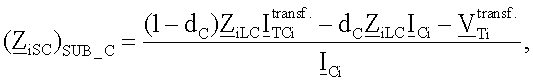
где нижний индекс i принимает значения i=2 для отрицательной последовательной составляющей, i=Δ1 для инкрементной положительной последовательной составляющей;
dc - обозначает расстояние от конца линии передачи с ответвлениями до точки повреждения;
Z iLC - обозначает импеданс участка LC линии для отрицательной последовательной составляющей и/или для инкрементной положительной последовательной составляющей, где Z 2LC=Z lLC и Z ΔlLC=Z lLC;
Z lLC - обозначает импеданс участка LC линии для положительной последовательной составляющей;
I Ci - обозначает отрицательную последовательную составляющую и/или инкрементную положительную последовательную составляющую тока, измеренную на конце ответвления;
where the subscript i takes values i = 2 for the negative sequential component, i = Δ1 for the incremental positive sequential component;
d c - indicates the distance from the end of the transmission line with branches to the point of damage;
Z iLC - indicates the impedance of the portion of the LC line for the negative serial component and / or for the incremental positive serial component, where Z 2LC = Z lLC and Z ΔlLC = Z lLC ;
Z lLC - indicates the impedance of the portion of the LC line for the positive serial component;
I Ci - denotes a negative sequential component and / or incremental positive sequential component of the current, measured at the end of the branch;

где нижний индекс i принимает значения i=2 для отрицательной последовательной составляющей, i=Δ1 для инкрементной положительной последовательной составляющей;
V Bi - обозначает отрицательную последовательную и/или инкрементную положительную последовательную составляющую напряжения на конце линии;
I Bi - обозначает отрицательную последовательную и/или инкрементную положительную последовательную составляющую тока, измеренного на конце линии.11. The method according to claim 1, characterized in that for three-terminal power lines the impedance of the equivalent source for the negative serial component ( Z 2SB ) SUB-C and for the incremental positive serial component ( Z ΔlSB ) SUB-C is calculated under the assumption that the damage has occurred on the LC line section, from the following equation:
where the subscript i takes values i = 2 for the negative sequential component, i = Δ1 for the incremental positive sequential component;
V Bi - denotes the negative sequential and / or incremental positive serial component of the voltage at the end of the line;
I Bi - denotes the negative sequential and / or incremental positive sequential component of the current measured at the end of the line.
где V lp - напряжение на контуре повреждения, вычисляемое в предположении, что повреждение произошло на участке L1 линии;
I lp - контурный ток повреждения, вычисляемый в предположении, что повреждение произошло на первом участке L1 линии;
V T(n-1)np - напряжение на контуре повреждения, вычисляемое в предположении, что повреждение произошло на участке L(2n-3) линии;
I T(n-1)np - контурный ток повреждения, вычисляемый в предположении, что повреждение произошло на участке L(2n-3) линии;
V Tkkp - напряжение на контуре повреждения, вычисляемое в предположении, что повреждение произошло в koй линии передачи с ответвлениями;
I Tkkp - контурный ток повреждения, вычисляемый в предположении, что повреждение произошло в koй линии передачи с ответвлениями;
V TkT(k+1)p - напряжение на контуре повреждения, вычисляемое в предположении, что повреждение произошло на участке линии между двумя точками ответвления;
I TkT(k+1)p - контурный ток повреждения, вычисляемый в предположении, что повреждение произошло на участке линии между двумя точками ответвления;
I F - полный ток повреждения;
Z lLl - импеданс участка L1 линии для положительной последовательной составляющей;
Z 0Ll - импеданс участка L1 линии для нулевой последовательной составляющей;
Z lL(2n-3) - импеданс участка L(2n-3) линии для положительной последовательной составляющей;
Z 0L(2n-3) - импеданс участка L(2n-3) линии для нулевой последовательной составляющей;
Z lL(2k-2) - импеданс участка L(2k-2) линии для положительной последовательной составляющей;
Z 0L(2k-2) - импеданс участка L(2k-2) линии для нулевой последовательной составляющей;
Z lL(2k-1) - импеданс участка L(2k-1) линии для положительной последовательной составляющей;
Z 0L(2k-1) - импеданс участка L(2k-1) линии для нулевой последовательной составляющей;
k - номер точки ответвления;
n - номер терминала линии.12. The method according to claim 1, characterized in that for multi-terminal power lines, the distance from the beginning of the line to the point of damage (d 1 ), from the end of the line to the point of damage (d ( 2n-3 )), from the end of the line to the point of damage ( d ( 2k-2 )), from the point of branching to the point of damage on a section of the line between two points of branching (d ( 2k-1 )) is determined from the following equations:
where V lp is the voltage on the damage circuit, calculated under the assumption that the damage occurred on the L1 line section;
I lp is the loop fault current calculated on the assumption that the fault occurred on the first section of the L1 line;
V T (n-1) np is the voltage on the damage circuit, calculated on the assumption that the damage occurred on the section L (2n-3) of the line;
I T (n-1) np is the fault loop current calculated on the assumption that the fault occurred on a portion of the L (2n-3) line;
V Tkkp is the voltage on the damage circuit, calculated on the assumption that the damage occurred on the k- th transmission line with branches;
I Tkkp - contour fault current, calculated under the assumption that the damage occurred in the k- th transmission line with branches;
V TkT (k + 1) p is the voltage on the damage circuit, calculated under the assumption that the damage occurred on a section of the line between two branch points;
I TkT (k + 1) p is the fault loop current calculated on the assumption that the fault occurred on a section of the line between two branch points;
I F is the total fault current;
Z lLl is the impedance of the line section L1 for the positive serial component;
Z 0Ll is the impedance of the line section L1 for the zero serial component;
Z lL (2n-3) is the impedance of the portion of the L (2n-3) line for the positive serial component;
Z 0L (2n-3) is the impedance of the portion of the L (2n-3) line for the zero serial component;
Z lL (2k-2) is the impedance of the portion of the L (2k-2) line for the positive serial component;
Z 0L (2k-2) is the impedance of the portion of the L (2k-2) line for the zero serial component;
Z lL (2k-1) is the impedance of the portion of the L (2k-1) line for the positive serial component;
Z 0L (2k-1) is the impedance of the portion L (2k-1) of the line for the zero sequential component;
k is the number of the branch point;
n is the terminal number of the line.

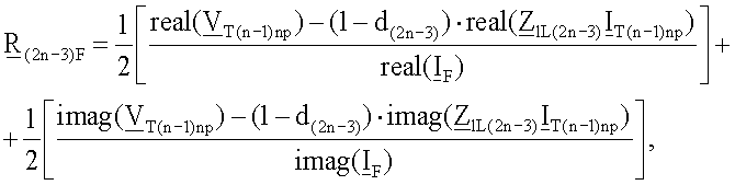


где (d1) - расстояние до повреждения от начала линии до точки повреждения;
(d(2n-3)) - расстояние до повреждения от конца линии до точки повреждения;
(d(2k-2))- расстояние до повреждения от конца линии передачи с ответвлениями до точки повреждения;
(d(2k-1))- расстояние до повреждения на участке линии между двумя точками ответвления;
V 1p - напряжение на контуре повреждения, вычисляемое в предположении, что повреждение произошло на первом участке L1 линии;
I 1p - контурный ток повреждения, вычисляемый в предположении, что повреждение произошло на первом участке L1 линии;
V T(n-1)np - напряжение на контуре повреждения, вычисляемое в предположении, что повреждение произошло на участке L(2n-3) линии;
I T(n-1)np - контурный ток повреждения, вычисляемый в предположении, что повреждение произошло на участке L(2n-3) линии;
V Tkkp - напряжение на контуре повреждения, вычисляемое в предположении, что повреждение произошло в koй линии передачи с ответвлениями;
I Tkkp - контурный ток повреждения, вычисляемый в предположении, что повреждение произошло в koй линии передачи с ответвлениями;
V TkT(k+1)p - напряжение на контуре повреждения, вычисляемое в предположении, что повреждение произошло на участке линии между двумя точками ответвления;
I TkT(k+1)p - контурный ток повреждения, вычисляемый в предположении, что повреждение произошло на участке линии между двумя точками ответвления;
I F - полный ток повреждения;
Z lLl - импеданс участка L1 линии для положительной последовательной составляющей;
Z 0Ll - импеданс участка L1 линии для нулевой последовательной составляющей;
Z lL(2n-3) - импеданс участка L(2n-3) линии для положительной последовательной составляющей;
Z 0L(2n-3) - импеданс участка L(2n-3) линии для нулевой последовательной составляющей;
Z lL(2k-2) - импеданс участка L(2k-2) линии для положительной последовательной составляющей;
Z 0L(2k-2) - импеданс участка L(2k-2) линии для нулевой последовательной составляющей;
Z lL(2k-1) - импеданс участка L(2k-1) линии для положительной последовательной составляющей;
Z 0L(2k-1) - импеданс участка L(2k-1) линии для нулевой последовательной составляющей;
k - номер точки ответвления;
n - номер терминала линии.13. The method according to claim 1, characterized in that for multi-terminal power lines resistance ( R 1F ), ( R (2n-3) F ), ( R (2k-2) F ), ( R (2k-1) F ) in the place of damage is determined from the following equations:
where (d 1 ) is the distance to the damage from the beginning of the line to the point of damage;
(d ( 2n-3 )) is the distance to the damage from the end of the line to the point of damage;
(d ( 2k-2 )) is the distance to the damage from the end of the transmission line with branches to the point of damage;
(d ( 2k-1 )) is the distance to damage on the line section between two branch points;
V 1p is the voltage on the damage circuit, calculated on the assumption that the damage occurred on the first section of the L1 line;
I 1p is the fault loop current calculated on the assumption that the fault occurred on the first section of the L1 line;
V T (n-1) np is the voltage on the damage circuit, calculated on the assumption that the damage occurred on the section L (2n-3) of the line;
I T (n-1) np is the fault loop current calculated on the assumption that the fault occurred on a portion of the L (2n-3) line;
V Tkkp is the voltage on the damage circuit, calculated on the assumption that the damage occurred on the k- th transmission line with branches;
I Tkkp - contour fault current, calculated under the assumption that the damage occurred in the k- th transmission line with branches;
V TkT (k + 1) p is the voltage on the damage circuit, calculated under the assumption that the damage occurred on a section of the line between two branch points;
I TkT (k + 1) p is the fault loop current calculated on the assumption that the fault occurred on a section of the line between two branch points;
I F is the total fault current;
Z lLl is the impedance of the line section L1 for the positive serial component;
Z 0Ll is the impedance of the line section L1 for the zero serial component;
Z lL (2n-3) is the impedance of the portion of the L (2n-3) line for the positive serial component;
Z 0L (2n-3) is the impedance of the portion of the L (2n-3) line for the zero serial component;
Z lL (2k-2) is the impedance of the portion of the L (2k-2) line for the positive serial component;
Z 0L (2k-2) is the impedance of the portion of the L (2k-2) line for the zero serial component;
Z lL (2k-1) is the impedance of the portion of the L (2k-1) line for the positive serial component;
Z 0L (2k-1) is the impedance of the portion L (2k-1) of the line for the zero sequential component;
k is the number of the branch point;
n is the terminal number of the line.
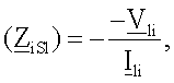
где i=2 для отрицательной последовательной составляющей, i=Δ1 для инкрементной положительной последовательной составляющей;
V li - напряжение, измеренное на станции 1 для отдельных симметричных составляющих (первый нижний индекс), а второй нижний индекс для отрицательной последовательной составляющей будет равен 2 и для инкрементной положительной последовательной составляющей будет равен Δ1;
I li - ток, измеренный на станции 1 для отдельных симметричных составляющих (первый нижний индекс), а второй нижний индекс для отрицательной последовательной составляющей будет равен 2 и для инкрементной положительной последовательной составляющей будет равен Δ1.14. The method according to claim 1, characterized in that for multi-terminal power lines, the impedance equivalent to the negative serial component ( Z 2Sl ) or for the incremental positive serial component ( Z ΔlSl ) is calculated under the assumption that the damage is located on the line section between the beginning of the line and the first branch point according to the following equation:
where i = 2 for the negative sequential component, i = Δ1 for the incremental positive sequential component;
V li is the voltage measured at station 1 for individual symmetrical components (the first subscript), and the second subscript for the negative sequential component will be 2 and for the incremental positive sequential component will be Δ1;
I li is the current measured at station 1 for individual symmetrical components (the first subscript), and the second subscript for the negative sequential component will be 2 and for the incremental positive sequential component will be Δ1.
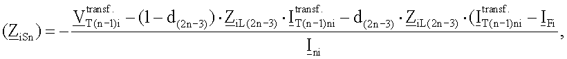
где i=2 для отрицательной последовательной составляющей, Δ1 для инкрементной положительной последовательной составляющей;
d(2n-3) - расстояние до повреждения от конца линии до точки повреждения;
Z iL(2n-3) - импеданс участка L(2n-3) линии для отрицательной последовательной составляющей i=2 или для инкрементной положительной последовательной составляющей i=Δ1;
I Fi - полный ток повреждения для отрицательной последовательной составляющей i=2 или для инкрементной положительной последовательной составляющей i=Δ1;
I ni - ток, измеренный на последней станции n для отдельных симметричных составляющих (первый нижний индекс), а второй нижний индекс для отрицательной последовательной составляющей будет = 2 и для инкрементной положительной последовательной составляющей будет i=Δ1.15. The method according to claim 1, characterized in that for multi-terminal power lines, the impedance (( Z 2S (n) )) of the equivalent source for the negative serial component and (( Z Δ1S (n) )) for the incremental positive serial component is determined under the assumption that the damage is located on the line segment between the end of the line and the last branch point, from the following equation:
where i = 2 for the negative sequential component, Δ1 for the incremental positive sequential component;
d (2n-3) is the distance to the damage from the end of the line to the point of damage;
Z iL (2n-3) is the impedance of the portion of the L (2n-3) line for the negative sequential component i = 2 or for the incremental positive sequential component i = Δ1;
I Fi is the total fault current for the negative serial component i = 2 or for the incremental positive serial component i = Δ1;
I ni is the current measured at the last station n for individual symmetrical components (the first subscript), and the second subscript for the negative sequential component will be = 2 and for the incremental positive sequential component will be i = Δ1.

где
d(2k-2) - расстояние до повреждения от конца линии передачи с ответвлениями до точки повреждения Tk;
Z iL(2k-2) - импеданс участка L(2k-2) линии для отрицательной последовательной составляющей i=2 или для инкрементной положительной последовательной составляющей i=Δl;
I Fi - полный ток повреждения для отрицательной последовательной составляющей i=2 или для инкрементной положительной последовательной составляющей i=Δ1;
I ki - ток, измеренный на станции k для отдельных симметричных составляющих (первый нижний индекс), а второй нижний индекс для отрицательной последовательной составляющей будет = 2 и для инкрементной положительной последовательной составляющей будет i=Δ1.16. The method according to claim 1, characterized in that for multi-terminal power lines, the impedance of the equivalent source for the negative serial component (( Z 2Sk )) and for the incremental positive serial component (( Z Δ1Sk )) is determined under the assumption that the damage is located on the line branch gears from the following equation:
Where
d (2k-2) - distance to damage from the end of the transmission line with branches to the damage point Tk;
Z iL (2k-2) is the impedance of the line segment L (2k-2) for the negative sequential component i = 2 or for the incremental positive sequential component i = Δl;
I Fi is the total fault current for the negative serial component i = 2 or for the incremental positive serial component i = Δ1;
I ki is the current measured at station k for individual symmetrical components (the first subscript), and the second subscript for the negative sequential component will be = 2 and for the incremental positive sequential component will be i = Δ1.
где
d(2k-1) - расстояние до повреждения на участке линии между двумя точками ответвления;
Z iL(2k-1) - импеданс участка L(2k-l) линии для отрицательной последовательной составляющей i=2 или для инкрементной положительной последовательной составляющей i=Δ1;
I Fi - полный ток повреждения для отрицательной последовательной составляющей i=2 или для инкрементной положительной последовательной составляющей i=Δ1;
I ki - ток, измеренный на станции k для отдельных симметричных составляющих (первый нижний индекс), а второй нижний индекс для отрицательной последовательной составляющей будет равен 2 и для инкрементной положительной последовательной составляющей будет i=Δ1;
I (k+1)i - ток, измеренный на станции k+1 для отдельных симметричных составляющих (первый нижний индекс), а второй нижний индекс для отрицательной последовательной составляющей будет равен 2 и для инкрементной положительной последовательной составляющей будет i=Δ1. 17. The method according to claim 1, characterized in that for multi-terminal power lines, the impedance of an equivalent source for the negative serial component (( Z 2Sk )) and (( Z 2S (k + 1) )), as well as for the incremental positive serial component ( ( Z Δ1Sk )) and (( Z Δ1Sk (k + 1) )) are determined under the assumption that the damage is located on the line segment between two consecutive branch points from the following equations:
Where
d (2k-1) is the distance to damage on the line section between two branch points;
Z iL (2k-1) is the impedance of the line segment L (2k-l) for the negative sequential component i = 2 or for the incremental positive sequential component i = Δ1;
I Fi is the total fault current for the negative serial component i = 2 or for the incremental positive serial component i = Δ1;
I ki is the current measured at station k for individual symmetrical components (the first subscript), and the second subscript for the negative sequential component will be 2 and for the incremental positive sequential component will be i = Δ1;
I (k + 1) i is the current measured at station k + 1 for individual symmetrical components (the first subscript), and the second subscript for the negative sequential component will be 2 and for the incremental positive sequential component will be i = Δ1.
Applications Claiming Priority (4)
| Application Number | Priority Date | Filing Date | Title |
|---|---|---|---|
| PLP377064 | 2005-09-14 | ||
| PL377064A PL206226B1 (en) | 2005-09-14 | 2005-09-14 | Method for the location of short-circuits in single branch power transmission lines |
| PLP380012 | 2006-06-23 | ||
| PL380012A PL207942B1 (en) | 2006-06-23 | 2006-06-23 | The manner of location of short-circuits in power engineering lines with numerous branches |
Publications (2)
| Publication Number | Publication Date |
|---|---|
| RU2008114387A RU2008114387A (en) | 2009-10-20 |
| RU2397503C2 true RU2397503C2 (en) | 2010-08-20 |
Family
ID=37685253
Family Applications (1)
| Application Number | Title | Priority Date | Filing Date |
|---|---|---|---|
| RU2008114387/28A RU2397503C2 (en) | 2005-09-14 | 2006-09-05 | Method of determining point of fault in power line |
Country Status (5)
| Country | Link |
|---|---|
| US (1) | US8131485B2 (en) |
| EP (1) | EP1924863B1 (en) |
| ES (1) | ES2456290T3 (en) |
| RU (1) | RU2397503C2 (en) |
| WO (1) | WO2007032697A1 (en) |
Cited By (5)
| Publication number | Priority date | Publication date | Assignee | Title |
|---|---|---|---|---|
| RU2492565C1 (en) * | 2012-07-17 | 2013-09-10 | Общество с ограниченной ответственностью "Исследовательский центр "Бреслер" | Method of determining point of fault of electric power transmission line with two-way observation |
| RU2586438C1 (en) * | 2015-04-29 | 2016-06-10 | Степан Георгиевич Тигунцев | Method of determining location of short circuit at long power line of voltage 220 kv and higher |
| RU2593405C1 (en) * | 2015-07-01 | 2016-08-10 | Степан Георгиевич Тигунцев | Method of determining point of wire breakage on overhead transmission line |
| RU2593409C1 (en) * | 2015-07-13 | 2016-08-10 | Степан Георгиевич Тигунцев | Method of determining location of short circuit at long power line with spur line |
| RU2633433C2 (en) * | 2012-12-06 | 2017-10-12 | Шнейдер Электрик Эндюстри Сас | Directional detection of fault in network, in particular, in system with grounded compensated or insulated neutral |
Families Citing this family (54)
| Publication number | Priority date | Publication date | Assignee | Title |
|---|---|---|---|---|
| FR2922028B1 (en) * | 2007-10-05 | 2011-04-29 | Schneider Electric Ind Sas | LOCATING A DEFECT IN A MEDIUM VOLTAGE PUBLIC DISTRIBUTION NETWORK |
| EP2232280A1 (en) * | 2008-01-24 | 2010-09-29 | Siemens Aktiengesellschaft | Method and fault locator for determining a fault location value |
| EP2113778B1 (en) | 2008-04-29 | 2017-12-06 | ABB Schweiz AG | System and method for determining location of phase-to-phase fault or three-phase fault |
| RU2480777C2 (en) * | 2008-07-18 | 2013-04-27 | Абб Текнолоджи Аг | Method and device to detect locations of transmission lines damage with longitudinal compensation |
| US8525522B2 (en) | 2010-04-21 | 2013-09-03 | Schweitzer Engineering Laboratories Inc | Fault location in electric power delivery systems |
| US8558551B2 (en) | 2010-04-21 | 2013-10-15 | Schweitzer Engineering Laboratories Inc | Fault location in electric power delivery systems |
| US8942954B2 (en) * | 2010-09-16 | 2015-01-27 | Schweitzer Engineering Laboratories, Inc. | Fault location in a non-homogeneous electric power line |
| US8922652B2 (en) | 2011-08-29 | 2014-12-30 | General Electric Company | Systems and methods for locating faults in a power system |
| US8791704B2 (en) | 2011-10-11 | 2014-07-29 | Schweitzer Engineering Laboratories Inc. | Fault-type identification for electric power delivery systems |
| CN103368166B (en) * | 2012-03-29 | 2016-04-06 | 徐州润泽电气有限公司 | A kind of zero sequence total current power direction realizes the method for coalmine high-voltage power network selective earth leakage protection |
| CN102967801B (en) * | 2012-12-13 | 2015-01-07 | 山东理工大学 | T-line three-end traveling wave fault location method |
| US10401417B2 (en) * | 2013-02-13 | 2019-09-03 | General Electric Technology Gmbh | Electrical fault location determination in a distribution system based on phasor information |
| CN103197204B (en) * | 2013-04-07 | 2015-04-29 | 山东电力集团公司德州供电公司 | Mixed type method of multi-terminal circuit fault location |
| RU2558265C1 (en) * | 2014-04-29 | 2015-07-27 | Федеральное государственное бюджетное образовательное учреждение высшего профессионального образования "Казанский государственный энергетический университет" (ФГБОУ ВПО "КГЭУ") | Determination of distance to points of double earth connection at electric power transmission lines in networks with low earth currents |
| RU2557375C1 (en) * | 2014-04-29 | 2015-07-20 | Федеральное государственное бюджетное образовательное учреждение высшего профессионального образования "Казанский государственный энергетический университет" (ФГБОУ ВПО "КГЭУ") | Determination of distance to points of earth connection at two electric power transmission lines in networks with low earth currents |
| RU2558266C1 (en) * | 2014-04-29 | 2015-07-27 | Федеральное государственное бюджетное образовательное учреждение высшего профессионального образования "Казанский государственный энергетический университет" (ФГБОУ ВПО "КГЭУ") | Method of finding of distance to places of earth faults on two power lines in networks with low earth fault currents |
| DE102014217972A1 (en) * | 2014-09-09 | 2016-03-10 | Siemens Aktiengesellschaft | Method and arrangement for determining a fault location in the event of a short circuit along a power supply line with a plurality of conductors |
| RU2586453C1 (en) * | 2015-04-22 | 2016-06-10 | федеральное государственное бюджетное образовательное учреждение высшего образования "Иркутский национальный исследовательский технический университет" (ФГБОУ ВО "ИРНИТУ") | Method of determining point of short-circuit on overhead power transmission line at non-synchronised measurements on both ends thereof |
| CN105044550A (en) * | 2015-04-28 | 2015-11-11 | 国家电网公司 | Distribution network line fault positioning method based on fault current discharge path |
| EP3203248B1 (en) * | 2016-02-02 | 2023-11-22 | General Electric Technology GmbH | Method of locating a fault in a power transmission scheme |
| US10197614B2 (en) * | 2016-05-02 | 2019-02-05 | Schweitzer Engineering Laboratories, Inc. | Fault location during pole-open condition |
| RU2637378C1 (en) * | 2016-06-28 | 2017-12-04 | Галина Андреевна Филатова | Method of remote determination of single phase-to-ground-fault location |
| KR101737072B1 (en) * | 2016-07-13 | 2017-05-18 | 선광엘티아이(주) | Resistance and current observation system of the ground line |
| US10223906B2 (en) | 2017-01-23 | 2019-03-05 | Florida Power & Light Company | Open neutral detection |
| EP3662553A1 (en) * | 2017-08-04 | 2020-06-10 | ABB Power Grids Switzerland AG | Method and device for fault section identification in multi-terminal mixed lines |
| US11054456B2 (en) * | 2017-09-18 | 2021-07-06 | Sensus Spectrum Llc | Systems and method for determining load balance on a three-phase power distribution system |
| US11360137B2 (en) * | 2017-12-29 | 2022-06-14 | Hitachi Energy Switzerland Ag | Parameter free identification of fault location in multi-terminal power transmission lines |
| WO2019186490A1 (en) | 2018-03-31 | 2019-10-03 | Abb Schweiz Ag | Method and device for protection in a multi-terminal power transmission system |
| WO2019229638A1 (en) * | 2018-05-31 | 2019-12-05 | Abb Schweiz Ag | Fault location for parallel transmission lines with zero sequence currents estimated from faulted line measurements |
| US10859639B2 (en) | 2018-10-02 | 2020-12-08 | Schweitzer Engineering Laboratories, Inc. | Fault-type identification in an electric power delivery system using composite signals |
| CN109327027B (en) * | 2018-11-21 | 2022-07-22 | 广西电网有限责任公司电力科学研究院 | A fault checking method for crossover line based on PSD-BPA |
| EP3723224B1 (en) | 2019-04-08 | 2023-08-23 | Hitachi Energy Switzerland AG | Time domain distance protection based on polarity comparison for power transmission lines |
| CN112526281B (en) * | 2019-09-19 | 2023-04-14 | 国电南瑞科技股份有限公司 | A double-terminal distance measurement method for T-connection line faults |
| CN110726904B (en) * | 2019-09-27 | 2022-11-22 | 广西电网有限责任公司电力科学研究院 | A Method of Accurately Locating Fault Points Based on Distributed T-connection Transmission Circuit |
| CN110764019B (en) * | 2019-10-30 | 2021-07-30 | 国网湖北省电力有限公司电力科学研究院 | A method for determining and locating the temporary grounding quantity of a line based on double-ended measurement |
| RU2726042C1 (en) * | 2019-12-09 | 2020-07-08 | Федеральное государственное бюджетное учреждение науки Федеральный исследовательский центр "Кольский научный центр Российской академии наук" (ФИЦ КНЦ РАН) | Method of determining value of stationary resistance of earthing arrangement of supports of overhead power transmission lines without disconnection of overhead ground wire and device for its implementation |
| CN111781468B (en) * | 2020-07-15 | 2022-11-22 | 国网宁夏电力有限公司营销服务中心(国网宁夏电力有限公司计量中心) | Asynchronous fault distance measurement method and system for T-shaped high-voltage transmission line |
| EP3993204B1 (en) * | 2020-10-28 | 2023-09-27 | Katholieke Universiteit Leuven | Determining a fault location on a powerline |
| RU2750421C1 (en) * | 2020-12-21 | 2021-06-28 | федеральное государственное бюджетное образовательное учреждение высшего образования "Нижегородский государственный технический университет им. Р.Е. Алексеева" (НГТУ) | Method for determining distance to places of double earth faults on power lines in networks with low earth fault currents |
| US11735908B2 (en) | 2021-02-15 | 2023-08-22 | Schweitzer Engineering Laboratories, Inc. | Dependable open-phase detection in electric power delivery systems with inverter-based resources |
| CN114113875B (en) * | 2021-02-19 | 2024-10-25 | 李冰鑫 | A method for locating faults in power distribution lines |
| CN113848416A (en) * | 2021-04-19 | 2021-12-28 | 西安成林电力科技有限公司 | A method and device for accurately locating faults in railway power supply lines |
| CN114689988B (en) * | 2021-12-23 | 2024-11-15 | 天津大学 | A method for accurately locating faults in a petal-shaped distribution network containing inverter-type distributed power sources |
| US11650241B1 (en) | 2022-06-28 | 2023-05-16 | Schweitzer Engineering Laboratories, Inc. | Incremental quantities-based fault locating technique and system |
| CN115542071B (en) * | 2022-08-23 | 2024-08-27 | 国网吉林省电力有限公司白城供电公司 | Power distribution network fault positioning method for signal-free area |
| CN115954927A (en) * | 2022-09-23 | 2023-04-11 | 中国华能集团清洁能源技术研究院有限公司 | Method and system for determining transient synchronous stability coefficient of phase-locked synchronous grid-connected converter |
| CN115954928A (en) * | 2022-09-23 | 2023-04-11 | 盛东如东海上风力发电有限责任公司 | Stability analysis method and system for phase-locked grid-connected converter |
| US12385962B2 (en) | 2022-10-04 | 2025-08-12 | Schweitzer Engineering Laboratories, Inc. | Fault location estimation using incremental quantities |
| US12362556B2 (en) | 2023-03-07 | 2025-07-15 | Schweitzer Engineering Laboratories, Inc. | Single-ended broken conductor detection logic using incremental quantities |
| US12283733B2 (en) * | 2023-04-13 | 2025-04-22 | Radio Wires Inc. | Multi-tap transmission line system and methods thereof |
| CN117554753B (en) * | 2024-01-09 | 2024-04-12 | 山东大学 | A single-phase ground fault distance measurement method and terminal based on zero-sequence voltage and current |
| CN118884125B (en) * | 2024-08-07 | 2025-03-25 | 武汉华电顺承科技有限公司 | A method and system for determining phase difference of transmission line fault based on analog quantity characteristics |
| US12578374B2 (en) | 2024-08-28 | 2026-03-17 | Schweitzer Engineering Laboratories, Inc. | Multi-ended impedance-based fault locating for untransposed transmission lines |
| CN118858845B (en) * | 2024-09-26 | 2024-12-06 | 国网山东省电力公司莱西市供电公司 | Double-end positioning method, medium and equipment for hybrid transmission line faults |
Citations (3)
| Publication number | Priority date | Publication date | Assignee | Title |
|---|---|---|---|---|
| EP0464662A1 (en) * | 1990-06-29 | 1992-01-08 | Asea Brown Boveri Ab | Method and means for fault location in a multi-terminal network |
| US5485394A (en) * | 1990-05-31 | 1996-01-16 | Nissin Electric Company, Limited | Fault location method for a parallel two-circuit transmission line with n terminals |
| RU2248583C2 (en) * | 2002-11-04 | 2005-03-20 | ООО "Научно-производственный центр "Электробезопасность" | Method for location of single-phase ground fault in branched aerial power line with insulated neutral conductor |
Family Cites Families (1)
| Publication number | Priority date | Publication date | Assignee | Title |
|---|---|---|---|---|
| US4766549A (en) * | 1984-11-30 | 1988-08-23 | Electric Power Research Institute, Inc. | Single-ended transmission line fault locator |
-
2006
- 2006-09-05 US US11/991,130 patent/US8131485B2/en not_active Expired - Fee Related
- 2006-09-05 RU RU2008114387/28A patent/RU2397503C2/en not_active IP Right Cessation
- 2006-09-05 ES ES06784043.9T patent/ES2456290T3/en active Active
- 2006-09-05 EP EP06784043.9A patent/EP1924863B1/en not_active Not-in-force
- 2006-09-05 WO PCT/PL2006/000061 patent/WO2007032697A1/en not_active Ceased
Patent Citations (3)
| Publication number | Priority date | Publication date | Assignee | Title |
|---|---|---|---|---|
| US5485394A (en) * | 1990-05-31 | 1996-01-16 | Nissin Electric Company, Limited | Fault location method for a parallel two-circuit transmission line with n terminals |
| EP0464662A1 (en) * | 1990-06-29 | 1992-01-08 | Asea Brown Boveri Ab | Method and means for fault location in a multi-terminal network |
| RU2248583C2 (en) * | 2002-11-04 | 2005-03-20 | ООО "Научно-производственный центр "Электробезопасность" | Method for location of single-phase ground fault in branched aerial power line with insulated neutral conductor |
Cited By (5)
| Publication number | Priority date | Publication date | Assignee | Title |
|---|---|---|---|---|
| RU2492565C1 (en) * | 2012-07-17 | 2013-09-10 | Общество с ограниченной ответственностью "Исследовательский центр "Бреслер" | Method of determining point of fault of electric power transmission line with two-way observation |
| RU2633433C2 (en) * | 2012-12-06 | 2017-10-12 | Шнейдер Электрик Эндюстри Сас | Directional detection of fault in network, in particular, in system with grounded compensated or insulated neutral |
| RU2586438C1 (en) * | 2015-04-29 | 2016-06-10 | Степан Георгиевич Тигунцев | Method of determining location of short circuit at long power line of voltage 220 kv and higher |
| RU2593405C1 (en) * | 2015-07-01 | 2016-08-10 | Степан Георгиевич Тигунцев | Method of determining point of wire breakage on overhead transmission line |
| RU2593409C1 (en) * | 2015-07-13 | 2016-08-10 | Степан Георгиевич Тигунцев | Method of determining location of short circuit at long power line with spur line |
Also Published As
| Publication number | Publication date |
|---|---|
| RU2008114387A (en) | 2009-10-20 |
| ES2456290T3 (en) | 2014-04-21 |
| WO2007032697A1 (en) | 2007-03-22 |
| US8131485B2 (en) | 2012-03-06 |
| US20090150099A1 (en) | 2009-06-11 |
| EP1924863B1 (en) | 2014-01-15 |
| EP1924863A1 (en) | 2008-05-28 |
Similar Documents
| Publication | Publication Date | Title |
|---|---|---|
| RU2397503C2 (en) | Method of determining point of fault in power line | |
| CN101828119B (en) | Fault Location Method on Series Compensated Transmission Line Using Asynchronous Measurements at Both Ends | |
| EP2017632B1 (en) | Method for fault location in uncompensated power lines with two-end unsynchronized measurement | |
| EP2313791B1 (en) | Method and device for fault location of series-compensated transmission line | |
| US8462004B2 (en) | Method and arrangement for generating an error signal | |
| EP2000811B1 (en) | Method for determining location of phase-to-earth fault | |
| EP3564687B1 (en) | Determination of power transmission line parameters using asynchronous measurements | |
| EP1992954B1 (en) | Method for determining location of phase-to-earth fault | |
| US7298149B2 (en) | Fault location using measurements of current and voltage from one end of a line | |
| EP1342095B1 (en) | Fault location method and device | |
| EP1739441A1 (en) | Method and system for determining location of phase-to-earth fault | |
| CN101263394A (en) | Method for fault localization in power lines | |
| Sachdev et al. | Determining locations of faults in distribution systems | |
| Daisy et al. | Single phase fault location in power distribution network using combination of impedance based method and voltage sage matching algorithm | |
| EP3141918A1 (en) | Improvements in or relating to determining a fault location in a power transmission medium | |
| RU2801438C1 (en) | Method for determining location of a short circuit on an overhead power line with unsynchronized measurements from its two ends | |
| Gopalakrishnan et al. | Extension to Fault Location Algorithm Based on Synchronized Sampling | |
| HK1149854A (en) | Method and arrangement for generating an error signal |
Legal Events
| Date | Code | Title | Description |
|---|---|---|---|
| MM4A | The patent is invalid due to non-payment of fees |
Effective date: 20150906 |