RU2586453C1 - Method of determining point of short-circuit on overhead power transmission line at non-synchronised measurements on both ends thereof - Google Patents
Method of determining point of short-circuit on overhead power transmission line at non-synchronised measurements on both ends thereof Download PDFInfo
- Publication number
- RU2586453C1 RU2586453C1 RU2015115191/28A RU2015115191A RU2586453C1 RU 2586453 C1 RU2586453 C1 RU 2586453C1 RU 2015115191/28 A RU2015115191/28 A RU 2015115191/28A RU 2015115191 A RU2015115191 A RU 2015115191A RU 2586453 C1 RU2586453 C1 RU 2586453C1
- Authority
- RU
- Russia
- Prior art keywords
- line
- short circuit
- currents
- phase
- jωl
- Prior art date
Links
Images

Landscapes
- Locating Faults (AREA)
Abstract
Description
Предлагаемое изобретение относится к электроэнергетике и может быть использовано для определения места короткого замыкания на линиях электропередачи при несинхронизированных замерах с двух ее концов.The present invention relates to the electric power industry and can be used to determine the location of a short circuit on power lines with unsynchronized measurements from its two ends.
Изобретение относится к приоритетному направлению развития науки и технологий «Технологии создания энергосберегающих систем транспортировки, распределения и потребления тепла и электроэнергии» [Алфавитно-предметный указатель к Международной патентной классификации по приоритетным направлениям развития науки и технологий / Ю.Г. Смирнов, Е.В. Скиданова, С.А. Краснов. - М.: ПАТЕНТ, 2008. - с. 97], так как решает проблему уменьшения времени задержек при транспортировке электроэнергии потребителям в случае повреждения электрических сетей.The invention relates to a priority area of development of science and technology "Technologies for creating energy-saving systems for transportation, distribution and consumption of heat and electricity" [Alphabetical index to the International Patent Classification in priority areas of science and technology / Yu.G. Smirnov, E.V. Skidanova, S.A. Krasnov. - M.: PATENT, 2008 .-- p. 97], since it solves the problem of reducing the time delays in transporting electricity to consumers in the event of damage to the electrical networks.
Известен способ определения места повреждения на воздушных линиях электропередачи [Заявка RU №2009137563/28, G01R 31/08 (2006.01), дата публикации 20.04.2011], в котором измеряют с двух концов линии фазные напряжения и токи, преобразуют их в расчетные комплексные значения по предложенным выражениям, и, используя мнимые части расчетных величин, находят расчетным путем относительные и физические расстояния места повреждения от концов линии. В этом способе не используют эквивалентные параметры питающих систем, устранено влияние переходного сопротивления.A known method of determining the location of damage on overhead power lines [Application RU No. 2009137563/28, G01R 31/08 (2006.01), publication date 04/20/2011], in which phase voltages and currents are measured from both ends of the line, and converted to calculated complex values according to the proposed expressions, and using the imaginary parts of the calculated values, the relative and physical distances of the damage site from the ends of the line are calculated by calculation. In this method, the equivalent parameters of the supply systems are not used, the influence of the transition resistance is eliminated.
Признаками аналога, совпадающими с существенными признаками заявляемого способа, являются: измерение с двух концов линии (′ - один конец линии, ′′ - второй конец линии) не синхронизированных по углам фазных токов ![]()
![]()
![]()
![]()
![]()
![]()
![]()
![]()
Недостатком указанного способа является необходимость использования только мнимых составляющих расчетных величин.The disadvantage of this method is the need to use only imaginary components of the calculated values.
Указанный недостаток может приводить к погрешности в определении места повреждения из-за недостаточного объема учитываемых параметров.The indicated drawback may lead to an error in determining the location of damage due to insufficient volume of parameters taken into account.
Известен способ определения места короткого замыкания на воздушной линии электропередачи по замерам мгновенных значений токов и напряжений с одного конца линии [учебное пособие «Методы и приборы определения места короткого замыкания на линии», Ивановский ГЭУ, 1998].A known method of determining the location of a short circuit on an overhead power line by measuring the instantaneous values of currents and voltages from one end of the line [study guide "Methods and instruments for determining the location of a short circuit on the line", Ivanovo State University of Economics, 1998].
В данном способе измеряют на одном конце линии мгновенные значения фазного тока, тока нулевой последовательности, фазного напряжения, выбирают момент, когда ток в месте короткого замыкания равен нулю, что предполагает равенство нулю падения напряжения на переходном сопротивлении, и находят расстояние до места короткого замыкания по соотношению мгновенного значения напряжения на данном конце линии и удельного падения напряжения на одном километре линии.In this method, instantaneous values of the phase current, zero sequence current, phase voltage are measured at one end of the line, the moment is selected when the current at the point of the short circuit is zero, which assumes that the voltage drop at the transition resistance is equal to zero, and the distance to the place of the short circuit is found by the ratio of the instantaneous voltage at this end of the line and the specific voltage drop per kilometer of the line.
Аналогично определяют расстояние до места короткого замыкания по замерам с другого конца линии.Similarly, determine the distance to the short circuit by measuring from the other end of the line.
Признаками аналога, совпадающими с существенными признаками заявляемого способа, являются: измерение с двух концов линии не синхронизированных по времени фазных токов ![]()
![]()
![]()
![]()
![]()
![]()
![]()
![]()
Недостатком аналога являются: неучет угла сдвига в момент короткого замыкания между векторными диаграммами по концам линии, необходимость измерения дополнительно к фазному току тока нулевой последовательности. Кроме того, способ реализован только в величинах интегральных значений, а в величинах мгновенных значений описан только аналитически. Потому как далее производят замену мгновенного значения напряжения на данном конце линии и удельного падения напряжения на одном километре линии в момент перехода тока нулевой последовательности i0 через нулевое мгновенное значение на расчет проекции на мнимую ось, перпендикулярную вектору тока нулевой последовательности I0, интегральных величин ![]()
![]()
![]()
![]()
Указанный недостаток может приводить к погрешности в определении места повреждения из-за недостаточного объема учитываемых параметров.The indicated drawback may lead to an error in determining the location of damage due to insufficient volume of parameters taken into account.
Известен способ определения места повреждения на воздушных линиях электропередачи [Технология векторной регистрации параметров и ее применение для управления режимами ЕЭС России, Электро, №2, 2011, с. 2-5], в котором необходимость использования только мнимых составляющих расчетных величин устраняется. В этом способе предварительно измеряют угол между токами по концам линии. Что выполняют путем использования цифровых каналов связи между концами линии или путем использования спутниковой синхронизации времени. При использовании цифровых каналов связи углы определяют путем выполнения выборок синхронизированных по времени или путем постоянного вычисления времени прохождения сигнала между полукомплектами дифференциальной защиты линии. При использовании спутниковой синхронизации времени импульсы синхронизации времени получают от приемников сигнала ГЛОНАСС (GPS). Далее измеряют с двух концов линии фазные напряжения и токи, преобразуют их в расчетные комплексные значения по предложенным выражениям и, используя полные части расчетных величин, находят расчетным путем относительные и физические расстояния места повреждения от концов линии. В этом способе не используют эквивалентные параметры питающих систем, устранено влияние переходного сопротивления.A known method of determining the location of damage on overhead power lines [Technology for vector recording parameters and its application to control the modes of the UES of Russia, Electro, No. 2, 2011, p. 2-5], in which the need to use only imaginary components of the calculated values is eliminated. In this method, the angle between the currents at the ends of the line is pre-measured. What is done by using digital communication channels between the ends of the line or by using satellite time synchronization. When using digital communication channels, the angles are determined by sampling time-synchronized or by constantly calculating the signal travel time between half-sets of differential protection of the line. When using satellite time synchronization, time synchronization pulses are received from GLONASS (GPS) signal receivers. Next, phase voltages and currents are measured from both ends of the line, converted into calculated complex values according to the proposed expressions, and using the full parts of the calculated values, the relative and physical distances of the damage site from the ends of the line are calculated. In this method, the equivalent parameters of the supply systems are not used, the influence of the transition resistance is eliminated.
Признаками аналога, совпадающими с существенными признаками заявляемого способа, являются измерение фазных токов и напряжений в момент короткого замыкания на линии на обоих концах линии, учет угла между токами и напряжениями по концам линии и определение по соотношению измеренных величин расстояния до места короткого замыкания.Signs of an analogue that coincide with the essential features of the proposed method are the measurement of phase currents and voltages at the time of a short circuit on the line at both ends of the line, taking into account the angle between currents and voltages at the ends of the line and determining the distance to the place of the short circuit by the ratio of the measured values.
Основная особенность способа - это возможность учета влияния питания с противоположного конца линии, а также исключение погрешности от переходного сопротивления в месте короткого замыкания. Для реализации этого метода не требуется полная модель сети, т.е. программы расчета установившихся и аварийных режимов сети. Кроме того, не требуется производить предварительные измерения тока нагрузки, которые используют для компенсации погрешности от влияния нагрузки.The main feature of the method is the ability to take into account the influence of power from the opposite end of the line, as well as the elimination of errors from the transition resistance in the place of a short circuit. To implement this method, a complete network model is not required, i.e. programs for calculating steady and emergency network conditions. In addition, it is not necessary to make preliminary measurements of the load current, which are used to compensate for errors from the influence of the load.
Недостатком способа является необходимость использования сложного оборудования и алгоритмов, например цифровых каналов связи между концами линии, когда углы определяют путем выполнения синхронизированных выборок по времени или путем постоянного вычисления времени прохождения сигнала между полукомплектами дифференциальной защиты линии, или оборудования спутниковой синхронизации времени, когда импульсы синхронизации времени получают от приемников сигнала ГЛОНАСС (GPS).The disadvantage of this method is the need to use complex equipment and algorithms, for example, digital communication channels between the ends of the line, when the angles are determined by performing synchronized samples in time or by constantly calculating the signal travel time between half-sets of differential protection of the line, or satellite time synchronization equipment, when time synchronization pulses receive from GLONASS signal receivers (GPS).
Известен способ определения места короткого замыкания на линии электропередачи по замерам с двух ее концов [патент RU 2508556 С1], принятый за прототип, имеющей длину l, активное R и индуктивное XL фазные сопротивления, соединяющей две питающие системы, в котором измеряют с двух концов линии (′ - один конец линии, ′′ - второй конец линии) несинхронизированные по времени мгновенные значения фазных токов ![]()
![]()
![]()
![]()
![]()
![]()
![]()
![]()

где u′, u′′ - мгновенные значения напряжений, полученные в сечении осциллограмм напряжений поврежденной фазы с одного и второго концов линии (В);where u ′, u ′ ′ are the instantaneous stress values obtained in the section of the waveforms of stresses of the damaged phase from one and the second ends of the line (B);
i′, i′′ - мгновенные значения токов, полученные в сечении осциллограмм токов поврежденной фазы с одного и второго концов линии (А);i ′, i ′ ′ - instantaneous values of currents obtained in the section of oscillograms of currents of the damaged phase from one and the second ends of line (A);
di′/dt, di′′/dt - производные токов по времени, (А/с);di ′ / dt, di ′ ′ / dt - derivatives of currents with respect to time, (A / s);
R, XL - активное и индуктивное фазные сопротивления линии (Ом).R, X L - active and inductive phase resistance of the line (Ohm).
Далее определяют расстояние до места короткого замыкания со стороны конца с индексом ′ по выражению: l′=n·l.Next, determine the distance to the short circuit from the end with the index ′ by the expression: l ′ = n · l.
Признаками прототипа, совпадающими с существенными признаками заявляемого способа, являются измерение фазных токов и напряжений в момент короткого замыкания на линии на обоих концах линии, учет угла между токами и напряжениями по концам линии и определение по соотношению измеренных величин расстояния до места короткого замыкания.Signs of the prototype that coincide with the essential features of the proposed method are the measurement of phase currents and voltages at the time of a short circuit on the line at both ends of the line, taking into account the angle between currents and voltages at the ends of the line and determining the distance to the place of the short circuit by the ratio of the measured values.
Основная особенность способа - это возможность учета влияния питания с противоположного конца линии, а также исключение погрешности от переходного сопротивления в месте короткого замыкания. Для реализации этого метода не требуется полная модель сети, т.е. программы расчета установившихся и аварийных режимов сети.The main feature of the method is the ability to take into account the influence of power from the opposite end of the line, as well as the elimination of errors from the transition resistance in the place of a short circuit. To implement this method, a complete network model is not required, i.e. programs for calculating steady and emergency network conditions.
Недостатком способа, принятого за прототип, является необходимость использования усредненных величин - симметричных составляющих токов, напряжений и сопротивлений линии.The disadvantage of the method adopted for the prototype is the need to use averaged values - symmetrical components of the currents, voltages and resistances of the line.
Указанный недостаток может приводить к погрешности в определении места повреждения из-за усреднения величин сопротивлений линии.The indicated drawback may lead to an error in determining the location of damage due to averaging of the line resistance values.
Изобретение направлено на решение задачи по созданию технологий, позволяющих повысить эффективность электроснабжения.The invention is aimed at solving the problem of creating technologies to improve the efficiency of power supply.
Технический результат изобретения заключается в повышении точности определения места повреждения за счет использования величин фазных токов и напряжений и величин полных фазных и междуфазных сопротивлений линии.The technical result of the invention is to increase the accuracy of determining the location of damage through the use of phase currents and voltages and the values of the total phase and interphase resistances of the line.
Технический результат достигается тем, что в способе определения места короткого замыкания на линии электропередачи по замерам с двух ее концов, имеющей длину l, комплексные сопротивления проводов фаз ZA=RA+jωLA, ZB=RB+jωLB, ZC=RC+jωLC, междуфазные комплексные сопротивления ZAB=RAB+jωLAB, ZBC=RAB+jωLAB, ZCA=RCA+jωLCA, соединяющей две питающие системы, измеряют с двух концов линии (′ - один конец линии, ′′ - второй конец линии) мгновенные значения фазных токов i′A, i′B, i′C, i′′A, i′′B, i′′C и напряжений u′А, u′B, u′C, u′′A, u′′B, u′′C во время короткого замыкания, получают осциллограммы токов и напряжений, совмещают осциллограммы с двух концов линии по срезу начала короткого замыкания, выбирают на интервале двух-десяти периодов от начала короткого замыкания сечение на осциллограммах тока и напряжения фаз, снимают мгновенные значения напряжений и u′А, u′B, u′C, u′′A, u′′B, u′′C и токов i′A, i′B, i′C, i′′A, i′′B, i′′ в сечении и в соседних точках, вычисляют в сечении производные от токов по времени diA′/dt, diB′/dt, diC/dt, diA′′/dt, diB′′/dt, diC′′/dt, определяют относительное значение расстояния до места короткого замыкания n и физическое расстояние до места короткого замыкания со стороны конца линии с индексом ′ по выражению: l′=n·l, согласно изобретению формируют падение напряжения в проводе каждой фазы линии duA′, duB′, duC′ от токов одного конца линии:The technical result is achieved by the fact that in the method of determining the location of a short circuit on a power line by measuring from its two ends having a length l, the complex resistances of the phase wires Z A = R A + jωL A , Z B = R B + jωL B , Z C = R C + jωL C , the phase-to-phase complex resistances Z AB = R AB + jωL AB , Z BC = R AB + jωL AB , Z CA = R CA + jωL CA connecting the two supply systems, are measured from the two ends of the line (′ - one end of the line, ′ ′ - the second end of the line) instantaneous values of phase currents i ′ A , i ′ B , i ′ C , i ′ ′ A , i ′ ′ B , i ′ ′ C and voltages u ′ A , u ′ B , u ′ C , u ′ ′ A , u ′ ′ B , u ′ ′ C during short rcoh circuit obtained oscillograms of currents and voltages superposed waveforms from two ends of the line on the slice start short-circuit is selected in the interval of two to ten periods from the start of the short circuit section in the oscillograms current and phase voltage, remove the instantaneous values of voltages and u 'A, u ′ B , u ′ C , u ′ ′ A , u ′ ′ B , u ′ ′ C and currents i ′ A , i ′ B , i ′ C , i ′ ′ A , i ′ ′ B , i ′ ′ in section and at neighboring points, the derivatives of the currents with respect to time di A ′ / dt, di B ′ / dt, di C / dt, di A ′ ′ / dt, di B ′ ′ / dt, di C ′ ′ / dt determine the relative value Distance to place a short-circuit n, and the physical distance to fault from the end of the line with the index 'according to the expression: l' = n · l, according to the invention form a voltage drop in the wire of each phase line du A ', du B', du C ′ From the currents of one end of the line:
![]()
![]()
![]()
![]()
![]()
![]()
формируют падение напряжения в проводе каждой фазы линии duA′′, duB′′, duC′′ от токов второго конца линии:form a voltage drop in the wire of each phase of the line du A ′ ′, du B ′ ′, du C ′ ′ from the currents of the second end of the line:
![]()
![]()
![]()
![]()
![]()
![]()
и определяют относительное значение расстояния до места короткого замыкания по выражению:and determine the relative value of the distance to the short circuit location by the expression:

где n - относительное значение расстояния до места короткого замыкания;where n is the relative value of the distance to the short circuit;
u′А, u′B, u′C, u′′A, u′′B, u′′C - мгновенные значения напряжений, полученные в сечении осциллограмм напряжений фаз А, В, C с одного и второго концов линии (В);u ′ A , u ′ B , u ′ C , u ′ ′ A , u ′ ′ B , u ′ ′ C - instantaneous voltage values obtained in the cross-section of the waveforms of voltage phases A, B, C from one and the second end of the line (B );
i′A, i′B, i′C, i′′A, i′′B, i′′C - мгновенные значения токов, полученные в сечении осциллограмм токов фаз А, В, C с одного и второго концов линии (А);i ′ A , i ′ B , i ′ C , i ′ ′ A , i ′ ′ B , i ′ ′ C - instantaneous values of currents obtained in the section of waveforms of currents of phases A, B, C from one and the second ends of the line (A );
di′A/dt, di′B/dt, di′C/dt, di′′A/dt, di′′B/dt, di′′C/dt - мгновенные значения производных токов по времени, полученные в сечении осциллограмм токов фаз А, В, C с одного и второго концов линии, (А/с);di ′ A / dt, di ′ B / dt, di ′ C / dt, di ′ ′ A / dt, di ′ ′ B / dt, di ′ ′ C / dt - instantaneous values of the derivatives of currents with respect to time, obtained in the waveform section currents of phases A, B, C from one and the second ends of the line, (A / s);
RA, RB, RC - активное фазные сопротивления линии (Ом);R A , R B , R C - active phase resistance of the line (Ohm);
LA, LB, LC - индуктивности фаз линии (Гн);L A , L B , L C - line phase inductance (H);
MAB, MBC, MCA - взаимоиндукции между проводами фаз линии (Гн).M AB , M BC , M CA - mutual induction between the wires of the phase phases of the line (GN).
Значения комплексных сопротивлений проводов фаз линии ZA=RA+jωLA, ZB=RB+jωLB, ZC=RC+jωLC, и междуфазных комплексных сопротивлений ZAB=RAB+jωLAB, ZBC=RAB+jωLAB, ZCA=RCA+jωLCA, (соответственно, собственных и взаимных сопротивлений) определяют по общеизвестным выражениям [например, Ульянов С.А. Электромагнитные переходные процессы в энергетических системах, изд-во Энергия, 1970 г., с 293, 294]:The values of the complex resistances of the phase phase wires Z A = R A + jωL A , Z B = R B + jωL B , Z C = R C + jωL C , and the phase-to-phase complex resistances Z AB = R AB + jωL AB , Z BC = R AB + jωL AB , Z CA = R CA + jωL CA , (respectively, of own and mutual resistances) are determined by well-known expressions [for example, S. Ulyanov Electromagnetic transients in energy systems, publishing house Energia, 1970, with 293, 294]:
![]()
![]()
![]()
![]()
где Rп - активное сопротивление провода (Ом);where R p - wire resistance (Ohms);
Rз=0,05 - сопротивление земли (величина, учитывающая потери активной мощности при прохождении тока через землю) (Ом);R s = 0.05 - earth resistance (a value that takes into account the loss of active power during the passage of current through the earth) (Ohms);
Dз - глубина протекания эквивалентного тока в земле (выбирается для каждой территории в отдельности) (м);D s - the depth of the equivalent current in the ground (selected for each territory separately) (m);
rпэ=0,95·rп - эквивалентный радиус провода (0,95 для сталеалюминиевых проводов, 0,85 - для алюминиевых проводов) (м);r pe = 0.95 · r p is the equivalent radius of the wire (0.95 for steel-aluminum wires, 0.85 - for aluminum wires) (m);
rп - радиус провода (м);r p is the radius of the wire (m);
Dвзаимн - расстояние между каждыми двумя проводами линии, например между проводами фаз А и В - DAB (м);D mutual - the distance between each two wires of the line, for example between the wires of phases A and B - D AB (m);
RA, RB, RC - действительная часть комплексного собственного сопротивления Zсобств, соответственно проводов фаз А, В, С (Ом);R A , R B , R C - the real part of the complex intrinsic resistance Z of the properties , respectively, of the phases A, B, C wires (Ohm)
LA, LB, LC - мнимая часть комплексного собственного сопротивления Zсобств, соответственно проводов фаз А, В, С, отнесенная к ω=2·π·f=314 (f=50 Гц);L A , L B , L C - the imaginary part of the complex intrinsic resistance Z of the property , respectively, of the phases A, B, C wires, referred to ω = 2 · π · f = 314 (f = 50 Hz);
MAB, МВC, MCF - мнимая часть комплексного взаимного сопротивления Zвзаимн, соответственно между проводами фаз А и В, В и С, С и А, отнесенная к ω=2·π·f=314 (f=50 Гц).M AB , M BC , M CF - the imaginary part of the complex mutual resistance Z is reciprocal , respectively, between the wires of phases A and B, B and C, C and A, referred to ω = 2 · π · f = 314 (f = 50 Hz) .
Отличия от прототипа доказывают новизну заявляемых вариантов технического решения, охарактеризованных в формуле изобретения.Differences from the prototype prove the novelty of the claimed variants of the technical solution described in the claims.
Новый подход позволяет повысить точность определения места повреждения, и в то же время дает возможность практической реализации метода, благодаря раскрытию довольно простых средств и методов и отсутствию громоздких вычислений и сложных математических преобразований, что подтверждает соответствие заявляемых технических решений условию патентоспособности «промышленная применимость».The new approach improves the accuracy of determining the location of damage, and at the same time makes it possible to practically implement the method, thanks to the disclosure of fairly simple tools and methods and the absence of cumbersome calculations and complex mathematical transformations, which confirms the compliance of the claimed technical solutions with the patentability condition “industrial applicability”.
Из уровня техники неизвестны отличительные существенные признаки заявляемых способов, охарактеризованных в формуле изобретения, что подтверждает ее соответствие условию патентоспособности «изобретательский уровень».From the prior art, the distinctive essential features of the claimed methods, described in the claims, are unknown, which confirms its compliance with the condition of patentability "inventive step".
Изобретение поясняется чертежом, где:The invention is illustrated in the drawing, where:
на фиг. 1 представлена общая трехфазная схема замещения линии электропередачи с двухсторонним питанием;in FIG. 1 shows a general three-phase equivalent circuit of a two-way power line;
на фиг. 2 представлена трехфазная схема замещения линии для короткого замыкания на землю;in FIG. 2 shows a three-phase line equivalent circuit for a short to ground;
На фиг. 1 на трехфазной схеме замещения линии электропередачи с двухсторонним питанием, длиной l, имеющей комплексные сопротивления ZAЛ, ZBЛ, ZCЛ проводов фаз А, В и С, комплексные междуфазные сопротивления ZAB, ZBC, ZCA, ZBA, ZCB, ZAC (причем ZAB=ZBA, ZBC=ZCB, ZCA=ZAC), соединяющей шины 3 и 4 двух систем 1 и 2 с эквивалентными параметрами (ЭДС и комплексные сопротивления соответственно ![]()
![]()
![]()
![]()
![]()
![]()
![]()
![]()
![]()
![]()
![]()
![]()
![]()
![]()
![]()
![]()
![]()
![]()
![]()
![]()
![]()
![]()
![]()
![]()
На фиг. 2 на линии показано короткое замыкание 6 за переходным сопротивлением (RП) 7 на расстоянии nl от первого конца линии, сопротивления фаз и междуфазные сопротивления от первого конца линии до места короткого замыкания 8, сопротивления от второго конца линии до места короткого замыкания 9. При возникновении короткого замыкания на линии по ней протекают фазные токи ![]()
![]()
![]()
![]()
![]()
![]()
![]()
![]()
![]()
![]()
![]()
![]()
Рассмотрим однофазное короткое замыкание 8 на одноцепной линии с двухсторонним питанием (Фиг. 2). Параметры аварийного режима ![]()
![]()
![]()
![]()
![]()
![]()
![]()
![]()
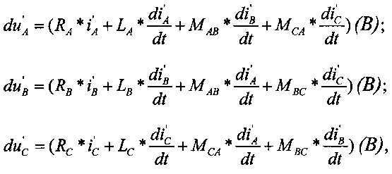
Падение напряжения в каждой фазе лини до точки короткого замыкания с двух концов линии (Фиг. 2.) можно записать как:The voltage drop in each phase of the line to the point of short circuit from two ends of the line (Fig. 2.) can be written as:


Упрощаем выражения 2Simplify

гдеWhere
![]()
![]()
![]()
![]()
![]()
![]()
![]()
![]()
![]()
![]()
![]()
![]()
После преобразования выражения (3) путем сложения трех уравнений получим выражение (1).After transforming the expression (3) by adding the three equations, we obtain the expression (1).
Для реализации способа по выражению (1) измеряют с двух концов линии (′ - один конец линии, ′′ - второй конец линии) мгновенные значения фазных токов i′A, i′B, i′C, i′′A, i′′B, i′′C и напряжений u′А, u′B, u′C, u′′A, u′′B, u′′C во время короткого замыкания, получают осциллограммы токов и напряжений, совмещают осциллограммы с двух концов линии по срезу начала короткого замыкания, выбирают на интервале двух-десяти периодов от начала короткого замыкания сечение на осциллограммах тока и напряжения фаз, снимают мгновенные значения напряжений u′А, u′B, u′C, u′′A, u′′B, u′′C и токов i′A, i′B, i′C, i′′A, i′′B, i′′ в сечении и в соседних точках, вычисляют в сечении производные от токов по времени diA′/dt, diB′/dt, diC/dt, diA′′/dt, diB′′/dt, diC′′/dt, формируют падение напряжения в проводе каждой фазы линии duA′, duB′, duC′ от токов одного конца линии:To implement the method according to expression (1), instantaneous values of phase currents i ′ A , i ′ B , i ′ C , i ′ ′ A , i ′ are measured from two ends of the line (′ is one end of the line, ′ ′ is the second end of the line) ′ B , i ′ ′ C and voltages u ′ A , u ′ B , u ′ C , u ′ ′ A , u ′ ′ B , u ′ ′ C during a short circuit, receive waveforms of currents and voltages, combine waveforms with two the ends of the line along the cut of the beginning of the short circuit, choose a section on the waveforms of the current and voltage of the phases in the interval of two to ten periods from the beginning of the short circuit, take the instantaneous voltage values u 'A, u' B, u 'C, u''A,u''B,u''C and a current i' A, i 'B, i' C, i '' A, i '' B, i ′ ′ in the cross section and at neighboring points, the derivatives of the currents with respect to time di A ′ / dt, di B ′ / dt, di C / dt, di A ′ ′ / dt, di B ′ ′ / dt, di C ′ ′ / dt, form a voltage drop in the wire of each phase of the line du A ′, du B ′, du C ′ from the currents of one end of the line:
![]()
![]()
![]()
![]()

формируют падение напряжения в проводе каждой фазы линии duA′′, duB′′, duC′′ от токов второго конца линии:form a voltage drop in the wire of each phase of the line du A ′ ′, du B ′ ′, du C ′ ′ from the currents of the second end of the line:
![]()
![]()
![]()
![]()

определяют относительное значение расстояния до места короткого замыкания n и физическое расстояние до места короткого замыкания со стороны конца линии с индексом ′ по выражению: l′=n·l. Физическое расстояние до места короткого замыкания со стороны конца линии с индексом ′′ определяют по выражению: l′′=(l-n)·l.determine the relative value of the distance to the place of short circuit n and the physical distance to the place of short circuit from the side of the end of the line with index ′ by the expression: l ′ = n · l. The physical distance to the short circuit from the end of the line with the index ″ is determined by the expression: l ″ = (l-n) · l.
Определение diA′/dt, diB′/dt, diC/dt, diA′′/dt, diB′′/dt, diC′/dt, производится одним из известных способов, например, на основе использования m-й i(mT) и предыдущей i(mT-T) выборки мгновенных значений токов в области сечения:The determination of di A ′ / dt, di B ′ / dt, di C / dt, di A ′ ′ / dt, di B ′ ′ / dt, di C ′ / dt, is performed using one of the known methods, for example, using m i (mT) and previous i (mT-T) samples of instantaneous current values in the cross-sectional area:
![]()
![]()
где i(mT) - последовательность мгновенных значений токов, взятых с осциллограмм (а), Т - период дискретизации (угол или время между двумя соседними точками осциллограммы).where i (mT) is the sequence of instantaneous values of currents taken from the waveforms (a), T is the sampling period (angle or time between two adjacent points of the waveform).
Предложенный способ также позволяет определять место короткого замыкания при других видах замыкания: двухфазном, двухфазном на землю, трехфазном.The proposed method also allows you to determine the location of a short circuit with other types of short circuits: two-phase, two-phase to ground, three-phase.
Определение места повреждения, выполненное по предложенной методике для схемы на фиг. 1, показало также полное отсутствие методической погрешности при наличии переходного сопротивления от 5 до 50 Ом и при изменениях нагрузочного режима в широких диапазонах. Погрешность отсутствует как при измерениях со стороны слабой, так и со стороны мощной системы.The determination of the location of damage made by the proposed method for the circuit of FIG. 1 also showed a complete absence of a methodological error in the presence of a transition resistance of 5 to 50 Ohms and with changes in the load regime in wide ranges. There is no error both in measurements from the weak and from the powerful system.
Таким образом, использование измеренных мгновенных значений токов и напряжений в фазах линии с учетом фазных и междуфазных параметров линии позволяет получить точные параметры линии, что при наличии точной синхронизации по времени при двухстороннем несинхронизированном замере за счет совмещения осциллограммы с двух концов линии по срезу начала короткого замыкания, чем достигается более точное определение расстояния до места короткого замыкания.Thus, the use of the measured instantaneous values of currents and voltages in the phases of the line, taking into account the phase and interphase parameters of the line, allows us to obtain accurate line parameters, which, if there is accurate time synchronization with two-way unsynchronized measurement, by combining the waveform from both ends of the line by cutting the beginning of a short circuit than a more accurate determination of the distance to the short circuit is achieved.
При совмещении осциллограмм с двух концов линии по срезу начала короткого замыкания определяется точный угол между напряжениями и токами по концам линии. Значение угла между напряжениями и токами по концам линии могут быть использованы для других целей, например для анализа режима другой части сети.When combining the waveforms from two ends of the line along the slice of the beginning of the short circuit, the exact angle between the voltages and currents at the ends of the line is determined. The angle between the voltages and currents at the ends of the line can be used for other purposes, for example, to analyze the mode of another part of the network.
Claims (1)
формируют падение напряжения в проводе каждой фазы линии

и определяют относительное значение расстояния до места короткого замыкания по выражению:

где n - относительное значение расстояния до места короткого замыкания;
фаз A, B, C с одного и второго концов линии, (А/с);
RA, RB, RC - активные фазные сопротивления линии (Ом);
LA, LB, LC - индуктивности фаз линии (Гн);
МАВ, МВC, MCA - взаимоиндукции между проводами фаз линии (Гн). A method for determining the location of a short circuit on an overhead power line with unsynchronized measurements at its two ends, having a length l, having complex phase conductors Z A = R A + jωL A , Z B = R B + jωL B , Z C = R C + jωL C , interphase complex resistances Z AB = R AB + jωL AB , Z BC = R AB + jωL AB , Z CA = R CA + jωL CA , connecting two power systems, in which they measure from two ends of the line (′ - one end lines, ′ ′ - the second end of the line) instantaneous values of phase currents
form a voltage drop in the wire of each phase of the line
and determine the relative value of the distance to the short circuit location by the expression:
where n is the relative value of the distance to the short circuit;
phases A, B, C from one and the second ends of the line, (A / s);
R A , R B , R C - phase active resistance of the line (Ohm);
L A , L B , L C - line phase inductance (H);
M AB , M BC , M CA - mutual induction between the wires of the phases of the line (GN).
Priority Applications (1)
| Application Number | Priority Date | Filing Date | Title |
|---|---|---|---|
| RU2015115191/28A RU2586453C1 (en) | 2015-04-22 | 2015-04-22 | Method of determining point of short-circuit on overhead power transmission line at non-synchronised measurements on both ends thereof |
Applications Claiming Priority (1)
| Application Number | Priority Date | Filing Date | Title |
|---|---|---|---|
| RU2015115191/28A RU2586453C1 (en) | 2015-04-22 | 2015-04-22 | Method of determining point of short-circuit on overhead power transmission line at non-synchronised measurements on both ends thereof |
Publications (1)
| Publication Number | Publication Date |
|---|---|
| RU2586453C1 true RU2586453C1 (en) | 2016-06-10 |
Family
ID=56115409
Family Applications (1)
| Application Number | Title | Priority Date | Filing Date |
|---|---|---|---|
| RU2015115191/28A RU2586453C1 (en) | 2015-04-22 | 2015-04-22 | Method of determining point of short-circuit on overhead power transmission line at non-synchronised measurements on both ends thereof |
Country Status (1)
| Country | Link |
|---|---|
| RU (1) | RU2586453C1 (en) |
Cited By (3)
| Publication number | Priority date | Publication date | Assignee | Title |
|---|---|---|---|---|
| RU2700370C1 (en) * | 2018-12-26 | 2019-09-16 | федеральное государственное бюджетное образовательное учреждение высшего образования "Ивановский государственный энергетический университет имени В.И. Ленина" (ИГЭУ) | Method for remote determination of short-circuit point |
| RU2731657C1 (en) * | 2019-12-02 | 2020-09-07 | федеральное государственное бюджетное образовательное учреждение высшего образования "Ивановский государственный энергетический университет имени В.И. Ленина" (ИГЭУ) | Method for remote determination of short-circuit place on power transmission line |
| RU2793555C1 (en) * | 2022-06-22 | 2023-04-04 | федеральное государственное бюджетное образовательное учреждение высшего образования "Нижегородский государственный технический университет им. Р.Е. Алексеева" (НГТУ) | Method for determining location of a short circuit on an overhead power line with unsynchronized measurements from its two ends |
Citations (6)
| Publication number | Priority date | Publication date | Assignee | Title |
|---|---|---|---|---|
| WO2003044547A1 (en) * | 2001-11-23 | 2003-05-30 | Abb Ab | Fault location using measurements from two ends of a line |
| US20080150544A1 (en) * | 2006-12-22 | 2008-06-26 | Premerlani William J | Multi-ended fault location system |
| EP1924863B1 (en) * | 2005-09-14 | 2014-01-15 | ABB Technology AG | A method for fault location in electric power lines |
| RU2508556C1 (en) * | 2012-10-24 | 2014-02-27 | Федеральное государственное бюджетное образовательное учреждение высшего профессионального образования "Иркутский государственный технический университет" (ФГБОУ ВПО "ИрГТУ") | Method for determination of short-circuit place on overhead transmission line under nonsynchronised measurements on its both ends |
| RU2526095C2 (en) * | 2009-10-09 | 2014-08-20 | Александр Никандорович Висящев | Method to determine area of damage on overhead power transmission lines (versions) |
| RU2531769C2 (en) * | 2013-07-23 | 2014-10-27 | Степан Георгиевич Тигунцев | Method for determination of short circuit spot on overhead power transmission line against measurements at two ends thereof |
-
2015
- 2015-04-22 RU RU2015115191/28A patent/RU2586453C1/en not_active IP Right Cessation
Patent Citations (6)
| Publication number | Priority date | Publication date | Assignee | Title |
|---|---|---|---|---|
| WO2003044547A1 (en) * | 2001-11-23 | 2003-05-30 | Abb Ab | Fault location using measurements from two ends of a line |
| EP1924863B1 (en) * | 2005-09-14 | 2014-01-15 | ABB Technology AG | A method for fault location in electric power lines |
| US20080150544A1 (en) * | 2006-12-22 | 2008-06-26 | Premerlani William J | Multi-ended fault location system |
| RU2526095C2 (en) * | 2009-10-09 | 2014-08-20 | Александр Никандорович Висящев | Method to determine area of damage on overhead power transmission lines (versions) |
| RU2508556C1 (en) * | 2012-10-24 | 2014-02-27 | Федеральное государственное бюджетное образовательное учреждение высшего профессионального образования "Иркутский государственный технический университет" (ФГБОУ ВПО "ИрГТУ") | Method for determination of short-circuit place on overhead transmission line under nonsynchronised measurements on its both ends |
| RU2531769C2 (en) * | 2013-07-23 | 2014-10-27 | Степан Георгиевич Тигунцев | Method for determination of short circuit spot on overhead power transmission line against measurements at two ends thereof |
Cited By (4)
| Publication number | Priority date | Publication date | Assignee | Title |
|---|---|---|---|---|
| RU2700370C1 (en) * | 2018-12-26 | 2019-09-16 | федеральное государственное бюджетное образовательное учреждение высшего образования "Ивановский государственный энергетический университет имени В.И. Ленина" (ИГЭУ) | Method for remote determination of short-circuit point |
| RU2731657C1 (en) * | 2019-12-02 | 2020-09-07 | федеральное государственное бюджетное образовательное учреждение высшего образования "Ивановский государственный энергетический университет имени В.И. Ленина" (ИГЭУ) | Method for remote determination of short-circuit place on power transmission line |
| RU2793555C1 (en) * | 2022-06-22 | 2023-04-04 | федеральное государственное бюджетное образовательное учреждение высшего образования "Нижегородский государственный технический университет им. Р.Е. Алексеева" (НГТУ) | Method for determining location of a short circuit on an overhead power line with unsynchronized measurements from its two ends |
| RU2813463C1 (en) * | 2023-04-04 | 2024-02-12 | федеральное государственное бюджетное образовательное учреждение высшего образования "Нижегородский государственный технический университет им. Р.Е. Алексеева" (НГТУ) | Method of determining short circuit point on overhead power transmission line with unsynchronized measurements from its two ends |
Similar Documents
| Publication | Publication Date | Title |
|---|---|---|
| RU2508556C1 (en) | Method for determination of short-circuit place on overhead transmission line under nonsynchronised measurements on its both ends | |
| RU2539830C2 (en) | Method for determining place of damage in air and cable lines of power transmission in networks with insulated neutral | |
| RU2531769C2 (en) | Method for determination of short circuit spot on overhead power transmission line against measurements at two ends thereof | |
| Benato et al. | Zero sequence behaviour of a double-circuit overhead line | |
| RU2586453C1 (en) | Method of determining point of short-circuit on overhead power transmission line at non-synchronised measurements on both ends thereof | |
| WO2019166903A1 (en) | Method and device for fault location in a two-terminal transmission system | |
| RU2610852C1 (en) | Method of short circuit place determination in overhead power transmission line with calculated synchronisation of measurements at its both ends | |
| CN107037324B (en) | Fault location method free from transition resistance based on single-end electric quantity | |
| EP3185025B1 (en) | Electrical fault location method | |
| Jia et al. | Impedance-based earth fault location for a non-directly grounded distribution systems | |
| CN104330705B (en) | Circuit inter-phase fault single-end ranging based on phase-to phase fault location factor | |
| RU2505827C1 (en) | Method of determining point of short-circuit on overhead power line from measurements at two ends thereof (versions) | |
| RU2605491C1 (en) | Method of determining short circuit location on overhead transmission line by measurements from two ends of line considering difference in longitudinal and transverse phase and interphase parameters of line | |
| RU2615150C1 (en) | Method of determining the short circuit spot on multi-chain with earth-wires, grounded at anchor supports, three-phase electric transmission air-line with distributed parameters | |
| CN104316842B (en) | Line phase fault single-ended distance measurement method by means of phase fault position factor phase characteristic | |
| RU2605558C1 (en) | Method of determining short circuit location on overhead transmission line with lightning protection cable by measurements from two ends of line considering difference in longitudinal and transverse phase and interphase parameters of line | |
| RU2593409C1 (en) | Method of determining location of short circuit at long power line with spur line | |
| RU2623180C1 (en) | Method of determining the short circuit spot on multi-chain with earth-wires, grounded at anchor supports, three-phase electric transmission air-line with distributed parameters | |
| RU2485531C2 (en) | Method for determination of short circuit spot on overhead power transmission line from two ends thereof (versions) | |
| Eng et al. | Single-ended traveling wave based fault location on two terminal transmission lines | |
| RU2620193C1 (en) | Method of determining short-short location in overhead power line with distributed parameters | |
| RU2753838C1 (en) | Method for determining the distance to ground fault locations on two power transmission lines in networks with low ground fault currents | |
| Kumar et al. | A novel technique for impedance relay to locate fault in long transmission line | |
| RU2750421C1 (en) | Method for determining distance to places of double earth faults on power lines in networks with low earth fault currents | |
| KR101368907B1 (en) | Segmentized hybrid state estimation system based on synchrophasor measurement information, and method of estimating hybrid state of segmentized power grid |
Legal Events
| Date | Code | Title | Description |
|---|---|---|---|
| MM4A | The patent is invalid due to non-payment of fees |
Effective date: 20200423 |