RU2396548C2 - Light guide test sensor for determining analysed substance in fluid sample (versions) and method of making said sensor (versions) - Google Patents
Light guide test sensor for determining analysed substance in fluid sample (versions) and method of making said sensor (versions) Download PDFInfo
- Publication number
- RU2396548C2 RU2396548C2 RU2007104049/28A RU2007104049A RU2396548C2 RU 2396548 C2 RU2396548 C2 RU 2396548C2 RU 2007104049/28 A RU2007104049/28 A RU 2007104049/28A RU 2007104049 A RU2007104049 A RU 2007104049A RU 2396548 C2 RU2396548 C2 RU 2396548C2
- Authority
- RU
- Russia
- Prior art keywords
- membrane
- light guide
- reagent
- strip
- light
- Prior art date
Links
Images
Classifications
-
- G—PHYSICS
- G01—MEASURING; TESTING
- G01N—INVESTIGATING OR ANALYSING MATERIALS BY DETERMINING THEIR CHEMICAL OR PHYSICAL PROPERTIES
- G01N21/00—Investigating or analysing materials by the use of optical means, i.e. using sub-millimetre waves, infrared, visible or ultraviolet light
- G01N21/75—Systems in which material is subjected to a chemical reaction, the progress or the result of the reaction being investigated
- G01N21/77—Systems in which material is subjected to a chemical reaction, the progress or the result of the reaction being investigated by observing the effect on a chemical indicator
- G01N21/78—Systems in which material is subjected to a chemical reaction, the progress or the result of the reaction being investigated by observing the effect on a chemical indicator producing a change of colour
-
- G—PHYSICS
- G01—MEASURING; TESTING
- G01N—INVESTIGATING OR ANALYSING MATERIALS BY DETERMINING THEIR CHEMICAL OR PHYSICAL PROPERTIES
- G01N21/00—Investigating or analysing materials by the use of optical means, i.e. using sub-millimetre waves, infrared, visible or ultraviolet light
- G01N21/17—Systems in which incident light is modified in accordance with the properties of the material investigated
- G01N21/25—Colour; Spectral properties, i.e. comparison of effect of material on the light at two or more different wavelengths or wavelength bands
- G01N21/251—Colorimeters; Construction thereof
-
- G—PHYSICS
- G01—MEASURING; TESTING
- G01N—INVESTIGATING OR ANALYSING MATERIALS BY DETERMINING THEIR CHEMICAL OR PHYSICAL PROPERTIES
- G01N21/00—Investigating or analysing materials by the use of optical means, i.e. using sub-millimetre waves, infrared, visible or ultraviolet light
- G01N21/17—Systems in which incident light is modified in accordance with the properties of the material investigated
- G01N21/47—Scattering, i.e. diffuse reflection
- G01N21/4738—Diffuse reflection, e.g. also for testing fluids, fibrous materials
- G01N21/474—Details of optical heads therefor, e.g. using optical fibres
-
- G—PHYSICS
- G01—MEASURING; TESTING
- G01N—INVESTIGATING OR ANALYSING MATERIALS BY DETERMINING THEIR CHEMICAL OR PHYSICAL PROPERTIES
- G01N21/00—Investigating or analysing materials by the use of optical means, i.e. using sub-millimetre waves, infrared, visible or ultraviolet light
- G01N21/75—Systems in which material is subjected to a chemical reaction, the progress or the result of the reaction being investigated
- G01N21/77—Systems in which material is subjected to a chemical reaction, the progress or the result of the reaction being investigated by observing the effect on a chemical indicator
- G01N21/7703—Systems in which material is subjected to a chemical reaction, the progress or the result of the reaction being investigated by observing the effect on a chemical indicator using reagent-clad optical fibres or optical waveguides
- G01N2021/7706—Reagent provision
- G01N2021/772—Tip coated light guide
-
- G—PHYSICS
- G01—MEASURING; TESTING
- G01N—INVESTIGATING OR ANALYSING MATERIALS BY DETERMINING THEIR CHEMICAL OR PHYSICAL PROPERTIES
- G01N21/00—Investigating or analysing materials by the use of optical means, i.e. using sub-millimetre waves, infrared, visible or ultraviolet light
- G01N21/75—Systems in which material is subjected to a chemical reaction, the progress or the result of the reaction being investigated
- G01N21/77—Systems in which material is subjected to a chemical reaction, the progress or the result of the reaction being investigated by observing the effect on a chemical indicator
- G01N2021/7769—Measurement method of reaction-produced change in sensor
- G01N2021/7773—Reflection
-
- G—PHYSICS
- G01—MEASURING; TESTING
- G01N—INVESTIGATING OR ANALYSING MATERIALS BY DETERMINING THEIR CHEMICAL OR PHYSICAL PROPERTIES
- G01N21/00—Investigating or analysing materials by the use of optical means, i.e. using sub-millimetre waves, infrared, visible or ultraviolet light
- G01N21/62—Systems in which the material investigated is excited whereby it emits light or causes a change in wavelength of the incident light
- G01N21/63—Systems in which the material investigated is excited whereby it emits light or causes a change in wavelength of the incident light optically excited
- G01N21/64—Fluorescence; Phosphorescence
- G01N21/6486—Measuring fluorescence of biological material, e.g. DNA, RNA, cells
-
- G—PHYSICS
- G01—MEASURING; TESTING
- G01N—INVESTIGATING OR ANALYSING MATERIALS BY DETERMINING THEIR CHEMICAL OR PHYSICAL PROPERTIES
- G01N21/00—Investigating or analysing materials by the use of optical means, i.e. using sub-millimetre waves, infrared, visible or ultraviolet light
- G01N21/75—Systems in which material is subjected to a chemical reaction, the progress or the result of the reaction being investigated
- G01N21/77—Systems in which material is subjected to a chemical reaction, the progress or the result of the reaction being investigated by observing the effect on a chemical indicator
- G01N21/78—Systems in which material is subjected to a chemical reaction, the progress or the result of the reaction being investigated by observing the effect on a chemical indicator producing a change of colour
- G01N21/80—Indicating pH value
-
- G—PHYSICS
- G01—MEASURING; TESTING
- G01N—INVESTIGATING OR ANALYSING MATERIALS BY DETERMINING THEIR CHEMICAL OR PHYSICAL PROPERTIES
- G01N2201/00—Features of devices classified in G01N21/00
- G01N2201/08—Optical fibres; light guides
-
- G—PHYSICS
- G01—MEASURING; TESTING
- G01N—INVESTIGATING OR ANALYSING MATERIALS BY DETERMINING THEIR CHEMICAL OR PHYSICAL PROPERTIES
- G01N33/00—Investigating or analysing materials by specific methods not covered by groups G01N1/00 - G01N31/00
- G01N33/48—Biological material, e.g. blood, urine; Haemocytometers
- G01N33/50—Chemical analysis of biological material, e.g. blood, urine; Testing involving biospecific ligand binding methods; Immunological testing
- G01N33/58—Chemical analysis of biological material, e.g. blood, urine; Testing involving biospecific ligand binding methods; Immunological testing involving labelled substances
- G01N33/582—Chemical analysis of biological material, e.g. blood, urine; Testing involving biospecific ligand binding methods; Immunological testing involving labelled substances with fluorescent label
-
- G—PHYSICS
- G01—MEASURING; TESTING
- G01N—INVESTIGATING OR ANALYSING MATERIALS BY DETERMINING THEIR CHEMICAL OR PHYSICAL PROPERTIES
- G01N33/00—Investigating or analysing materials by specific methods not covered by groups G01N1/00 - G01N31/00
- G01N33/48—Biological material, e.g. blood, urine; Haemocytometers
- G01N33/50—Chemical analysis of biological material, e.g. blood, urine; Testing involving biospecific ligand binding methods; Immunological testing
- G01N33/58—Chemical analysis of biological material, e.g. blood, urine; Testing involving biospecific ligand binding methods; Immunological testing involving labelled substances
- G01N33/583—Chemical analysis of biological material, e.g. blood, urine; Testing involving biospecific ligand binding methods; Immunological testing involving labelled substances with non-fluorescent dye label
-
- Y—GENERAL TAGGING OF NEW TECHNOLOGICAL DEVELOPMENTS; GENERAL TAGGING OF CROSS-SECTIONAL TECHNOLOGIES SPANNING OVER SEVERAL SECTIONS OF THE IPC; TECHNICAL SUBJECTS COVERED BY FORMER USPC CROSS-REFERENCE ART COLLECTIONS [XRACs] AND DIGESTS
- Y10—TECHNICAL SUBJECTS COVERED BY FORMER USPC
- Y10T—TECHNICAL SUBJECTS COVERED BY FORMER US CLASSIFICATION
- Y10T156/00—Adhesive bonding and miscellaneous chemical manufacture
- Y10T156/12—Surface bonding means and/or assembly means with cutting, punching, piercing, severing or tearing
- Y10T156/1313—Cutting element simultaneously bonds [e.g., cut seaming]
-
- Y—GENERAL TAGGING OF NEW TECHNOLOGICAL DEVELOPMENTS; GENERAL TAGGING OF CROSS-SECTIONAL TECHNOLOGIES SPANNING OVER SEVERAL SECTIONS OF THE IPC; TECHNICAL SUBJECTS COVERED BY FORMER USPC CROSS-REFERENCE ART COLLECTIONS [XRACs] AND DIGESTS
- Y10—TECHNICAL SUBJECTS COVERED BY FORMER USPC
- Y10T—TECHNICAL SUBJECTS COVERED BY FORMER US CLASSIFICATION
- Y10T436/00—Chemistry: analytical and immunological testing
- Y10T436/14—Heterocyclic carbon compound [i.e., O, S, N, Se, Te, as only ring hetero atom]
- Y10T436/142222—Hetero-O [e.g., ascorbic acid, etc.]
- Y10T436/143333—Saccharide [e.g., DNA, etc.]
- Y10T436/144444—Glucose
Abstract
Description
Область техникиTechnical field
Настоящее изобретение относится к испытательным системам для определения концентрации исследуемого вещества в образце флюида, в целом, и к оптическому тестовому датчику, предназначенному для определения концентрации аналита (исследуемого вещества) в биологической жидкости, в частности.The present invention relates to test systems for determining the concentration of an analyte in a fluid sample in general, and to an optical test sensor for determining the concentration of analyte (analyte) in a biological fluid, in particular.
Уровень техникиState of the art
Часто возникает необходимость в быстром получении пробы крови и проведении ее анализа. Один из примеров такого отбора крови связан с системой мониторинга уровня глюкозы в крови, к которой пользователь вынужден часто прибегать.Often there is a need to quickly obtain a blood sample and conduct its analysis. One example of such a blood sampling is associated with a blood glucose monitoring system that the user often has to resort to.
Один из способов контроля за уровнем глюкозы в крови человека предполагает использование портативного карманного тестирующего устройства для определения уровня глюкозы в крови (глюкометра). Портативность таких устройств позволяет пользователю удобным образом проверять уровень глюкозы в крови практически в любом месте. Некоторые из этих устройств имеют функцию колориметрического анализа, при котором специальное вещество вступает в реакцию с кровью, и цвет продуктов реакции указывает на концентрацию глюкозы. Являющийся частью такого тестирующего устройства оптический инструмент выполняет считывание результатов колориметрической реакции.One way to control the level of glucose in the blood of a person involves the use of a portable handheld testing device to determine the level of glucose in the blood (glucometer). The portability of such devices allows the user to conveniently check the level of glucose in the blood almost anywhere. Some of these devices have a colorimetric analysis function in which a special substance reacts with the blood, and the color of the reaction products indicates the concentration of glucose. As part of such a testing device, an optical instrument reads the results of a colorimetric reaction.
Основным недостатком оптических инструментов, предназначенных для считывания результатов колориметрических реакций, является их загрязнение биологическим жидкостями. Загрязнение происходит в случае, когда биологическая жидкость из предыдущей пробы контактирует с оптическими компонентами, а затем не удаляется перед проведением анализа следующей пробы. Наличие биологической жидкости из предыдущей пробы может снизить точность анализа текущей пробы в результате смешивания с текущей пробой или перекрывания части оптического компонента, препятствующего точному считыванию результата. Таким образом, существует необходимость в устройстве, где оптические компоненты были бы изолированы от биологической жидкости.The main disadvantage of optical instruments designed to read the results of colorimetric reactions is their contamination with biological fluids. Contamination occurs when biological fluid from a previous sample comes into contact with optical components, and then is not removed before analyzing the next sample. The presence of biological fluid from a previous sample can reduce the accuracy of the analysis of the current sample as a result of mixing with the current sample or overlapping part of the optical component, which prevents accurate reading of the result. Thus, there is a need for a device where the optical components are isolated from biological fluid.
Один из способов изготовления обычных тестовых датчиков с использованием традиционной технологии предполагает вырезание полоски мембраны, покрытой реагентом, и полоски сетчатого слоя требуемого размера с последующим прикреплением к датчику. Небольшой размер предварительно вырезанного слоя покрытой реагентом мембраны и сетчатого слоя делает процесс производства сложным, трудоемким и требующим значительного времени. Таким образом, желательной была бы разработка способа изготовления тестового датчика, который был бы более простым в реализации.One of the methods for manufacturing conventional test sensors using traditional technology involves cutting a strip of membrane coated with a reagent and a strip of mesh layer of the required size, followed by attachment to the sensor. The small size of the pre-cut layer of the reagent-coated membrane and the mesh layer makes the manufacturing process complex, time-consuming and time consuming. Thus, it would be desirable to develop a method of manufacturing a test sensor that would be simpler to implement.
Сущность изобретенияSUMMARY OF THE INVENTION
В соответствии с одним из вариантов осуществления настоящего изобретения оптический световодный датчик включает световод, покрытую реагентом мембрану и сетчатый слой. Световод имеет входную концевую часть и выходную концевую часть. Покрытая реагентом мембрана находится на выходной концевой части световода. Реагент способен вступать в реакцию с пробой флюида для индикации уровня исследуемого вещества в пробе. Сетчатый слой прикреплен к мембране.According to one embodiment of the present invention, the optical light guide sensor includes a light guide, a reagent-coated membrane and a mesh layer. The light guide has an input end part and an output end part. The reagent-coated membrane is located at the output end of the fiber. The reagent is able to react with a sample of fluid to indicate the level of the analyte in the sample. The mesh layer is attached to the membrane.
В соответствии с другим вариантом осуществления настоящего изобретения оптический световодный тестовый датчик включает световод, сетчатый слой и покрытую реагентом мембрану. Световод имеет входную и выходную концевые части. На выходной концевой части световода также предусмотрены выступы. Сетчатый слой прикреплен к выступам на световоде. Между выходной концевой частью световода и сетчатым слоем образуется зазор. Зазор выполнен с возможностью втягивания в него пробы при использовании тестового датчика. Покрытая реагентом мембрана прикреплена к сетчатому слою, находящемуся на выходной концевой части световода. Реагент способен вступать в реакцию с пробой флюида для индикации уровня исследуемого вещества в пробе.According to another embodiment of the present invention, the optical light guide test sensor includes a light guide, a mesh layer, and a reagent-coated membrane. The fiber has an input and output end parts. Lugs are also provided at the output end of the fiber. The mesh layer is attached to the protrusions on the fiber. Between the output end of the fiber and the mesh layer, a gap is formed. The gap is made with the possibility of drawing samples into it when using a test sensor. The reagent-coated membrane is attached to the mesh layer located at the output end of the fiber. The reagent is able to react with a sample of fluid to indicate the level of the analyte in the sample.
В соответствии с одним способом данного изобретения производится анализ уровня исследуемого вещества в биологической жидкости. Действия способа обеспечиваются посредством световодного тестового датчика, который включает световод, покрытую реагентом мембрану и сетчатый слой. Считывающая головка выполнена с возможностью работы совместно со световодным тестовым датчиком для определения уровня исследуемого вещества в биологической жидкости. Пользователь выполняет прокол на участке тела для получения пробы флюида. Он отбирает пробу крови с помощью покрытой реагентом мембраны и сетчатого слоя световодного тестового датчика. Пользователь размещает световодный тестовый датчик с отобранной пробой таким образом, чтобы считывающая головка оказалась в позиции для осуществления анализа образца. Согласно способу производится измерение света, отраженного от пробы.In accordance with one method of the present invention, an analysis is made of the level of a test substance in a biological fluid. The actions of the method are provided by means of a light guide test sensor, which includes a light guide, a reagent-coated membrane and a mesh layer. The reading head is configured to work in conjunction with a light guide test sensor to determine the level of the test substance in the biological fluid. The user performs a puncture on a portion of the body to obtain a fluid sample. He takes a blood sample using a reagent-coated membrane and a mesh layer of a light guide test sensor. The user places the light guide test probe with the sample taken so that the read head is in position for sample analysis. According to the method, a measurement is made of the light reflected from the sample.
В соответствии с другим способом данного изобретения изготавливают световодный тестовый датчик. Предусматривают множество световодов с выступами и полоску покрытой реагентом мембраны. В соответствии со способом полоску покрытой реагентом мембраны помещают на множество световодов таким образом, чтобы их выступы контактировали с полоской покрытой реагентом мембраны. С помощью ультразвуковой сварки расплавляют выступы для вырезания и прикрепления полоски покрытой реагентом мембраны к множеству световодов, при этом вырезание и прикрепление покрытой реагентом мембраны происходят приблизительно одновременно. В процессе резки и прикрепления световод играет роль матрицы.In accordance with another method of the present invention, a light guide test sensor is manufactured. A plurality of optical fibers with protrusions and a strip of reagent-coated membrane are provided. According to the method, a strip of reagent-coated membrane is placed on a plurality of optical fibers so that their protrusions contact a strip of reagent-coated membrane. Using ultrasonic welding, the projections for melting and attaching a strip of the reagent-coated membrane to a plurality of optical fibers are melted and the cutting and attachment of the reagent-coated membrane occur approximately simultaneously. In the process of cutting and attachment, the fiber plays the role of a matrix.
В соответствии с другим способом данного изобретения изготавливают световодный тестовый датчик. Предусматривают множество световодов с выступами и полоску покрытой реагентом мембраны. Также обеспечивают полоску сетчатого слоя. В соответствии со способом полоску мембраны и сетчатую полоску помещают на множество световодов таким образом, чтобы их выступы контактировали с полоской мембраны, а сетчатая полоска контактировала с полоской мембраны. С помощью ультразвуковой сварки расплавляют выступы для вырезания и прикрепления полоски покрытой реагентом мембраны и полоски сетчатого слоя к множеству световодов. При этом вырезание и прикрепление покрытой реагентом мембраны и сетчатого слоя происходят приблизительно одновременно. В процессе резки и прикрепления световод играет роль матрицы.In accordance with another method of the present invention, a light guide test sensor is manufactured. A plurality of optical fibers with protrusions and a strip of reagent-coated membrane are provided. Also provide a strip of mesh layer. According to the method, a membrane strip and a mesh strip are placed on a plurality of optical fibers so that their protrusions are in contact with the membrane strip and the mesh strip is in contact with the membrane strip. Using ultrasonic welding, the projections for melting and attaching a strip of a reagent-coated membrane and a strip of mesh layer to a plurality of optical fibers are melted. In this case, the cutting and attachment of the reagent-coated membrane and the mesh layer occur approximately simultaneously. In the process of cutting and attachment, the fiber plays the role of a matrix.
В соответствии с еще одним способом данного изобретения изготавливают световодный тестовый датчик. Предусматривают множество световодов с клеящим элементом на одной концевой части и предусматривают полоску покрытой реагентом мембраны. Полоска мембраны контактирует с множеством световодов таким образом, что полоска мембраны контактирует с клеящими элементами. Вырезание и прикрепление полоски мембраны к множеству световодов осуществляется при помощи пуансона, при этом световоды играют роль матрицы. Мембрана прикрепляется к световоду посредством клеящего элемента. При этом вырезание и прикрепление мембраны к световоду происходит приблизительно одновременно.In accordance with another method of the present invention, a light guide test sensor is manufactured. A plurality of optical fibers with an adhesive element are provided at one end portion and a strip of reagent-coated membrane is provided. The strip of membrane is in contact with a plurality of optical fibers in such a way that the strip of membrane is in contact with adhesive elements. Cutting and attaching the strip of membrane to a variety of optical fibers is carried out using a punch, while the optical fibers play the role of a matrix. The membrane is attached to the fiber by means of an adhesive element. In this case, the cutting and attachment of the membrane to the fiber occurs approximately simultaneously.
В соответствии с еще одним вариантом осуществления настоящего изобретения оптический диффузный световодный датчик включает световод подсветки, имеющий входную и выходную концевые части. Датчик также имеет детекторный световод с входными и выходными концевыми частями, причем его входная концевая часть находится в непосредственной близости от выходной концевой части световода подсветки. Покрытая реагентом мембрана прикреплена к выходной концевой части световода подсветки и входной концевой части детекторного световода. Мембрана освещается светом, исходящим из выходной концевой части световода подсветки. Сетчатый слой прикреплен к покрытой реагентом мембране и непосредственно контактирует с ней.In accordance with yet another embodiment of the present invention, an optical diffuse light guide sensor includes a backlight fiber having input and output end parts. The sensor also has a detector fiber with input and output end parts, and its input end part is in close proximity to the output end part of the backlight fiber. The reagent-coated membrane is attached to the output end of the backlight and the input end of the detector. The membrane is illuminated by light emanating from the output end of the backlight. The mesh layer is attached to the reagent-coated membrane and is in direct contact with it.
В соответствии с еще одним вариантом осуществления данного изобретения предусмотрена система оптического световодного датчика отраженного света, включающая считывающую головку, выполненную с возможностью определения количества исследуемого вещества в биологической пробе. Считывающая головка содержит источник света для освещения пробы, а также оптические средства подсветки, проводящие свет через нее. Считывающая головка также включает светоделитель, направляющий свет, отраженный от пробы, в оптические средства отражения. Оптические средства отражения направляют отраженный свет в детектор, который вырабатывает выходной сигнал, соответствующий поступающему в него свету. Этот выходной сигнал пропорционален количеству поступающего света. В световодный тестовый датчик поступает анализируемая проба. Световодный тестовый датчик содержит световод с входными и выходными концевыми частями, а также покрытую реагентом мембрану и сетчатый слой, прикрепленные к выходной концевой части световода.In accordance with another embodiment of the present invention, there is provided a system of an optical light guide of the reflected light sensor, including a read head configured to determine the amount of test substance in a biological sample. The reading head contains a light source for illuminating the sample, as well as optical illumination means that conduct light through it. The read head also includes a beam splitter, directing the light reflected from the sample into the optical reflection means. Optical reflection means direct reflected light to a detector, which generates an output signal corresponding to the light entering it. This output signal is proportional to the amount of incoming light. The analyzed sample enters the light guide test sensor. The light guide test sensor comprises a light guide with input and output end parts, as well as a reagent-coated membrane and a mesh layer attached to the output end of the light guide.
Краткое описание чертежейBrief Description of the Drawings
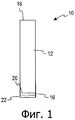
На фиг.1 приведен вид в разрезе световодного датчика в соответствии с вариантом осуществления настоящего изобретения;1 is a cross-sectional view of a light guide sensor in accordance with an embodiment of the present invention;
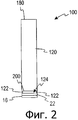
на фиг.2 приведен вид в разрезе световодного датчика в соответствии с другим вариантом осуществления настоящего изобретения;2 is a sectional view of a light guide sensor in accordance with another embodiment of the present invention;
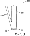
на фиг.3 приведена функциональная блок-схема тестового датчика согласно фиг.1 с головкой считывания согласно одному из вариантов осуществления настоящего изобретения;figure 3 shows a functional block diagram of a test sensor according to figure 1 with a read head according to one embodiment of the present invention;
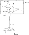
на фиг.4 приведен схематический вид способа изготовления световодного датчика в соответствии с вариантом осуществления настоящего изобретения;FIG. 4 is a schematic view of a method for manufacturing a light guide sensor in accordance with an embodiment of the present invention;
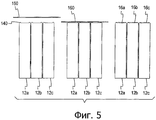
на фиг.5 приведен схематический вид способа изготовления световодного датчика в соответствии с другим вариантом осуществления настоящего изобретения;figure 5 shows a schematic view of a method of manufacturing a light guide sensor in accordance with another embodiment of the present invention;
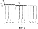
на фиг.6 приведен схематический вид способа изготовления световодного датчика в соответствии с еще одним вариантом осуществления настоящего изобретения; иFIG. 6 is a schematic view of a method for manufacturing a light guide sensor in accordance with another embodiment of the present invention; and
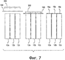
на фиг.7 приведен вид в разрезе световодного датчика в соответствии с другим вариантом осуществления настоящего изобретения.7 is a sectional view of a light guide sensor in accordance with another embodiment of the present invention.
В то время как в изобретение могут быть внесены различные модификации или использованы альтернативные формы в соответствии с ним, на чертежах в качестве примера изображены конкретные варианты осуществления изобретения, которые будут подробно описаны ниже. Однако следует понимать, что они не ограничивают данное изобретение конкретными формами, описанными здесь, а наоборот, изобретение охватывает все модификации, эквиваленты и альтернативы, соответствующие его сущности и объему, определенным в прилагаемой формуле изобретения.While various modifications may be made to the invention or alternative forms used in accordance with it, the drawings show by way of example specific embodiments of the invention, which will be described in detail below. However, it should be understood that they do not limit the invention to the specific forms described herein, but rather that the invention covers all modifications, equivalents, and alternatives corresponding to its essence and scope as defined in the attached claims.
Подробное описание изображенных на чертежахDetailed Description of Drawings
вариантов осуществления изобретенияembodiments of the invention
Рассмотрим чертежи и, в первую очередь, фиг.1, где изображен световодный тестовый датчик 10 в соответствии с одним вариантом осуществления настоящего изобретения. В одном варианте осуществления изобретения световодный тестовый датчик 10 используется с портативным карманным прибором для измерения концентрации глюкозы в жидкости организма (например, крови, тканевой жидкости) пациента. Конкретнее, световодный тестовый датчик 10 согласно настоящему изобретению используется для измерения колориметрической реакции, в которую вступает реагент с заданным анализируемым веществом. Световодный тестовый датчик 10 обеспечивает подсветку и принимает свет, отраженный от пробы флюида организма, реагирующей с покрытой реагентом мембраной 16 на одной концевой части световода 12. Более конкретно, тестовый датчик 10 используется для измерения степени изменения цвета реагента в результате реакции. Степень изменения цвета реагента указывает на концентрацию исследуемого вещества (например, глюкозы, фруктозоамина и т.д.) в жидкости организма. Колориметрическое тестирование подробно описано в патентах США №№6,181,417 В1 "Photometric Readhead with Light Shaping Plate" ("Фотометрическая считывающая головка со светоформирующей пластиной"); 5,518,689 "Diffuse Light Reflectance Readhead" ("Считывающая головка в системе с отражением диффузного света"); и 5,611,999 "Diffuse Light Reflectance Readhead" ("Считывающая головка в системе с отражением диффузного света"); каждый из которых включен сюда во всей своей полноте путем ссылки.Consider the drawings and, in particular, FIG. 1, which shows a light
В соответствии с одним вариантом осуществления настоящего изобретения световодный тестовый датчик 10 включает световод 12, покрытую реагентом мембрану 16 и сетчатый слой 22. Световод 12 может быть запрессован с оптически прозрачным материалом, например акрилом. В других вариантах осуществления световод 12 запрессован с другими оптически прозрачными материалами, например поликарбонатом или полиэстером.In accordance with one embodiment of the present invention, the light
В соответствии с одним вариантом осуществления свет от источника света распространяется через световод 12 посредством полного внутреннего отражения. Свет, направленный через световод 12, подлежит считыванию посредством считывающей головки. Световод 12 способен подавать на свою выходную концевую часть 20 значительное количество света, поступившего на его входную концевую часть 18 от источника света. В соответствии с одним вариантом осуществления настоящего изобретения световод 12 имеет квадратное поперечное сечение приблизительно 2,3 мм х 2,3 мм и длину приблизительно 5 см. Квадратное поперечное сечение позволяет объединять подсветку и отраженный свет, таким образом, сводя к минимуму влияние несовемещений и отклонений в процессе производства. Световод 12 проводит свет от источника света к покрытой реагентом мембране 16 на выходной концевой части 20 световода 12.In accordance with one embodiment, the light from the light source is propagated through the
В альтернативном варианте осуществления настоящего изобретения световод представляет собой волновод с прозрачной сердцевиной и оболочкой с более высоким показателем преломления. Также рассматривается вариант, когда световод является полым волноводом или имеет покрытие из поглощающих или отражающих слоев, улучшающих рабочие характеристики датчика.In an alternative embodiment of the present invention, the light guide is a waveguide with a transparent core and a cladding with a higher refractive index. An option is also considered when the fiber is a hollow waveguide or has a coating of absorbing or reflecting layers that improve the performance of the sensor.
В соответствии с другим вариантом осуществления настоящего изобретения форма поперечного сечения световода может представлять собой любой многоугольник с четным числом конгруентных сторон.In accordance with another embodiment of the present invention, the cross-sectional shape of the fiber can be any polygon with an even number of congruent sides.
В еще одном варианте осуществления данного изобретения световод имеет плавно сужающееся поперечное сечение таким образом, что площадь поперечного сечения на входном конце больше, чем на выходном.In yet another embodiment of the invention, the light guide has a smoothly tapering cross-section so that the cross-sectional area at the input end is larger than at the output.
Покрытая реагентом мембрана 16 присоединена к световоду 12. В соответствии с одним вариантом осуществления изобретения покрытая реагентом мембрана 16 содержит фермент, такой как глюкозооксидаза, способный катализировать реакцию окисления глюкозы до глюконовой кислоты и пероксида водорода, и вещество, обладающее перокисляющим действием, способное катализировать окисление индикатора. Покрытая реагентом мембрана 16 является пористой полимерной мембраной. Мембрана 16 может быть изготовлена, например, из нейлона, нитроцеллюлозы, акриловых полимеров или их сочетаний. Мембрана 16 играет роль физической матрицы для удержания реагента, а ее поры позволяют анализируемой жидкости быстро проникать в мембрану и вступать в реакцию с реагентом. Покрытая реагентом мембрана 16 также служит диффузным отражающим фоном, позволяющим выполнять измерения отраженного света. Краситель или индикатор в покрытой реагентом мембране 16 при контакте с кровью меняет свой цвет на иной, визуально различимый оттенок, который и указывает на уровень глюкозы в пробе крови. В соответствии с одним вариантом осуществления настоящего изобретения при диаметре световода 1 мм для анализа требуется проба объемом менее 70 (семидесяти) нанолитров. Покрытые реагентом мембраны более подробно описаны в патенте США №6,190,916, раскрытие которого включено сюда во всей его полноте путем ссылки.The reagent-coated
В соответствии с еще одним вариантом осуществления настоящего изобретения с помощью покрытой реагентом мембраны может проводиться флуоресцентный или фосфоресцентный анализ.In accordance with yet another embodiment of the present invention, a fluorescence or phosphorescence assay can be performed using a reagent-coated membrane.
Сетчатый слой 22 прикреплен к покрытой реагентом мембране 16 и функционирует для регулирования объема и распределения анализируемой пробы. Как показано на фиг.1, сетчатый слой 22 непосредственно контактирует с покрытой реагентом мембраной 16. Сетчатый слой 22 быстро распределяет жидкость пробы по поверхности мембраны 16. Жидкость пробы может перемещаться от сетчатого слоя 22 к покрытой реагентом мембране 16. Размер пор сетчатого слоя 22 составляет от приблизительно 10 до приблизительно 200 микрон. Кроме того, сетчатый слой 22 может содержать смачивающее вещество, дополнительно способствующее поступлению в него пробы и ее распределению по мембране 16.The
В соответствии с другим вариантом осуществления настоящего изобретения, показанным на фиг.2, световодный тестовый датчик 100 содержит световод 120, покрытую реагентом мембрану 16, сетчатый слой 22, входную концевую часть 180 и выходную концевую часть 200. Световод 120 запрессован с оптически прозрачным материалом, например акрилом. В других вариантах осуществления световод может быть запрессован с другими оптически прозрачными материалами, например поликарбонатом или полиэстером.In accordance with another embodiment of the present invention shown in FIG. 2, the light
На фиг.2 световод 120 имеет выступы 122. Покрытая реагентом мембрана 16 и сетчатый слой 22 присоединены к выступам 122 световода 120 таким образом, что имеется зазор 124 между выходной концевой частью 200 световода 120 и покрытой реагентом мембраной 16 и сетчатым слоем 22. Зазор 124 в этом варианте осуществления выполняет роль капиллярного канала. Капиллярный канал, образованный зазором 124, втягивает пробу в зазор посредством капиллярного действия. Использование капиллярного канала способствует контролированию объема анализируемой пробы, отбираемой тестовым датчиком 100. При этом желательно контролировать объем пробы, поскольку это повышает точность результатов анализа.In FIG. 2, the
В соответствии с другим вариантом осуществления настоящего изобретения, показанным на фиг.3, световодный тестовый датчик 300 содержит отдельные световод 312 подсветки и детекторный световод 322. Световодный датчик 300 также содержит покрытую реагентом мембрану 16 и сетчатый слой 22. В соответствии с этим вариантом осуществления свет в детекторном световоде 322 - это свет, отраженный от покрытой реагентом мембраны 16. Наличие световода 312 подсветки и детекторного световода 322 снижает фоновый сигнал, поступающий в считывающую головку, путем уменьшения количества света в детекторном световоде 322. Благодаря этому повышается точность считывания.In accordance with another embodiment of the present invention shown in FIG. 3, the light
На фиг.4 изображен световодный датчик 10 со считывающей головкой 50. Считывающая головка 50 имеет источник 52 света, оптические средства 54 подсветки, основание 56 для установки датчика, светоделитель 58, оптические средства 60 отражения, детектор 62 и электронные схемы (не показаны). Измерительные считывающие головки подробно описаны в патентах США №№5,611,999 "Diffuse Light Reflectance Readhead" ("Считывающая головка в системе с отражением диффузного света") и 5,518,689 "Diffuse Light Reflectance Readhead" ("Считывающая головка в системе с отражением диффузного света"), раскрытие каждого из которых включено сюда во всей его полноте путем ссылки.FIG. 4 shows a
В одном варианте осуществления настоящего изобретения источник 52 света представляет собой светодиод ("СИД"). СИД установлен на печатной плате, являющейся частью электронных схем, управляющих работой считывающей головки 50. СИД в источнике 52 света вырабатывает белый свет. Кроме того, возможно использование множества монохромных источников света. Свет от источника 52 света проходит через оптические средства 54 подсветки считывающей головки 50; оптические средства 54 подсветки имеют апертуру и объектив. В неограничивающем примере оптических средств 54 подсветки они представляют собой коллимирующие линзы, создающие по существу коллимированный пучок света. Оптические средства 54 подсветки направляют свет через светоделитель 58, а часть света направляется в световодный тестовый датчик 10. Часть света, поступающего в светоделитель 58, направляется в опорный детектор (не показан). Свет, поступающий в световодный датчик 10, отражается от анализируемой пробы, которую пользователь прикладывает к покрытой реагентом мембране 16.In one embodiment of the present invention, the
Для получения пробы для тестирования пользователь делает прокол на участке кожи S, например на кончике пальца, в результате чего там выступает капля крови 64. Затем пользователь приводит конец световодного тестового датчика 10 с сетчатым слоем 22 и покрытой реагентом мембраной 16 в контакт с кровью 64. Кровь поступает в покрытую реагентом мембрану 16 и сетчатый слой 22 и вступает в реакцию с реагентом в покрытой реагентом мембране 16, в результате чего происходит колориметрическая реакция. После этого пользователь использует световодный тестовый датчик 10 и считывающую головку 50 для определения уровня исследуемого вещества в пробе.To obtain a test sample, the user punctures the skin area S, for example, on the tip of the finger, as a result of which a drop of
Свет, отраженный от покрытой реагентом мембраны, содержит свет, отраженный от самой пробы. Световодный тестовый датчик 10 принимает часть света, которая отразилась от пробы, и направляет ее в считывающую головку 50.Light reflected from the reagent-coated membrane contains light reflected from the sample itself. The light
После приема отраженного света световодный тестовый датчик 10 направляет его через световод 12 к считывающей головке 50. Отраженный свет проходит через светоделитель 58. Светоделитель 58 направляет отраженный свет от световодного датчика 10 в оптические средства 60 отражения, которые направляют свет на детектор 62. Детектор 62 вырабатывает выходной сигнал, соответствующий полученному детектором свету. В качестве детектора 62 могут применяться такие устройства как приборы с зарядовой связью, фотоэлементы и фотодиоды. Детектор 62 вырабатывает электрический сигнал, пропорциональный поступившему в него отраженному свету. Электрический сигнал анализируется электронными схемами (не показаны). Электронные схемы преобразуют аналоговый электрический сигнал детектора 62 в цифровые данные. Электронные схемы также включают микропроцессор (не изображен), который хранит и использует цифровые данные для расчета изменений контраста, указанных детектором 62, с целью определения уровня исследуемого вещества в пробе.After receiving the reflected light, the light
В альтернативном варианте осуществления настоящего изобретения световодный тестовый датчик может также содержать световую ловушку, которая уменьшает зеркальный компонент света, отраженного непосредственно от поверхности покрытой реагентом мембраны. Отраженный от поверхности покрытой реагентом мембраны свет может смешиваться со светом, отраженным от части пробы в мембране, приводя к снижению точности определения уровня исследуемого вещества в пробе. Световая ловушка поглощает зеркальный компонент света и, таким образом, повышает точность результатов анализа.In an alternative embodiment of the present invention, the light guide test sensor may also comprise a light trap that reduces the specular component of light reflected directly from the surface of the reagent coated membrane. The light reflected from the surface of the membrane coated with the reagent can be mixed with the light reflected from part of the sample in the membrane, leading to a decrease in the accuracy of determining the level of the analyte in the sample. The light trap absorbs the mirror component of light and, thus, increases the accuracy of the analysis results.
Световод в световодном тестовом датчике может также представлять собой оптические волокна. В соответствии с другим вариантом осуществления изобретения в качестве световодов подсветки используется одна совокупность волокон, а в качестве детекторных световодов - другая совокупность. Применение отдельной совокупности волокон в качестве детекторных световодов снижает фоновый сигнал, поступающий в считывающую головку, повышая, таким образом, точность считывания.The light guide in the light guide test sensor may also be optical fibers. According to another embodiment of the invention, one set of fibers is used as backlight fibers, and another set as detector fibers. The use of a separate aggregate of fibers as detector fibers reduces the background signal entering the read head, thereby increasing read accuracy.
Световодный тестовый датчик 10 может быть изготовлен с применением ультразвуковой сварки. Ультразвуковая сварка - это процесс, при котором два или более соединяемых элементов подвергаются действию высокочастотных (15-40 кГц) механических колебаний. Колебания приводят к нагреванию материала, в результате чего последний плавится, и создается соединение. В процессе воздействия колебаний к соединяемым элементам может также прилагаться давление, повышающее прочность соединения. В соответствии с одним вариантом осуществления настоящего изобретения, показанным на фиг.5, получают совокупность световодов 12а-с. Световоды 12а-с имеют выступы 140, точечно направляющие энергию в соответствии с вариантом осуществления изобретения. Из уровня техники известно, что в точечно направляющих энергию выступах 140 концентрируется ультразвуковая энергия. Также получают полоску покрытой реагентом мембраны 160, которую приводят в контакт со световодами 12а-с. Выступы 140 контактируют с полоской покрытой реагентом мембраны 160 таким образом, что полоска мембраны на каждом соответствующем световоде 12а-с имеет требуемый размер, такой как у покрытой реагентом мембраны 16 согласно фиг.1. Затем элементы подвергают ультразвуковой сварке, в процессе которой выступы 140 расплавляются, поскольку в них концентрируется ультразвуковая энергия. В результате плавления выступов 140 покрытая реагентом мембрана 16 соединяется с соответствующими световодами 12а-с. В результате ультразвуковой сварки не только создается соединение покрытой реагентом мембраны со световодом, но также вырезаются требуемые размеры покрытых реагентом мембран 16а-с, такие как покрытая реагентом мембрана 16 согласно фиг.1.The light
После присоединения покрытой реагентом мембраны 16 к световоду прикрепляют сетчатый слой 22. В соответствии с одним вариантом осуществления изобретения предварительно вырезают сетчатый слой 22 требуемого размера и прикрепляют его к покрытой реагентом мембране 16 с помощью клея. Обычно для соединения сетчатого слоя 22 с покрытой реагентом мембраной 16 используется двусторонняя клейкая лента.After attaching the reagent-coated
В этом варианте осуществления изобретения для способа изготовления желательно наличие выступов 140, поскольку они обеспечивают материал, который способен плавиться, образуя соединение между покрытой реагентом мембраной 160 и световодами 12а-с. Наличие выступов 140 также является желательным потому, что благодаря им сводится к минимуму влияние ультразвуковой сварки на оптические свойства световодов 12а-с. Если бы вся выходная концевая часть 20 световода 12 согласно фиг.1 плавилась, и образовывалось соединение покрытой реагентом мембраны 16 со световодом 12, это оказало бы отрицательное влияние на оптические характеристики последнего, и точность работы датчика оказалась бы ниже.In this embodiment of the invention,
Использование выступов 140 позволяет изготавливать световод 12 методом прессования или формовки.The use of the
Световодный тестовый датчик 10 может быть изготовлен аналогичным способом только с применением ультразвуковой сварки. На фиг.6 получают совокупность световодов 12а-с. Световоды 12а-с имеют выступы 140, точечно направляющие энергию. При этом предусматривают полоску покрытой реагентом мембраны 160 и полоску сетчатого слоя 220. Полоски покрытой реагентом мембраны 160 и сетчатого слоя 220 приводят в контакт со световодами 12а-с. Выступы 140 контактируют с полоской покрытой реагентом мембраны 160 таким образом, что полоска мембраны на каждом соответствующем световоде из световодов 12а-с имеет требуемый размер, такой как у покрытой реагентом мембраны 16 согласно фиг.1. Часть полоски сетчатого слоя 220 между выступами 140 световодов 12а-с также имеет требуемый размер, как у сетчатого слоя 22 согласно фиг.1. Затем указанные элементы подвергают ультразвуковой сварке, в процессе которой выступы 140, точечно направляющие энергию, полоска покрытой реагентом мембраны 160 и полоска сетчатого слоя 220 плавятся. В результате расплавления покрытая реагентом мембрана и сетчатый слой соединяются с соответствующими световодами 12а-с. Этот способ изготовления с применением ультразвуковой сварки значительно более эффективен, чем традиционные способы производства, поскольку он позволяет вырезать согласно требуемому размеру и прикреплять к световодам намного большие полоски покрытой реагентом мембраны и сетчатого слоя.The light
Световодный тестовый датчик 10 может быть изготовлен другим способом, предполагающим применение клея для соединения покрытой реагентом мембраны 16 со световодом 12. В соответствии с этим вариантом осуществления, показанным на фиг.7, получают совокупность световодов 12а-с. Также получают полоску покрытой реагентом мембраны 160. Затем на концевые части световодов, к которым будут прикрепляться покрытые реагентом мембраны, наносят клей. В качестве примера средства склеивания, используемого в данном варианте осуществления, можно назвать прозрачную двустороннюю клейкую ленту. Полоску покрытой реагентом мембраны 160 приводят в контакт со световодами 12а-с. Пуансон 300 касается полоски покрытой реагентом мембраны 160 и световодов 12а-с. Световоды 12а-с играют роль матрицы, взаимодействующей с пуансоном для вырезания из полоски покрытой реагентом мембраны 160 участков требуемого размера 16а-с, таких как покрытая реагентом мембрана 16 согласно фиг.1. Посредством пуансона также прикладывается давление к полоске мембраны 160 и световодам 12а-с таким образом, что после вырезания из полоски покрытой реагентом мембраны участков требуемого размера 16а-с, последние, контактирующие со световодами 12а-с, соединяются с ними с использованием клея, предварительно нанесенного на световоды 12а-с.The light
В дополнение к описанным выше вариантам осуществления настоящего изобретения ниже будут описаны еще несколько вариантов.In addition to the embodiments described above, a few more options will be described below.
Альтернативный вариант осуществления AAlternative Embodiment A
A. Оптический световодный тестовый датчик, содержащий:A. Optical light guide test sensor comprising:
световод, имеющий входную и выходную концевые части;a light guide having input and output end parts;
покрытую реагентом мембрану, расположенную на выходной концевой части световода и прикрепленную к нему, реагент которой вступает в реакцию с пробой жидкости для индикации уровня содержания в ней исследуемого вещества; иa reagent-coated membrane located on the output end of the fiber and attached to it, the reagent of which reacts with a sample of liquid to indicate the level of the substance in it; and
сетчатый слой, прикрепленный к мембране.mesh layer attached to the membrane.
Альтернативный вариант осуществления BAlternative implementation B
B. Оптический световодный тестовый датчик, содержащий:B. Optical light guide test sensor comprising:
световод, имеющий входную и выходную концевую часть, а также выступы на выходной концевой части;a light guide having an input and output end part, as well as protrusions on the output end part;
сетчатый слой, прикрепленный к выступам на световоде таким образом, что последние образуют зазор между выходной концевой частью и сетчатым слоем, и этот зазор втягивает в себя пробу при использовании датчика; иa mesh layer attached to the protrusions on the fiber so that the latter form a gap between the output end portion and the mesh layer, and this gap draws a sample using the sensor; and
покрытую реагентом мембрану, прикрепленную к сетчатому слою, расположенному на выходной концевой части световода, реагент которой вступает в реакцию с пробой жидкости для индикации уровня содержания в ней исследуемого вещества.a reagent-coated membrane attached to a mesh layer located on the output end of the fiber, the reagent which reacts with a sample of liquid to indicate the level of substance in it.
Альтернативный вариант осуществления CAlternative implementation C
C. Способ тестирования уровня исследуемого вещества в биологической жидкости, включающий:C. A method for testing the level of a test substance in a biological fluid, comprising:
обеспечение световодного тестового датчика, который содержит световод, покрытую реагентом мембрану и сетчатый слой;providing a light guide test sensor that comprises a light guide, a reagent-coated membrane and a mesh layer;
обеспечение считывающей головки, выполненной с возможностью совместного функционирования со световодным тестовым датчиком для тестирования уровня исследуемого вещества в биологической жидкости;providing a read head configured to cooperate with a light guide test sensor for testing a level of a test substance in a biological fluid;
прокалывание участка тела для получения пробы биологической жидкости;piercing a portion of the body to obtain a sample of body fluid;
отбор пробы с помощью покрытой реагентом мембраны и сетчатого слоя световодного тестового датчика;sampling using a reagent-coated membrane and a mesh layer of a light guide test sensor;
обеспечение контакта световодного тестового датчика с отобранной пробой таким образом, чтобы считывающая головка оказалась в позиции для тестирования пробы; иensuring the contact of the light guide test sensor with the selected sample so that the read head is in the position for testing the sample; and
измерение света, отраженного от пробы.measurement of light reflected from a sample.
Альтернативный вариант осуществления DAlternative implementation D
D. Способ согласно альтернативному варианту осуществления C, отличающийся тем, что исследуемым веществом является глюкоза.D. The method according to alternative embodiment C, wherein the test substance is glucose.
Альтернативный вариант осуществления EAlternative Embodiment E
E. Способ изготовления световодного тестового датчика, включающий:E. A method of manufacturing a light guide test sensor, comprising:
обеспечение совокупности световодов, имеющих первую и вторую концевые части, с выступами на первой концевой части;providing a set of optical fibers having a first and second end parts, with protrusions on the first end part;
обеспечение полоски покрытой реагентом мембраны;providing a strip of reagent-coated membrane;
размещение полоски мембраны на совокупности световодов таким образом, чтобы их выступы на первых концевых частях контактировали с полоской мембраны; иplacing the membrane strip on the aggregate of optical fibers so that their protrusions on the first end parts are in contact with the membrane strip; and
вырезание участков из полоски мембраны и прикрепление их к множеству световодов посредством ультразвуковой сварки, в ходе которой выступы расплавляются и прикрепляют полоску мембраны к совокупности световодов, при этом прикрепление и вырезание происходят приблизительно одновременно, а световоды играют роль матрицы в процессе вырезания и прикрепления.cutting out portions from the membrane strip and attaching them to a plurality of optical fibers by ultrasonic welding, during which the protrusions melt and attach the membrane strip to the set of optical fibers, while the attachment and cutting occur approximately simultaneously, and the optical fibers play the role of a matrix in the process of cutting and attaching.
Альтернативный вариант осуществления FAlternative Embodiment F
F. Способ изготовления светового тестового датчика, содержащий:F. A method of manufacturing a light test sensor, comprising:
обеспечение совокупности световодов, имеющих первую и вторую концевые части, с выступами на первой концевой части;providing a set of optical fibers having a first and second end parts, with protrusions on the first end part;
обеспечение полоски покрытой реагентом мембраны;providing a strip of reagent-coated membrane;
обеспечение полоски сетчатого слоя;providing strips of the mesh layer;
размещение полоски мембраны и сетчатой полоски на совокупности световодов таким образом, чтобы их выступы на первых концевых частях контактировали с полоской мембраны, а полоска мембраны непосредственно контактировала с сетчатой полоской; иplacing the membrane strip and the mesh strip on the aggregate of optical fibers so that their protrusions on the first end parts are in contact with the membrane strip, and the membrane strip is in direct contact with the mesh strip; and
вырезание участков из полоски мембраны и сетчатой полоски и прикрепление их к множеству световодов посредством ультразвуковой сварки, в ходе которой выступы расплавляются и прикрепляют полоску мембраны и сетчатую полоску к совокупности световодов, в котором прикрепление и вырезание происходят приблизительно одновременно, а световоды играют роль матрицы в процессе вырезания и прикрепления.cutting out sections from the membrane strip and the mesh strip and attaching them to a plurality of optical fibers by ultrasonic welding, during which the protrusions melt and attach the membrane strip and the mesh strip to a plurality of optical fibers, in which the attachment and cutting occur approximately simultaneously, and the optical fibers play the role of a matrix in the process cutting and attaching.
Альтернативный вариант осуществления GAlternative implementation G
G. Способ изготовления световодного тестового датчика, содержащий:G. A method of manufacturing a light guide test sensor, comprising:
обеспечение совокупности световодов с клеящим элементом на одной концевой части;providing a set of optical fibers with an adhesive element on one end part;
обеспечение полоски покрытой реагентом мембраны;providing a strip of reagent-coated membrane;
приведение полоски мембраны в контакт с совокупностью световодов таким образом, что клеящие элементы на световодах контактируют с полоской мембраны; иbringing the membrane strip into contact with a plurality of optical fibers in such a way that the adhesive elements on the optical fibers are in contact with the membrane strip; and
вырезание участков из полоски мембраны и прикрепление их к множеству световодов с помощью пуансона, вырезающего участки из полоски мембраны с использованием световодов в качестве матрицы, в котором мембрана прикрепляется к световодам с помощью клеящего элемента, и прикрепление и вырезание происходят приблизительно одновременно.cutting portions from the membrane strip and attaching them to a plurality of optical fibers using a punch, cutting sections of the membrane strip using optical fibers as a matrix, in which the membrane is attached to the optical fibers using an adhesive element, and the attachment and cutting occur approximately simultaneously.
Альтернативный вариант осуществления HAlternative implementation H
H. Способ согласно альтернативному варианту осуществления G, в котором клеящим элементом является двусторонняя лента.H. The method according to alternative embodiment G, wherein the adhesive element is a double-sided tape.
Альтернативный вариант осуществления IAlternative implementation I
I. Световодный тестовый датчик, содержащий:I. A light guide test sensor comprising:
световод подсветки, имеющий входную и выходную концевую часть;a light guide having an input and output end portion;
детекторный световод, имеющий входную и выходную концевую часть, при этом входная концевая часть детекторного световода находится в непосредственной близости от выходной концевой части световода подсветки;a detector fiber having an input and output end portion, wherein the input end portion of the detector fiber is in close proximity to the output end portion of the backlight fiber;
покрытую реагентом мембрану, расположенную на выходной концевой части световода подсветки и входной концевой части детекторного световода, при этом указанная мембрана прикреплена к световоду подсветки и детекторному световоду и освещается светом, поступающим из выходной концевой части световода подсветки; иa reagent-coated membrane located on the output end of the backlight and the input end of the detector, and the membrane is attached to the backlight and the detection fiber and illuminated by light coming from the output end of the backlight; and
сетчатый слой, прикрепленный к указанной мембране и непосредственно контактирующий с ней.a mesh layer attached to the specified membrane and in direct contact with it.
Альтернативный вариант осуществления JAlternative implementation J
J. Световодный тестовый датчик согласно альтернативному варианту осуществления I, дополнительно содержащий световую ловушку.J. The light guide test sensor according to alternative embodiment I, further comprising a light trap.
Альтернативный вариант осуществления KAlternative implementation K
K. Световодный тестовый датчик согласно альтернативному варианту осуществления J, в котором световая ловушка поглощает зеркальный компонент света, поступающего из выходной концевой части световода подсветки.K. The light guide test sensor according to alternative embodiment J, wherein the light trap absorbs a mirror component of light coming from the output end portion of the backlight fiber.
Альтернативный вариант осуществления LAlternative implementation L
L. Световодный тестовый датчик согласно альтернативному варианту осуществления I, в котором форма поперечного сечения световода подсветки представляет собой многоугольник с четным числом конгруентных сторон, и форма поперечного сечения детекторного световода представляет собой многоугольник с четным числом конгруентных сторон.L. The light guide test sensor according to alternative embodiment I, wherein the cross-sectional shape of the backlight fiber is a polygon with an even number of congruent sides, and the cross-sectional shape of the detection light guide is a polygon with an even number of congruent sides.
Альтернативный вариант осуществления MAlternative implementation M
M. Световодный тестовый датчик согласно альтернативному варианту осуществления L, в котором форма поперечного сечения световода подсветки представляет собой квадрат, и форма поперечного сечения детекторного световода представляет собой квадрат.M. The light guide test sensor according to alternative embodiment L, wherein the cross-sectional shape of the backlight fiber is a square and the cross-sectional shape of the detector light guide is a square.
Альтернативный вариант осуществления NAlternative Embodiment N
N. Система оптического световодного датчика отраженного света, содержащая:N. A system of an optical light guide sensor for reflected light, comprising:
считывающую головку для определения количества исследуемого вещества в биологической пробе, при этом считывающая головка содержит источник света, обеспечивающий подсветку анализируемой пробы, оптические средства подсветки, направляющие свет от источника света через считывающую головку, светоделитель, направляющий свет, отраженный от пробы, в оптические средства отражения, оптические средства отражения, направляющие отраженный свет в детектор, детектор, вырабатывающий выходной сигнал, соответствующий полученному им свету и пропорциональный количеству полученного отраженного света; и световодный тестовый датчик, выполненный с возможностью отбора пробы, при этом световодный тестовый датчик содержит световод с входной и выходной концевой частью, покрытую реагентом мембрану на выходной концевой части и сетчатый слой, прикрепленный к указанной мембране.a read head for determining the amount of an analyte in a biological sample, the read head comprising a light source providing illumination of the analyzed sample, optical illumination means directing light from the light source through the read head, a beam splitter directing the light reflected from the sample to the optical reflection means Optical means of reflection directing reflected light to the detector, a detector generating an output signal corresponding to the light received and the proportion the number of reflected light received; and a light guide test sensor configured to take a sample, wherein the light guide test sensor comprises a light guide with an input and output end part, a reagent coated membrane at the output end part, and a mesh layer attached to the specified membrane.
Хотя настоящее изобретение описано со ссылкой на один или несколько конкретных вариантов осуществления, специалисту в данной области техники будут понятны изменения, которые можно внести, не выходя за рамки объема и сущности изобретения. Каждый из описанных вариантов осуществления и их очевидные модификации, которые включены в объем настоящего изобретения, определены прилагаемой формулой изобретения.Although the present invention has been described with reference to one or more specific embodiments, those skilled in the art will understand the changes that can be made without departing from the scope and essence of the invention. Each of the described embodiments and their obvious modifications, which are included in the scope of the present invention, are defined by the attached claims.
Claims (14)
световод, имеющий входную концевую часть и выходную концевую часть;
покрытую реагентом мембрану, расположенную на выходной концевой части световода и прикрепленную к световоду, при этом реагент вступает в реакцию с пробой флюида для индикации уровня исследуемого вещества в пробе; и
сетчатый слой, прикрепленный к мембране, при этом сетчатый слой способствует распределению флюида пробы по поверхности мембраны.1. An optical fiber test probe comprising
a light guide having an input end portion and an output end portion;
a reagent-coated membrane located on the output end of the fiber and attached to the fiber, the reagent reacting with the fluid sample to indicate the level of the test substance in the sample; and
a mesh layer attached to the membrane, the mesh layer facilitating the distribution of sample fluid over the membrane surface.
световод, имеющий входную концевую часть и выходную концевую часть, а также выступы, расположенные на выходной концевой части; сетчатый слой, прикрепленный к выступам на световоде, при этом выступы образуют зазор между выходной концевой частью и сетчатым слоем, и указанный зазор приспособлен для втягивания пробы при использовании датчика; и
покрытую реагентом мембрану, прикрепленную к сетчатому слою, расположенному на выходной концевой части световода, реагент которой вступает в реакцию с пробой жидкости для индикации уровня исследуемого вещества в пробе.2. An optical light guide test sensor comprising
a light guide having an input end part and an output end part, as well as protrusions located on the output end part; a mesh layer attached to the protrusions on the fiber, the protrusions form a gap between the output end portion and the mesh layer, and the specified gap is adapted to retract the sample when using the sensor; and
a reagent-coated membrane attached to a mesh layer located on the output end of the fiber, the reagent reacts with the sample of liquid to indicate the level of the substance in the sample.
обеспечение световодного тестового датчика, который имеет световод, покрытую реагентом мембрану и сетчатый слой; при этом сетчатый слой способствует распределению флюида пробы по поверхности мембраны, обеспечение считывающей головки, выполненной с возможностью совместного функционирования со световодным тестовым датчиком для тестирования уровня исследуемого вещества в биологическом флюиде; прокалывание участка тела для получения пробы биологического флюида; отбор пробы с помощью покрытой реагентом мембраны и сетчатого слоя световодного тестового датчика;
обеспечение контакта световодного тестового датчика с отобранной пробой таким образом, чтобы считывающая головка оказалась в позиции для тестирования пробы; и
измерение света, отраженного от пробы.3. A method for testing the level of an analyte in a biological fluid, comprising
providing a light guide test sensor that has a light guide, a reagent-coated membrane and a mesh layer; wherein the mesh layer promotes the distribution of the sample fluid over the surface of the membrane, providing a read head configured to cooperate with the light guide test sensor to test the level of the test substance in the biological fluid; piercing a portion of the body to obtain a sample of the biological fluid; sampling using a reagent-coated membrane and a mesh layer of a light guide test sensor;
ensuring the contact of the light guide test sensor with the selected sample so that the read head is in the position for testing the sample; and
measurement of light reflected from a sample.
размещение полоски мембраны на совокупности световодов таким образом, чтобы выступы световодов на первых концевых частях контактировали с полоской мембраны; и
вырезание полоски мембраны и прикрепление к совокупности световодов посредством ультразвуковой сварки для расплавления выступов световодов и прикрепления полоски мембраны к совокупности световодов, при этом прикрепление и вырезание происходят приблизительно одновременно, и световоды используют в качестве матрицы в процессе вырезания и прикрепления, и прикрепление сетчатого слоя к покрытой реагентом мембране.5. A method of manufacturing a light guide test sensor, comprising: providing a plurality of light guides having a first end part and a second end part, with protrusions on the first end part; providing a strip of reagent-coated membrane;
placing the membrane strip on the aggregate of optical fibers so that the protrusions of the optical fibers on the first end parts are in contact with the membrane strip; and
cutting the membrane strip and attaching it to the set of optical fibers by ultrasonic welding to melt the protrusions of the optical fibers and attaching the membrane strip to the set of optical fibers, the attachment and cutting occur approximately at the same time, and the optical fibers are used as a matrix in the process of cutting and attaching and attaching the mesh layer to the coated reagent membrane.
обеспечение совокупности световодов, имеющих первую концевую часть и вторую концевую часть, с выступами на первой концевой части; обеспечение полоски покрытой реагентом мембраны;
обеспечение полоски сетчатого слоя;
размещение полоски мембраны и полоски сетчатого слоя на совокупности световодов таким образом, чтобы выступы световодов на первых концевых частях контактировали с полоской мембраны, и полоска мембраны непосредственно контактировала с полоской сетчатого слоя; и
вырезание полоски мембраны и полоски сетчатого слоя и прикрепление к совокупности световодов посредством ультразвуковой сварки для расплавления выступов и прикрепления полоски мембраны и и полоски сетчатого слоя к совокупности световодов, в котором прикрепление и вырезание происходят приблизительно одновременно, и световоды используются как матрица в процессе вырезания и прикрепления.6. A method of manufacturing a light guide test sensor, comprising
providing a set of optical fibers having a first end part and a second end part, with protrusions on the first end part; providing a strip of reagent-coated membrane;
providing strips of the mesh layer;
placing the membrane strip and the strip of the mesh layer on the aggregate of optical fibers so that the protrusions of the optical fibers on the first end parts are in contact with the strip of the membrane, and the strip of membrane is directly in contact with the strip of the mesh layer; and
cutting the membrane strip and the mesh layer strips and attaching to the fiber assembly by ultrasonic welding to melt the protrusions and attaching the membrane strip and the mesh layer strip to the fiber assembly in which the attachment and cutting occur approximately at the same time, and the optical fibers are used as a matrix in the cutting and attachment process .
обеспечение полоски покрытой реагентом мембраны;
приведение полоски мембраны в контакт с совокупностью световодов таким образом, что клеящие элементы световодов контактируют с полоской мембраны; и
вырезание полоски мембраны и прикрепление к совокупности световодов с помощью пуансона для вырезания полоски мембраны с использованием световодов в качестве матрицы, в котором мембрана прикрепляется к световодам с помощью клеящего элемента, и прикрепление и вырезание происходят приблизительно одновременно, и прикрепление сетчатого слоя к покрытой реагентом мембране.7. A method of manufacturing a light guide test sensor, comprising: providing a plurality of light guides having an adhesive member on one annular part;
providing a strip of reagent-coated membrane;
bringing the membrane strip into contact with a plurality of optical fibers in such a way that the adhesive elements of the optical fibers are in contact with the membrane strip; and
cutting a strip of membrane and attaching to a plurality of optical fibers using a punch to cut a strip of membrane using optical fibers as a matrix, in which the membrane is attached to the optical fibers using an adhesive element, and the attachment and cutting occur approximately simultaneously and the mesh layer is attached to the reagent-coated membrane.
световод подсветки, имеющий входную концевую часть и выходную концевую часть;
детекторный световод, имеющий входную концевую часть и выходную концевую часть, причем входная концевая часть детекторного световода находится в непосредственной близости от выходной концевой части световода подсветки;
покрытую реагентом мембрану, расположенную на выходной концевой части световода подсветки и входной концевой части детекторного световода, при этом мембрана прикреплена к световоду подсветки и детекторному световоду и освещается светом, поступающим из выходной концевой части световода подсветки; и
сетчатый слой, прикрепленный к мембране и непосредственно контактирующий с мембраной, при этом сетчатый слой способствует распределению флюида пробы по поверхности мембраны.9. A light guide test sensor comprising
a light guide having an input end portion and an output end portion;
a detector fiber having an input end portion and an output end portion, the input end portion of the detector fiber being in close proximity to the output end portion of the backlight fiber;
a reagent-coated membrane located on the output end of the backlight and the input end of the detector, wherein the membrane is attached to the backlight and the detection fiber and illuminated by light coming from the output end of the backlight; and
a mesh layer attached to the membrane and in direct contact with the membrane, the mesh layer contributing to the distribution of sample fluid over the membrane surface.
считывающую головку, выполненную с возможностью определения количества исследуемого вещества в биологической пробе, при этом считывающая головка содержит источник света, обеспечивающий подсветку анализируемой пробы, оптические средства подсветки, направляющие свет от источника света через считывающую головку, светоделитель, направляющий свет, отраженный от пробы, в оптические средства отражения, при этом оптические средства отражения выполнены с возможностью направления отраженного света в детектор, детектор, вырабатывающий выходной сигнал, соответствующий полученному детектором свету и пропорциональный количеству полученного отраженного света; и световодный тестовый датчик, выполненный с возможностью отбора пробы, указанный световодный тестовый датчик содержит световод с входной концевой частью и выходной концевой частью, покрытую реагентом мембрану на выходной концевой части и сетчатый слой, прикрепленный к мембране, при этом сетчатый слой способствует распределению флюида пробы по поверхности мембраны. 14. The system of the optical light guide sensor of the reflected light containing
a read head configured to determine the amount of a test substance in a biological sample, wherein the read head comprises a light source providing illumination of the analyzed sample, optical illumination means directing light from the light source through the read head, a beam splitter directing light reflected from the sample into optical means of reflection, while optical means of reflection are configured to direct reflected light to a detector, a detector generating an output second signal corresponding to light received by the detector and is proportional to the amount reflected light received; and a light guide test sensor configured to take a sample, said light guide test sensor comprises a light guide with an input end part and an output end part, a reagent coated membrane at the output end part, and a mesh layer attached to the membrane, the mesh layer facilitating the distribution of the sample fluid over membrane surface.
Applications Claiming Priority (2)
| Application Number | Priority Date | Filing Date | Title |
|---|---|---|---|
| US58530904P | 2004-07-02 | 2004-07-02 | |
| US60/585,309 | 2004-07-02 |
Publications (2)
| Publication Number | Publication Date |
|---|---|
| RU2007104049A RU2007104049A (en) | 2008-08-10 |
| RU2396548C2 true RU2396548C2 (en) | 2010-08-10 |
Family
ID=35115872
Family Applications (1)
| Application Number | Title | Priority Date | Filing Date |
|---|---|---|---|
| RU2007104049/28A RU2396548C2 (en) | 2004-07-02 | 2005-07-01 | Light guide test sensor for determining analysed substance in fluid sample (versions) and method of making said sensor (versions) |
Country Status (13)
| Country | Link |
|---|---|
| US (3) | US8383414B2 (en) |
| EP (3) | EP1766376B1 (en) |
| JP (2) | JP5296377B2 (en) |
| CN (1) | CN1997885B (en) |
| AT (1) | ATE502294T1 (en) |
| BR (1) | BRPI0512654A (en) |
| CA (1) | CA2572552A1 (en) |
| DE (1) | DE602005026943D1 (en) |
| MX (1) | MXPA06014781A (en) |
| NO (1) | NO20070600L (en) |
| RU (1) | RU2396548C2 (en) |
| TW (1) | TWI387746B (en) |
| WO (1) | WO2006014410A1 (en) |
Families Citing this family (19)
| Publication number | Priority date | Publication date | Assignee | Title |
|---|---|---|---|---|
| WO2008085251A1 (en) | 2007-01-05 | 2008-07-17 | Bayer Healthcare Llc | Electrochemical test sensor with light guide |
| BRPI0918693A2 (en) | 2008-12-31 | 2016-07-26 | 3M Innovative Properties Co | sampling devices and methods for the concentration of microorganisms |
| JP5833450B2 (en) | 2008-12-31 | 2015-12-16 | スリーエム イノベイティブ プロパティズ カンパニー | Detection method of living bioburden using microparticles |
| JP5396167B2 (en) * | 2009-06-18 | 2014-01-22 | 株式会社ワコム | Indicator detection apparatus and indicator detection method |
| BR112012016119B1 (en) | 2009-12-30 | 2020-04-28 | 3M Innovative Properties Co | cell detection method in a sample, unit sample preparation and detection device and kit |
| US9297816B1 (en) * | 2012-12-21 | 2016-03-29 | University Of South Florida | Devices and methods for measuring blood coagulation |
| DE102014210440B4 (en) * | 2014-06-03 | 2018-07-19 | Fraunhofer-Gesellschaft zur Förderung der angewandten Forschung e.V. | glucose sensor |
| US10267679B2 (en) | 2014-07-23 | 2019-04-23 | Ascensia Diabetes Care Holdings Ag | Light switching indicators by wavelength filtration for a testing device |
| EP3347695A4 (en) * | 2015-09-13 | 2019-05-22 | Australian Sensing and Identification Systems Pty. Ltd. | An analysis instrument, associated systems and methods |
| CN106018367A (en) * | 2016-06-29 | 2016-10-12 | 力合科技(湖南)股份有限公司 | Anti-interference device and atomic fluorescence analyzer |
| CN110036276A (en) * | 2016-10-11 | 2019-07-19 | 万迈医疗仪器有限公司 | Use the biomolecule optical sensor of interferometer |
| GB201703383D0 (en) | 2017-03-02 | 2017-04-19 | Gargle Tech Ltd | Testing for particulates |
| DE102018204744A1 (en) * | 2018-03-28 | 2019-10-02 | Robert Bosch Gmbh | Chemical analysis device for measuring the ion concentration of an electrolyte and method for its operation |
| JP7454264B2 (en) | 2018-09-05 | 2024-03-22 | ヒーロー サイエンティフィック リミテッド | particle inspection |
| US11768145B2 (en) * | 2019-07-26 | 2023-09-26 | 3M Innovative Properties Company | Porous fluid sensor |
| US10761015B1 (en) * | 2019-09-18 | 2020-09-01 | Taiwan Redeye Biomedical Inc. | Handheld hemoglobin detecting device |
| JP7474331B2 (en) * | 2019-12-19 | 2024-04-24 | ラジオメーター・メディカル・アー・ペー・エス | Sensor assembly and porous membrane sensor element |
| US20230020985A1 (en) * | 2019-12-19 | 2023-01-19 | Radiometer Medical Aps | Porous membrane sensor assembly |
| CA3202405A1 (en) | 2021-01-06 | 2022-07-14 | Zvi Feldman | Filtration sampling devices |
Family Cites Families (52)
| Publication number | Priority date | Publication date | Assignee | Title |
|---|---|---|---|---|
| DE2508637C3 (en) * | 1975-02-28 | 1979-11-22 | Max-Planck-Gesellschaft Zur Foerderung Der Wissenschaften E.V., 3400 Goettingen | Arrangement for the optical measurement of blood gases |
| US4050895A (en) * | 1975-09-26 | 1977-09-27 | Monsanto Research Corporation | Optical analytical device, waveguide and method |
| US4552458A (en) * | 1983-10-11 | 1985-11-12 | Eastman Kodak Company | Compact reflectometer |
| US4849172A (en) | 1986-04-18 | 1989-07-18 | Minnesota Mining And Manufacturing Company | Optical sensor |
| US4764343A (en) | 1986-11-14 | 1988-08-16 | General Motors Corporation | Oxygen sensor based on optical detection |
| US5110727A (en) * | 1987-04-03 | 1992-05-05 | Cardiovascular Diagnostics, Inc. | Method for performing coagulation assays accurately, rapidly and simply, using dry chemical reagents and paramagnetic particles |
| AT388248B (en) | 1987-07-20 | 1989-05-26 | Avl Verbrennungskraft Messtech | COVER LAYER, PREFERABLY FOR SAMPLE-SIDE ATTACHMENT TO OPTICAL ION SENSORS |
| US5037615A (en) * | 1987-10-30 | 1991-08-06 | Cordis Corporation | Tethered pair fluorescence energy transfer indicators, chemical sensors, and method of making such sensors |
| US4925268A (en) | 1988-07-25 | 1990-05-15 | Abbott Laboratories | Fiber-optic physiological probes |
| AT390517B (en) * | 1988-08-04 | 1990-05-25 | Avl Verbrennungskraft Messtech | OPTICAL SENSOR AND METHOD FOR THE PRODUCTION THEREOF |
| JP2732878B2 (en) * | 1989-01-09 | 1998-03-30 | テルモ株式会社 | Optical fiber sensor |
| JPH0713597B2 (en) * | 1989-01-19 | 1995-02-15 | テルモ株式会社 | Oxygen concentration measuring tool |
| DE3923950A1 (en) | 1989-07-19 | 1991-01-31 | Biotechnolog Forschung Gmbh | FIBER OPTICAL SENSOR ARRANGEMENT FOR DETERMINING AN ANALYTIC, IN PARTICULAR OF GLUCOSE |
| US5008077A (en) | 1989-12-26 | 1991-04-16 | Miles Inc. | Easy handling reagent strip |
| US5175016A (en) | 1990-03-20 | 1992-12-29 | Minnesota Mining And Manufacturing Company | Method for making gas sensing element |
| US5047627A (en) * | 1990-05-18 | 1991-09-10 | Abbott Laboratories | Configuration fiber-optic blood gas sensor bundle and method of making |
| US5098659A (en) * | 1990-09-24 | 1992-03-24 | Abbott Laboratories | Apparatus for continuously monitoring a plurality of chemical analytes through a single optical fiber and method of making |
| AT398003B (en) * | 1991-05-10 | 1994-08-25 | Avl Verbrennungskraft Messtech | DEVICE FOR DETERMINING THE FLOW OF MATERIAL |
| US5453248A (en) * | 1992-03-09 | 1995-09-26 | Optical Sensors Incorporated | Cross-linked gas permeable membrane of a cured perfluorinated urethane polymer, and optical gas sensors fabricated therewith |
| US5525520A (en) | 1992-09-01 | 1996-06-11 | Martin Marietta Energy Systems, Inc. | Photo-activated luminescence sensor and method of detecting trichloroethylene and related volatile organochloride compounds |
| JP3305398B2 (en) * | 1993-03-31 | 2002-07-22 | 三菱レイヨン株式会社 | Optical fiber sensor |
| US5341805A (en) | 1993-04-06 | 1994-08-30 | Cedars-Sinai Medical Center | Glucose fluorescence monitor and method |
| CA2127172C (en) | 1993-08-05 | 1998-07-14 | Amy H. Chu | Analyte detection device and process |
| ATE157171T1 (en) * | 1993-11-12 | 1997-09-15 | Unipath Ltd | DEVICE OF DEVICE AND PRODUCTION METHOD THEREOF |
| US20020169394A1 (en) | 1993-11-15 | 2002-11-14 | Eppstein Jonathan A. | Integrated tissue poration, fluid harvesting and analysis device, and method therefor |
| CA2190362A1 (en) | 1994-05-27 | 1995-12-07 | Gert L. Duveneck | Process for detecting evanescently excited luminescence |
| US5591400A (en) * | 1994-10-31 | 1997-01-07 | Minnesota Mining And Manufacturing Company | Method for producing an ionic sensor |
| US5701181A (en) | 1995-05-12 | 1997-12-23 | Bayer Corporation | Fiber optic diffuse light reflectance sensor utilized in the detection of occult blood |
| US5611999A (en) | 1995-09-05 | 1997-03-18 | Bayer Corporation | Diffused light reflectance readhead |
| US5518689A (en) | 1995-09-05 | 1996-05-21 | Bayer Corporation | Diffused light reflectance readhead |
| US5747806A (en) | 1996-02-02 | 1998-05-05 | Instrumentation Metrics, Inc | Method and apparatus for multi-spectral analysis in noninvasive nir spectroscopy |
| US5723284A (en) | 1996-04-01 | 1998-03-03 | Bayer Corporation | Control solution and method for testing the performance of an electrochemical device for determining the concentration of an analyte in blood |
| DE19629656A1 (en) * | 1996-07-23 | 1998-01-29 | Boehringer Mannheim Gmbh | Diagnostic test carrier with multilayer test field and method for the determination of analyte with its aid |
| ES2168444T3 (en) * | 1996-09-27 | 2002-06-16 | Inverness Medical Switzerland | MANUFACTURE OF TEST STRIPS. |
| US5783152A (en) * | 1997-03-24 | 1998-07-21 | The United States Of America As Represented By The United States Department Of Energy | Thin-film fiber optic hydrogen and temperature sensor system |
| US6181417B1 (en) | 1998-04-20 | 2001-01-30 | Bayer Corporation | Photometric readhead with light-shaping plate |
| US6162397A (en) | 1998-08-13 | 2000-12-19 | Lifescan, Inc. | Visual blood glucose test strip |
| US6207110B1 (en) * | 1998-08-21 | 2001-03-27 | Bayer Corporation | Metallic overcoating as a light attenuating layer for optical sensors |
| US6285807B1 (en) * | 1998-11-16 | 2001-09-04 | Trustees Of Tufts College | Fiber optic sensor for long-term analyte measurements in fluids |
| WO2000075644A1 (en) | 1999-06-05 | 2000-12-14 | Zeptosens Ag | Sensor platform and method for analysing multiple analytes |
| US6137117A (en) * | 1999-06-21 | 2000-10-24 | The United States Of America As Represented By The Secretary Of The Navy | Integrating multi-waveguide sensor |
| JP2001108621A (en) * | 1999-10-12 | 2001-04-20 | Arisu Denshi Kogyo Kk | Ion optode and ion optode meter |
| BR0016711A (en) * | 1999-12-24 | 2002-09-03 | Roche Diagnostics Gmbh | Test Element Analysis System |
| JP4563600B2 (en) * | 2001-03-01 | 2010-10-13 | 大塚電子株式会社 | Light scattering measurement probe |
| US20030077205A1 (en) | 2001-10-24 | 2003-04-24 | Xu Tom C. | Diagnostic test optical fiber tips |
| RU2219525C2 (en) | 2002-01-29 | 2003-12-20 | Общество с ограниченной ответственностью "ВИНТЕЛ" | Method of analysis of chemical composition of substances in liquid and gaseous environment with extractive concentration and facility for its realization |
| JP2003287534A (en) * | 2002-03-28 | 2003-10-10 | Fuji Photo Film Co Ltd | Unit and apparatus for testing humor |
| JP2003287530A (en) | 2002-03-28 | 2003-10-10 | Fuji Photo Film Co Ltd | Humor test unit |
| US20030143113A2 (en) * | 2002-05-09 | 2003-07-31 | Lifescan, Inc. | Physiological sample collection devices and methods of using the same |
| EP1424040A1 (en) | 2002-11-26 | 2004-06-02 | Roche Diagnostics GmbH | Body fluid testing device |
| US7731900B2 (en) | 2002-11-26 | 2010-06-08 | Roche Diagnostics Operations, Inc. | Body fluid testing device |
| DE10325699B3 (en) | 2003-06-06 | 2005-02-10 | Roche Diagnostics Gmbh | System for analyzing a sample to be tested and using such a system |
-
2005
- 2005-07-01 AT AT05769498T patent/ATE502294T1/en not_active IP Right Cessation
- 2005-07-01 EP EP05769498A patent/EP1766376B1/en not_active Not-in-force
- 2005-07-01 WO PCT/US2005/023771 patent/WO2006014410A1/en active Application Filing
- 2005-07-01 US US11/629,955 patent/US8383414B2/en active Active
- 2005-07-01 EP EP15199285.6A patent/EP3021104A1/en not_active Withdrawn
- 2005-07-01 RU RU2007104049/28A patent/RU2396548C2/en not_active IP Right Cessation
- 2005-07-01 JP JP2007519532A patent/JP5296377B2/en not_active Expired - Fee Related
- 2005-07-01 DE DE602005026943T patent/DE602005026943D1/en active Active
- 2005-07-01 BR BRPI0512654-1A patent/BRPI0512654A/en not_active IP Right Cessation
- 2005-07-01 CA CA002572552A patent/CA2572552A1/en not_active Abandoned
- 2005-07-01 EP EP10181942.3A patent/EP2315007B1/en not_active Not-in-force
- 2005-07-01 MX MXPA06014781A patent/MXPA06014781A/en active IP Right Grant
- 2005-07-01 CN CN2005800225983A patent/CN1997885B/en not_active Expired - Fee Related
- 2005-07-01 TW TW094122247A patent/TWI387746B/en not_active IP Right Cessation
-
2007
- 2007-02-01 NO NO20070600A patent/NO20070600L/en not_active Application Discontinuation
-
2012
- 2012-02-10 JP JP2012027465A patent/JP5480311B2/en not_active Expired - Fee Related
-
2013
- 2013-01-22 US US13/746,471 patent/US8940237B2/en active Active
-
2014
- 2014-12-15 US US14/570,613 patent/US20150098866A1/en not_active Abandoned
Also Published As
| Publication number | Publication date |
|---|---|
| CN1997885A (en) | 2007-07-11 |
| EP2315007B1 (en) | 2016-02-17 |
| TWI387746B (en) | 2013-03-01 |
| CN1997885B (en) | 2010-10-06 |
| CA2572552A1 (en) | 2006-02-09 |
| BRPI0512654A (en) | 2008-03-25 |
| EP1766376A1 (en) | 2007-03-28 |
| EP3021104A1 (en) | 2016-05-18 |
| JP2012145583A (en) | 2012-08-02 |
| JP5480311B2 (en) | 2014-04-23 |
| WO2006014410A1 (en) | 2006-02-09 |
| EP2315007A3 (en) | 2011-08-31 |
| US8940237B2 (en) | 2015-01-27 |
| EP2315007A2 (en) | 2011-04-27 |
| MXPA06014781A (en) | 2007-03-23 |
| ATE502294T1 (en) | 2011-04-15 |
| EP1766376B1 (en) | 2011-03-16 |
| JP5296377B2 (en) | 2013-09-25 |
| TW200613717A (en) | 2006-05-01 |
| US20130177993A1 (en) | 2013-07-11 |
| NO20070600L (en) | 2007-04-02 |
| US8383414B2 (en) | 2013-02-26 |
| US20150098866A1 (en) | 2015-04-09 |
| DE602005026943D1 (en) | 2011-04-28 |
| JP2008505324A (en) | 2008-02-21 |
| RU2007104049A (en) | 2008-08-10 |
| US20080064939A1 (en) | 2008-03-13 |
Similar Documents
| Publication | Publication Date | Title |
|---|---|---|
| RU2396548C2 (en) | Light guide test sensor for determining analysed substance in fluid sample (versions) and method of making said sensor (versions) | |
| EP1447658B1 (en) | Multiwavelength readhead for use in the determination of analytes in body fluids | |
| US4321057A (en) | Method for quantitative analysis using optical fibers | |
| CA2611921C (en) | Analysis system for analysing a sample on an analytical test element | |
| JP2736091B2 (en) | Elements and methods for accurately, quickly and simply performing a bioassay | |
| US4399099A (en) | Optical fiber apparatus for quantitative analysis | |
| US10473582B2 (en) | Combination optical hemoglobin and electrochemical lead assay | |
| KR20020063581A (en) | Test element analysis system | |
| TW200533908A (en) | A handheld device with a disposable element for chemical analysis of multiple analytes | |
| JP2003287532A (en) | Blood test unit | |
| EP3123940B1 (en) | Fluorescent light sensor | |
| US20080044842A1 (en) | Biological Test Strip | |
| RU2398218C2 (en) | Method of measuring analysed substance in biological sample and coaxial reading heat used in said measurement method | |
| Lee et al. | Novel optical absorbance-based multi-analytes detection module using a tri-chromatic LED, PDs and plastic optical fibers and its application to a palm-sized urine test strip reader | |
| CN1515891A (en) | Device for combining point light source with single lens |
Legal Events
| Date | Code | Title | Description |
|---|---|---|---|
| MM4A | The patent is invalid due to non-payment of fees |
Effective date: 20170702 |