JP5833450B2 - Detection method of living bioburden using microparticles - Google Patents
Detection method of living bioburden using microparticles Download PDFInfo
- Publication number
- JP5833450B2 JP5833450B2 JP2011544620A JP2011544620A JP5833450B2 JP 5833450 B2 JP5833450 B2 JP 5833450B2 JP 2011544620 A JP2011544620 A JP 2011544620A JP 2011544620 A JP2011544620 A JP 2011544620A JP 5833450 B2 JP5833450 B2 JP 5833450B2
- Authority
- JP
- Japan
- Prior art keywords
- cell
- sample
- housing
- reservoir
- liquid mixture
- Prior art date
- Legal status (The legal status is an assumption and is not a legal conclusion. Google has not performed a legal analysis and makes no representation as to the accuracy of the status listed.)
- Expired - Fee Related
Links
Images


Classifications
-
- C—CHEMISTRY; METALLURGY
- C12—BIOCHEMISTRY; BEER; SPIRITS; WINE; VINEGAR; MICROBIOLOGY; ENZYMOLOGY; MUTATION OR GENETIC ENGINEERING
- C12Q—MEASURING OR TESTING PROCESSES INVOLVING ENZYMES, NUCLEIC ACIDS OR MICROORGANISMS; COMPOSITIONS OR TEST PAPERS THEREFOR; PROCESSES OF PREPARING SUCH COMPOSITIONS; CONDITION-RESPONSIVE CONTROL IN MICROBIOLOGICAL OR ENZYMOLOGICAL PROCESSES
- C12Q1/00—Measuring or testing processes involving enzymes, nucleic acids or microorganisms; Compositions therefor; Processes of preparing such compositions
- C12Q1/02—Measuring or testing processes involving enzymes, nucleic acids or microorganisms; Compositions therefor; Processes of preparing such compositions involving viable microorganisms
- C12Q1/04—Determining presence or kind of microorganism; Use of selective media for testing antibiotics or bacteriocides; Compositions containing a chemical indicator therefor
-
- B—PERFORMING OPERATIONS; TRANSPORTING
- B01—PHYSICAL OR CHEMICAL PROCESSES OR APPARATUS IN GENERAL
- B01L—CHEMICAL OR PHYSICAL LABORATORY APPARATUS FOR GENERAL USE
- B01L3/00—Containers or dishes for laboratory use, e.g. laboratory glassware; Droppers
- B01L3/50—Containers for the purpose of retaining a material to be analysed, e.g. test tubes
- B01L3/502—Containers for the purpose of retaining a material to be analysed, e.g. test tubes with fluid transport, e.g. in multi-compartment structures
- B01L3/5021—Test tubes specially adapted for centrifugation purposes
-
- B—PERFORMING OPERATIONS; TRANSPORTING
- B01—PHYSICAL OR CHEMICAL PROCESSES OR APPARATUS IN GENERAL
- B01L—CHEMICAL OR PHYSICAL LABORATORY APPARATUS FOR GENERAL USE
- B01L3/00—Containers or dishes for laboratory use, e.g. laboratory glassware; Droppers
- B01L3/50—Containers for the purpose of retaining a material to be analysed, e.g. test tubes
- B01L3/508—Containers for the purpose of retaining a material to be analysed, e.g. test tubes rigid containers not provided for above
- B01L3/5082—Test tubes per se
-
- C—CHEMISTRY; METALLURGY
- C12—BIOCHEMISTRY; BEER; SPIRITS; WINE; VINEGAR; MICROBIOLOGY; ENZYMOLOGY; MUTATION OR GENETIC ENGINEERING
- C12M—APPARATUS FOR ENZYMOLOGY OR MICROBIOLOGY; APPARATUS FOR CULTURING MICROORGANISMS FOR PRODUCING BIOMASS, FOR GROWING CELLS OR FOR OBTAINING FERMENTATION OR METABOLIC PRODUCTS, i.e. BIOREACTORS OR FERMENTERS
- C12M23/00—Constructional details, e.g. recesses, hinges
- C12M23/02—Form or structure of the vessel
- C12M23/08—Flask, bottle or test tube
-
- C—CHEMISTRY; METALLURGY
- C12—BIOCHEMISTRY; BEER; SPIRITS; WINE; VINEGAR; MICROBIOLOGY; ENZYMOLOGY; MUTATION OR GENETIC ENGINEERING
- C12M—APPARATUS FOR ENZYMOLOGY OR MICROBIOLOGY; APPARATUS FOR CULTURING MICROORGANISMS FOR PRODUCING BIOMASS, FOR GROWING CELLS OR FOR OBTAINING FERMENTATION OR METABOLIC PRODUCTS, i.e. BIOREACTORS OR FERMENTERS
- C12M23/00—Constructional details, e.g. recesses, hinges
- C12M23/32—Frangible parts
-
- C—CHEMISTRY; METALLURGY
- C12—BIOCHEMISTRY; BEER; SPIRITS; WINE; VINEGAR; MICROBIOLOGY; ENZYMOLOGY; MUTATION OR GENETIC ENGINEERING
- C12M—APPARATUS FOR ENZYMOLOGY OR MICROBIOLOGY; APPARATUS FOR CULTURING MICROORGANISMS FOR PRODUCING BIOMASS, FOR GROWING CELLS OR FOR OBTAINING FERMENTATION OR METABOLIC PRODUCTS, i.e. BIOREACTORS OR FERMENTERS
- C12M23/00—Constructional details, e.g. recesses, hinges
- C12M23/34—Internal compartments or partitions
-
- C—CHEMISTRY; METALLURGY
- C12—BIOCHEMISTRY; BEER; SPIRITS; WINE; VINEGAR; MICROBIOLOGY; ENZYMOLOGY; MUTATION OR GENETIC ENGINEERING
- C12M—APPARATUS FOR ENZYMOLOGY OR MICROBIOLOGY; APPARATUS FOR CULTURING MICROORGANISMS FOR PRODUCING BIOMASS, FOR GROWING CELLS OR FOR OBTAINING FERMENTATION OR METABOLIC PRODUCTS, i.e. BIOREACTORS OR FERMENTERS
- C12M33/00—Means for introduction, transport, positioning, extraction, harvesting, peeling or sampling of biological material in or from the apparatus
- C12M33/02—Means for introduction, transport, positioning, extraction, harvesting, peeling or sampling of biological material in or from the apparatus by impregnation, e.g. using swabs or loops
-
- G—PHYSICS
- G01—MEASURING; TESTING
- G01N—INVESTIGATING OR ANALYSING MATERIALS BY DETERMINING THEIR CHEMICAL OR PHYSICAL PROPERTIES
- G01N33/00—Investigating or analysing materials by specific methods not covered by groups G01N1/00 - G01N31/00
- G01N33/48—Biological material, e.g. blood, urine; Haemocytometers
- G01N33/50—Chemical analysis of biological material, e.g. blood, urine; Testing involving biospecific ligand binding methods; Immunological testing
- G01N33/53—Immunoassay; Biospecific binding assay; Materials therefor
- G01N33/569—Immunoassay; Biospecific binding assay; Materials therefor for microorganisms, e.g. protozoa, bacteria, viruses
- G01N33/56911—Bacteria
- G01N33/56916—Enterobacteria, e.g. shigella, salmonella, klebsiella, serratia
-
- A—HUMAN NECESSITIES
- A61—MEDICAL OR VETERINARY SCIENCE; HYGIENE
- A61B—DIAGNOSIS; SURGERY; IDENTIFICATION
- A61B10/00—Other methods or instruments for diagnosis, e.g. instruments for taking a cell sample, for biopsy, for vaccination diagnosis; Sex determination; Ovulation-period determination; Throat striking implements
- A61B10/0045—Devices for taking samples of body liquids
-
- A—HUMAN NECESSITIES
- A61—MEDICAL OR VETERINARY SCIENCE; HYGIENE
- A61B—DIAGNOSIS; SURGERY; IDENTIFICATION
- A61B10/00—Other methods or instruments for diagnosis, e.g. instruments for taking a cell sample, for biopsy, for vaccination diagnosis; Sex determination; Ovulation-period determination; Throat striking implements
- A61B10/02—Instruments for taking cell samples or for biopsy
-
- B—PERFORMING OPERATIONS; TRANSPORTING
- B01—PHYSICAL OR CHEMICAL PROCESSES OR APPARATUS IN GENERAL
- B01L—CHEMICAL OR PHYSICAL LABORATORY APPARATUS FOR GENERAL USE
- B01L2200/00—Solutions for specific problems relating to chemical or physical laboratory apparatus
- B01L2200/02—Adapting objects or devices to another
- B01L2200/026—Fluid interfacing between devices or objects, e.g. connectors, inlet details
-
- B—PERFORMING OPERATIONS; TRANSPORTING
- B01—PHYSICAL OR CHEMICAL PROCESSES OR APPARATUS IN GENERAL
- B01L—CHEMICAL OR PHYSICAL LABORATORY APPARATUS FOR GENERAL USE
- B01L2200/00—Solutions for specific problems relating to chemical or physical laboratory apparatus
- B01L2200/10—Integrating sample preparation and analysis in single entity, e.g. lab-on-a-chip concept
-
- G—PHYSICS
- G01—MEASURING; TESTING
- G01N—INVESTIGATING OR ANALYSING MATERIALS BY DETERMINING THEIR CHEMICAL OR PHYSICAL PROPERTIES
- G01N2333/00—Assays involving biological materials from specific organisms or of a specific nature
- G01N2333/195—Assays involving biological materials from specific organisms or of a specific nature from bacteria
- G01N2333/24—Assays involving biological materials from specific organisms or of a specific nature from bacteria from Enterobacteriaceae (F), e.g. Citrobacter, Serratia, Proteus, Providencia, Morganella, Yersinia
- G01N2333/245—Escherichia (G)
Description
(関連出願の相互参照)
本出願は、いずれも本明細書に援用する2008年12月31日出願の米国仮特許出願第61/141,685号、及び2009年12月30日出願の米国仮特許出願第61/291,301号の恩典を主張するものである。
(Cross-reference of related applications)
No. 61 / 141,685, filed Dec. 31, 2008, and US Provisional Patent Application No. 61/291, filed Dec. 30, 2009, both of which are incorporated herein by reference. Insist on the benefits of No. 301.
試料(例えば、表面、水、空気など)中の生物学的検体の存在を評価するために使用することが可能な各種の試験が存在する。こうした試験としては、ホタルルシフェラーゼ反応を利用したATPの検出に基づく試験、比色計を用いたタンパク質の検出に基づく試験、微生物培養法を用いた微生物の検出に基づく試験、及び免疫化学的方法を用いた微生物の検出に基づく試験がある。スワブ装置を用いたり、あるいは寒天プレートなどの培養装置との直接的な接触によって表面の試料を採取することができる。この試料を、生きた細胞の存在、特に生きた微生物の存在について分析することができる。 There are a variety of tests that can be used to assess the presence of biological analytes in a sample (eg, surface, water, air, etc.). These tests include tests based on ATP detection using a firefly luciferase reaction, tests based on protein detection using a colorimeter, tests based on microorganism detection using a microbial culture method, and immunochemical methods. There are tests based on the detection of the microorganisms used. Surface samples can be collected using a swab device or by direct contact with a culture device such as an agar plate. This sample can be analyzed for the presence of live cells, in particular the presence of live microorganisms.
これらの試験の結果はしばしば、表面の清浄度について判定を行うために用いられる。例えば、こうした試験は、食品加工機器が生産に使用するうえで充分に洗浄されているか否かを判定するために用いることができる。上記の試験は、汚染された表面の検出に有用であるが、試験の実施に多くの工程を要しうるものであり、生きた細胞の存在を死細胞から迅速かつ/又は容易に区別できない場合があり、場合によっては、結果を判定できるまでに長い時間(例えば、数時間又は数日)を要しうる。 The results of these tests are often used to make decisions about surface cleanliness. For example, such a test can be used to determine whether a food processing device is sufficiently cleaned for use in production. The above test is useful for detecting contaminated surfaces, but it can take many steps to perform the test, and the presence of live cells cannot be quickly and / or easily distinguished from dead cells In some cases, it may take a long time (eg, hours or days) before the results can be determined.
これらの試験を用いて、生きた微生物の存在を示すことができる。こうした試験では、生きた細胞に付随する生物学的検体(例えば、ATP)を放出させるために、細胞抽出剤がしばしば使用される。細胞外物質(例えば、死んだ又はストレス下の動物細胞、植物細胞、及び/又は微生物から環境中に放出される非細胞性ATPなど)が存在すると、高い「バックグラウンド」濃度のATPを生じ、これが生きた細胞の検出を困難とする場合がある。 These tests can be used to indicate the presence of live microorganisms. In such tests, cell extractants are often used to release biological analytes (eg, ATP) associated with living cells. The presence of extracellular material (such as non-cellular ATP released into the environment from dead or stressed animal cells, plant cells, and / or microorganisms) results in a high “background” concentration of ATP, This can make it difficult to detect live cells.
生きた細胞を検出するための多くの方法及び装置が存在するにも関わらず、生きた細胞、特に生きた微生物細胞の検出のための単純かつ信頼できる試験が依然求められている。 Despite the existence of many methods and devices for detecting living cells, there remains a need for simple and reliable tests for the detection of living cells, particularly living microbial cells.
本開示は一般的には、試料中の生きた細胞を検出するための物品及び方法に関する。本物品及び方法により、表面上の細菌などの細胞の存在を迅速に検出する(例えば、蛍光、化学発光、又は色反応などにより)ことが可能になる。特定の実施形態では、本発明の物品は「すぐに試料測定が行える状態(sample-ready)」(すなわち、物品が、試料中の生きた細胞を検出するために必要なすべての要素を含んでいる)である。特定の態様では、本発明の物品及び方法は、真核細胞(例えば、植物細胞又は動物細胞)に関連する生物学的検体(例えば、ATP又は酵素)を原核細胞(例えば、細菌細胞)に関連する同様又は同一の生物学的検体から区別するための手段を提供する。更に、本発明の物品及び方法は、環境中に遊離している生物学的検体(すなわち、非細胞性の生物学的検体)を、生きた細胞に関連する同様又は同一の生物学的検体から区別するための手段を提供する。 The present disclosure relates generally to articles and methods for detecting living cells in a sample. The articles and methods allow for the rapid detection (eg, by fluorescence, chemiluminescence, or color reaction) of the presence of cells such as bacteria on the surface. In certain embodiments, an article of the invention is “sample-ready” (ie, the article includes all elements necessary to detect live cells in a sample). Is). In certain aspects, the articles and methods of the invention relate biological specimens (eg, ATP or enzyme) associated with eukaryotic cells (eg, plant cells or animal cells) to prokaryotic cells (eg, bacterial cells). Means are provided for distinguishing from similar or identical biological specimens. In addition, the articles and methods of the present invention provide for biological specimens that are free in the environment (ie, non-cellular biological specimens) from similar or identical biological specimens associated with living cells. Provides a means to distinguish.
本開示の方法は、操作者が液体試料から細胞を濃縮し、細胞に関連した検体を検出することを可能とするものである。特定の実施形態では、検体の検出は、特に試料中の生きた微生物細胞を含む生きた細胞の指標となりうる。特定の実施形態では、本方法は、操作者が試料中の生物学的検体の量を測定することを可能とする。特定の実施形態では、本方法は、組成物から有効量の細胞抽出剤が液体混合物中に放出される所定の時間の後に操作者が生物学的検体の量を測定することにより、試料中の非細胞性物質に由来する生物学的検体の量と、生きた細胞に由来する生物学的検体の量を区別して求めることを可能とする。特定の実施形態では、本方法は、操作者が第1の所定の時間内に生物学的検体の量の第1の測定を行ない、更に組成物から有効量の細胞抽出剤が放出される第2の所定の時間内に生物学的検体の量の第2の測定を行なうことによって、試料中の生きた細胞の存在を検出することを可能とする。特定の実施形態では、本方法は、試料中の生物学的検体が生きた植物又は動物細胞から放出されたものであるか、あるいは生きた微生物細胞(例えば、細菌)から放出されたものであるかを操作者が区別することを可能とする。本発明は、食品調理サービス施設、医療環境などの比較的過酷な現場環境において、操作者が使用することが可能である。 The method of the present disclosure allows an operator to concentrate cells from a liquid sample and detect analytes associated with the cells. In certain embodiments, the detection of the analyte can be indicative of live cells, particularly including live microbial cells in the sample. In certain embodiments, the method allows an operator to measure the amount of biological analyte in a sample. In certain embodiments, the method comprises measuring the amount of biological specimen in a sample after a predetermined time after an effective amount of cell extractant is released into the liquid mixture from the composition. It is possible to determine the amount of a biological specimen derived from a non-cellular substance and the amount of a biological specimen derived from a living cell. In certain embodiments, the method includes the first measurement of the amount of the biological specimen within a first predetermined time by the operator, and further releasing an effective amount of the cell extractant from the composition. By making a second measurement of the amount of biological analyte within two predetermined times, it is possible to detect the presence of live cells in the sample. In certain embodiments, the method is one in which a biological analyte in a sample is released from a living plant or animal cell, or released from a living microbial cell (eg, a bacterium). It is possible for the operator to distinguish between these. The present invention can be used by an operator in a relatively severe field environment such as a food cooking service facility or a medical environment.
一態様において、本開示は、試料中の細胞を検出するための方法を提供する。本方法は、細胞濃縮剤、細胞抽出剤を含むヒドロゲル、及び細胞を含むことが疑われる液体試料を提供する工程を含む。本方法は更に、液体試料と細胞濃縮剤とを所定の時間にわたって接触させる工程と、液体試料の少なくとも一部から細胞濃縮剤を分離する工程と、分離された細胞濃縮剤及びヒドロゲルを含む液体混合物を形成する工程であって、細胞抽出剤が混合物中に放出される、工程と、生物学的検体を検出する工程と、を更に含む。必要に応じて、検体は2以上の別々の時点において検出することができる。特定の実施形態では、生物学的検体を検出する工程は生きた細胞を検出することを含む。特定の実施形態では、生物学的検体を検出する工程は検出システムを使用することを含む。特定の実施形態では、生物学的検体を検出する工程は検体の量を定量することを含む。特定の実施形態では、生物学的検体を検出する工程は細胞からのATPを検出することを含む。特定の実施形態では、生物学的検体を検出する工程は遺伝学的又は免疫学的方法によって細胞を検出することを含む。特定の実施形態では、本方法は、体細胞抽出剤を提供する工程と、この体細胞抽出剤を試料からの細胞と接触させる工程と、を更に含む。 In one aspect, the present disclosure provides a method for detecting cells in a sample. The method includes providing a cell concentrate, a hydrogel comprising a cell extractant, and a liquid sample suspected of containing cells. The method further comprises contacting the liquid sample with the cell concentrate for a predetermined time, separating the cell concentrate from at least a portion of the liquid sample, and a liquid mixture comprising the separated cell concentrate and hydrogel. Further comprising the steps of releasing the cell extractant into the mixture and detecting the biological analyte. If desired, the analyte can be detected at two or more separate time points. In certain embodiments, detecting the biological analyte comprises detecting living cells. In certain embodiments, detecting the biological analyte includes using a detection system. In certain embodiments, detecting the biological analyte includes quantifying the amount of the analyte. In certain embodiments, detecting the biological analyte comprises detecting ATP from the cell. In certain embodiments, detecting the biological analyte comprises detecting the cell by a genetic or immunological method. In certain embodiments, the method further comprises providing a somatic cell extractant and contacting the somatic cell extractant with cells from the sample.
別の態様において、本開示は試料中の細胞を検出するための方法を提供する。本方法は、細胞を含むことが疑われる試料;細胞濃縮剤;細胞抽出剤を含むヒドロゲル;2以上の貯留部を備えたハウジングと、試料を受容するように構成された開口部とを含む検出物品;細胞濃縮剤を分離して、ハウジングの上側貯留部から下側貯留部に移動するための手段を提供する工程を含む。本方法は更に、液体媒質中で試料とハウジングの上側貯留部内の細胞濃縮剤とを接触させる工程を含む。本方法は更に、細胞濃縮剤をハウジングの下側貯留部に移動する工程を含む。本発明は更に、分離された細胞濃縮剤及びヒドロゲルを含む液体混合物を形成する工程であって、細胞抽出剤が混合物中に放出される、工程を含む。本方法は更に、生物学的検体を検出する工程を含む。必要に応じて、検体は2以上の別々の時点において検出することができる。特定の実施形態では、生物学的検体を検出する工程は生きた細胞を検出することを含む。特定の実施形態では、生物学的検体を検出する工程は検出システムを使用することを含む。特定の実施形態では、生物学的検体を検出する工程は検体の量を定量することを含む。特定の実施形態では、生物学的検体を検出する工程は細胞からのATPを検出することを含む。特定の実施形態では、生物学的検体を検出する工程は遺伝学的又は免疫学的方法によって細胞を検出することを含む。特定の実施形態では、本方法は、体細胞抽出剤を提供する工程と、この体細胞抽出剤を試料からの細胞と接触させる工程と、を更に含む。 In another aspect, the present disclosure provides a method for detecting cells in a sample. The method includes a sample suspected of containing cells; a cell concentrating agent; a hydrogel containing a cell extractant; a housing with two or more reservoirs, and an opening configured to receive the sample. Article; separating the cell concentrate and providing means for moving from the upper reservoir to the lower reservoir of the housing. The method further includes contacting the sample with a cell concentrate in the upper reservoir of the housing in a liquid medium. The method further includes moving the cell concentrate to the lower reservoir of the housing. The present invention further includes the step of forming a liquid mixture comprising the separated cell concentrate and the hydrogel, wherein the cell extractant is released into the mixture. The method further includes detecting a biological analyte. If desired, the analyte can be detected at two or more separate time points. In certain embodiments, detecting the biological analyte comprises detecting living cells. In certain embodiments, detecting the biological analyte includes using a detection system. In certain embodiments, detecting the biological analyte includes quantifying the amount of the analyte. In certain embodiments, detecting the biological analyte comprises detecting ATP from the cell. In certain embodiments, detecting the biological analyte comprises detecting the cell by a genetic or immunological method. In certain embodiments, the method further comprises providing a somatic cell extractant and contacting the somatic cell extractant with cells from the sample.
別の態様において、本開示は試料中の細胞を検出するための方法を提供する。本方法は、細胞を含むことが疑われる試料;試料を受容するように構成された開口部と、細胞濃縮剤が収容された上側貯留部と、細胞抽出剤を含むヒドロゲルが収容された下側貯留部とを備えるハウジングを含む検出物品;細胞濃縮剤を液体試料の少なくとも一部から分離するための手段;及び、細胞濃縮剤をハウジングの上側貯留部から下側貯留部に移動するための手段を提供する工程を含む。本方法は更に、液体媒質中で試料と、ハウジングの上側貯留部内の細胞濃縮剤とを接触させる工程を含む。本方法は更に、細胞濃縮剤を分離して、ハウジングの下側貯留部に移動する工程を含む。本方法は更に、分離された細胞濃縮剤及びヒドロゲルを含む液体混合物を形成する工程であって、細胞抽出剤が混合物中に放出される、工程を含む。本方法は更に、生物学的検体を検出する工程を含む。必要に応じて、検体は2以上の別々の時点において検出することができる。特定の実施形態では、生物学的検体を検出する工程は生きた細胞を検出することを含む。特定の実施形態では、生物学的検体を検出する工程は検出システムを使用することを含む。特定の実施形態では、生物学的検体を検出する工程は検体の量を定量することを含む。特定の実施形態では、生物学的検体を検出する工程は細胞からのATPを検出することを含む。特定の実施形態では、生物学的検体を検出する工程は遺伝学的又は免疫学的方法によって細胞を検出することを含む。特定の実施形態では、本方法は、体細胞抽出剤を提供する工程と、この体細胞抽出剤を試料からの細胞と接触させる工程と、を更に含む。 In another aspect, the present disclosure provides a method for detecting cells in a sample. The method comprises a sample suspected of containing cells; an opening configured to receive the sample, an upper reservoir containing a cell concentrating agent, and a lower containing a hydrogel containing a cell extractant A detection article comprising a housing with a reservoir; means for separating the cell concentrate from at least a portion of the liquid sample; and means for moving the cell concentrate from the upper reservoir to the lower reservoir of the housing Providing a step. The method further includes contacting the sample with a cell concentrating agent in the upper reservoir of the housing in a liquid medium. The method further includes separating the cell concentrate and moving it to the lower reservoir of the housing. The method further includes the step of forming a liquid mixture comprising the separated cell concentrate and the hydrogel, wherein the cell extractant is released into the mixture. The method further includes detecting a biological analyte. If desired, the analyte can be detected at two or more separate time points. In certain embodiments, detecting the biological analyte comprises detecting living cells. In certain embodiments, detecting the biological analyte includes using a detection system. In certain embodiments, detecting the biological analyte includes quantifying the amount of the analyte. In certain embodiments, detecting the biological analyte comprises detecting ATP from the cell. In certain embodiments, detecting the biological analyte comprises detecting the cell by a genetic or immunological method. In certain embodiments, the method further comprises providing a somatic cell extractant and contacting the somatic cell extractant with cells from the sample.
別の態様において、本開示は一体型試料調製及び検出装置を提供する。本装置は、その間に通路を有する少なくとも2個の貯留部を含むハウジングを備える。ハウジングの上側貯留部は、試料を受容するように構成された開口部、及び上側貯留部内に配置された細胞濃縮剤を含む。ハウジングの下側貯留部はその内部に配置された検出試薬を含む。本装置は更に、上側貯留部を下側貯留部から隔離するための手段を備える。本装置は更に、細胞濃縮剤を上側貯留部から下側貯留部に移動するための手段を備える。特定の実施形態では、上側貯留部と下側貯留部とを隔離するための手段は、細胞濃縮剤を上側貯留部から下側貯留部に移動するための手段である。特定の実施形態では、ハウジングは更に、2個の隔離された貯留部の間に破断可能なシールを含む。特定の実施形態では、上側貯留部はテーパ領域を含む。特定の実施形態では、本装置は更に、細胞抽出剤を含むヒドロゲルを備える。特定の実施形態では、ハウジングは更に、第3の貯留部を含む。特定の実施形態では、本装置は更に試料取得装置を備える。特定の実施形態では、検出試薬はATPを検出するための試薬を含む。特定の実施形態では、本装置は更に、検出試薬を含むヒドロゲルを備える。 In another aspect, the present disclosure provides an integrated sample preparation and detection device. The apparatus includes a housing that includes at least two reservoirs having a passage therebetween. The upper reservoir of the housing includes an opening configured to receive the sample and a cell concentrating agent disposed within the upper reservoir. The lower reservoir of the housing contains a detection reagent disposed therein. The apparatus further comprises means for isolating the upper reservoir from the lower reservoir. The apparatus further comprises means for moving the cell concentrate from the upper reservoir to the lower reservoir. In certain embodiments, the means for isolating the upper reservoir from the lower reservoir is a means for moving the cell concentrate from the upper reservoir to the lower reservoir. In certain embodiments, the housing further includes a breakable seal between the two isolated reservoirs. In certain embodiments, the upper reservoir includes a tapered region. In certain embodiments, the device further comprises a hydrogel comprising a cell extractant. In certain embodiments, the housing further includes a third reservoir. In certain embodiments, the apparatus further comprises a sample acquisition device. In certain embodiments, the detection reagent comprises a reagent for detecting ATP. In certain embodiments, the device further comprises a hydrogel comprising a detection reagent.
別の態様において、本開示は一体型試料調製及び検出装置を提供する。本装置は、少なくとも2個の隔離された貯留部を含み、その間に通路を有するハウジング、及び通路に嵌合するように構成されたピストンを備える。ハウジングの上側貯留部は、試料を受容するように構成された開口部、及び上側貯留部内に配置された細胞濃縮剤を含む。ハウジングの下側貯留部はその内部に配置された検出試薬を含む。特定の実施形態では、ハウジングは更に、2個の隔離された貯留部の間に破断可能なシールを含む。特定の実施形態では、上側貯留部はテーパ状の内壁を含む。特定の実施形態では、本装置は更に、細胞抽出剤を含むヒドロゲルを備える。特定の実施形態では、ハウジングは更に、第3の隔離された貯留部を含む。特定の実施形態では、本装置は更に試料取得装置を備える。特定の実施形態では、検出試薬はATPを検出するための試薬を含む。特定の実施形態では、本装置は更に、検出試薬を含む徐放性組成物を備える。 In another aspect, the present disclosure provides an integrated sample preparation and detection device. The apparatus includes a housing including at least two isolated reservoirs with a passage therebetween and a piston configured to fit into the passage. The upper reservoir of the housing includes an opening configured to receive the sample and a cell concentrating agent disposed within the upper reservoir. The lower reservoir of the housing contains a detection reagent disposed therein. In certain embodiments, the housing further includes a breakable seal between the two isolated reservoirs. In certain embodiments, the upper reservoir includes a tapered inner wall. In certain embodiments, the device further comprises a hydrogel comprising a cell extractant. In certain embodiments, the housing further includes a third isolated reservoir. In certain embodiments, the apparatus further comprises a sample acquisition device. In certain embodiments, the detection reagent comprises a reagent for detecting ATP. In certain embodiments, the device further comprises a sustained release composition comprising a detection reagent.
別の態様において、本開示は一体型試料調製及び検出装置を提供する。本装置は、少なくとも2個の隔離された貯留部を含み、その間に通路を有するハウジングを備える。ハウジングの上側貯留部は、試料を受容するように構成された開口部、及び上側貯留部内に配置された細胞濃縮剤を含む。下側貯留部はその内部に配置された検出試薬を含む。本装置は更に、上側貯留部から下側貯留部への物質の通過を制御するように構成された弁を備える。特定の実施形態では、上側貯留部はテーパ状の内壁を有する。特定の実施形態では、本装置は更に、細胞抽出剤を含むヒドロゲルを備える。特定の実施形態では、ハウジングは更に、第3の隔離された貯留部を有する。特定の実施形態では、本装置は更に試料取得装置を備える。特定の実施形態では、検出試薬はATPを検出するための試薬を含む。特定の実施形態では、本装置は更に、検出試薬を含む徐放性組成物を備える。 In another aspect, the present disclosure provides an integrated sample preparation and detection device. The apparatus includes a housing that includes at least two isolated reservoirs with a passage therebetween. The upper reservoir of the housing includes an opening configured to receive the sample and a cell concentrating agent disposed within the upper reservoir. The lower reservoir includes a detection reagent disposed therein. The apparatus further comprises a valve configured to control the passage of material from the upper reservoir to the lower reservoir. In certain embodiments, the upper reservoir has a tapered inner wall. In certain embodiments, the device further comprises a hydrogel comprising a cell extractant. In certain embodiments, the housing further has a third isolated reservoir. In certain embodiments, the apparatus further comprises a sample acquisition device. In certain embodiments, the detection reagent comprises a reagent for detecting ATP. In certain embodiments, the device further comprises a sustained release composition comprising a detection reagent.
別の態様では、本開示は、少なくとも2個の隔離された貯留部を含み、その間に通路を有するハウジングと、細胞濃縮剤を上側貯留部から下側貯留部に移動するための手段とを備えるキットを提供する。ハウジングの上側貯留部は、試料を受容するように構成された開口部を含む。下側貯留部はその内部に配置された検出試薬を含む。本キットは更に細胞濃縮剤を備える。特定の実施形態では、細胞濃縮剤はハウジングの上側貯留部内に配置される。特定の実施形態では、本キットは更に微生物細胞抽出剤を含むヒドロゲルを備える。特定の実施形態では、本キットは更に体細胞抽出剤を備える。特定の実施形態では、本キットは更に試料取得装置を備える。 In another aspect, the present disclosure includes a housing including at least two isolated reservoirs with a passage therebetween, and means for moving the cell concentrate from the upper reservoir to the lower reservoir. Provide kit. The upper reservoir of the housing includes an opening configured to receive a sample. The lower reservoir includes a detection reagent disposed therein. The kit further comprises a cell concentrate. In certain embodiments, the cell concentrating agent is disposed in the upper reservoir of the housing. In certain embodiments, the kit further comprises a hydrogel comprising a microbial cell extractant. In certain embodiments, the kit further comprises a somatic cell extractant. In certain embodiments, the kit further comprises a sample acquisition device.
別の態様において、本開示は、少なくとも2個の隔離された貯留部を含み、その間に通路を有するハウジングを備えるキットを提供する。ハウジングの上側貯留部は、試料を受容するように構成された開口部を含む。ハウジングの下側貯留部はその内部に配置された検出試薬を含む。本キットは更に、細胞濃縮剤、及びこの細胞濃縮剤を上側貯留部から下側貯留部へと移動するための手段を備える。特定の実施形態では、細胞濃縮剤はハウジングの上側貯留部内に配置される。特定の実施形態では、本キットは更に、微生物細胞抽出剤を含むヒドロゲルを備える。特定の実施形態では、本キットは更に体細胞抽出剤を備える。特定の実施形態では、本キットは更に試料取得装置を備える。 In another aspect, the present disclosure provides a kit comprising a housing including at least two isolated reservoirs and having a passage therebetween. The upper reservoir of the housing includes an opening configured to receive a sample. The lower reservoir of the housing contains a detection reagent disposed therein. The kit further comprises a cell concentrate and means for moving the cell concentrate from the upper reservoir to the lower reservoir. In certain embodiments, the cell concentrating agent is disposed in the upper reservoir of the housing. In certain embodiments, the kit further comprises a hydrogel comprising a microbial cell extractant. In certain embodiments, the kit further comprises a somatic cell extractant. In certain embodiments, the kit further comprises a sample acquisition device.
用語集
本明細書で使用するところの「生物学的検体」とは、生物内に生ずる、又は生物によって生成される分子又はその誘導体のことを指して言う。例えば、生物学的検体としては、これらに限定されるものではないが、アミノ酸、核酸、ポリペプチド、タンパク質、ヌクレオチド、ポリヌクレオチド、脂質、リン脂質、糖類、多糖類、及びこれらの組み合わせのうちの少なくとも1つが含まれうる。生物学的検体の具体例としては、これらに限定されるものではないが、代謝産物(例えば、ATPなどの小分子、又はタンパク質Aなどのポリペプチド)、アレルゲン(例えば、落花生アレルゲン)、ホルモン、毒素(例えば、Bacillus属下痢毒素、アフラトキシンなど)、RNA(例えば、mRNA、全RNA、tRNAなど)、DNA(例えば、プラスミドDNA、植物DNAなど)、タグ付きタンパク質、抗体、抗原、及びこれらの組み合わせが挙げられる。
Glossary As used herein, a “biological analyte” refers to a molecule or derivative thereof that occurs in or is produced by an organism. For example, biological specimens include, but are not limited to, amino acids, nucleic acids, polypeptides, proteins, nucleotides, polynucleotides, lipids, phospholipids, saccharides, polysaccharides, and combinations thereof. At least one may be included. Specific examples of biological specimens include, but are not limited to, metabolites (eg, small molecules such as ATP, or polypeptides such as protein A), allergens (eg, peanut allergen), hormones, Toxins (eg, Bacillus diarrhea toxin, aflatoxins, etc.), RNA (eg, mRNA, total RNA, tRNA, etc.), DNA (eg, plasmid DNA, plant DNA, etc.), tagged proteins, antibodies, antigens, and combinations thereof Is mentioned.
本明細書で使用するところの「液体試料」とは、液体を含む試料物質のことを指して言う。試料は、その元々の形態では、例えば、水、母乳、分泌液、血液、傷口の滲出液などの液体を含むものでよい。また、液体試料は、液体懸濁媒質(例えば、水、水性緩衝液など)中に固体を懸濁した懸濁液であってもよい。例えば、固体、半固体、又はゼラチン状試料を試料取得装置によって採取して、液体に懸濁して液体試料とすることができる。 As used herein, “liquid sample” refers to sample material that includes a liquid. In its original form, the sample may contain, for example, liquids such as water, breast milk, secretions, blood, wound exudates. The liquid sample may be a suspension in which a solid is suspended in a liquid suspension medium (for example, water or an aqueous buffer). For example, a solid, semi-solid, or gelatinous sample can be collected by a sample acquisition device and suspended in a liquid to form a liquid sample.
「清澄化液体試料」とは、液体試料を細胞濃縮剤と接触させ、細胞濃縮剤を液体のバルクから分離した(例えば、沈降、濾過、遠心、又は沈殿により)後に残る液体試料のバルクのことを指して言う。 A “clarified liquid sample” is a bulk of a liquid sample that remains after the liquid sample is contacted with a cell concentrate and the cell concentrate is separated from the liquid bulk (eg, by sedimentation, filtration, centrifugation, or precipitation). Point to and say.
「試料取得装置」とは、本明細書では最も広い意味で使用され、液体、半固体、又は固体の試料物質を採取するために使用される器具のことを指して言う。試料取得装置の非限定的な例としては、スワブ、ワイプ、スポンジ、ひしゃく、スパチュラ、ピペット、ピペット先端、及びサイフォンホースが挙げられる。 “Sample acquisition device” is used herein in the broadest sense and refers to an instrument used to collect liquid, semi-solid, or solid sample material. Non-limiting examples of sample acquisition devices include swabs, wipes, sponges, dippers, spatulas, pipettes, pipette tips, and siphon hoses.
本明細書で使用するところの「行き止まり弁」とは、検出装置のハウジング内の2以上の貯留部間の物質(例えば、液体、固体、又は液体中の固体の懸濁液)の移動を調節するために使用される弁の一種のことを指して言う。行き止まり弁は、物質の移動に使用される弁内のキャビティが、一度に1つの貯留部とのみ流体連通しうるような設計となっている。 As used herein, a “dead-end valve” regulates the movement of a substance (eg, a liquid, a solid, or a suspension of a solid in a liquid) between two or more reservoirs in the detector housing. A kind of valve that is used to say. Dead-end valves are designed such that a cavity in the valve used for material transfer can be in fluid communication with only one reservoir at a time.
本明細書で使用するところの「ヒドロゲル」なる用語は、親水性であり、極性溶媒によって膨潤しているかあるいは膨潤させることが可能なポリマー材料を指す。このポリマー材料は、通常、極性溶媒と接触すると膨潤はするが溶解はしない。すなわち、ヒドロゲルは極性溶媒に不溶である。膨潤したヒドロゲルは、乾燥することで極性溶媒の少なくとも一部を除去することができる。 As used herein, the term “hydrogel” refers to a polymeric material that is hydrophilic and is or can be swollen by a polar solvent. This polymeric material usually swells but does not dissolve when contacted with a polar solvent. That is, the hydrogel is insoluble in polar solvents. The swollen hydrogel can be dried to remove at least a portion of the polar solvent.
本明細書で使用するところの「細胞抽出剤」とは、細胞膜又は細胞壁の透過性を変化させるか、あるいは細胞(例えば、体細胞若しくは微生物細胞)の細胞膜及び/又は細胞壁の完全性を乱す(すなわち、溶解又は孔を形成する)ことにより、生きた細胞に通常見られる生物学的検体を抽出又は放出させるような任意の化合物又は化合物の組み合わせのことを指して言う。 As used herein, a “cell extractant” is one that alters the permeability of a cell membrane or cell wall or disrupts the integrity of the cell membrane and / or cell wall of a cell (eg, a somatic cell or microbial cell) ( That is, it refers to any compound or combination of compounds that, by lysis or formation of pores, extracts or releases biological analytes normally found in living cells.
本明細書で使用するところの「検出システム」とは、生物学的検体を検出するために使用される成分のことを指して言い、酵素、酵素基質、結合相手(例えば、抗体又は受容体)、標識、色素、並びに、吸光度若しくは反射率、蛍光及び/又は発光(例えば、生物発光若しくは化学発光)を検出するための装置が含まれる。 As used herein, a “detection system” refers to a component that is used to detect a biological analyte and is an enzyme, enzyme substrate, binding partner (eg, antibody or receptor). , Labels, dyes, and devices for detecting absorbance or reflectance, fluorescence and / or luminescence (eg, bioluminescence or chemiluminescence).
「好ましい」及び「好ましくは」なる語は、特定の状況下で特定の効果をもたらしうる本発明の実施形態のことを指して言う。しかしながら、同じ又は他の状況下で、他の実施形態が好ましい場合もある。更に、1以上の好ましい実施形態の引用は他の実施形態が有用でないことを示唆するものではなく、本発明の範囲から他の実施形態を排除することを目的とするものではない。 The terms “preferred” and “preferably” refer to embodiments of the present invention that can provide a particular effect under certain circumstances. However, other embodiments may be preferred under the same or other circumstances. Furthermore, the citation of one or more preferred embodiments does not imply that other embodiments are not useful and is not intended to exclude other embodiments from the scope of the invention.
「含む」なる用語及びその変化形は、これらの用語が明細書及び特許請求の範囲中に現れる場合に限定的な意味を有さない。 The term “comprising” and variations thereof do not have a limiting meaning where these terms appear in the description and claims.
本明細書で使用するところの「a」、「an」、「the」、「少なくとも1つの」及び「1以上の」は、互換可能に使用される。したがって、例えば、「a」検出試薬を含むハウジングとは、ハウジングが「1以上の」検出試薬を含みうることを意味するものとして解釈することができる。 As used herein, “a”, “an”, “the”, “at least one” and “one or more” are used interchangeably. Thus, for example, a housing containing “a” detection reagent can be interpreted to mean that the housing can contain “one or more” detection reagents.
「及び/又は」なる用語は、列記される要素の1つ若しくはすべて、又は列記される要素のうちの任意の2以上の組み合わせを意味する。 The term “and / or” means one or all of the listed elements or a combination of any two or more of the listed elements.
また、本明細書における端点による数の範囲の記載には、その範囲に含まれるすべての数が含まれる(例えば、1〜5には、1、1.5、2、2.75、3、3.80、4、5、などが含まれる)。 In addition, the description of the range of numbers by endpoints in this specification includes all numbers included in the range (for example, 1 to 5 includes 1, 1.5, 2, 2.75, 3, 3.80, 4, 5, etc.).
上記の本発明の概要は、開示される実施形態のそれぞれ、又は本発明のすべての実施の態様を述べることを目的としたものではない。以下の説明文は、実例となる実施形態をより詳細に例示するものである。本出願の複数の箇所において一連の実施例によって指標が与えられるが、各実施例は異なる組み合わせとして使用することができる。それぞれの事例において、記載される一覧はあくまで代表的な群を表すものであり、限定的な一覧として解釈されるべきではない。 The above summary of the present invention is not intended to describe each disclosed embodiment or every implementation of the present invention. The following legends illustrate exemplary embodiments in more detail. Indices are given by a series of examples in several places of the application, but each example can be used in different combinations. In each case, the listed list represents a representative group to the last and should not be interpreted as a limited list.
本明細書に引用する特許、特許出願、政府刊行物、政府規制、及び参照文献はすべて、その全容を本明細書に援用するものとする。記載の不一致の場合には、定義を含めた本明細書の記載内容が優先するものとする。 All patents, patent applications, government publications, government regulations, and references cited herein are hereby incorporated by reference in their entirety. In the case of a mismatch, the content described in this specification including the definition shall prevail.
本発明は、試料中の微生物を検出するための物品及び方法に一般的に関するものである。特定の好ましい実施形態では、本発明は試料中の生きた微生物の検出に関するものである。試料からの細胞を濃縮するための方法及び装置が、いずれも本明細書にその全容を援用する2008年12月31日出願の発明の名称が「微生物を濃縮するための試料採取装置及び方法」(SAMPLING DEVICES AND METHODS FOR CONCENTRATING MICROORGANISMS)である米国特許出願第61/141,900号、及び2008年12月31日出願の発明の名称が「試料を処理するための方法、キット、及びシステム」(METHODS, KITS AND SYSTEMS FOR PROCESSING SAMPLES)である米国特許出願第61/141,813号に述べられている。本明細書で開示する本発明の装置及び方法は、試料中に存在する少数の微生物を検出するための高い感度を与えるものである。 The present invention relates generally to articles and methods for detecting microorganisms in a sample. In certain preferred embodiments, the present invention relates to the detection of live microorganisms in a sample. The method and apparatus for concentrating cells from a sample, both of which are incorporated herein by reference in their entirety, are entitled “Sample collection apparatus and method for concentrating microorganisms”. US Patent Application No. 61 / 141,900, which is (SAMPLING DEVICES AND METHODS FOR CONCENTRATING MICROORGANISMS), and the title of the invention filed on Dec. 31, 2008 are “Methods, Kits, and Systems for Processing Samples” ( US Patent Application No. 61 / 141,813, METHODS, KITS AND SYSTEMS FOR PROCESSING SAMPLES). The devices and methods of the present invention disclosed herein provide high sensitivity for detecting small numbers of microorganisms present in a sample.
生物学的検体を使用して、試料中の生きた細胞などの生物学的物質の存在を検出することができる。生物学的検体は、検体が関与しうる様々な反応によって検出することができる(例えば、結合反応、触媒反応など)。 Biological analytes can be used to detect the presence of biological material such as living cells in a sample. Biological analytes can be detected by various reactions that can involve the analyte (eg, binding reactions, catalytic reactions, etc.).
様々な形態の化学発光反応を利用して、液体中及び加工処理された材料中の細菌細胞などの細胞を検出することができる。本開示の特定の実施形態では、酵素ルシフェラーゼの存在下でのアデノシン三リン酸(ATP)とルシフェリンとの反応に基づく化学発光反応による光の発生が、生物学的検体としてのATPを検出するためのシグナルの発生の化学的基礎を与える。ATPはすべての微生物細胞を含む、すべての生きた細胞中に存在することから、この方法は、試料中の生きた細胞の数を定量的又は準定量的に推定するための迅速なアッセイを提供しうるものである。基礎となる反応の性質、その発見の経緯、及びその一般的な応用分野に関する初期の論説が、E.N.Harvey(1957)、A History of Luminescence:From the Earliest Times Until 1900、Amer.Phil.Soc.、Philadelphia、Pa.及びW.D.McElroy及びB.L.Strehler(1949)、Arch.Biochem.Biophys.22:420〜433に述べられている。 Various forms of chemiluminescent reactions can be utilized to detect cells such as bacterial cells in liquids and processed materials. In certain embodiments of the present disclosure, the generation of light by a chemiluminescent reaction based on the reaction of adenosine triphosphate (ATP) with luciferin in the presence of the enzyme luciferase detects ATP as a biological analyte. Provides the chemical basis for the generation of the signal. Since ATP is present in all living cells, including all microbial cells, this method provides a rapid assay to estimate the number of living cells in a sample quantitatively or semi-quantitatively. It is possible. An early editorial on the nature of the underlying reaction, its history of discovery, and its general application areas is given in E. N. Harvey (1957), A History of Luminescence: From the Earlies Times Unit 1900, Amer. Phil. Soc. , Philadelphia, Pa. And W. D. McElroy and B.M. L. Strehler (1949), Arch. Biochem. Biophys. 22: 420-433.
細菌及びその他の微生物種はある程度のATPを含んでいるため、ATP検出は細菌及びその他の微生物種を検出するうえで信頼性の高い手段である。ATPから得られる化学結合エネルギーは、北米産ホタル(Photinus pyralis)の尾部で起こる生物発光反応に利用されている。この反応の生化学的成分はATPを含まずに単離することができ、その後これを他の供給源のATPを検出するために使用することができる。このホタルの生物発光反応の機構はよく特徴付けられている(DeLuca,M.ら、1979 Anal.Biochem.95:194〜198)。 Because bacteria and other microbial species contain some ATP, ATP detection is a reliable means of detecting bacteria and other microbial species. The chemical binding energy obtained from ATP is used for the bioluminescence reaction occurring in the tail of North American firefly (Photinus pyralis). The biochemical component of this reaction can be isolated without ATP, which can then be used to detect ATP from other sources. The mechanism of this firefly bioluminescence reaction is well characterized (DeLuca, M. et al., 1979 Anal. Biochem. 95: 194-198).
試料及び試料取得装置:
本開示の物品及び方法は、試料中の生物学的検体の検出法を提供する。特定の実施形態では、本物品及び方法は、試料中の生きた細胞からの生物学的検体の検出法を提供する。特定の実施形態では、本物品及び方法は、試料中の生きた微生物細胞の検出法を提供する。特定の好ましい実施形態では、本物品及び方法は、試料中の生きた細菌細胞の検出法を提供する。
Sample and sample acquisition device:
The articles and methods of the present disclosure provide a method for detecting a biological analyte in a sample. In certain embodiments, the present articles and methods provide a method for the detection of biological analytes from live cells in a sample. In certain embodiments, the articles and methods provide a method for detecting live microbial cells in a sample. In certain preferred embodiments, the articles and methods provide a method of detecting live bacterial cells in a sample.
本明細書で使用するところの「試料」なる用語は、その最も広い意味で使用される。試料は、本発明の使用により分析される生物学的検体(例えば、ATP)を含むことが疑われる組成物である。生物学的検体は、試料中の細胞(例えば、細菌)内に存在しうる。試料はしばしば、場合により培地又は細胞溶解物中に、細胞又は細胞集団を含むことが知られているかあるいは含むことが疑われるものであるが、試料はまた、細胞又は細胞集団が付着していることが疑われる固体表面(例えば、スワブ、膜、フィルター、粒子)であってもよい。こうした固体試料では、本発明に基づく細胞濃縮剤と混合することが可能な液体(例えば、水溶液)と固体を接触させることによって水性試料を調製することが考えられる。 As used herein, the term “sample” is used in its broadest sense. A sample is a composition suspected of containing a biological specimen (eg, ATP) that is analyzed by use of the present invention. The biological analyte can be present in cells (eg, bacteria) in the sample. Samples are often known or suspected of containing cells or cell populations, optionally in media or cell lysates, but samples are also attached to cells or cell populations It may be a solid surface suspected to be (eg, swabs, membranes, filters, particles). For such solid samples, it is contemplated to prepare an aqueous sample by contacting the solid with a liquid (eg, an aqueous solution) that can be mixed with the cell concentrating agent according to the present invention.
好適な試料としては、固体物質(例えば、粒子、フィルター)、半固体物質(例えば、ゲル、固体の懸濁液、又はスラリー)、液体、又はこれらの組み合わせが挙げられる。好適なサンプルとしては更に、固体、液体、又はこれらの組み合わせを含む表面残留物が挙げられる。表面残留物の非限定的な例としては、環境表面(例えば、床、壁、天井、媒介物、機器、水、及び水容器、エアフィルター)、食品表面(例えば、野菜、果物、及び肉の表面)、食品加工表面(例えば、食品加工装置及びまな板)、並びに臨床表面(例えば、組織試料、皮膚、及び粘膜)からの残留物が挙げられる。試料には、原油若しくは粗精製油、ガソリン、又は塗料などの混合物が更に含まれる。 Suitable samples include solid materials (eg, particles, filters), semi-solid materials (eg, gels, solid suspensions or slurries), liquids, or combinations thereof. Suitable samples further include surface residues including solids, liquids, or combinations thereof. Non-limiting examples of surface residues include environmental surfaces (eg floors, walls, ceilings, mediators, equipment, water and water containers, air filters), food surfaces (eg vegetables, fruits, and meat Surface), food processing surfaces (eg, food processing equipment and cutting boards), and residues from clinical surfaces (eg, tissue samples, skin, and mucous membranes). The sample further includes a mixture such as crude or crude oil, gasoline, or paint.
生物学的検体の検出のための試料物質(表面残留物を含む)の採取法は、当該技術分野では周知のものである。ピペット、スパチュラ、スポンジ、スワブなどを含む各種の試料取得装置がこれまでに述べられており、本発明の方法において使用することができる。 Methods for collecting sample material (including surface residues) for detection of biological analytes are well known in the art. Various sample acquisition devices, including pipettes, spatulas, sponges, swabs, etc. have been described so far and can be used in the method of the present invention.
細胞濃縮剤:
本開示の方法では、液体試料中に存在する細胞と結合する細胞濃縮剤を使用する。細胞濃縮剤は、細胞を含むことが疑われる液体試料と所定の時間接触させる。細胞は、共有結合又は非共有結合(例えば、疎水性又はイオン性相互作用)によって、あるいは共有結合と非共有結合との組み合わせによって細胞濃縮剤と結合しうる。細胞が細胞濃縮剤と結合した後、例えば沈降、凝集、遠心、濾過、又はこれらの任意の組み合わせによって細胞濃縮剤を液体試料から除去することができる。
Cell concentrate:
The disclosed method uses a cell concentrating agent that binds to cells present in the liquid sample. The cell concentrating agent is brought into contact with a liquid sample suspected of containing cells for a predetermined time. The cells can be bound to the cell concentrate by covalent or non-covalent bonds (eg, hydrophobic or ionic interactions) or by a combination of covalent and non-covalent bonds. After the cells bind to the cell concentrate, the cell concentrate can be removed from the liquid sample, for example, by sedimentation, aggregation, centrifugation, filtration, or any combination thereof.
「細胞濃縮剤」とは、液体に懸濁可能であることによって液体中に存在する微生物を捕捉かつ保持することができる物質(例えば、粒子、繊維)を含む広い意味で使用される。細胞濃縮剤は濾過処理によって回収することができるが、微生物を捕捉するうえで必ずしも濾過処理を必要としない。 “Cell concentrating agent” is used in a broad sense to include substances (eg, particles, fibers) that can be suspended in a liquid and thereby capture and retain microorganisms present in the liquid. Although the cell concentrating agent can be recovered by filtration, it does not necessarily require filtration to capture microorganisms.
特定の細胞濃縮剤が当該技術分野において知られており、本開示の方法における使用に適している。好適な細胞濃縮剤の非限定的な例としては、ヒドロキシアパタイト(Berryら、Appl.Environ.Microbiol.;63:4069〜4074;1997)、磁気ビーズ(Osterら、J.Magnetism and Magnetic Mat.;225:145〜150;2001)、フェリ磁性鉱物、マグネタイト、キトサン、及び親和性支持物質が挙げられる。試料から微生物を捕捉又は濃縮するための固定化金属支持物質を含む組成物の使用について、本明細書にその全容を援用する発明の名称が「生物学的物質を単離するための組成物、方法、及び装置」(COMPOSITIONS, METHODS, AND DEVICES FOR ISOLATING BIOLOGICAL MATERIALS)である、2007年4月25日出願の米国特許出願第60/913,812号に述べられている。 Certain cell concentrating agents are known in the art and are suitable for use in the methods of the present disclosure. Non-limiting examples of suitable cell concentrating agents include hydroxyapatite (Berry et al., Appl. Environ. Microbiol .; 63: 4069-4074; 1997), magnetic beads (Oster et al., J. Magnetism and Magnetic Mat .; 225: 145-150; 2001), ferrimagnetic minerals, magnetite, chitosan, and affinity support materials. Regarding the use of a composition comprising an immobilized metal support material for capturing or concentrating microorganisms from a sample, the title of the invention, which is incorporated herein in its entirety, is "a composition for isolating biological material, US Patent Application No. 60 / 913,812 filed April 25, 2007, "COMPOSITIONS, METHODS, AND DEVICES FOR ISOLATING BIOLOGICAL MATERIALS".
濃縮剤の例示的な種類の1つとしては、珪藻土及び表面処理した珪藻土が挙げられる。こうした濃縮剤の具体例は、その開示内容を本明細書に援用する、発明の名称が「微生物の濃縮プロセス及び微生物濃縮剤」(MICROORGANISMS CONCENTRATION PROCESS AND AGENT)である、2007年10月3日出願の本発明の譲受人に譲渡された米国特許出願第60/977,200号に見ることができる。無機物は、水系に分散又は懸濁されると、その物質及び水系のpHに特徴的な表面電荷を示す。物質−水の界面の両側の電位は「ゼータ電位」と呼ばれ、電気泳動における移動度から(すなわち、水系中に置かれた帯電電極間を物質の粒子が移動する速度から)計算することができる。一実施形態では、濃縮剤は、非処理の珪藻土のゼータ電位よりも少なくともある程度正のゼータ電位を有してよく、こうした濃縮剤は、その表面が一般的に負に帯電する傾向を有する細菌などの微生物を濃縮するうえで非処理の珪藻土と比較して驚くほど顕著に効果的となりうる。 One exemplary type of thickener includes diatomaceous earth and surface treated diatomaceous earth. Specific examples of such thickeners are filed on October 3, 2007, whose title is “MICROORGANISMS CONCENTRATION PROCESS AND AGENT”, whose title is “Microorganism Concentration Process and Microbial Concentrate”. No. 60 / 977,200, assigned to the assignee of the present invention. When dispersed or suspended in an aqueous system, the inorganic material exhibits a surface charge characteristic of the material and the pH of the aqueous system. The potential on both sides of the substance-water interface is called the “zeta potential” and can be calculated from the mobility in electrophoresis (ie, from the speed at which the particles of the substance move between charged electrodes placed in the water system). it can. In one embodiment, the concentrating agent may have a zeta potential that is at least somewhat more positive than the zeta potential of untreated diatomaceous earth, such as a bacterium whose surface generally tends to be negatively charged. Compared to untreated diatomaceous earth, it can be surprisingly significantly more effective in concentrating microorganisms.
濃縮剤の代表的な種類の1つとして珪藻土がある。濃縮剤の別の代表的な種類として、表面処理した珪藻土がある。代表的な表面処理としては、二酸化チタンなどの表面改質剤、微細なナノスケールの金若しくは白金、又はこれらの組み合わせがある。こうした表面処理は、微生物を濃縮するうえで非処理の珪藻土と比較して驚くほど顕著に効果的となりうる。表面処理としては更に、酸化第二鉄、酸化亜鉛、酸化アルミニウム、及びこれらに類するもの、並びにこれらの組み合わせから選択される金属酸化物が挙げられる。一実施形態では、酸化第二鉄が使用される。金などの貴金属は抗微生物特性を示すことが知られているが、金含有濃縮剤は、微生物を結合するうえで有効であるばかりでなく、検出又はアッセイ用に微生物を生存状態に維持するうえでも有効である。 One typical type of thickener is diatomaceous earth. Another representative type of thickener is surface treated diatomaceous earth. Typical surface treatments include surface modifiers such as titanium dioxide, fine nanoscale gold or platinum, or combinations thereof. Such a surface treatment can be surprisingly significantly more effective in concentrating microorganisms compared to untreated diatomaceous earth. Surface treatments further include metal oxides selected from ferric oxide, zinc oxide, aluminum oxide, and the like, and combinations thereof. In one embodiment, ferric oxide is used. Although noble metals such as gold are known to exhibit antimicrobial properties, gold-containing concentrates are not only effective in binding microorganisms, but also keep microorganisms alive for detection or assay. But it is effective.
有用な表面改質剤としては、微細なナノスケールの金、微細なナノスケールの白金、少なくとも1つの金属酸化物(例えば、二酸化チタン、酸化第二鉄、又はこれらの組み合わせ)と組み合わせた微細なナノスケール金、二酸化チタン、少なくとも1つの他の(すなわち、二酸化チタン以外)金属酸化物と組み合わせた二酸化チタン、及びこれらに類するもの、並びにこれらの組み合わせが挙げられる。一実施形態では、微細なナノスケール金、微細なナノスケール白金、少なくとも酸化第二鉄若しくは二酸化チタンと組み合わせた微細なナノスケール金、二酸化チタン、少なくとも酸化第二鉄と組み合わせた二酸化チタン、又はこれらの組み合わせのような表面改質剤を使用することができる。 Useful surface modifiers include fine nanoscale gold, fine nanoscale platinum, and finer in combination with at least one metal oxide (eg, titanium dioxide, ferric oxide, or combinations thereof). Nanoscale gold, titanium dioxide, titanium dioxide in combination with at least one other (ie, other than titanium dioxide) metal oxide, and the like, and combinations thereof. In one embodiment, fine nanoscale gold, fine nanoscale platinum, fine nanoscale gold combined with at least ferric oxide or titanium dioxide, titanium dioxide, titanium dioxide combined with at least ferric oxide, or these A surface modifier such as a combination of these can be used.
一実施形態では、以下のような表面改質剤を使用することができる。すなわち、微細なナノスケール金、微細なナノスケール白金、酸化第二鉄又は二酸化チタンと組み合わせた微細なナノスケール金、二酸化チタン、酸化第二鉄と組み合わせた二酸化チタン、及びこれらの組み合わせ。一実施形態では、微細なナノスケール金、酸化第二鉄又は二酸化チタンと組み合わせた微細なナノスケール金、酸化第二鉄と組み合わせた二酸化チタン、及びこれらの組み合わせを使用することができる。一実施形態では、微細なナノスケール金、酸化第二鉄又は二酸化チタンと組み合わせた微細なナノスケール金、及びこれらの組み合わせを使用することができる。 In one embodiment, the following surface modifier can be used. That is, fine nanoscale gold, fine nanoscale platinum, fine nanoscale gold combined with ferric oxide or titanium dioxide, titanium dioxide, titanium dioxide combined with ferric oxide, and combinations thereof. In one embodiment, fine nanoscale gold, fine nanoscale gold combined with ferric oxide or titanium dioxide, titanium dioxide combined with ferric oxide, and combinations thereof can be used. In one embodiment, fine nanoscale gold, fine nanoscale gold combined with ferric oxide or titanium dioxide, and combinations thereof can be used.
濃縮剤の別の代表的な種類として、γ−FeO(OH)(レピドクロサイトとしても知られる)がある。こうした濃縮剤の具体例は、その開示内容を本明細書に援用する、発明の名称が「微生物の濃縮プロセス」(MICROORGANISM CONCENTRATION PROCESS)である、2007年10月3日出願の本発明の譲受人に譲渡された米国特許出願第60/977,188号に見ることができる。こうした濃縮剤は、食品及び水によって媒介される疾患及びヒトの細菌感染において重大な問題となりうるグラム陰性菌を捕捉するうえで他の鉄含有濃縮剤と比較して、驚くほど効果的であることが見出されている。濃縮剤は、他の成分(例えば、ベーマイト(α−AlO(OH))、粘土、酸化鉄、及び酸化ケイ素など)を(γ−FeO(OH)以外に)更に含んでもよい。このような他の成分が含まれる実施形態では、他の成分は試料と濃縮剤との密接な接触を一般的に大きく妨げない。 Another representative type of concentrating agent is γ-FeO (OH) (also known as lipid docrosite). Specific examples of such thickeners are the assignee of the present invention filed on October 3, 2007, whose title is “MICROORGANISM CONCENTRATION PROCESS”, the disclosure of which is incorporated herein by reference. No. 60 / 977,188, assigned to U.S. Pat. These concentrates are surprisingly effective compared to other iron-containing concentrates in capturing Gram-negative bacteria that can be a serious problem in food and water-borne diseases and human bacterial infections. Has been found. The concentration agent may further include other components (for example, boehmite (α-AlO (OH)), clay, iron oxide, silicon oxide, and the like) (in addition to γ-FeO (OH)). In embodiments in which such other components are included, the other components generally do not significantly interfere with the intimate contact between the sample and the concentrate.
γ−FeO(OH)は既知の物質であり、公知の方法によって化学的に合成することができる(例えば、米国特許第4,729,846号(マツイ(Matsui)ら)(この記載内容を本明細書に援用する)に磁気テープ製造を目的として述べられているように、中性又は弱酸性pHで水酸化第一鉄の酸化によって)。γ−FeO(OH)は市販もされている(例えば、ジョンソン・マッセイ社(Johnson Matthey Company)(マサチューセッツ州ウォードヒル)グループの一企業であるアルファ・エイサー社(Alfa Aesar)及びシグマ・アルドリッチ社(Sigma-Aldrich Corporation)(ミズーリ州セントルイス)より)。 γ-FeO (OH) is a known substance and can be chemically synthesized by a known method (for example, US Pat. No. 4,729,846 (Matsui et al.)). Incorporated by reference) by oxidation of ferrous hydroxide at neutral or slightly acidic pH as described for magnetic tape production purposes. γ-FeO (OH) is also commercially available (for example, Alfa Aesar and Sigma Aldrich, a member of the Johnson Matthey Company (Ward Hill, Mass.) group). Sigma-Aldrich Corporation) (St. Louis, MO).
γ−FeO(OH)を濃縮剤として使用する一実施形態では、γ−FeO(OH)は一般的に微粒子の形態である。一実施形態では、γ−FeO(OH)は、約3マイクロメートル(他の実施形態では、約5マイクロメートル、又は約10マイクロメートル)〜約100マイクロメートル(他の実施形態では、約80マイクロメートル、又は約50マイクロメートル、又は約35マイクロメートル、ただし任意の下限値を範囲の任意の上限値と組み合わせることができる)の範囲の粒径(最大の寸法)を有する微粒子の形態である。一実施形態では、粒子はより小さな粒子の凝集体である。粒子は、粒径約1マイクロメートル未満(一実施形態では粒径約0.5マイクロメートル未満)の微結晶を含みうる。微結晶は、針状微結晶として、針状微結晶を含むいかだ状構造として、又は針状微結晶といかだ状構造との組み合わせとして存在しうる。 In one embodiment where γ-FeO (OH) is used as a concentration agent, γ-FeO (OH) is generally in the form of fine particles. In one embodiment, γ-FeO (OH) is from about 3 micrometers (in other embodiments, about 5 micrometers, or about 10 micrometers) to about 100 micrometers (in other embodiments, about 80 micrometers). It is in the form of microparticles having a particle size (maximum dimension) in the range of meters, or about 50 micrometers, or about 35 micrometers, but any lower limit can be combined with any upper limit of the range. In one embodiment, the particles are aggregates of smaller particles. The particles can include microcrystals having a particle size of less than about 1 micrometer (in one embodiment, a particle size of less than about 0.5 micrometer). The microcrystals can exist as acicular microcrystals, as raft structures containing acicular microcrystals, or as a combination of acicular microcrystals and raft structures.
一実施形態では、濃縮剤は、BET(ブルナウアー・エメット・テラー(Brunauer-Emmett-Teller))法(窒素ガス分子の物理的吸着による固体の表面積計算)によって測定される表面積が、1グラム当たり約25平方メートル(m2/g)よりも大きく、一実施形態では約50m2/gよりも大きく、更に別の実施形態では約75m2/gよりも大きい。 In one embodiment, the thickener has a surface area measured by the BET (Brunauer-Emmett-Teller) method (calculating the surface area of a solid by physical adsorption of nitrogen gas molecules) of about 1 gram per gram. Greater than 25 square meters (m 2 / g), in one embodiment greater than about 50 m 2 / g, and in yet another embodiment greater than about 75 m 2 / g.
粒子の凝集形態は、微粒子にしばしばともなう取扱い及びその他の危険性をともなわずに、微粒子システムの吸着能を与えうるものである。更に、そのような凝集体粒子は液体中で容易に沈殿しうるものであり、このため液相から微生物を速やかに分離することが可能となる(同時に、濾過時の背圧が低くて済む)。 The aggregate form of the particles can provide the adsorption capacity of the particulate system without the handling and other risks often associated with particulates. Furthermore, such aggregate particles can be easily precipitated in a liquid, so that microorganisms can be quickly separated from the liquid phase (at the same time, the back pressure during filtration is low). .
濃縮剤の別の代表的な種類として金属ケイ酸塩がある。こうした濃縮剤の具体例は、その開示内容を本明細書に援用する、発明の名称が「微生物の濃縮プロセス」(MICROORGANISM CONCENTRATION PROCESS)である、2007年10月3日出願の本発明の譲受人に譲渡された米国特許出願第60/977,188号に見ることができる。代表的な金属ケイ酸塩は、X線光電子分光法(XPS)によって測定した場合にケイ素原子に対する金属原子の比が約0.5以下(一実施形態では約0.4以下、別の実施形態では約0.3以下、更に別の実施形態では約0.2以下)である表面組成を有しうる。一実施形態では、表面組成は、X線光電子分光法(XPS)によって測定した場合に少なくとも約10平均原子%の炭素(一実施形態では少なくとも約12平均原子%の炭素、更なる別の実施形態では少なくとも約14平均原子%の炭素)を更に含む。XPSは、試料表面の最も外側の約3〜10ナノメートル(nm)の元素組成を測定できる方法であり、水素及びヘリウムを除く周期表のすべての元素に対する感度を有する。XPSは、ほとんどの元素に対して0.1〜1原子パーセントの濃度範囲の検出限界を有する定量的測定法である。XPSの代表的な表面組成の評価条件としては、受光立体角±10°で試料表面に対して測定される取り出し角90°がある。 Another representative type of thickener is metal silicate. Specific examples of such thickeners are the assignee of the present invention filed on October 3, 2007, whose title is “MICROORGANISM CONCENTRATION PROCESS”, the disclosure of which is incorporated herein by reference. No. 60 / 977,188, assigned to U.S. Pat. Representative metal silicates have a ratio of metal atoms to silicon atoms of about 0.5 or less (in one embodiment about 0.4 or less, another embodiment as measured by X-ray photoelectron spectroscopy (XPS). May have a surface composition that is about 0.3 or less, and in yet another embodiment about 0.2 or less. In one embodiment, the surface composition is at least about 10 average atomic% carbon (in one embodiment at least about 12 average atomic% carbon, yet another embodiment, as measured by X-ray photoelectron spectroscopy (XPS). At least about 14 average atomic percent carbon). XPS is a method that can measure the elemental composition of about 3 to 10 nanometers (nm) on the outermost side of the sample surface, and has sensitivity to all elements in the periodic table except hydrogen and helium. XPS is a quantitative measurement method with a detection limit in the concentration range of 0.1 to 1 atomic percent for most elements. As a typical evaluation condition of the surface composition of XPS, there is a take-off angle of 90 ° measured with respect to the sample surface at a light receiving solid angle of ± 10 °.
金属ケイ酸塩などの無機材料は、水系中に分散又は懸濁されると、材料及び水系のpHに特徴的な表面電荷を示す。物質−水の界面の両側の電位は「ゼータ電位」と呼ばれ、電気泳動における移動度から(すなわち、水系中に置かれた帯電電極間を物質の粒子が移動する速度から)計算することができる。代表的な濃縮剤は、例えば、普通のタルクなどの一般的な金属ケイ酸塩のゼータ電位よりも負のゼータ電位を有しうる。それにも関わらず、こうした濃縮剤は、表面が一般的に負に帯電する傾向を有する細菌などの微生物を濃縮するうえでタルクと比較して驚くほど効果的である。一実施形態では、濃縮剤はpH約7において負のゼータ電位(一実施形態では、pH約7において約−9ミリボルト〜約−25ミリボルトの範囲のスモルコフスキー(Smoluchowski)ゼータ電位、別の実施形態では、pH約7において約−10ミリボルト〜約−20ミリボルトの範囲のスモルコフスキーゼータ電位、更に別の実施形態では、pH約7において約−11ミリボルト〜約−15ミリボルトの範囲のスモルコフスキーゼータ電位)を有する。 When inorganic materials such as metal silicates are dispersed or suspended in an aqueous system, they exhibit a surface charge characteristic of the pH of the material and the aqueous system. The potential on both sides of the substance-water interface is called the “zeta potential” and can be calculated from the mobility in electrophoresis (ie, from the speed at which the particles of the substance move between charged electrodes placed in the water system). it can. Exemplary thickeners can have a zeta potential that is more negative than the zeta potential of common metal silicates such as, for example, ordinary talc. Nevertheless, these concentrating agents are surprisingly effective compared to talc in concentrating microorganisms such as bacteria whose surface generally tends to be negatively charged. In one embodiment, the concentrating agent has a negative zeta potential at a pH of about 7 (in one embodiment, a Smoluchowski zeta potential in the range of about −9 millivolts to about −25 millivolts at a pH of about 7, another embodiment. Wherein the Smolkovsky zeta potential ranges from about −10 millivolts to about −20 millivolts at a pH of about 7, and in yet another embodiment, the Smolkovsky zeta potential ranges from about −11 millivolts to about −15 millivolts at a pH of about 7. ).
有用な金属ケイ酸塩としては、これらに限定されるものではないが、マグネシウム、カルシウム、亜鉛、アルミニウム、鉄、チタン、及びこれらに類するもの、並びにこれらの組み合わせなどの金属の非晶質ケイ酸塩が挙げられる。一実施形態では、マグネシウム、亜鉛、鉄、チタン、又はこれらの組み合わせを使用することができる。更に別の実施形態では、マグネシウムを使用することができる。一実施形態では、少なくとも部分的に融合した粒子の形態の非晶質金属ケイ酸塩を使用することができる。一実施形態では、非晶質の長球化された金属ケイ酸塩を使用することができる。更に別の実施形態では、長球化された非晶質ケイ酸マグネシウムを使用することができる。金属ケイ酸塩は公知のものであり、公知の方法によって化学的に合成するか、あるいは天然に生じる未加工鉱石の採鉱及び処理によって得ることができる。 Useful metal silicates include, but are not limited to, amorphous silicates of metals such as magnesium, calcium, zinc, aluminum, iron, titanium, and the like, and combinations thereof Salt. In one embodiment, magnesium, zinc, iron, titanium, or combinations thereof can be used. In yet another embodiment, magnesium can be used. In one embodiment, an amorphous metal silicate in the form of at least partially fused particles can be used. In one embodiment, amorphous spheronized metal silicates can be used. In yet another embodiment, spheronized amorphous magnesium silicate can be used. Metal silicates are known and can be synthesized chemically by known methods or obtained by mining and processing of naturally occurring raw ores.
一部の非晶質金属ケイ酸塩は市販されている。例えば長球化された非晶質ケイ酸マグネシウムは、化粧料における使用を目的として市販されている(例えば、スリー・エム社(3M Company)(ミネソタ州セントポール)より販売されるCosmetic Microspheres CM−111として)。 Some amorphous metal silicates are commercially available. For example, spheroidized amorphous magnesium silicate is commercially available for use in cosmetics (eg, Cosmetic Microspheres CM-sold by 3M Company (St. Paul, Minn.)). 111).
濃縮剤は、非晶質金属ケイ酸塩以外に、濃縮剤が上記の表面組成を有するかぎりにおいて、金属(例えば、鉄又はチタン)の酸化物、結晶性金属ケイ酸塩、他の結晶性物質、及びこれらに類するものを含む他の物質を更に含んでもよい。一実施形態では、濃縮剤は結晶性シリカを基本的に含まない。 In addition to amorphous metal silicate, the thickener may be an oxide of metal (for example, iron or titanium), crystalline metal silicate, other crystalline materials as long as the thickener has the above surface composition. , And other materials including those similar to these. In one embodiment, the thickener is essentially free of crystalline silica.
濃縮剤は試料の接触及び微生物の捕捉に適した任意の形態で使用することができる。一実施形態では、濃縮剤は粒子の形態で使用される。一実施形態では、濃縮剤は微粒子の形態である。一実施形態では、濃縮剤は約1マイクロメートル(一実施形態では約2マイクロメートル)〜約100マイクロメートル(一実施形態では約50マイクロメートル、別の実施形態では約25マイクロメートル、更に別の実施形態では約15マイクロメートル、ただし任意の下限値を範囲の任意の上限値と組み合わせることができる)の範囲の粒径を有する微粒子の形態である。 The concentrating agent can be used in any form suitable for sample contact and microbial capture. In one embodiment, the concentration agent is used in the form of particles. In one embodiment, the concentration agent is in the form of microparticles. In one embodiment, the concentration agent is from about 1 micrometer (in one embodiment about 2 micrometers) to about 100 micrometers (in one embodiment about 50 micrometers, in another embodiment about 25 micrometers, yet another Embodiments are in the form of microparticles having a particle size in the range of about 15 micrometers, but any lower limit can be combined with any upper limit of the range.
濃縮剤を使用した微生物の濃縮又は捕捉は、微生物の特定の株、種又はタイプに特異的なものではなく、したがって試料中の一般的な微生物の集団を濃縮するものである。次いで、株特異的なプローブによる任意の公知の検出方法を用いて、捕捉された微生物の集団から微生物の特定の株を検出することができる。したがってこの濃縮剤は、臨床試料、食品試料、環境試料、又は他の試料中の汚染微生物又は病原体(特に細菌などの食品によって媒介される病原体)の検出に使用することができる。 Concentration or capture of microorganisms using a concentrating agent is not specific to a particular strain, species or type of microorganism, and thus concentrates a general population of microorganisms in a sample. Any known detection method with strain-specific probes can then be used to detect specific strains of microorganisms from the population of captured microorganisms. The concentrate can therefore be used for the detection of contaminating microorganisms or pathogens (especially foodborne pathogens such as bacteria) in clinical samples, food samples, environmental samples, or other samples.
本発明のプロセスを実施するうえで、濃縮剤は試料との接触及び微生物の捕捉に適した任意の形態で使用することができる(例えば、粒子の形態で使用するか、あるいは微小流体装置のディップスティック、フィルム、フィルター、チューブ、ウェル、プレート、ビーズ、膜、若しくはチャネル、又はこれらに類するものなどの支持体に塗布して)。好ましくは、濃縮剤は粒子の形態で使用される。 In carrying out the process of the present invention, the concentrating agent can be used in any form suitable for sample contact and microbial capture (eg, in the form of particles or dip in a microfluidic device). Applied to a support such as a stick, film, filter, tube, well, plate, bead, membrane, or channel, or the like). Preferably, the concentration agent is used in the form of particles.
必要に応じて、細胞濃縮剤は微生物と結合することが可能な結合相手(例えば、抗体、抗体フラグメント、抗原結合ドメイン、レクチン(例えば、コンカナバリンA)、受容体、ファージ受容体、又はこれらに類するもの)を含んでもよい。結合は直接的なものであっても、間接的なものであってもよい。結合は特定の微生物の種類に対して選択的であってもよく、あるいは非選択的あってもよい。 Optionally, the cell concentrating agent is a binding partner (eg, antibody, antibody fragment, antigen binding domain, lectin (eg, concanavalin A), receptor, phage receptor, or the like that is capable of binding to a microorganism. May be included). Bonding may be direct or indirect. Binding may be selective for a particular microbial species or non-selective.
試料から微生物を捕捉するために使用される濃縮剤の量は、使用される濃縮剤の種類、試料のサイズ、貯留部の種類及びサイズ、試料の混合、特定の用途、本明細書では詳細に考察されない他の因子、又はこれらの組み合わせに少なくとも一部よって決まる。捕捉効率(濃縮剤と結合した試料中の微生物の比率)は、微生物を濃縮剤と長時間かけて接触させることによって一般的に高めることができる。捕捉効率は、濃縮剤の濃度を高くすることによって高めることもできる。高濃度の濃縮剤は、微生物が捕捉されるまでに移動する平均拡散距離を小さくすることから、インキュベーション時間が短縮される。したがって、一般論として、より多くの濃縮剤を加えるほど、同じ量の微生物を捕捉するために必要とされるインキュベーション時間は短くなる。 The amount of concentrating agent used to capture microorganisms from the sample depends on the type of concentrating agent used, the size of the sample, the type and size of the reservoir, the mixing of the sample, the specific application, as detailed herein. It depends at least in part on other factors not considered, or combinations thereof. The capture efficiency (ratio of microorganisms in the sample bound to the concentrating agent) can generally be increased by contacting the microorganisms with the concentrating agent over an extended period of time. The capture efficiency can also be increased by increasing the concentration of the concentrating agent. High concentration concentrates reduce the average diffusion distance traveled by microorganisms until they are captured, thus reducing the incubation time. Thus, as a general rule, the more concentrated agent is added, the shorter the incubation time required to capture the same amount of microorganisms.
一実施形態では、濃縮剤の適切な量は、微生物が濃縮剤に結合するのを待つのに要する時間(「捕捉時間」と呼ぶ)に応じて変わりうる。例えば、1分間の捕捉時間では、試料10mL当たり1000mgの濃縮剤が適切であり、10分間の捕捉時間では、試料10mL当たり100mgの濃縮剤が適切であり、60分間の捕捉時間では、試料10mL当たり10mgの濃縮剤が適当でありうる。一実施形態では、試料10mL当たり約1mg〜約100mgの濃縮剤を使用することができる。一実施形態では、試料10mL当たり約1mg〜約50mgの濃縮剤を使用することができる。一実施形態では、試料10mL当たり約10mg〜約25mgの濃縮剤を使用することができる。例えば、金属ケイ酸塩濃縮剤を使用する一実施形態では、試料10mL当たり約10mgの金属ケイ酸塩濃縮剤を使用することができる。例えば、金属ケイ酸塩濃縮剤を使用する一実施形態では、試料10mL当たり約25mgの金属ケイ酸塩濃縮剤を使用することができる。 In one embodiment, the appropriate amount of concentration agent may vary depending on the time it takes to wait for the microorganisms to bind to the concentration agent (referred to as “capture time”). For example, for a capture time of 1 minute, 1000 mg of concentrate is appropriate per 10 mL of sample, for a capture time of 10 minutes, 100 mg of concentrate is appropriate per 10 mL of sample, and for a capture time of 60 minutes, per 10 mL of sample. 10 mg of concentrate may be appropriate. In one embodiment, from about 1 mg to about 100 mg of concentration agent can be used per 10 mL of sample. In one embodiment, from about 1 mg to about 50 mg of concentrate can be used per 10 mL of sample. In one embodiment, from about 10 mg to about 25 mg of concentration agent can be used per 10 mL of sample. For example, in one embodiment using a metal silicate concentrate, about 10 mg of metal silicate concentrate can be used per 10 mL of sample. For example, in one embodiment using a metal silicate concentrate, about 25 mg of metal silicate concentrate can be used per 10 mL of sample.
検出装置:
本開示は、試料中の微生物を検出するために使用することができる装置を提供する。装置は、少なくとも2個の貯留部を含み、その間に通路を有するハウジングと、ハウジングの上側貯留部内に配置された必要に応じて用いられる細胞濃縮剤と、ハウジング内の少なくとも2個の貯留部を隔離するための手段と、ハウジングの上側貯留部から下側貯留部へと細胞濃縮剤を移動するための手段とを含みうる。特定の実施形態では、ハウジングは2個の貯留部を隔離するための手段(例えば、破断可能なシール)を含みうる。特定の実施形態では、ハウジングは、細胞濃縮剤をハウジングの上側貯留部から下側貯留部へと移動するための手段(例えば、弁)を含みうる。特定の実施形態では、装置は微生物を検出するための試薬を更に含みうる。特定の実施形態では、装置は細胞抽出剤を含むヒドロゲルを更に含みうる。細胞抽出剤は、微生物からの生物学的検体の検出を促進することができる。
Detection device:
The present disclosure provides an apparatus that can be used to detect microorganisms in a sample. The apparatus includes at least two reservoirs, a housing having a passage therebetween, a cell concentrating agent used as needed disposed in the upper reservoir of the housing, and at least two reservoirs in the housing. Means for isolating and means for moving the cell concentrate from the upper reservoir of the housing to the lower reservoir. In certain embodiments, the housing can include means (eg, a breakable seal) for isolating the two reservoirs. In certain embodiments, the housing can include means (eg, a valve) for moving the cell concentrate from the upper reservoir of the housing to the lower reservoir. In certain embodiments, the device may further comprise a reagent for detecting the microorganism. In certain embodiments, the device can further comprise a hydrogel comprising a cell extractant. Cell extractants can facilitate the detection of biological analytes from microorganisms.
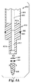
ここで図1Aを参照すると、本開示に基づく検出装置100の一実施形態の構成要素の断面図が示されている。検出装置の構成要素は、ハウジング110とプランジャ150とを含んでいる。ハウジング110は、下側部分114に隣接した上側部分112を含んでいる。上側部分112と下側部分114とは、型成形などの当該技術分野では周知の方法によって、ポリエチレン又はポリプロピレンなどのポリマー材料から別々に形成することができる。各部分は、実質的に液密な結合を与えるように一体に圧入されるような寸法とするか、あるいは当該技術分野において知られる手段(例えば、接着剤、超音波溶接など)によって一体に結合することができる。また、ハウジングは、例えば、中空体を押し出し成形し、通路を型成形し、熱を用いたプロセスによってハウジングの底をシールするなど、当該技術分野において知られるプロセスによって単一のユニットとして形成することもできる。他の実施形態では、狭い通路を有する挿入部材を一体のハウジング内に配置することによって上側及び下側貯留部(それぞれ120及び124)を形成することができる。
Referring now to FIG. 1A, a cross-sectional view of components of one embodiment of a
上側部分112の、下側部分114からみて遠位となる端部には、プランジャ150を受容するような寸法の開口部113が形成されている。上側部分112の反対側の端部には、ハウジング110の下側部分114内に開口する通路116が形成されている。図に示される実施形態では、上側貯留部120の断面積よりも小さい断面積を有する通路116が、上側部分112を形成する壁の内側の延長部として示されている。また、通路116は、上側部分112の壁の内側にハウジング110の下側部分114に隣接して嵌まる挿入要素によって形成されてもよい(図に示されていない)。挿入要素は、ハウジング110の下側部分114に隣接した通路116を形成することができる。図1Aの上側部分112、下側部分114、及び通路116の相対的比率はあくまで例示的なものであって、試料の体積及び/又は器具の制限条件などの異なるパラメータに対応するうえで必要に応じて適合させることができる。
An
プランジャ150は、一端にハンドル152を、他端に複数のシール(第1の下側シール156及び第2の下側シール157)を有するシャフト151を含んでいる。必要に応じて、プランジャ150は1以上の上側シール154及び/又はインデックスマーク153を含んでもよい。ハンドル152、第1の下側シール156、及び第2の下側シール157間の相対的な距離については後述する。図1Aには更に、必要に応じて用いられる検出試薬165及び必要に応じて用いられるヒドロゲル162が示されている。
「検出試薬」とは、本明細書ではその最も広い意味で使用される。検出試薬とは、生物学的検体を検出するために反応中で使用することのできる試薬である。検出反応の非限定的な例としては、結合相手間の相互作用(例えば、抗原−抗体、受容体−リガンド、プローブ−標的分子、及びハイブリダイゼーション結合相互作用など)、及び/又は酵素反応(例えば、蛍光発生反応、色素生成反応、光発生反応、又は重合反応などの酵素媒介反応)が挙げられる。検出試薬は検出反応に関与する(例えば、結合相手、酵素、酵素基質、又は指示薬として)ものでもよく、かつ/又は検出反応を促進する(例えば、緩衝剤、補因子、又は共役反応の成分として)ものでもよい。検出試薬の例としては、例えば、ルシフェラーゼ、アデニル酸キナーゼ、ペルオキシダーゼ、アルカリフォスファターゼ、アピラーゼなどの酵素、例えば、ルシフェリン、リン酸メチルウンベリフェリル、o−ニトロフェニルリン酸、p−ニトロフェニルリン酸、及び5−ブロモ−4−クロロ−3−インドキシル−リン酸塩などの酵素基質、例えば、リン酸緩衝液、TRIS緩衝液、及びHEPES緩衝液などの緩衝液、並びに、FADH、NADH、補酵素Aなどの補因子が挙げられる。 “Detection reagent” is used herein in its broadest sense. A detection reagent is a reagent that can be used in a reaction to detect a biological analyte. Non-limiting examples of detection reactions include interactions between binding partners (eg, antigen-antibody, receptor-ligand, probe-target molecule, and hybridization binding interactions), and / or enzymatic reactions (eg, , An enzyme-mediated reaction such as a fluorescence generation reaction, a dye generation reaction, a light generation reaction, or a polymerization reaction). The detection reagent may be involved in the detection reaction (eg, as a binding partner, enzyme, enzyme substrate, or indicator) and / or facilitate the detection reaction (eg, as a buffer, cofactor, or component of a coupling reaction). ) May be used. Examples of detection reagents include, for example, enzymes such as luciferase, adenylate kinase, peroxidase, alkaline phosphatase, and apyrase, such as luciferin, methylumbelliferyl phosphate, o-nitrophenyl phosphate, p-nitrophenyl phosphate, And enzyme substrates such as 5-bromo-4-chloro-3-indoxyl-phosphate, eg, buffers such as phosphate buffer, TRIS buffer, and HEPES buffer, and FADH, NADH, coenzyme Cofactors such as A can be mentioned.
検出試薬は、様々な形態でハウジング110内に含まれうる。例えば、検出試薬165は、図1Aに示されるような乾燥した又は部分的に乾燥したコーティングからなるものでよい。検出試薬165に適した別の形態(図に示されていない)は当該技術分野では周知のものであり、例えば、液体試薬(必要に応じて、アンプルのような破断可能な区画内に入った)、粉末、ゲル、錠剤、凍結乾燥試薬、コーティングされたフィルム、ケーキ、及び、完全乾燥試薬(dried-down reagent)などが挙げられる。
The detection reagent can be contained within the
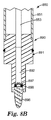
図1Bは、図1Aのプランジャ150を有するハウジング110を含む検出装置100の断面図を示す。この図は、装置100を使用前に保管することができるような形態を示している。プランジャ150は、ハウジング110内に完全に挿入されている。この位置では、ハンドル152の下縁部がハウジング110の上側部分112の開口部113を封鎖することによって、ハウジング110への物質の出入りが防止されている。必要に応じて用いられる上側シール154も、ハウジング110への物質の出入りを防止するうえで機能しうる。上側シール154はハウジング110の上側部分112の壁の内表面と接触するような寸法に構成され、バリア、好ましくは液密バリアを形成するのに適した材料(例えば、ポリプロピレン、ブチルゴムなど)で形成される。
FIG. 1B shows a cross-sectional view of a
プランジャ150が図1Bに示される位置にある場合、第1の下側シール156が通路116を封鎖することにより、ハウジング110の上側貯留部120が下側貯留部124から隔離される。プランジャ150が図1Bに示される位置にある場合、プランジャ150の第2の下側シール157を含む部分が下側貯留部124内に延びており、この部分はハウジング110の下側部分114の壁と接触していない。第1の下側シール156及び第2の下側シール157は通路116の壁と接触するような寸法となっており、上側貯留部120と下側貯留部124との間において通路116内にバリア、好ましくは液密バリアを形成するのに適した材料(例えば、ポリプロピレン、ブチルゴムなど)で形成される。図1Bには更に、上側貯留部120内に配置された、必要に応じて用いられる濃縮剤130が示されている。
When the
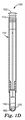
図1Cは、プランジャ150が第2の位置にある図1Bの装置100の断面図を示す。このプランジャ150は、例えばハウジング110内に試料を装填するために使用することができる。プランジャ150は、ハンドル152を把持して、第2の下側シール157が通路116の上端に近くなる位置にまで引き出すことができる。必要に応じて用いられるプランジャシャフト151上のインデックスマーク153を用いて(例えば、インデックスマーク153が開口部113と整列した時点で)、この位置に達するためのプランジャ150の適切な位置を示すことができる。図1Cは更に、上側貯留部120内の濃縮剤130と接触している液体試料140を含んでいる。使用時には、装置100を例えばボルテックスにかける又は振動させることによって濃縮剤130と液体試料140とを混合することができる。所定の時間の後、濃縮剤130は図1Cに示されるように上側貯留部120の底に沈殿しうる。特定の実施形態では、必要に応じて用いられるテーパ領域118が通路116に隣接して配置される。テーパ領域118は、ハウジング110の上側部分112及び/又は通路116と同じ材料及び/又はプロセスによって形成することができる。使用時には、テーパ領域118は、ハウジング110の内部において通路116の方向に沈降する、液体に懸濁された粒子(例えば、細胞濃縮剤130)を通路116の方向に向かわせることができる。
FIG. 1C shows a cross-sectional view of the
図1Dは、図1Bに示される第1の位置にプランジャ150が戻された、図1Cの装置100の断面図を示す。ハンドル152の下縁部は開口部113に近い位置にあり、液体試料の、濃縮剤130を含む部分142が下側貯留部124に移され、そこで部分142は検出試薬165(図1Aに示される)が存在する場合に試薬165と相互作用することができる。部分142と検出試薬165との間の相互作用の非限定的な例としては、検出試薬の溶解及び/又は懸濁、検出試薬と部分中に存在する生物学的検体との間の結合相互作用、及び/又は酵素反応が挙げられる。図1Dは更に、液体試料の部分142が下側貯留部124内のヒドロゲル162と接触している状態を示しており、これによりヒドロゲル162から細胞抽出剤が放出されうる。
FIG. 1D shows a cross-sectional view of the
図1に示される実施形態では、下側貯留部124から上側貯留部120を隔離するための手段は、プランジャ150の第1の下側シール156及び/又は第2の下側シール157と通路116との組み合わせからなっている。図1に示される実施形態では、濃縮剤130を上側貯留部120から下側貯留部124に移動するための手段は、通路116、並びにプランジャ150の第1の下側シール156及び第2の下側シール157を含んでいる。
In the embodiment shown in FIG. 1, the means for isolating the
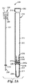
図2Aは、本発明に基づく検出装置200の一実施形態の構成要素であるプランジャ250の断面図、及びハウジング210の部分分解断面図である。ハウジング210は、下側部分214に隣接した上側部分212を含んでいる。上側部分212及び下側部分214は上記に述べたように形成することができる。
FIG. 2A is a cross-sectional view of a
上側部分212の、下側部分214からみて遠位となる端部には、プランジャ250を受容するような寸法の開口部213が形成されている。上側部分212の反対側の端部には、上記に述べたような通路216が形成されている。必要に応じて用いられる上記に述べたようなテーパ領域218が、通路216に隣接して形成されている。破断可能なシール260a及び260bによって、ハウジングが上側貯留部220、下側貯留部224、及び第3の貯留部226に分割されている。破断可能なシール260a及び260bは耐水性材料(例えば、薄いポリマーフィルム、ポリマーコーティングされた紙、薄い箔など)で形成されることが好ましく、当該技術分野では周知の材料及び/又はプロセス(例えば、接着剤、熱シール、超音波接着)を用いて耐水性の破断可能なバリアを形成するようにハウジング210の壁に固定することができる。
An
第3の貯留部226内には、細胞抽出剤を含むハイドロゲル262が配置されている。細胞抽出剤を含む好適なヒドロゲルについては、本明細書にその全容を援用する、発明の名称が「生体検出用物品」(BIODETECTION ARTICLES)である、2008年9月30日出願の米国特許出願第61/101,546号に述べられている。
In the
図2Aの3個の貯留部の相対的比率はあくまで例示的なものであって、試料の体積及び/又は器具の制限条件などの異なるパラメータに対応するうえで必要に応じて適合させることができる。図2Aには更に、必要に応じて用いられる濃縮剤230、本明細書で述べるような必要に応じて用いられる検出試薬265、及び必要に応じて用いられる着脱式キャップ278が示されている。キャップ278は、当該技術分野では周知のプロセス(例えば、型成形)を用いてポリマー材料(例えば、ポリエチレン、ポリプロピレンなど)から形成することができ、ハウジング210の液密カバーを形成するような寸法とすることができる。
The relative proportions of the three reservoirs in FIG. 2A are exemplary only and can be adapted as needed to accommodate different parameters such as sample volume and / or instrument limitations. . FIG. 2A further shows a concentrating
プランジャ250は、一方の端部にハンドル252を、反対側の端部に下側シール256及び穿孔端259を有するシャフト251を含んでいる。好ましくは、下側シール256は通路216の壁と接触するような寸法となっており、通路216内にバリア、好ましくは液密バリアを形成するのに適した材料(例えば、ポリプロピレン、ブチルゴムなど)で形成される。必要に応じて、プランジャ250は上記に述べたような1以上の上側シール254を含んでよい。ハンドル252、下側シール256、及び穿孔端259間の相対距離については後述する。
図2Bは、図2Aの装置200の断面図を示す。この図では、ハウジング210は上側貯留部220内に液体試料240を更に含んでいる。キャップ278はハウジング210上にしっかりと着座しているため、ハウジング210をボルテックス、振動、振盪、又は反転するなど、当該技術分野では周知のプロセスによって液体試料240を細胞濃縮剤230と混合することができる。混合の後、細胞濃縮剤230を通路216内の破断可能なシール260a上に沈殿させることができる。
FIG. 2B shows a cross-sectional view of the
図2Cは、プランジャ250が部分的に挿入された図2Bのハウジング210を含む装置200の断面図を示す。この位置では、プランジャ250の下側シール256が通路216の壁と接触することにより、通路216内において少なくとも部分242を液体試料240の残りの部分から隔離している。通路216内には細胞濃縮剤230が更に隔離されている。
FIG. 2C shows a cross-sectional view of the
図2Dは、プランジャ250が完全に挿入された図2Cの装置200の断面図を示す。プランジャ250の下側シール256が通路216の壁に接触し、穿孔端259が破断可能なシール260a及び260bに穿孔していることにより、液体試料の部分242、細胞濃縮剤230、及びヒドロゲル262が下側貯留部224内に移され、そこで必要に応じて用いられる検出試薬265(図2Aに示される)が存在する場合に部分242が検出試薬265と相互作用することができる。部分242と検出試薬265との間の相互作用の非限定的な例としては、検出試薬の溶解及び/又は懸濁、検出試薬と部分中に存在する生物学的検体との間の結合相互作用、及び/又は酵素反応が挙げられる。
FIG. 2D shows a cross-sectional view of the
図2に示される実施形態では、下側貯留部224から上側貯留部220を隔離するための手段には、破断可能なシート260a及び260bが含まれる。下側貯留部224から上側貯留部220を隔離するための手段には、プランジャ250の下側シール256と通路216との組み合わせが更に含まれる。図2に示される実施形態では、上側貯留部220から下側貯留部224に細胞濃縮剤230を移動させるための手段には、プランジャ250の穿孔端259及び下側シール256、並びに通路216が含まれる。
In the embodiment shown in FIG. 2, means for isolating the
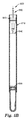
図3Aは、本開示に基づく検出装置300の一実施形態の正面図を示す。装置300は、ハウジング310及び必要に応じて用いられるキャップ378を含んでいる。ハウジング310は、上記に述べたように上側部分312、通路316、及び下側部分314を有するように構成することができる。必要に応じて用いられるキャップ378は、上記に述べたように構成することができる。装置300は、図3Aの第1の位置に示される弁アクチュエータ372を有する行き止まり弁370を更に含んでいる。図3Bは、図3Aの装置300及び弁アクチュエータ372の側面図である。
FIG. 3A shows a front view of an embodiment of a
図3Cは、図3Aに示される装置300の断面図を示す。装置300は、キャップ378及びハウジング310を含んでいる。ハウジング310は、上側部分312及び下側部分314を含んでいる。上側部分312は、内部に行き止まり弁370が配置された通路316を含んでいる。行き止まり弁370は、弁がこの第1の位置にある場合に上側貯留部320と流体連通する弁キャビティ374を含んでいる。弁キャビティ374は、上側貯留部320内の液体試料340と接触する、必要に応じて用いられる細胞濃縮剤330を含んでいる。下側貯留部324には、いずれも本明細書で述べるような、必要に応じて用いられるヒドロゲル362及び/又は必要に応じて用いられる検出試薬365が入っている。図3Cには更に、本明細書で述べるような必要に応じて用いられるテーパ領域318が示されている。
FIG. 3C shows a cross-sectional view of the
図3Dは、弁370が第2の位置にある図3Cの装置300の断面図が示されている。弁370が第2の位置にある場合、液体試料の、細胞濃縮剤330を含む部分342は隔離されて下側貯留部324に移され、そこで部分342は、本明細書で述べるようなヒドロゲル362が存在する場合にはヒドロゲル362と接触し、検出試薬365が存在する場合には検出試薬365と相互作用することができる。
FIG. 3D shows a cross-sectional view of the
弁キャビティ374の寸法が既知の所定用量を与え、そのため弁370を1回以上使用して所定量の液体試料340を上側貯留部320から下側貯留部324に移すことが可能である点は認識される。更に、液体試料の部分342が上側貯留部320から下側貯留部324に移された後、上側貯留部320内の液体試料340の残部を捨て、異なる物質(例えば、希釈剤、緩衝剤、液体及び/又は粉末試薬)を上側貯留部320内に入れ、その後弁370を使用して所定量を下側貯留部324に移すことが可能である点も認識される(図には示されていない)。
It is recognized that the size of the
図3に示される実施形態では、ハウジングの上側貯留部320と下側貯留部324とを隔離するための手段には弁370が含まれる。図3に示される実施形態では、上側貯留部320から下側貯留部324に細胞濃縮剤330を移動するための手段には、通路316及び弁370が含まれる。
In the embodiment shown in FIG. 3, the means for isolating the
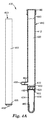
図4Aは、いずれも本開示に基づく検出装置400の構成要素である、プランジャ450の側面図及びハウジング410の断面図を示す。プランジャは、シャフト451、必要に応じて用いられるOリング455、及び穿孔端459を含んでいる。Oリングは、ハウジング410との液密なシールを与えるように柔軟性のある材料(例えば、ブチルゴム)で形成することができる。ハウジング410は、上記に述べたように上側部分412及び下側部分414を有するように構成することができる。必要に応じて用いられるキャップ478は、上記に述べたように構成することができる。破断可能なシール460が、ハウジング410を3個の貯留部(上側貯留部420、下側貯留部424、及び第3の貯留部426)に分割している。この図では、破断可能なシール460は上側貯留部420の下側貯留部424に近い方の端部に配置されている。破断可能なシール460間の空間によって第3の貯留部426が画定されている。第3の貯留部426内には、細胞抽出剤を含むハイドロゲル462が配置されている。別の構成(図に示されていない)では、下側貯留部424の近くに1個のみの破断可能なシール460を有し、図3Cに示されるようにヒドロゲル462が下側貯留部424内に配置されていてもよい。
FIG. 4A shows a side view of the
上側貯留部420内の破断可能なシール460の近くには、閉位置で示されている弁ゲート482を有するドレーン弁480が配置されている。上側貯留部420内には、液体試料440及び必要に応じて用いられる細胞濃縮剤430が更に配置されている。必要に応じて用いられる検出試薬465が下側貯留部424内に示されている。
Located near the
図4Bは、図4Aのハウジング410及びプランジャ450を含む組み立てられた状態の検出装置400の断面図を示す。細胞濃縮剤430は上側貯留部420の底に沈殿している。ドレーン弁480の弁ゲート482は開位置にあり、矢印によって示される方向に力が作用する(例えば、指又は手からの圧力によって)と、清澄化した液体試料445がドレーン弁480から排出される。図4Bには更に、下側貯留部424の壁にコーティングされた検出試薬465が示されている。
FIG. 4B shows a cross-sectional view of the assembled
図4Cは、図4Bの検出装置400の断面図を示す。この図では、プランジャ450のOリング455及び穿孔端459が、ドレーン弁480の、最も近くの破断可能なシール460に近い方の側でハウジング410内に挿入されている。この位置では、プランジャ450によって、液体試料の細胞濃縮剤430を含む部分442がプランジャ450と最も近くの破断可能なシール460との間に閉じ込められる。
FIG. 4C shows a cross-sectional view of the
図4Dは、図4Cの検出装置400の断面図を示す。この図では、プランジャ450の穿孔端459が破断可能なシール460の両方を貫通しており、液体試料の部分442が下側貯留部424へと移動しており、下側貯留部424において部分442が検出試薬(図4Cに示される)を溶解し、細胞抽出剤を含むヒドロゲル462と接触している。
FIG. 4D shows a cross-sectional view of the
図5Aは、いずれも検出装置500の構成要素であるプランジャ550及びハウジング510の断面図を示す。プランジャ550は、必要に応じて用いられるハンドル552及び先端部590を備えるシャフト551を含んでいる。任意の実施形態において、ハンドル552は必要に応じて用いられるOリング555を更に含んでもよい。
FIG. 5A shows a cross-sectional view of the
ハウジング510は、上記に述べたように上側部分512及び下側部分514を有するように構成することができる。破断可能なシール560a及び560bが、ハウジング510を3個の貯留部(上側貯留部520、下側貯留部524、及び第3の貯留部526)に分割している。この図では、破断可能なシール560a及び560bは上側貯留部520の、下側貯留部524に近い方の端部に配置されている。破断可能なシール560aと560bとの間の空間によって、第3の貯留部526が画定されている。第3の貯留部526内には、本明細書で述べるような細胞抽出剤を含むヒドロゲル562が配置されている。図に示される実施形態では、下側貯留部524は必要に応じて用いられる検出試薬565を含んでいる。別の構成(図に示されていない)では、下側貯留部の近くに1個のみの破断可能なシールを有し、図3Cに示されるようにヒドロゲルが下側貯留部内に配置されてもよい。
The
ハンドル552は、例えば、プラスチック、木材、金属、及びこれらの組み合わせなどの各種の材料から、当該技術分野では周知のプロセスを用いて作製することができる。必要に応じて用いられるOリング555は、ハンドル552の切り欠き554内に配置されている。ハンドル552は、プランジャ550がハウジング510に完全に挿入される際に、ハンドル552の少なくとも一部がハウジング510に挿入されうるような形状及び寸法とすることができる。一実施形態では、ハンドル552は、ハウジング510の開口部と係合して、ハンドル552がハウジング510に完全に挿入されることを防止するリム554を更に含む。
The
プランジャ550のシャフト551は、例えば、プラスチック、木材、金属、及びこれらの組み合わせなどの各種の材料で形成することができる。シャフト551の一端は、例えば、凹部(図5に示される)に圧入することにより、超音波溶接により、又は接着剤を使用することによりハンドル552に対して結合される。シャフト551の他端は、例えば、圧入により、超音波溶接により、又は接着剤を使用することにより先端部590に対して結合される。
The
プランジャ550の先端部590の細部が図6A及び6Bに示されている。
Details of the
図6Aは、部分的に断面にて示された図5Aの先端部590の部分分解側面図を示す。先端部690は、本体691、一方向弁697、及びフィルター696を含んでいる。
6A shows a partially exploded side view of the
本体691は、第1の端部691a、第2の端部691b、及び第1の端部691aから第2の端部691bへと本体691を通じて延びる導管692を含んでいる。第1の端部691aにおいて、導管692はプランジャのシャフト651によってシールされている。第2の端部691bにおいて、導管692は陥凹した開口部694内に開口する。2本のドレーン通路695が、本体691の第1の端部691aから導管692へと延びている。したがって、各ドレーン通路は導管692及び陥凹開口部694に流体接続されている。一実施形態(図に示されていない)では、先端部690は1本のみのドレーン通路695を含んでもよい。複数のドレーン通路695によれば背圧が低くなりうるために、先端部690を通じた流体の輸送速度が大きくなり有利である。
The
本体691は、例えば、型成形することなどによりプラスチック(例えば、ポリプロピレン、ポリエチレン、ポリテトラフルオロエチレンなど)から作製することができる。本体691は、ハウジング(例えば、図5Aのハウジング510)内に嵌合するような形状及び寸法に構成される。任意の実施形態において、本体691又はOリング686は、本体691がハウジングに挿入される際に、ハウジングの壁と実質的に液密なシールを形成することができる。Oリング686を含む任意の実施形態では、Oリング686は液密なシールを形成することと、Oリング686がハウジングの壁に対して動かされる際に、ハウジングの壁から粒子状物質(例えば、細胞濃縮剤)を拭い取ることとの両方の機能を有しうる。シャフト651は、当該技術分野では周知の手段によって(例えば、接着剤、圧入などにより)導管692と連結することができる。必要に応じて用いられるOリング686は、本体691の切り欠き689内に配置される。
The
先端部690はフィルター696を更に含んでいる。フィルター696は、本体691に対して結合されている。図に示される実施形態では、フィルター696は、陥凹開口部694に圧入及び/又は接着剤により結合することが可能な多孔質材料で形成されている。特定の実施形態では、多孔質材料は半剛性の多孔質材料(例えば、ポレックス社(Porex Corporation)(ジョージア州フェアバーン)により部品番号X6854として販売されるPOREX濾過媒質)であってよい。フィルター696は、比較的角張った、あるいは尖った端部を有するように構成することにより、端部が破断可能なシールを容易に貫通することができる。代替的な実施形態(図に示されていない)では、フィルターは、本体に対して結合された膜フィルターからなるものでよい。膜フィルターは本体と結合されると、導管及びドレーン通路を含む流体経路の一部を形成する。
The
特定の実施形態では、フィルター696の多孔度は、フィルター696が比較的大きな粒子(例えば、>1μm、>5μm、又は>10μm)の通過のみを防止するように選択することができる。比較的大きな粒子には、例えば、本明細書で述べるような細胞濃縮剤が含まれる。これらの実施形態では、細菌、酵母、及び/又は真菌類(カビ)の糸状体などの微生物はフィルター696を通過することができる。
In certain embodiments, the porosity of the
特定の実施形態では、フィルター696の多孔度は、フィルター696が比較的小さな粒子(例えば、<1μm、<0.45μm、又は<0.2μm)の通過のみを防止するように選択することができる。これらの実施形態では、細菌、酵母、及び/又は真菌類(カビ)の糸状体などの微生物はフィルター696によって保持されうる。
In certain embodiments, the porosity of the
先端部690は、陥凹開口部694内においてフィルター696と導管692との間に配置される一方向弁697を更に含む。必要に応じて用いられる、一方向弁697を定位置に保持する機能を有する保持ワッシャ698も更に示されている。一方向弁697はプラスチック(例えば、ポリプロピレン、ポリエチレン、ポリエステルなど)又はゴムで形成することができ、例えば、ダックビル弁として構成することができる。使用時には、一方向弁697は、フィルター696を通過した液体の流れがフィルター696を通じて逆方向に戻ることを実質的に防止する。
The
図6Bは、組み立てられた状態の図6Aの先端部690の、部分的に断面にて示された側面図を示す。一方向弁697、必要に応じて用いられる保持ワッシャ698、及びフィルター696が陥凹した開口部内に配置され、導管692及びドレーン通路695と流体接続している。シャフト651は、先端部690の本体691に対して結合されている。
6B shows a side view, partially shown in section, of the
図5Aを再び参照すると、ハウジング510及びプランジャ550を含む検出装置500は、微生物、特に生きた微生物を検出するための方法において使用される。
Referring again to FIG. 5A, a
使用時には、液体試料はハウジング510の上側貯留部520内に移され、そこで細胞濃縮剤530と接触させられる。液体試料540がハウジング510に加えられた後、プランジャ550の先端部がハウジング510に挿入され、図5Bに示されるようにハウジング510の下側貯留部524の方向に押される(例えば、手動により、又は機械的に)。プランジャ550の先端部591が液体試料540と接触すると、図5Bに示されるように液体は先端部590を通過してハウジング510内に戻る。このプロセスでは、細胞濃縮剤530、及び特定の実施形態では遊離微生物が、液体試料の第3の貯留部526に近い部分542内に保持される。
In use, the liquid sample is transferred into the
プランジャ550の先端部590が図に示されていない破断可能なシール560aを貫通すると、液体試料の細胞濃縮剤530を含む部分542がヒドロゲル562と接触する。プランジャ550が更に動く(図5Dに示されるように)と破断可能なシール560bを貫通し、これにより液体試料の部分542及びヒドロゲル562が下側貯留部524に移動し、そこで検出試薬565と接触する。
As the
図7Aは、本開示に基づく検出装置700の別の実施形態の側断面図を示す。検出装置700はプランジャ750及びハウジング610を含んでいる。
FIG. 7A shows a side cross-sectional view of another embodiment of a
ハウジング710は、上記に述べたようにして上側部分712及び下側部分714を有するように構成することができる。破断可能なシール760a及び760bが、ハウジング710を3個の貯留部(上側貯留部720、下側貯留部724、及び第3の貯留部726)に分割している。この図では、破断可能なシール760a及び760bは、上側貯留部720の下側貯留部724に近い方の端部に配置されている。破断可能なシール760aと760bとの間の空間によって第3の貯留部726が画定されている。第3の貯留部726内には、細胞抽出剤を含むヒドロゲル762が配置されている。図に示される実施形態では、下側貯留部724は必要に応じて用いられる検出試薬765を含んでいる。別の構成(図に示されていない)では、下側貯留部724の近くに1個のみの破断可能なシール760を有し、図3Cに示されるようにヒドロゲル762が下側貯留部724内に配置されてもよい。
The
プランジャ750は、ハンドル752及び先端部790に連結されたシャフト751を含んでいる。この実施形態では、シャフト751は中空であり、ハンドルはシャフト751の内部と外部との間で圧力を等しくするための通気口748を含んでいる。プランジャは、必要に応じて用いられるドレーン管753を更に含んでいる。ドレーン管753は先端部790から液体濾液を受けて、この濾液をシャフト751の内部に分配する。ドレーン管753は更に、オーバーフロー弁として機能することによって逆方向に先端部790を通じて逆流する濾液の量を低減させる。
プランジャ750の先端部790の細部が図8に示されている。
Details of the
図8Aは、部分的に断面にて示された図7Aの先端部790の部分分解側面図を示す。先端部890は、本体891、必要に応じて用いられる一方向弁897、及びフィルター896を含んでいる。図8Aには更には、プランジャ850の、中空シャフト851及びドレーン管853を含む部分も示されている。
FIG. 8A shows a partially exploded side view of the
本体891は、第1の端部891a、第2の端部891b、及び第1の端部891aから第2の端部891bへと本体891を通じて延びる導管892を含んでいる。第1の端部891aにおいて、導管892はプランジャのドレーン管853と連結されている(例えば、圧入、及び接着剤、又はネジによる連結により)。第2の端部891bにおいて、導管892は陥凹した開口部894内に開口している。したがって、陥凹開口部894は導管892及びドレーン管853と流体連結されている。
The
本体891は、例えば、型成形することなどによりプラスチック(例えば、ポリプロピレン、ポリエチレン、ポリテトラフルオロエチレンなど)から作製することができる。本体891は、ハウジング(例えば、図7Aのハウジング710)内に嵌合するような形状及び寸法に構成される。任意の実施形態において、本体891又はOリング886は、本体891がハウジングに挿入される際に、ハウジングの壁と実質的に液密なシールを形成することができる。Oリング886を含む任意の実施形態では、Oリング886は液密なシールを形成することと、Oリング886がハウジングの壁に対して動かされる際に、ハウジングの壁から粒子状物質(例えば、細胞濃縮剤)を拭い取ることとの両方の機能を有しうる。シャフト851は、当該技術分野では周知の手段によって(例えば、接着剤、圧入などにより)導管892と連結することができる。必要に応じて用いられるOリング886は、本体891の切り欠き889内に配置される。
The
先端部890はフィルター896を更に含んでいる。フィルター896は、陥凹開口部894において本体891に対して結合されている。図に示される実施形態では、フィルター896は、陥凹開口部894に圧入及び/又は接着剤により結合することが可能な多孔質材料で形成されている。特定の実施形態では、多孔質材料は半剛性の多孔質材料(例えば、ポレックス社(Porex Corporation)(ジョージア州フェアバーン)により部品番号X6854として販売されるPOREX濾過媒質)であってよい。フィルター896は、比較的角張った、あるいは尖った端部を有するように構成することにより、端部が破断可能なシールを容易に貫通することができる。代替的な実施形態(図に示されていない)では、フィルターは、本体に対して結合された膜フィルターからなるものでよい。膜フィルターは本体と結合されると、導管及びドレーン通路を含む流体経路の一部を形成する。
The
特定の実施形態では、フィルター896の多孔度は、フィルター896が比較的大きな粒子(例えば、>1μm,>5μm、又は>10μm)の通過のみを防止するように選択することができる。比較的大きな粒子には、例えば、本明細書で述べるような細胞濃縮剤が含まれる。これらの実施形態では、細菌、酵母、及び/又は真菌類(カビ)の糸状体などの微生物はフィルター896を通過することができる。
In certain embodiments, the porosity of the
特定の実施形態では、フィルター896の多孔度は、フィルター896が比較的小さな粒子(例えば、<1μm、<0.45μm、又は<0.2μm)の通過のみを防止するように選択することができる。これらの実施形態では、細菌、酵母、及び/又は真菌類(カビ)の糸状体などの微生物はフィルター896によって保持されうる。
In certain embodiments, the porosity of
先端部890は、陥凹開口部894内においてフィルター896と導管892との間に配置される、必要に応じて用いられる一方向弁897を更に含みうる。必要に応じて用いられる、一方向弁897を定位置に保持する機能を有する保持ワッシャ898も示されている。一方向弁897は、プラスチック(例えば、ポリプロピレン、ポリエチレン、ポリエステルなど)又はゴムで形成することができ、例えば、ダックビル弁として構成することができる。使用時には、一方向弁897は、フィルター896を通過した液体の流れがフィルター896を通じて逆方向に戻ることを実質的に防止する。
The
図8Bは、組み立てられた状態の図7Aの先端部790の、部分的に断面にて示された側面図を示す。一方向弁897、必要に応じて用いられる保持ワッシャ898、及びフィルター896が陥凹した開口部内に配置され、導管892及びドレーン管853と流体接続している。シャフト851は、先端部890の本体891に対して結合されている。
FIG. 8B shows a side view, partially shown in section, of the
図7Aを再び参照すると、ハウジング710及びプランジャ750を含む検出装置700は、微生物、特に生きた微生物を検出するための方法において使用される。
Referring again to FIG. 7A, a
使用時には、液体試料はハウジング710の上側貯留部720内に移され、そこで細胞濃縮剤730と接触させられる。液体試料740がハウジング710に加えられた後、プランジャ750の先端部790がハウジング710に挿入され、図7Bに示されるようにハウジング710の下側貯留部724の方向に押される(例えば、手動により、又は機械的に)。プランジャ750の先端部791が液体試料740と接触すると、図7Bに示されるように液体は先端部790を通過して、ドレーン管753を通過して、プランジャ750の中空シャフト内に戻る。このプロセスでは、細胞濃縮剤730、及び特定の実施形態では、遊離微生物が、液体試料の第3の貯留部726に近い部分742内に保持される。
In use, the liquid sample is transferred into the upper reservoir 720 of the
プランジャ750の先端部790が図に示されていない破断可能なシール760aを貫通すると、液体試料の細胞濃縮剤730を含む部分742がヒドロゲル762と接触する。プランジャ750が更に動く(図7Dに示されるように)と破断可能なシール760bを貫通し、これにより液体試料の部分742及びヒドロゲル762が下側貯留部724に移動し、そこで検出試薬765と接触する。
As the
本開示の装置は、ハウジング内に破断可能なシールを含んでいる。破断可能なシールが穿孔されることによって、装置の1つの区画から別の区画へと細胞濃縮剤が輸送される。特定の実施形態では、このプロセスで移動させられる細胞濃縮剤の量を、破断可能なシールの比較的面積に細胞濃縮剤を集めることによって大きくすることができる。図9は、細胞濃縮剤の回収率を高めるための回収要素967の一実施形態を示す。回収要素967は、本開示に基づく検出装置のハウジング内に嵌合するような寸法に構成されている。回収要素967は、細胞濃縮剤(図に示されていない)を含む試料の方向に向けられる面取りされた縁部968を含んでいる。通常、面取りされた縁部968は、重力によって沈降する粒子を回収するように上側を向いている。また、面取りされた縁部968を、例えば遠心力又は流体力の方向に向けることによって、重力以外の力が作用する粒子を回収することもできる。回収要素967は、必要に応じて用いられる破断可能なシール969を更に含む。
The apparatus of the present disclosure includes a breakable seal within the housing. A puncturable seal is pierced to transport the cell concentrate from one compartment of the device to another. In certain embodiments, the amount of cell concentrate that is transferred in this process can be increased by collecting the cell concentrate in a relatively area of the breakable seal. FIG. 9 illustrates one embodiment of a
回収要素967は、例えば、ポリマー(例えば、ポリエステル、ポリプロピレン、ポリテトラフルオロエチレン、ポリプロピレン、ポリスチレン、ナイロン、並びにこれらの組み合わせ及び誘導体)、ガラス、及び金属などの各種の材料で形成することができる。回収要素967は、その表面に対する粒子の接着を阻止するための潤滑性コーティングを更に含んでもよい。面取りされた縁部968は、その斜面に沿った粒子の運動を促進するために角度(例えば、45°の角度、45°よりも大きな角度)が付けられていてもよい。破断可能なシール969は本明細書に述べられるようにして作製し、本明細書に述べられるような手段によって回収要素967に結合することができる。
The
図10Aは、回収要素1067を含む検出装置1000の一実施形態を示す。装置1000は、ハウジング1010及びプランジャ1050を含んでいる。ハウジング1010は、上側部分1012及び下側部分1014を含んでいる。上側部分1012の内部かつ下側部分1014の近くに、破断可能なシール1069が結合された回収要素1067が配置されている。破断可能なシール1069は、回収要素1067の下側部分1014に面した側面に結合されている。したがって破断可能なシール1069は、ハウジング1010を上側貯留部1020及び下側貯留部1024の2個の隔離された貯留部に分割する。
FIG. 10A shows one embodiment of a
プランジャ1050は、ハンドル1052、シャフト1051、及び先端部1090を含む。ハンドル1052は上記に述べたように形成することができ、プランジャ1050がハンドル1010内に過度に深く挿入されることを防止するための、ハウジング1010と係合する、必要に応じて用いられるリム1054を含んでよい。ハンドル1052は、ネジ嵌め又は他の連結手段(例えば、圧入、接着剤)によってシャフト1051に対して連結することができる。先端部1090は、本明細書で述べる他の先端部の実施形態について述べられるプロセス及び材料を用いて作製することができる。先端部1090は1以上のガイド1083を含んでもよい。各ガイドはハウジング1010の内部にゆるく嵌まるような寸法に構成され、先端部1090がハウジング1010を通じて長手方向に動く際に、先端部1090の横方向の運動を低減させる機能を有する。
先端部1090は、先端部1090上の固定位置に保持されたスクレーパー1086を更に含んでいる。図の実施形態では、スクレーパー1086は保持部材1087によって固定位置に保持されている。保持部材1087は先端部1090の一部として成形又は機械加工するか、あるいは先端部1090に結合されたブラケット又は複数のブラケットからなるものでよい。また、スクレーパー1086を先端部1090に直接結合する(例えば、接着剤により結合する)こともできる。
The
スクレーパー1086はディスク形状をしており、ハウジング1010の内部に比較的緊密な嵌合を形成するような寸法となっている。特定の実施形態では、スクレーパーはOリングを含みうる。スクレーパー1086は、水性の液体に浸漬される際に、その形状をほぼ維持する必要がある。スクレーパーはハウジングの内部に比較的緊密な嵌合を形成するような寸法でなければならないが、スクレーパーは、プランジャがハウジング1010内の液体試料を通じて押されるに従って液体がその縁部を回り込んで流れることができるように比較的可撓性のものでなければならない。スクレーパー1086を作製するのに適した材料としては、例えば、ポリウレタンゴムが挙げられる。
The
使用時には、図10Bに示されるように液体試料1040と細胞濃縮剤1030とは、装置のハウジング1010内で接触させられる。プランジャ1050がハウジング1010内に挿入され、プランジャ1050の先端部1090がハウジング1010の底の方向に押される。先端部1090が液体試料1040を通過するに従って、スクレーパー1086によって細胞濃縮剤1030がハウジング1010の底の方向に押されるのと同時に、液体試料1040がスクレーパー1086の縁部を回り込んで流れる。有利な点として、この装置によって使用者は、細胞濃縮剤1030が重力によってハウジング1010の底へと沈降させられる場合に、可能であるよりも大幅に短い時間で細胞濃縮剤1030を回収かつ濃縮することができる。更に、可撓性のスクレーパーによって、スクレーパーがなければハウジングの壁に接着しうる細胞濃縮剤1030の部分の回収が容易となる。したがって、本発明の装置1000は細胞濃縮剤の回収率を高め、これにより微生物を濃縮するために細胞濃縮剤を使用する方法の感度を高めるものである。
In use, as shown in FIG. 10B, the
細胞濃縮剤が強磁性材料(例えば、粒子)を含む試料調製及び検出装置では、磁石又は電磁石を装置の近傍に配置することによって粒子(及び粒子に結合した微生物)を、粒子を回収し、かつ/又は粒子を別の貯留部に移すための所望の位置に引き寄せることができる点は認識されるはずである。特定の実施形態では、細胞濃縮剤が液体試料中の微生物のほぼすべてを結合するだけの充分な時間の後に、磁石を装置の近傍(例えば、装置の底の近傍)に配置することができる。 In sample preparation and detection devices where the cell concentrating agent includes a ferromagnetic material (eg, particles), particles (and microorganisms bound to the particles) are recovered by placing a magnet or electromagnet in the vicinity of the device, and It should be appreciated that the particles can be attracted to the desired location for transfer to another reservoir. In certain embodiments, the magnet can be placed in the vicinity of the device (eg, near the bottom of the device) after sufficient time for the cell concentrating agent to bind substantially all of the microorganisms in the liquid sample.
生きた細胞からの生物学的検体の検出方法:
本開示の方法には、有効量の細胞抽出剤への曝露後に、例えば生きた微生物などの、生きた細胞から放出される生物学的検体を検出するための方法が含まれる。
Methods for detecting biological specimens from living cells:
The methods of the present disclosure include methods for detecting biological analytes released from living cells, such as living microorganisms, after exposure to an effective amount of cell extractant.
本開示の方法には、生きた細胞を含むことが疑われる試料、及び細胞抽出剤を含むヒドロゲルを含む液体混合物を形成することが含まれる。本開示の方法は、生物学的検体を検出する工程を更に含む。生物学的検体を検出する工程は、試料中の生物学的検体の量を定量することを更に含みうる。 The methods of the present disclosure include forming a liquid mixture comprising a sample suspected of containing living cells and a hydrogel containing a cell extractant. The disclosed method further comprises detecting a biological analyte. The step of detecting the biological analyte can further include quantifying the amount of the biological analyte in the sample.
一態様では、本開示は試料中の細胞を検出する方法を提供する。本方法は、細胞濃縮剤、細胞抽出剤を含むヒドロゲル、及び細胞を含むことが疑われる液体試料を提供する工程を含む。好適な細胞濃縮剤が、本明細書にその全容を援用する、2007年10月3日出願の発明の名称が「微生物の濃縮プロセス」(MICROORGANISM CONCENTRATION PROCESS)である米国特許出願第60/977,180号に述べられている。 In one aspect, the present disclosure provides a method of detecting cells in a sample. The method includes providing a cell concentrate, a hydrogel comprising a cell extractant, and a liquid sample suspected of containing cells. A suitable cell concentrating agent is US patent application Ser. No. 60/977, whose title is “MICROORGANISM CONCENTRATION PROCESS”, filed Oct. 3, 2007, which is incorporated herein in its entirety. No. 180.
本方法は、液体試料を細胞濃縮剤と所定の時間にわたって接触させる工程を更に含む。細胞濃縮剤は、粒子、繊維、粒子を含むマトリクス(例えば、繊維状マトリクス)、又は上記の2以上のものの任意の組み合わせを含みうる。細胞濃縮剤は、接触時間の間に液体試料に懸濁することができる。懸濁液は試験管、試験管、フラスコ、ビーカー又は本明細書で述べる検出装置のいずれかのような容器に入れることができる。特定の好ましい実施形態では、液体試料は、例えば、懸濁液を攪拌、ボルテックス、又は振動することによって、所定の時間にわたって細胞濃縮剤と混合される。細胞濃縮剤が液体試料と接触させられている間に、液体試料からの細胞が細胞濃縮剤と結合する。 The method further includes contacting the liquid sample with the cell concentrate for a predetermined time. The cell concentrating agent can include particles, fibers, a matrix containing particles (eg, a fibrous matrix), or any combination of two or more of the above. The cell concentrate can be suspended in the liquid sample during the contact time. The suspension can be placed in a container such as a test tube, test tube, flask, beaker or any of the detection devices described herein. In certain preferred embodiments, the liquid sample is mixed with the cell concentrate for a predetermined period of time, for example, by stirring, vortexing, or shaking the suspension. While the cell concentrate is in contact with the liquid sample, cells from the liquid sample bind to the cell concentrate.
本方法は、液体試料の少なくとも一部から細胞濃縮剤を分離する工程を更に含む。このプロセスにおいて、細胞濃縮剤を最初の液体試料よりも小さな体積に濃縮することができる。細胞濃縮剤は、様々な手段によって液体試料の少なくとも一部から分離することができる。例えば、細胞濃縮剤が液体試料よりも大きな比重を有する場合、細胞濃縮剤は懸濁液の底に沈降しうる。液体試料の少なくとも一部を除去する(例えば、ピペッティング又はデカンテーションにより)ことができる。これに代えるか又はこれに加えて、液体試料の少なくとも一部を遠心分離又は濾過によって除去することもできる。 The method further includes separating the cell concentrate from at least a portion of the liquid sample. In this process, the cell concentrating agent can be concentrated to a smaller volume than the initial liquid sample. The cell concentrating agent can be separated from at least a portion of the liquid sample by various means. For example, if the cell concentrate has a greater specific gravity than the liquid sample, the cell concentrate can settle to the bottom of the suspension. At least a portion of the liquid sample can be removed (eg, by pipetting or decanting). Alternatively or in addition, at least a portion of the liquid sample can be removed by centrifugation or filtration.
フィルターはその孔径によって(例えば、その泡立ち点の孔径によって)定義することができる。フィルターの泡立ち点の孔径は、一般的にフィルターの孔の最大径の平均である。特定の実施形態では、フィルターは細胞濃縮剤の平均径よりも小さい平均孔径を有しうる。これらの比較的大きな孔径を有するフィルターを利用することができるために、本明細書で開示される方法は、水試料などの試料から微生物を分離するための他の方法と比較した場合に大きな利点を有する。 A filter can be defined by its pore size (eg, by the pore size of its bubble point). The pore size at the bubble point of the filter is generally the average of the maximum pore size of the filter. In certain embodiments, the filter may have an average pore size that is smaller than the average size of the cell concentrating agent. Because of the ability to utilize filters with these relatively large pore sizes, the methods disclosed herein have significant advantages when compared to other methods for separating microorganisms from samples such as water samples. Have
一実施形態では、フィルターは少なくとも約1マイクロメートル(μm)以上の平均孔径を有しうる。一実施形態では、フィルターは少なくとも約1.5μm以上の平均孔径を有しうる。一実施形態では、フィルターは少なくとも約5μm以上の平均孔径を有しうる。一実施形態では、フィルターは少なくとも約10μm以上の平均孔径を有しうる。より大きな孔径のフィルターを利用すると、孔径が大きくなるにつれて背圧が低くなるために、試料はより容易かつ迅速に濾過される。 In one embodiment, the filter may have an average pore size of at least about 1 micrometer (μm) or greater. In one embodiment, the filter can have an average pore size of at least about 1.5 μm or more. In one embodiment, the filter can have an average pore size of at least about 5 μm or more. In one embodiment, the filter can have an average pore size of at least about 10 μm or more. When using a filter with a larger pore size, the sample is filtered more easily and quickly because the back pressure decreases as the pore size increases.
試料の濾過は公知の方法によって行うことができる。一実施形態では、選択される濾過方法は、その方法の特定の用途の少なくとも一部によって決定されうる。例えば、試料は、重力によって陽圧を作用させることにより、負の真空を用いて濾過することができる。試料を濾過するために使用される特定の方法は、本方法を実行するために利用される装置の種類の少なくとも一部によって決定されうる。例えば、負の真空を利用するためには、装置を真空源に取り付ける、あるいは逆向きに取り付けることができるポートを有するように構成することが可能であり、陽圧を作用させるためには、使用者が手で力を加えることによって陽圧を作用させることができるように装置を構成することが可能である。一実施形態では、試料は陽圧を作用させることによって濾過することができる。陽圧を利用した(又は重力を利用した)濾過によれば、真空ポンプなどの更なる機器を一切使用することなく、現場で本方法を容易に行うことができるという利点が与えられる。 The sample can be filtered by a known method. In one embodiment, the filtration method selected can be determined by at least a portion of the particular application of the method. For example, the sample can be filtered using a negative vacuum by applying a positive pressure by gravity. The particular method used to filter the sample can be determined by at least a portion of the type of equipment utilized to perform the method. For example, to utilize a negative vacuum, the device can be configured to have a port that can be attached to a vacuum source or attached in the reverse direction, and can be used to apply positive pressure. It is possible to configure the apparatus so that a person can apply a positive pressure by applying force by hand. In one embodiment, the sample can be filtered by applying positive pressure. Filtration using positive pressure (or gravity) provides the advantage that the method can be easily performed in the field without using any additional equipment such as a vacuum pump.
特定の実施形態では、遠心分離工程において、細胞濃縮剤は液体から分離する(例えば、沈降によって)が、細胞濃縮剤に結合していない微生物(例えば、細菌、酵母カビ、胞子)は液体中に浮遊したままとなるような比較的低速の遠心分離を使用することができる。 In certain embodiments, in the centrifugation step, the cell concentrate is separated from the liquid (eg, by sedimentation), but microorganisms that are not bound to the cell concentrate (eg, bacteria, yeast mold, spores) are in the liquid. A relatively low speed centrifugation can be used that remains floating.
必要に応じて、細胞濃縮剤を洗浄液(例えば、水又は緩衝溶液)に再懸濁し、洗浄液の少なくとも一部から細胞濃縮剤を分離することができる。洗浄工程は、増殖及び/又は検出プロセスを妨害しうる夾雑物を液体試料から除去する機能を有しうる点は認識されるであろう。 If necessary, the cell concentrate can be resuspended in a wash solution (eg, water or a buffer solution) to separate the cell concentrate from at least a portion of the wash solution. It will be appreciated that the washing step may have the function of removing contaminants from the liquid sample that may interfere with the growth and / or detection process.
本方法は、分離された細胞濃縮剤及びヒドロゲルを含む液体混合物を形成する工程を更に含み、この工程においてヒドロゲルから細胞抽出剤が放出される。特定の実施形態では、細胞濃縮剤が液体試料の少なくとも一部から分離される際に、細胞濃縮剤が液体の残部に残る。必要に応じて更なる液体(例えば、水又は緩衝溶液)を細胞濃縮剤に加えることができる。細胞濃縮剤が液体試料から濾過される実施形態では、細胞濃縮剤を所定の体積の液体(例えば、水又は緩衝溶液)に再懸濁することができる。細胞濃縮剤を含む液体懸濁液をヒドロゲルと接触させることにより、細胞抽出剤を液体混合物中に放出させる。細胞濃縮剤を回収するためにフィルターを使用する方法では、細胞濃縮剤を含む液体懸濁液がフィルターを含んでもよい。混合物中に細胞が存在する場合に、細胞から生物学的検体を放出させるうえで有効量の細胞抽出剤をヒドロゲルから放出させることができる。有効量の細胞抽出剤の放出は、所定の時間にわたって起こりうる(例えば、最大で数秒間、最大で数分間、最大で数時間、又はそれよりも長時間)。 The method further includes the step of forming a liquid mixture comprising the separated cell concentrate and the hydrogel, wherein the cell extractant is released from the hydrogel. In certain embodiments, the cell concentrate remains in the remainder of the liquid when the cell concentrate is separated from at least a portion of the liquid sample. Additional liquid (eg, water or buffer solution) can be added to the cell concentrate as needed. In embodiments where the cell concentrate is filtered from a liquid sample, the cell concentrate can be resuspended in a predetermined volume of liquid (eg, water or a buffer solution). The cell extractant is released into the liquid mixture by contacting the liquid suspension containing the cell concentrate with the hydrogel. In the method of using a filter to recover the cell concentrating agent, the liquid suspension containing the cell concentrating agent may include the filter. If cells are present in the mixture, an effective amount of cell extractant can be released from the hydrogel to release the biological analyte from the cells. Release of an effective amount of cell extractant can occur over a predetermined period of time (eg, up to a few seconds, up to a few minutes, up to a few hours, or longer).
本方法は、検体を検出する工程を更に含む。生物学的検体の検出では、検出システムを使用することができる。ヌクレオチド(例えば、ATP、NADH、NAD)、ポリヌクレオチド(例えば、DNA又はRNA)又は酵素(例えば、NADHデヒドロゲナーゼ、又はアデニル酸キナーゼ)などの特定の生物学的検体の検出システムは当該技術分野では周知のものであり、本開示に従って使用することができる。本開示の方法には、生物学的検体を検出するための公知の検出システムが含まれる。この検出システムの精度及び感度は、細胞抽出剤によって大きく低減されないことが好ましい。検出システムは均一アッセイを含むことがより好ましい。 The method further includes detecting the analyte. For the detection of biological analytes, a detection system can be used. Detection systems for specific biological analytes such as nucleotides (eg ATP, NADH, NAD), polynucleotides (eg DNA or RNA) or enzymes (eg NADH dehydrogenase or adenylate kinase) are well known in the art And can be used in accordance with the present disclosure. The methods of the present disclosure include known detection systems for detecting biological analytes. The accuracy and sensitivity of this detection system is preferably not greatly reduced by the cell extractant. More preferably, the detection system comprises a homogeneous assay.
特定の実施形態では、生物学的検体を検出する工程は、容器(例えば、試験管、多穴プレート、及び本明細書で述べる検出装置)中の検体を直接検出することを含んでよく、この工程では試料、及び細胞抽出剤を含むヒドロゲルを含む液体混合物が形成される。特定の実施形態では、生物学的検体を検出する工程は、液体混合物の少なくとも一部を、試料、及び細胞抽出剤を含むヒドロゲルを含む液体混合物が形成される容器以外の容器に移すことを含んでよい。特定の実施形態では、生物学的検体を検出する工程には、例えばpH調整、希釈、濾過、遠心分離、抽出などの1以上の試料調製プロセスが含まれうる。 In certain embodiments, the step of detecting the biological analyte may comprise directly detecting the analyte in a container (eg, a test tube, a multi-well plate, and a detection device described herein), In the process, a liquid mixture comprising a sample and a hydrogel containing a cell extractant is formed. In certain embodiments, detecting the biological analyte comprises transferring at least a portion of the liquid mixture to a container other than the container in which the liquid mixture comprising the sample and the hydrogel comprising the cell extractant is formed. It's okay. In certain embodiments, detecting a biological analyte can include one or more sample preparation processes such as pH adjustment, dilution, filtration, centrifugation, extraction, and the like.
特定の実施形態では、検出システムは検出試薬を含む。検出試薬としては、例えば、色素、酵素、酵素基質、結合相手(例えば、抗体、モノクローナル抗体、レクチン、受容体など)、標識された結合相手、及び/又は、補因子が挙げられる。特定の実施形態では、検出試薬は、2008年9月30日出願の発明の名称が「生体検出物品」(BIODETECTION ARTICLES)である米国特許出願第61/101,546号に述べられるような酵素又は酵素基質を含むヒドロゲルなどのヒドロゲルを含む。特定の実施形態では、検出システムは器具を含む。検出器具の非限定的な例としては、分光光度計、ルミノメーター、プレートリーダー、サーモサイクラー、インキュベーターが挙げられる。 In certain embodiments, the detection system includes a detection reagent. Examples of detection reagents include dyes, enzymes, enzyme substrates, binding partners (eg, antibodies, monoclonal antibodies, lectins, receptors, etc.), labeled binding partners, and / or cofactors. In certain embodiments, the detection reagent is an enzyme such as described in US patent application Ser. No. 61 / 101,546, filed Sep. 30, 2008, whose title is “BIODETECTION ARTICLES”. Hydrogels, such as hydrogels comprising an enzyme substrate are included. In certain embodiments, the detection system includes an instrument. Non-limiting examples of detection instruments include spectrophotometers, luminometers, plate readers, thermocyclers, incubators.
検出システムは検出器具を含んでよい。検出器具は当該技術分野では周知のものであり、比色測定法(すなわち、光の吸光度及び/又は散乱により)、蛍光測定法、又は光量測定法によって生物学的検体を検出するために使用することができる。発光による生体分子検出の例は、F.Gorus及び、E.Schram(Applications of bio−and chemiluminescence in the clinical laboratory、1979、Clin.Chem.25:512〜519)に述べられている。 The detection system may include a detection instrument. Detection instruments are well known in the art and are used to detect biological analytes by colorimetric methods (ie, by light absorbance and / or scattering), fluorometric methods, or photometric methods. be able to. Examples of biomolecule detection by luminescence are described in F.A. Gorus and E.M. Schram (Applications of Bio-and Chemiluminescence in the Clinical Laboratory, 1979, Clin. Chem. 25: 512-519).
生物学的検体の検出システムの一例としては、ATP検出システムがある。ATP検出システムは、酵素(例えば、ルシフェラーゼ)及び酵素基質(例えば、ルシフェリン)を含んだものでよい。ATP検出システムは、ルミノメーターを更に含んでもよい。特定の実施形態では、ルミノメーターには、例えば、FB−12シングルチューブ型ルミノメーター(バートホールド・ディテクション・システムズ・ユー・エス・エー社(Berthold Detection Systems USA)、テネシー州オークリッジ)のようなベンチトップ型のルミノメーターが含まれる。特定の実施形態では、ルミノメーターには、例えば、NGルミノメーターUNG2(スリー・エム社(3M Company)(ミネソタ州セントポール))のような手持ち式のルミノメーターが含まれる。 An example of a biological specimen detection system is an ATP detection system. The ATP detection system may include an enzyme (eg, luciferase) and an enzyme substrate (eg, luciferin). The ATP detection system may further include a luminometer. In certain embodiments, the luminometer is, for example, an FB-12 single tube luminometer (Berthold Detection Systems USA, Oak Ridge, TN). Includes a benchtop luminometer. In certain embodiments, the luminometer includes a hand-held luminometer such as, for example, the NG luminometer UNG2 (3M Company (St. Paul, Minn.)).
特定の実施形態では、生物学的検体は単一の時点において検出される。特定の実施形態では、生物学的検体は2以上の時点において検出される。2以上の時点で生物学的検体が検出される場合、第1の時点(例えば、試料の少なくとも一部の生きた細胞から生物学的検体を放出させるうえで有効量の細胞抽出剤がヒドロゲルから放出される前)において検出された生物学的検体の量を、第2の時点(例えば、試料の少なくとも一部の生きた細胞から生物学的検体を放出させるうえで有効量の細胞抽出剤がヒドロゲルから放出された後)において検出された生物学的検体の量と比較することができる。特定の実施形態では、1以上の時点における生物学的検体の測定は、処理装置を備えた器具によって行われる。特定の好ましい実施形態では、第1の時点における生物学的検体の量と、第2の時点における生物学的検体の量との比較は処理装置によって行われる。 In certain embodiments, the biological analyte is detected at a single time point. In certain embodiments, the biological analyte is detected at two or more time points. If a biological analyte is detected at more than one time point, a first time point (eg, an effective amount of cell extractant from the hydrogel to release the biological analyte from at least some living cells of the sample is The amount of biological specimen detected at the time prior to release is determined at a second time point (eg, an effective amount of cell extractant to release biological specimen from at least some living cells of the sample. It can be compared to the amount of biological analyte detected after release from the hydrogel). In certain embodiments, the measurement of the biological analyte at one or more time points is performed by an instrument that includes a processing device. In certain preferred embodiments, the comparison of the amount of biological specimen at the first time point with the amount of biological specimen at the second time point is performed by the processing device.
例えば、操作者は、試料、及び細胞抽出剤を含むヒドロゲルを含む液体混合物が形成された後に、試料中の生物学的検体の量を測定する。この第1の測定における生物学的検体の量(T1)は、「遊離した」(すなわち、非細胞性)生物学的検体、及び/又は、試料中の非生存細胞からの生物学的検体の存在を示しうる。特定の実施形態では、第1の測定は、試料、及び細胞抽出剤を含むヒドロゲルを含む液体混合物が形成された直後(例えば、約1秒後)に行うことができる。特定の実施形態では、第1の測定は、試料、及び細胞抽出剤を含むヒドロゲルを含む液体混合物が形成された少なくとも約5秒後、少なくとも約10秒後、少なくとも約20秒後、少なくとも約30秒後、少なくとも約40秒後、少なくとも約60秒後、少なくとも約80秒後、少なくとも約100秒後、少なくとも約120秒後、少なくとも約150秒後、少なくとも約180秒後、少なくとも約240秒後、少なくとも約5分後、少なくとも約10分後、少なくとも約20分後に行うことができる。これらの時間は例示的なものであり、生物学的検体の検出が開始されるまでの時間のみを挙げたものである。生物学的検体の検出を開始することには、試料を希釈すること、及び/又は細胞抽出剤の活性を阻害する試薬を添加することが含まれる。特定の検出システム(例えば、核酸の増幅又はELISA)は、通常、完了までに数分〜数時間を要する点は認識されるであろう。 For example, an operator measures the amount of biological analyte in a sample after a liquid mixture comprising a sample and a hydrogel containing a cell extractant is formed. The amount of biological specimen (T 1 ) in this first measurement is the “free” (ie non-cellular) biological specimen and / or biological specimen from non-viable cells in the specimen. May be present. In certain embodiments, the first measurement can be performed immediately after the liquid mixture comprising the sample and the hydrogel containing the cell extractant is formed (eg, after about 1 second). In certain embodiments, the first measurement is at least about 5 seconds, at least about 10 seconds, at least about 20 seconds, and at least about 30 after a liquid mixture comprising a sample and a hydrogel comprising a cell extractant is formed. After at least about 40 seconds, at least about 60 seconds, at least about 80 seconds, at least about 100 seconds, at least about 120 seconds, at least about 150 seconds, at least about 180 seconds, at least about 240 seconds At least about 5 minutes, at least about 10 minutes, and at least about 20 minutes. These times are exemplary and only list the time until the detection of the biological specimen is initiated. Initiating detection of the biological analyte includes diluting the sample and / or adding a reagent that inhibits the activity of the cell extractant. It will be appreciated that certain detection systems (eg, nucleic acid amplification or ELISA) typically require minutes to hours to complete.
操作者は、生物学的検体の第1の測定を行った後、細胞抽出剤を含むヒドロゲルに試料を所定の時間にわたって接触させる。試料を所定の時間にわたってヒドロゲルと接触させた後、生物学的検体の第2の測定を行う。特定の実施形態では、第2の測定は、生物学的検体の第1の測定後の約0.5秒以内、約1秒以内、約5秒以内、約10秒以内、約20秒以内、約30秒以内、約40秒以内、約60秒以内、約90秒以内、約120秒以内、約180秒以内、約300秒、少なくとも約10分、少なくとも約20分、少なくとも約60分以内、又はそれ以降に行うことができる。これらの時間は例示的なものであり、生物学的検体を検出するための第1の測定が開始されてから生物学的検体を検出するための第2の測定が開始されるまでの時間間隔のみを挙げたものである。生物学的検体の検出を開始することには、試料を希釈すること、及び/又は、細胞抽出剤の活性を阻害する試薬を添加することが含まれる。 After the operator performs the first measurement of the biological specimen, the operator contacts the sample with the hydrogel containing the cell extractant for a predetermined time. After contacting the sample with the hydrogel for a predetermined time, a second measurement of the biological specimen is performed. In certain embodiments, the second measurement is within about 0.5 seconds, within about 1 second, within about 5 seconds, within about 10 seconds, within about 20 seconds after the first measurement of the biological specimen, Within about 30 seconds, within about 40 seconds, within about 60 seconds, within about 90 seconds, within about 120 seconds, within about 180 seconds, about 300 seconds, at least about 10 minutes, at least about 20 minutes, at least about 60 minutes, Or after that. These times are exemplary, and the time interval from the start of the first measurement for detecting the biological specimen to the start of the second measurement for detecting the biological specimen. Only. Initiating detection of the biological analyte includes diluting the sample and / or adding a reagent that inhibits the activity of the cell extractant.
好ましくは、生物学的検体の第1の測定は、試料、及び細胞抽出剤を含むヒドロゲルを含む液体混合物が形成された約1秒後〜約240秒後に行われ、第1の測定の後に行われる第2の測定は、液体混合物が形成された約1.5秒後〜約540秒後に行われる。より好ましくは、生物学的検体の第1の測定は、液体混合物が形成されてから約1秒後〜約180秒後に行われ、第1の測定の後に行われる第2の測定は、液体混合物が形成されてから約1.5秒後〜約120秒後に行われる。最も好ましくは、生物学的検体の第1の測定は、液体混合物が形成されてから約1秒後〜約5秒後に行われ、第1の測定の後に行われる第2の測定は、液体混合物が形成されてから約1.5秒後〜約10秒後に行われる。 Preferably, the first measurement of the biological specimen is performed from about 1 second to about 240 seconds after the liquid mixture containing the sample and the hydrogel containing the cell extractant is formed, and is performed after the first measurement. The second measurement is made about 1.5 seconds to about 540 seconds after the liquid mixture is formed. More preferably, the first measurement of the biological specimen is performed from about 1 second to about 180 seconds after the liquid mixture is formed, and the second measurement performed after the first measurement is the liquid mixture. About 1.5 seconds to about 120 seconds after the formation of. Most preferably, the first measurement of the biological analyte is performed from about 1 second to about 5 seconds after the liquid mixture is formed, and the second measurement performed after the first measurement is the liquid mixture. About 1.5 seconds to about 10 seconds after the formation of.
操作者は、第1の測定において検出された生物学的検体の量を、第2の測定において検出された生物学的検体の量と比較する。第2の測定において検出された生物学的検体の量が増加している場合、試料中に1以上の生きた細胞が存在することを示す。 The operator compares the amount of biological specimen detected in the first measurement with the amount of biological specimen detected in the second measurement. An increase in the amount of biological analyte detected in the second measurement indicates the presence of one or more living cells in the sample.
特定の方法では、生きた体細胞(例えば、非微生物細胞)の存在を検出することが望ましい場合がある。これらの実施形態では、ヒドロゲルには、体細胞から生物学的検体を選択的に放出させる細胞抽出剤が含まれる。体細胞の抽出剤の非限定的な例としては、これらに限定されるものではないが、例えば、エトキシル化オクチルフェノールであるTriton X−100(TX−100)及びその他のエトキシル化アルキルフェノールを含む非イオン性エトキシル化アルキルフェノールなどの非イオン性洗剤;例えば、カルボキシプロピルベタイン(CB−18)、NP−40、TWEEN、タージトール、イゲパール、市販のM−NRS(セルシス社(Celsis)(イリノイ州シカゴ))、M−PER(ピアース社(Pierce)(イリノイ州ロックフォード))、CelLytic M(シグマ・アルドリッチ社(Sigma Aldrich))などのベタイン洗剤が挙げられる。細胞抽出剤は、検体及びその検出試薬を不活性化しないように選択されることが好ましい。 In certain methods, it may be desirable to detect the presence of living somatic cells (eg, non-microbial cells). In these embodiments, the hydrogel includes a cell extractant that selectively releases biological analytes from somatic cells. Non-limiting examples of somatic cell extractants include, but are not limited to, non-ionics including, for example, Triton X-100 (TX-100), an ethoxylated octylphenol, and other ethoxylated alkylphenols. Non-ionic detergents such as basic ethoxylated alkylphenols; for example, carboxypropyl betaine (CB-18), NP-40, TWEEN, Taditol, Igepal, commercially available M-NRS (Celsis (Chicago, IL)), Betaine detergents such as M-PER (Pierce (Rockford, IL)), CelLytic M (Sigma Aldrich) and the like. The cell extractant is preferably selected so as not to inactivate the specimen and its detection reagent.
特定の方法では、生きた微生物細胞の存在を検出することが望ましい場合がある。これらの実施形態では、ヒドロゲルには、微生物細胞から生物学的検体を選択的に放出させる細胞抽出剤が含まれる。微生物細胞抽出剤の非限定的な例には、塩化ベンザルコニウム、塩化ベンゼトニウム、「セトリミド」(ドデシル−、テトラデシル−、及びヘキサデシル−臭化トリメチルアンモニウムの混合物)、塩化セチルピリジウムなどの四級アンモニウム化合物;トリエチルアミン(TEA)及びトリエタノールアミン(TeolA)などのアミン;クロルヘキシジン、アレキシジン及びポリヘキサメチレンビグアニドなどのビス−ビグアニド;N−(n−ドデシル)−ジエタノールアミンなどのジアルキルアンモニウム塩;ポリミキシンB(例えば、ポリミキシンB1及びポリミキシンB2)、ポリミキシン−β−ノナペプチド(PMBN)などの抗生物質;オクチル−β−D−1−チオグルコピラノシド(本明細書にその全容を援用する米国特許第6,174,704号を参照)などのアルキルグルコシド又はアルキルチオグルコシド;エトキシル化オクチルフェノールであるTriton X−100(TX−100)及びその他のエトキシル化アルキルフェノール類を含むがこれらに限定されない非イオン性エトキシル化アルキルフェノールなどの非イオン性洗剤;カルボキシプロピルベタイン(CB−18)などのベタイン洗剤;並びに、ポリリシン、ナイシン、マガイニン、メリチン、ホスホリパーゼA2、ホスホリパーゼA2活性化ペプチド(PLAP)などのカチオン性、抗細菌性、孔形成性、膜活性、及び/又は細胞壁活性であるポリマー;バクテリオファージ;並びにこれらに類するものが挙げられる。例えば本明細書にそれらの全容を援用する、イオン性界面活性化合物を開示するMorbeら、Microbiol.Res.(1997)vol.152、pp.385〜394ページ、及び米国特許第4,303,752号を参照されたい。細胞抽出剤は、生物学的検体、及び/又は生物学的検体を検出するために使用される検出試薬を不活性化しないように選択されることが好ましい。 In certain methods, it may be desirable to detect the presence of live microbial cells. In these embodiments, the hydrogel includes a cell extractant that selectively releases biological analytes from microbial cells. Non-limiting examples of microbial cell extractants include quaternary such as benzalkonium chloride, benzethonium chloride, “cetrimide” (a mixture of dodecyl-, tetradecyl-, and hexadecyl-trimethylammonium bromide), cetylpyridium chloride, and the like. Ammonium compounds; amines such as triethylamine (TEA) and triethanolamine (TeolA); bis-biguanides such as chlorhexidine, alexidine and polyhexamethylenebiguanide; dialkylammonium salts such as N- (n-dodecyl) -diethanolamine; polymyxin B ( For example, polymyxin B1 and polymyxin B2), antibiotics such as polymyxin-β-nonapeptide (PMBN); octyl-β-D-1-thioglucopyranoside (US Pat. Nonionic ethoxylations including, but not limited to, Triton X-100 (TX-100), which is an ethoxylated octylphenol, and other ethoxylated alkylphenols, such as alkyl glucosides or alkyl thioglucosides such as 6,174,704) Nonionic detergents such as alkylphenols; betaine detergents such as carboxypropyl betaine (CB-18); and cationic, anti-antigenic such as polylysine, nisin, magainin, melittin, phospholipase A 2 , phospholipase A 2 activating peptide (PLAP) Polymers that are bacterial, pore-forming, membrane active, and / or cell wall active; bacteriophages; and the like. For example, Morbe et al., Microbiol., Which discloses ionic surfactant compounds, which are incorporated herein in their entirety. Res. (1997) vol. 152, pp. See pages 385-394 and U.S. Pat. No. 4,303,752. The cell extractant is preferably selected so as not to inactivate the biological analyte and / or the detection reagent used to detect the biological analyte.
試料中の生きた微生物細胞の存在を検出するための特定の代替的方法では、試料を所定の時間にわたって体細胞抽出剤で前処理することができる(例えば、試料、及び微生物細胞抽出剤を含むヒドロゲルを含む液体混合物を形成する前に、体細胞を抽出するうえで充分な時間にわたって試料を体細胞抽出剤と接触させる)。この代替的な実施形態では、第1の測定において検出される生物学的検体の量には、体細胞から放出されたすべての生物学的検体が含まれ、第2の測定で検出される更なる生物学的検体(検出される場合)の量には、試料中の生きた微生物細胞からの生物学的検体が含まれることになる。 In certain alternative methods for detecting the presence of live microbial cells in a sample, the sample can be pretreated with a somatic cell extractant for a predetermined amount of time (eg, including sample and microbial cell extractant) Prior to forming the liquid mixture containing the hydrogel, the sample is contacted with the somatic extractant for a time sufficient to extract somatic cells). In this alternative embodiment, the amount of biological analyte detected in the first measurement includes all biological analyte released from somatic cells and is detected in the second measurement. The amount of biological specimen (if detected) will include biological specimen from live microbial cells in the sample.
試料中の微生物の存在を検出するための方法では、本明細書で開示される検出装置を使用することができる。特定の実施形態では、本方法は、i)細胞を含むことが疑われる試料、ii)2以上の貯留部及び試料を受容するように構成された開口部を備えるハウジングを含む検出物品、iii)細胞濃縮剤、及び、iv)細胞濃縮剤を隔離して、ハウジングの上側貯留部から下側貯留部へと移動させるための手段、及び、v)細胞抽出剤を含むヒドロゲルを提供する工程を含む。これらの実施形態では、検出装置は図1〜4に示される検出装置100、200、300、又は400のいずれか1つのものを含みうる。必要に応じて、検出装置は細胞濃縮剤及び/又はヒドロゲルを含んでもよい。
In the method for detecting the presence of microorganisms in a sample, the detection device disclosed herein can be used. In certain embodiments, the method comprises i) a sample suspected of containing cells, ii) a detection article comprising a housing comprising two or more reservoirs and an opening configured to receive the sample, iii) Providing a cell concentrate, and iv) means for isolating and moving the cell concentrate from the upper reservoir to the lower reservoir of the housing, and v) providing a hydrogel comprising the cell extractant. . In these embodiments, the detection device may include any one of the
本方法は、ハウジングの上側貯留部内に試料を移動させる工程を更に含み、この工程では液体媒質中で試料物質を細胞濃縮剤と接触させる。試料には、ハウジングの上側貯留部に移動させられる液体、固体、半固体又はこれらの組み合わせが含まれうる。試料が液体媒質を含んでいない場合には、液体媒質(例えば、水又は緩衝溶液など)を上側貯留部に加えることができる。細胞濃縮剤を液体試料に加える。細胞濃縮剤を、所定の時間にわたって液体試料と接触させる。必要に応じて、ハウジングを例えば振盪、攪拌、ボルテックス、及び/又は振動することによって、接触時間の間に混合物を混合することができる。試料及び/又は細胞濃縮剤の損失を防止するために、ハウジングは接触時間の間、閉鎖される(例えば必要に応じて用いられるキャップによって)ことが好ましい。 The method further includes moving the sample into the upper reservoir of the housing, wherein the sample material is contacted with the cell concentrating agent in a liquid medium. The sample can include liquid, solid, semi-solid, or combinations thereof that are moved to the upper reservoir of the housing. If the sample does not contain a liquid medium, a liquid medium (eg, water or a buffer solution) can be added to the upper reservoir. A cell concentrate is added to the liquid sample. The cell concentrate is contacted with the liquid sample for a predetermined time. If desired, the mixture can be mixed during the contact time, for example, by shaking, stirring, vortexing, and / or shaking the housing. In order to prevent loss of sample and / or cell concentrating agent, the housing is preferably closed during contact time (eg, with a cap used as needed).
方法は、液体媒質の少なくとも一部から細胞濃縮剤を隔離する更に工程を含み、細胞濃縮剤を隔離する工程は、細胞濃縮剤をハウジングの下側貯留部に移動させることを含む。本明細書で述べるように、細胞濃縮剤を隔離するための各種の手段がある。細胞濃縮剤を隔離及び移動するための手段の非限定的な例には、プランジャを用いて通路を通じて細胞濃縮剤を分割及び移動すること(図1及び2を参照)、一方向弁のキャビティ内に細胞濃縮剤を回収及び移動すること(図3を参照)、並びに、ドレーン弁及びプランジャを用いて細胞濃縮剤を濃縮及び移動すること(図4を参照)が含まれる。 The method further includes isolating the cell concentrate from at least a portion of the liquid medium, and the step of isolating the cell concentrate includes moving the cell concentrate to a lower reservoir in the housing. As described herein, there are various means for sequestering cell concentrates. Non-limiting examples of means for isolating and moving the cell concentrate include dividing and moving the cell concentrate through a passage using a plunger (see FIGS. 1 and 2), within the cavity of the one-way valve Collecting and transferring the cell concentrate (see FIG. 3) and concentrating and transferring the cell concentrate using a drain valve and plunger (see FIG. 4).
本方法は、隔離された細胞濃縮剤及びヒドロゲルを含む液体混合物を形成する工程を更に含み、この工程では細胞抽出剤が混合物中に放出される。細胞濃縮剤を含む液体混合物は、細胞抽出剤を含むヒドロゲルと接触させられる。ヒドロゲル(例えば、ヒドロゲルビーズ)は、ハウジングの上側貯留部及び/又は下側貯留部内で液体混合物と接触させることができる。特定の実施形態では、ハウジングの下側貯留部がヒドロゲルを含み(図1及び3を参照)、液体混合物は下側貯留部に混合物が移される際に、ヒドロゲルと接触する。特定の実施形態では、ヒドロゲルは第3の貯留部内に配置され(図2及び4を参照)、液体試料が上側貯留部から下側貯留部に移される際に、第3の貯留部を液体試料が通過する(これにより液体試料がヒドロゲルと接触する)。 The method further includes forming a liquid mixture comprising the sequestered cell concentrate and the hydrogel, wherein the cell extractant is released into the mixture. A liquid mixture containing a cell concentrating agent is contacted with a hydrogel containing a cell extractant. The hydrogel (eg, hydrogel beads) can be contacted with the liquid mixture in the upper and / or lower reservoirs of the housing. In certain embodiments, the lower reservoir of the housing includes a hydrogel (see FIGS. 1 and 3), and the liquid mixture contacts the hydrogel as the mixture is transferred to the lower reservoir. In certain embodiments, the hydrogel is disposed within a third reservoir (see FIGS. 2 and 4), and the liquid sample is transferred from the upper reservoir to the lower reservoir when the liquid sample is transferred to the lower reservoir. Passes (this causes the liquid sample to come into contact with the hydrogel).
図2及び4では、破断可能なシールに穿孔して細胞濃縮剤を下側貯留部に移すためのプランジャの使用が示されているが、プランジャの代わりに代替的な器具(例えば、スワブ、ピペット、フィルターなど)を使用することも可能である。このような代替的な器具が使用される方法では、破断可能なシールが代替的器具によって穿孔される際に液体試料の全体が第2の貯留部に移されないように、液体試料の少なくとも一部を除去する(例えば、デカンテーション、ピペッティング、濾過により又はドレーン弁が設けられている場合にはドレーン弁を開放することにより)ことが好ましい。 2 and 4 illustrate the use of a plunger to pierce the breakable seal and transfer the cell concentrate to the lower reservoir, but alternative instruments (eg, swabs, pipettes) instead of the plunger. , Filters, etc.) can also be used. In a method in which such an alternative instrument is used, at least a portion of the liquid sample is prevented so that the entire liquid sample is not transferred to the second reservoir when the breakable seal is pierced by the alternative instrument. Is preferably removed (eg by decantation, pipetting, filtration or by opening the drain valve if a drain valve is provided).
本方法は、生物学的検体を検出する工程を更に含む。生物学的検体は、ヒドロゲルから有効量の細胞抽出剤が細胞濃縮剤を含む液体混合物中に放出される前に、検出装置の下側貯留部内で本明細書で述べるようにして検出することができる。生物学的検体は、ヒドロゲルから有効量の細胞抽出剤が細胞濃縮剤を含む液体混合物中に放出された後で、検出装置の下側貯留部内で本明細書で述べるようにして検出することもできる。生物学的検体は、ヒドロゲルから有効量の細胞抽出剤が細胞濃縮剤を含む液体混合物中に放出される前及び後に、検出装置の下側貯留部内で本明細書で述べるようにして検出することもできる。 The method further includes detecting a biological analyte. The biological analyte may be detected as described herein in the lower reservoir of the detection device before an effective amount of cell extractant is released from the hydrogel into the liquid mixture containing the cell concentrate. it can. Biological analytes can also be detected as described herein in the lower reservoir of the detection device after an effective amount of cell extractant has been released from the hydrogel into a liquid mixture containing the cell concentrate. it can. The biological analyte is detected as described herein in the lower reservoir of the detection device before and after an effective amount of cell extractant is released from the hydrogel into a liquid mixture containing the cell concentrate. You can also.
本明細書で開示される方法のいずれも、生物学的な増殖工程を更に含みうることは予想されることである。増殖工程は、微生物の増殖を支持する栄養培地を与えることによって促進される。栄養培地は、細胞濃縮剤による微生物の濃縮の前、その間、又はその後に試料と混合することができる。特定の実施形態では、生物学的増殖工程は、細胞濃縮剤によって微生物が濃縮された後であるが、生物学的検体が検出される前に行われる。特定の実施形態では、栄養培地は、試料中に存在しうる他の微生物よりも特定の種類の微生物の増殖にとって有利な栄養素及び/又は選択物質(例えば、塩類、抗生物質)を含有してよい。 It is anticipated that any of the methods disclosed herein may further comprise a biological growth step. The growth process is facilitated by providing a nutrient medium that supports microbial growth. The nutrient medium can be mixed with the sample before, during, or after concentration of the microorganism with the cell concentrating agent. In certain embodiments, the biological growth step is performed after the microorganism has been concentrated by the cell concentrating agent, but before the biological analyte is detected. In certain embodiments, the nutrient medium may contain nutrients and / or selective substances (eg, salts, antibiotics) that are advantageous for the growth of certain types of microorganisms over other microorganisms that may be present in the sample. .
粒子状細胞濃縮剤を濃縮する方法:
本開示は粒子状の細胞濃縮剤を濃縮するための装置を提供する。本方法は、液体試料の一部を液体試料中への粒子状物質の懸濁液から分離する装置を提供する工程を含む。好適な装置としては、例えば、図2A、図3A、図4A、図5A、図7A、及び図10Aに図示及び説明される装置が挙げられる。各装置は、粒子状の細胞濃縮剤を含む液体試料を収容するためのハウジングと、粒子状細胞濃縮剤を液体試料の少なくとも一部から分離するための手段とを含んでいる。
Methods for concentrating particulate cell concentrating agents:
The present disclosure provides an apparatus for concentrating particulate cell concentrating agents. The method includes providing an apparatus for separating a portion of a liquid sample from a suspension of particulate matter in the liquid sample. Suitable devices include, for example, the devices shown and described in FIGS. 2A, 3A, 4A, 5A, 7A, and 10A. Each device includes a housing for containing a liquid sample containing particulate cell concentrating agent and means for separating the particulate cell concentrating agent from at least a portion of the liquid sample.
図2Aでは、粒子状細胞濃縮剤を分離するための手段には、テーパ領域218、及び下側シール256を含むプランジャが含まれる。図3Aでは、粒子状細胞濃縮剤を分離するための手段には、行き止まり弁370及び弁アクチュエータ372が含まれる。図4Aでは、粒子状細胞濃縮剤を分離するための手段には、ドレーン弁480及び弁ゲート482が含まれる。図5A及び7Aでは、粒子状細胞濃縮剤を分離するための手段には、フィルター596が内部に配置された流体経路を含むプランジャが含まれる。図10Aでは、粒子状細胞濃縮剤を分離するための手段には、スクレーパーの縁部とハウジングとの間で液体を通過させるように構成されたスクレーパーを備えるプランジャが含まれる。
In FIG. 2A, means for separating the particulate cell concentrating agent include a plunger that includes a tapered
本方法は、液体試料中への粒子状細胞濃縮剤の懸濁液を形成する工程を更に含む。懸濁液はハウジング内において形成するか、あるいはハウジングの外部で形成することができる。懸濁液がハウジングの外部で形成される場合、本方法はハウジング内に懸濁液を移動する工程を更に含む。本方法は、微生物を捕捉するだけの充分な時間にわたって、粒子状細胞濃縮剤を液体試料と接触させる工程を更に含む。接触はハウジング内で起こってもよい。接触はハウジングの外部で起こってもよい。接触はハウジングの外部及び内部の両方で起こってもよい。本方法は、図2A、3A、4A、5A、7A及び10Aの装置について上記に述べたように、液体試料中への粒子状物質の懸濁液から液体試料の一部を分離する工程を更に含む。 The method further includes forming a suspension of particulate cell concentrating agent in the liquid sample. The suspension can be formed in the housing or can be formed outside the housing. If the suspension is formed outside the housing, the method further includes moving the suspension into the housing. The method further includes contacting the particulate cell concentrating agent with the liquid sample for a time sufficient to capture the microorganisms. Contact may occur within the housing. Contact may occur outside the housing. Contact may occur both outside and inside the housing. The method further comprises the step of separating a portion of the liquid sample from the suspension of particulate matter in the liquid sample as described above for the apparatus of FIGS. 2A, 3A, 4A, 5A, 7A and 10A. Including.
試料の調製及び検出キット:
本開示の構成要素及び/又は装置は、使用説明書及び必要に応じて付属物品又は試薬とともにパッケージングすることによって、試料の調製及び検出キットとすることができる。したがって、一態様において本開示は、i)少なくとも2個の貯留部を含み、その間に通路を有するハウジングと、ii)ハウジングの上側貯留部を下側貯留部から隔離するための手段と、iii)細胞濃縮剤と、iv)細胞濃縮剤を上側貯留部から下側貯留部に移動するための手段とを備えるキットを提供する。上側貯留部は試料を受容するように構成された開口部を含む。下側貯留部はその内部に配置された検出試薬を含む。特定の実施形態では、ハウジングは、本明細書で述べたように上側貯留部を下側貯留部から隔離するための手段を更に含みうる。特定の実施形態では、ハウジングは、細胞濃縮剤を上側貯留部から下側貯留部に移動するための手段を更に含みうる。特定の実施形態では、細胞濃縮剤はハウジングの上側貯留部内に配置される。
Sample preparation and detection kit:
The components and / or devices of the present disclosure can be sample preparation and detection kits by packaging with instructions for use and accessories or reagents as needed. Accordingly, in one aspect, the present disclosure provides: i) a housing including at least two reservoirs with a passage therebetween, ii) means for isolating the upper reservoir of the housing from the lower reservoir, and iii) Provided is a kit comprising a cell concentrating agent and iv) means for moving the cell concentrating agent from the upper reservoir to the lower reservoir. The upper reservoir includes an opening configured to receive a sample. The lower reservoir includes a detection reagent disposed therein. In certain embodiments, the housing may further include means for isolating the upper reservoir from the lower reservoir as described herein. In certain embodiments, the housing can further include means for moving the cell concentrate from the upper reservoir to the lower reservoir. In certain embodiments, the cell concentrating agent is disposed in the upper reservoir of the housing.
特定の実施形態では、本開示のキットには、試料調製及び検出装置とともに使用することができる付属物品及び試薬が含まれる。付属物品の非限定的な例としては、試料取得装置、フィルター、グローブ、培養装置(例えば、ペトリ皿、培養試験管、スリー・エム社(3M Company)(ミネソタ州セントポール))より入手されるPETRIFILMプレートなど)、核酸の単離又は増幅試薬、ラテラルフロー装置、ELISAプレート及び試薬などの免疫アッセイ装置、又は上記の物品の2以上のものの任意の組み合わせが挙げられる。付属試薬の非限定的な例としては、水、緩衝剤、指示薬(例えばpH指示薬)、色素、体細胞抽出剤、細胞抽出剤を含むヒドロゲル、本明細書で述べるような結合相手、酵素、酵素基質、オリゴヌクレオチド、対照試料、又は上記の試薬の2以上のものの任意の組み合わせが挙げられる。 In certain embodiments, kits of the present disclosure include accessories and reagents that can be used with sample preparation and detection devices. Non-limiting examples of accessories are obtained from sample acquisition devices, filters, gloves, culture devices (eg, Petri dishes, culture tubes, 3M Company (St. Paul, MN)) PETRIFILM plates, etc.), nucleic acid isolation or amplification reagents, lateral flow devices, ELISA plates and immunoassay devices such as reagents, or any combination of two or more of the above articles. Non-limiting examples of accessory reagents include water, buffers, indicators (eg pH indicators), dyes, somatic cell extractants, hydrogels containing cell extractants, binding partners, enzymes, enzymes as described herein Substrate, oligonucleotide, control sample, or any combination of two or more of the above reagents.
以上、本発明を、その実施を可能とする説明文が与えられた、発明者によって予見される複数の具体的な実施形態を参照して説明した。しかしながら、現時点において予見されえない改変を含む、本発明の実体的でない改変は、これらの実施形態の均等物を構成しうるものである。したがって本発明の範囲は、本明細書に記載された詳細及び構造によって限定されるべきものではなく、以下の請求項及びその均等物によってのみ限定されるべきである。 The present invention has been described above with reference to a number of specific embodiments foreseen by the inventor that have been provided with explanatory text enabling their implementation. However, insubstantial modifications of the present invention, including modifications that cannot be foreseen at the present time, may constitute equivalents of these embodiments. Accordingly, the scope of the invention should not be limited by the details and structure described herein, but only by the following claims and their equivalents.
材料:
細菌培養は、特に断らないかぎり、すべてアメリカン・タイプ・カルチャー・コレクション(ATCC、バージニア州マナッサス)より入手した。
material:
All bacterial cultures were obtained from American Type Culture Collection (ATCC, Manassas, VA) unless otherwise noted.
水はすべて、特に断らないかぎり、ミリポア社(Millipore Corporation)(マサチューセッツ州ベッドフォード)より販売されるMilli−Q(商標)勾配脱イオンシステムを使用して18メガオームの滅菌脱イオン水として得た。 All water was obtained as 18 mega ohm sterile deionized water using a Milli-Q ™ gradient deionization system sold by Millipore Corporation (Bedford, Mass.) Unless otherwise noted.
CM−111:長球化された非晶質ケイ酸マグネシウム:マイクロスフェアをスリー・エム社(3M Company)(ミネソタ州セントポール)より販売される3M(商標)Cosmetic Microspheres CM−111として得た。粒子は2.3g/ccの粒子密度を有する中実の球として成形したものであり、約3.3m2/gの表面積を有していた。粒子の99%は約11マイクロメートル未満であった。粒子の50%は約5マイクロメートル未満であった。粒子の10%は約2マイクロメートル未満であった。CM−111マイクロスフェアは、本明細書にその全容を援用する2009年12月22日出願の発明の名称が「微生物の濃縮プロセス及び該プロセスで使用するための濃縮剤」(MICROORGANISM CONCENTRATION PROCESS AND CONCENTRATION AGENT FOR USE THEREIN)である米国特許出願第61/289,213号に述べられるようにして調製した。 CM-111: spheronized amorphous magnesium silicate: microspheres were obtained as 3M ™ Cosmetic Microspheres CM-111 sold by 3M Company (St. Paul, Minn.). The particles were shaped as solid spheres having a particle density of 2.3 g / cc and had a surface area of about 3.3 m 2 / g. 99% of the particles were less than about 11 micrometers. 50% of the particles were less than about 5 micrometers. 10% of the particles were less than about 2 micrometers. CM-111 microspheres are named “MICROORGANISM CONCENTRATION PROCESS AND CONCENTRATION” with the name of the invention filed on Dec. 22, 2009, the entire contents of which are incorporated herein by reference. AGENT FOR USE THEREIN), US Patent Application No. 61 / 289,213.
500mMのKCl、100mMのCaCl2、10mMのMgCl2、及び100mMのK2HPO4を含むpH 7.2の100倍の吸着緩衝液を調製し、使用前にフィルター滅菌した。 A 100 × adsorption buffer at pH 7.2 containing 500 mM KCl, 100 mM CaCl 2 , 10 mM MgCl 2 , and 100 mM K 2 HPO 4 was prepared and filter sterilized before use.
表面を滅菌した各構成要素を、70%イソプロピルアルコールと接触させた(イソプロピルアルコールで拭くか又はイソプロピルアルコールに浸漬した)。余分なアルコールを流れ落とし、各構成要素を使用前に少なくとも30分間風乾した。 Each surface sterilized component was contacted with 70% isopropyl alcohol (wiped with isopropyl alcohol or immersed in isopropyl alcohol). Excess alcohol was poured off and each component was air dried for at least 30 minutes before use.
化学物質はすべて、特に断らないかぎり、シグマ・アルドリッチ・ケミカル社(Sigma-Aldrich Chemical Company)(ウィスコンシン州ミルウォーキー)より入手した。 All chemicals were obtained from Sigma-Aldrich Chemical Company (Milwaukee, Wis.) Unless otherwise noted.
(実施例1)
ヒドロゲルの重合後のヒドロゲルビーズへの細胞抽出剤の取り込み。
Example 1
Incorporation of cell extractant into hydrogel beads after polymerization of the hydrogel.
国際特許出願公開第2007/146722号の実施例1に述べられるようにしてヒドロゲルビーズを調製した。国際特許出願公開第2007/146722号の実施例19に述べられるようにして乾燥させた後、実施例23に述べられるようにして活性溶液中に浸漬することによって活性ビーズを調製した。1gのビーズを60℃で2時間乾燥させて、ビーズから水を除去した。乾燥したビーズを2gのBARDAC 205M(ロンザ・グループ(Lonza Group Ltd.)、スイス、バライス)の50%(w/v)水溶液中に少なくとも3時間〜一晩、室温で浸漬した。浸漬後、ビーズをブフナー漏斗に注いでビーズの水分を切り、次いで10〜20mLの蒸留水ですすいだ。ペーパータオルを押し付けることによって余分な水をビーズ表面から除去した。使用する前に、ビーズを室温で少なくとも2週間、ジャーに保存した。 Hydrogel beads were prepared as described in Example 1 of WO 2007/146722. Active beads were prepared by dipping in an active solution as described in Example 23 after drying as described in Example 19 of WO 2007/146722. 1 g of beads was dried at 60 ° C. for 2 hours to remove water from the beads. The dried beads were soaked in 2 g of BARDAC 205M (Lonza Group Ltd., Balice, Switzerland) in 50% (w / v) aqueous solution for at least 3 hours to overnight at room temperature. After soaking, the beads were poured into a Buchner funnel to drain the beads and then rinsed with 10-20 mL of distilled water. Excess water was removed from the bead surface by pressing a paper towel. Prior to use, the beads were stored in a jar for at least 2 weeks at room temperature.
(実施例2)
微小粒子の使用による細胞濃縮、並びに細胞抽出剤を充填したヒドロゲル及びATP生物発光を利用した検出
3M(商標)CLEAN−TRACE表面ATPシステムをスリー・エム社(3M Company)(ミネソタ州セントポール)より入手した。大腸菌ATCC 51183の純粋培養物をトリプシン処理した大豆ブロス中に接種して、37℃で一晩増殖させた。細菌培養物をButterfield緩衝液(pH 7.2±0.2、一塩基性リン酸カリウム緩衝溶液、ブイ・ダブリュー・アール社(VWR)(ペンシルベニア州ウェストチェスター))中で約106又は105CFU/mLに希釈し、100マイクロリットルの希釈懸濁液を10mLの脱イオン水(Milli−Q Biocel System、ミリポア社(Millipore)(マサチューセッツ州))試料の入った個々の試験管に直接加えることによってそれぞれ10mL中、約105CFU又は104CFUを得た。10mgのオートクレーブしたCM−111 3M(商標)Cosmetic Microspheres(か焼した非晶質の長球化ケイ酸マグネシウム粉末、スリー・エム社(3M Company)(ミネソタ州セントポール))を細胞の入った試験管に加え、室温で約15分間混合した。粒子を沈降させ、上清を除去した。粒子を100μLのButterfield緩衝液に懸濁し、1.5mLの微量遠心管に移した。400マイクロリットルのCLEAN−TRACE表面ATPシステムからのルシフェラーゼ/ルシフェリン液体試薬溶液を遠心管に加えた。コントロール(非濃縮)反応として、100μLの約106又は105CFU/mLの細胞懸濁液を1.5mLの微小遠心管に加え、400μLのClean−Trace表面ATPシステムからのルシフェラーゼ/ルシフェリン液体試薬溶液を遠心管に加えた。試薬を加えた直後に、細胞抽出剤を含むヒドロゲルビーズ(約11mg)を個々の遠心管に加え、相対発光量(RLU)の測定値をベンチトップ型ルミノメーター(ターナー・バイオシステムズ社(Turner Biosystems)(カリフォルニア州サニーベール)より販売される20/20nシングルチューブ型ルミノメーター)で10秒間隔で記録した。発光量の測定値は、ルミノメーターとともに提供される20/20n SISソフトウェアを使用してルミノメーターから得た。光信号を1秒間にわたって積分し、RLUで表される結果を表1に示した。
(Example 2)
Cell Concentration Using Microparticles, and Detection Using Hydrogels Loaded with Cell Extractants and ATP Bioluminescence 3M ™ CLEAN-TRACE Surface ATP System from 3M Company (St. Paul, Minn.) obtained. A pure culture of E. coli ATCC 51183 was inoculated into trypsinized soy broth and grown overnight at 37 ° C. Bacterial cultures are about 10 6 or 10 5 in Butterfield buffer (pH 7.2 ± 0.2, monobasic potassium phosphate buffer, Buoy W. Earl (VWR) (Westchester, Pa.)). Dilute to CFU / mL and add 100 microliters of diluted suspension directly to individual tubes containing 10 mL deionized water (Milli-Q Biocel System, Millipore, Mass.) Samples. Yielded approximately 10 5 CFU or 10 4 CFU in 10 mL, respectively. Tests with 10 mg of autoclaved CM-111 3M ™ Cosmetic Microspheres (calcined amorphous spheronized magnesium silicate powder, 3M Company (St. Paul, MN)) in cells Add to tube and mix for about 15 minutes at room temperature. The particles were allowed to settle and the supernatant was removed. The particles were suspended in 100 μL of Butterfield buffer and transferred to a 1.5 mL microfuge tube. 400 microliters of the luciferase / luciferin liquid reagent solution from the CLEAN-TRACE surface ATP system was added to the centrifuge tube. As a control (non-concentrated) reaction, 100 μL of about 10 6 or 10 5 CFU / mL cell suspension is added to a 1.5 mL microcentrifuge tube and 400 μL of luciferase / luciferin liquid reagent from the Clean-Trace surface ATP system The solution was added to the centrifuge tube. Immediately after adding the reagent, hydrogel beads (about 11 mg) containing cell extractant were added to each centrifuge tube, and the relative luminescence (RLU) was measured using a bench top luminometer (Turner Biosystems ) (20 / 20n single tube luminometer sold by Sunnyvale, Calif.) At 10 second intervals. Luminescence measurements were obtained from the luminometer using 20 / 20n SIS software provided with the luminometer. The optical signal was integrated over 1 second and the results expressed in RLU are shown in Table 1.
これらのデータは、本明細書で述べるプロトコールを使用することにより、微小粒子が微生物細胞を濃縮することができ、更にヒドロゲルビーズから放出された細胞抽出剤が大腸菌からATPを抽出することができたことを示している。この結果は、細胞から放出されたATPがATP検出試薬と反応し、測定可能な生物発光を生じたことを更に示している。 These data show that by using the protocol described herein, microparticles could concentrate microbial cells, and cell extractants released from hydrogel beads could extract ATP from E. coli. It is shown that. This result further shows that ATP released from the cells reacted with the ATP detection reagent to produce measurable bioluminescence.

(実施例3)
ATP生物発光検出システムを利用した一体型試料調製及び検出装置による微生物細胞の検出
この実施例では、図2に示されるような一体型の試料調製及び検出装置200を使用する。装置の上側貯留部220には約10mgのオートクレーブしたCM−111 3M Cosmetic Microspheresが入っている。下側貯留部224には、約0.6ミリリットルのCLEAN−TRACE表面ATPシステムからのルシフェラーゼ/ルシフェリン液体試薬溶液からなる液体検出試薬265が入っている。第3の貯留部226には、2008年9月30日出願の米国特許出願第61/101,546号の調製例5に従って調製された2個のBARDAC 205Mビーズが入っている。10ミリリットルの滅菌脱イオン水を、使用直前に一体型装置200の上側貯留部220に加える。
(Example 3)
Detection of microbial cells with an integrated sample preparation and detection device utilizing an ATP bioluminescence detection system In this example, an integrated sample preparation and
大腸菌の一晩培養物を実施例2で述べたようにして調製する。この細菌培養物を、Butterfield緩衝液中で約106又は105CFU/mLに希釈する。100マイクロリットルの希釈懸濁液を一体型装置200の上側貯留部220に直接ピペットで加えることによって、それぞれ10ミリリットル中約105CFU又は104CFUの懸濁液を得る。キャップ278を使用してハウジング210を閉鎖し、細菌懸濁液を室温でマイクロスフェア(細胞濃縮剤230)と混合して通路216内に沈降させる。キャップ278を外して、プランジャ250を挿入することにより沈降したマイクロスフェアを含む液体試料の部分及びヒドロゲルビーズをATP検出試薬の入った下側貯留部224内に移す。一体型装置を直ちにルミノメーター(例えば、NGルミノメーターUNG2)の読み取りチャンバに挿入し、UNGルミノメーターの非計画試験モードを用いてRLU測定値を10秒間隔で記録する。RLU測定値をRLUの数がプラトーに達するまで収集する。データをNGルミノミーターとともに提供されるソフトウェアを使用してダウンロードする。このデータは、微生物細胞がマイクロスフェアによって濃縮され、ヒドロゲルによって細胞抽出剤が放出され、この細胞抽出剤が細胞からのATPの放出を引き起こし、かつ細胞から放出されたATPがATP検出システムによって検出されることを示すものである。
An overnight culture of E. coli is prepared as described in Example 2. The bacterial culture is diluted to about 10 6 or 10 5 CFU / mL in Butterfield buffer. By pipetting 100 microliters of the diluted suspension directly into the
(実施例4)
ATP生物発光検出システムを利用した一体型試料調製及び検出装置による微生物細胞の検出
この実施例では、図3に示されるような一体型試料調製及び検出装置300を使用する。弁アクチュエータ372は、使用に先だって、弁キャビティ374が上側貯留部320と流体連通するように配置されている。装置の上側貯留部320には、約10mgのオートクレーブしたCM−111 3M Cosmetic Microspheresが入っている。下側貯留部324には、約0.6ミリリットルのClean−Trace表面ATPシステムからのルシフェラーゼ/ルシフェリン液体試薬溶液からなる液体検出試薬365が入っている。BARDAC 205Mビーズは、2008年9月30日出願の米国特許出願第61/101,546号の調製例5に従って調製されたものである。10ミリリットルの滅菌脱イオン水を、使用直前に一体型装置300の上側貯留部320に加える。
Example 4
Detection of Microbial Cells with an Integrated Sample Preparation and Detection Device Utilizing an ATP Bioluminescence Detection System In this example, an integrated sample preparation and
大腸菌の一晩培養物を実施例2で述べたようにして調製する。この細菌培養物をButterfield緩衝液中で約106又は105CFU/mLに希釈する。100マイクロリットルの希釈懸濁液を一体型装置300の上側貯留部320に直接ピペットで加えることによって、それぞれ10ミリリットル中約105CFU又は104CFUの懸濁液を得る。キャップ378を使用してハウジング310を閉鎖し、細菌懸濁液を室温でマイクロスフェア(細胞濃縮剤330)と混合して弁キャビティ374内に沈降させる。キャップ378を外して、2個のBARDAC 205Mビーズ(ヒドロゲル362)をハウジング310の中に落とす。ビーズが弁キャビティ374内に沈降した直後に、弁アクチュエータ372を回して弁キャビティ内の液体試料の部分(細胞濃縮剤330及びヒドロゲル362を含む)をATP検出試薬の入った下側貯留部324内に移す。一体型装置を直ちにルミノメーター(例えば、NGルミノメーター、UNG2)の読み取りチャンバに挿入し、UNGルミノメーターの非計画試験モードを用いてRLU測定値を10秒間隔で記録する。RLU測定値をRLUの数がプラトーに達するまで収集する。データをNGルミノミーターとともに提供されるソフトウェアを使用してダウンロードする。このデータは、微生物細胞がマイクロスフェアによって濃縮され、ヒドロゲルによって細胞抽出剤が放出され、この細胞抽出剤が細胞からのATPの放出を引き起こし、かつ細胞から放出されたATPがATP検出システムによって検出されることを示すものである。
An overnight culture of E. coli is prepared as described in Example 2. The bacterial culture is diluted to about 10 6 or 10 5 CFU / mL in Butterfield buffer. By pipetting 100 microliters of the diluted suspension directly into the
(実施例5)
検出装置の調製:
I型の装置:これらの検出装置では、以下に述べる相違点を有する以外は図10Aのハウジングと同様のハウジングを構成した。以下の参照符合は図10Aの対応する部材を示す。ハウジング1100の上側部分1012及び下側部分1014は、3M Clean−Trace(商標)表面ATP試験(スリー・エム社(3M Company)(英国、ブリジェンド))から同様の構成要素を使用して得た。破断可能なシール1068が結合された回収要素1067を、下側部分1014の上側部分に、破断可能なシール1068がハウジング1100の下側部分1014に面するようにして圧入した。上側部分1012は、ヒートガン(マスター・アプライアンス社(Master Appliances Corp)、ウィスコンシン州ラシーン)を使用してbuyheatshrink.comより入手した、3:1ポリオレフィン2重壁の接着剤でライニングされた熱収縮フィルム(部品番号_HSC3A−050−cc、直径1.5cm)の2cmの切片を用いて下側部分1014と連結した。
(Example 5)
Detection device preparation:
Type I apparatus: In these detection apparatuses, a housing similar to the housing of FIG. 10A was constructed except for the differences described below. The following reference numbers indicate corresponding members of FIG. 10A.
これらの検出装置では、図2Aのプランジャと同様のプランジャを構成した。以下の参照符合は図2Aの対応する部材を示す。3M Clean−Trace(商標)表面ATP試験からのポリオレフィン製プラスチックハンドル(252)の一部、真鍮製金属シャフト(251)及びアセタール製穿孔部材259を用いてプランジャ(250)を組み立てた。ハンドル252及び穿孔部材259は、ネジによる連結によって真鍮シャフトの両端に取り付けた。真鍮製金属シャフトは長さ11.5cm及び直径3.9mmであった。旋盤を使用してシャフトの両端に6mmの6〜23のネジ山を切った。穿孔部材259は、10インチ(25.4cm)のサウスベンド旋盤を使用して1/2インチ(12.7mm)のアセタールコポリマーロッド(部品番号8497K211、マクマスター・カー社(McMASTER-CARR)カリフォルニア州サンタフェスプリングスより入手)から作製した。下側シール256としてOリング(マクマスター・カー社(McMASTER-CARR)より入手したBuna N AS568A−010)を使用し、プランジャ250の穿孔端259の約11.5mm上に取り付けた。プランジャは1回の使用毎に表面を滅菌した。
In these detection devices, a plunger similar to the plunger of FIG. 2A was configured. The following reference numbers indicate corresponding members of FIG. 2A. The plunger (250) was assembled using a portion of a polyolefin plastic handle (252) from a 3M Clean-Trace ™ surface ATP test, a brass metal shaft (251) and an acetal perforated
II型の装置:これらの検出装置は、図6Aに示されるものと同様の先端部を有する図5Aで図示及び説明したものと同様のプランジャを使用して組み立てた。ハウジングはI型の装置について述べたのと同様に構成した。プランジャの先端部は、10インチ(25.4cm)のサウスベンド旋盤を使用して1/2インチ(12.7mm)のアセタールコポリマー製ロッド(部品番号8497K211、マクマスター・カー社(McMASTER-CARR)(カリフォルニア州サンタフェスプリングス)より入手)から作製した。ダックビル型一方向弁及びプラスチック製保持ワッシャを、プランジャの先端部の本体の陥凹した開口部内に圧入した。フィルターは、POREXフィルター(ポレックス社(Porex Corporation)(ジョージア州フェアバーン)より入手される部品番号X6854)を図6Aに示される形状に機械加工し、一端を先端部の陥凹した開口部に圧入し、弁及び保持ワッシャを定位置に保持するような寸法に形成することによって作製した。プランジャは1回の使用毎に表面を滅菌した。 Type II devices: These detection devices were assembled using a plunger similar to that shown and described in FIG. 5A with a tip similar to that shown in FIG. 6A. The housing was constructed as described for the Type I device. The tip of the plunger was a 1/2 inch (12.7 mm) acetal copolymer rod using a 10 inch (25.4 cm) South Bend lathe (part number 8497K211, McMASTER-CARR) ( From Santa Fe Springs, Calif.). A duckbill type one-way valve and a plastic holding washer were press-fitted into the recessed opening of the body at the tip of the plunger. The filter is a POREX filter (part number X6854 obtained from Porex Corporation (Fairburn, GA)) machined into the shape shown in FIG. 6A, and one end is press-fitted into the recessed opening at the tip. Then, the valve and the holding washer were formed in such a size as to be held in place. The plunger was sterilized on each use.
III型の装置:以下に述べる相違点を有する以外は図10Aに示されるものと同様の検出装置を構成した。以下の参照符合は図10Aの対応する部材を示す。ハウジング1100の上側部分1012及び下側部分1014は、3M Clean−Trace(商標)表面ATP試験(スリー・エム社(3M Company)(英国、ブリジェンド))から同様の構成要素を使用して得た。破断可能なシール1068が結合された回収要素1067を、下側部分1014の上側部分に、破断可能なシール1068がハウジング1100の下側部分1014に面するようにして圧入した。上側部分1012は、ヒートガン(マスター・アプライアンス社(Master Appliances Corp)、ウィスコンシン州ラシー上側部分)を使用してbuyheatshrink.comより入手した、3:1ポリオレフィン2重壁の接着剤でライニングされた熱収縮フィルム(部品番号_HSC3A−050−cc、直径1.5cm)の2cmの切片を用いて下側部分1014と連結した。
Type III apparatus: A detection apparatus similar to that shown in FIG. 10A was constructed except for the following differences. The following reference numbers indicate corresponding members of FIG. 10A.
3M Clean−Trace(商標)表面ATP試験からのポリオレフィン製プラスチックハンドル(1052)の一部、真鍮製金属シャフト(1051)及び先端部1090を用いてプランジャ(1050)を組み立てた。ハンドル1052及び先端部1090は、ネジによる連結によって真鍮シャフトの両端に取り付けた。真鍮製金属シャフトは長さ11.5cm及び直径3.9mmであった。旋盤を使用してシャフトの両端に6mmの6〜23のネジ山を切った。先端部1090は、10インチ(25.4cm)のサウスベンド旋盤を使用して1/2インチ(12.7mm)のアセタールコポリマー製ロッド(部品番号8497K211、マクマスター・カー社(McMASTER-CARR)(カリフォルニア州サンタフェスプリングス)より入手)から作製した。Oリング1086を先端部1090に取り付けた。先端部は、図10に示されるような保持部材1087を含むように機械加工した。厚さ1mmのポリウレタンゴムの小片を打抜き、これを保持部材1087内に滑り込ませることによってスクレーパーを構成した。スクレーパー1086の外径は、ハウジング1010の内側に緊密に嵌合するような寸法に構成した。プランジャは1回の使用毎に表面を滅菌した。
A plunger (1050) was assembled using a portion of a polyolefin plastic handle (1052), a brass metal shaft (1051), and a
(実施例6)
I型装置を使用した、スパイク水からの粒子状濃縮剤による大腸菌の捕捉
トリプシン処理大豆寒天(Tryptic Soy Agar)プレート(ベクトン・ディッキンソン社(Becton Dickinson)メリーランド州スパークス)から単離した大腸菌(ATCC 51813)のコロニーを使用して5mLのトリプシン処理大豆ブロス(Tryptic Soy Broth)(ベクトン・ディッキンソン社(Becton Dickinson)メリーランド州スパークス)に接種し、37℃のインキュベーター内で一晩インキュベートした。約109個のコロニー形成単位/mL(CFU/mL)を含む一晩培養物をフィルター滅菌した18メガオームの水で1:10,000に希釈した(約105CFU/mLにまで、以後、「初期希釈懸濁液」と呼ぶ)。500マイクロリットルの希釈培養液を50mLのフィルター滅菌した18メガオームの水に移し、約1000個/mLの最終濃度とした。
(Example 6)
Capturing E. coli with particulate concentrate from spiked water using a Type I apparatus E. coli isolated from Tryptic Soy Agar plates (Becton Dickinson, Sparks, MD) 51813) colonies were used to inoculate 5 mL Tryptic Soy Broth (Becton Dickinson, Sparks, Md.) And incubated overnight in a 37 ° C. incubator. Overnight cultures containing about 10 9 colony forming units / mL (CFU / mL) were diluted 1: 10,000 with filter-sterilized 18 megohm water (to about 10 5 CFU / mL, thereafter Called “initially diluted suspension”). 500 microliters of diluted culture was transferred to 50 mL filter sterilized 18 megohm water to a final concentration of about 1000 cells / mL.
100倍の吸着緩衝液(pH 7.2)の一定分量(0.5mL)を、上記の50mLの希釈した大腸菌懸濁液に加えた(以後、「スパイク水試料」と呼ぶ)。内容物を約1分間、手動で混合した。 An aliquot (0.5 mL) of 100-fold adsorption buffer (pH 7.2) was added to the 50 mL diluted E. coli suspension (hereinafter referred to as “spike water sample”). The contents were mixed manually for about 1 minute.
10mgの蒸気滅菌したCM−111を秤量し、実施例5で述べたようにして調製したI型装置に加えた。体積10mLのスパイク水試料を各装置に加え、表面滅菌したパラフィルムで装置をキャップした。内容物を室温(25℃)で約30秒間、手で振ることによって混合した。 10 mg of steam sterilized CM-111 was weighed and added to the Type I apparatus prepared as described in Example 5. A 10 mL volume of spiked water sample was added to each device and the device was capped with surface sterilized parafilm. The contents were mixed by shaking by hand at room temperature (25 ° C.) for about 30 seconds.
混合後、各装置を、Thermolyne Vari Mix(商標)ロッキングプラットフォーム(バーンステッド・インターナショナル社(Barnstead International)アイオワ州、14サイクル/分)上で異なる時間(それぞれ1、5、10及び20分間)にわたってインキュベートした。インキュベート後、各管をベンチトップに10分間置いて粒子状の濃縮剤CM−111を沈降させた。沈降後、パラフィルムのラッピングを外し、予め滅菌したプランジャ装置を使用して箔シールに穿孔し、沈降したCM−111剤を装置の下側部分内に堆積させた。ピペットを用いて上清を除去し、カミソリ刃を用いて装置の下側部分(細胞濃縮剤が入った)を装置の上側部分から分離した。沈降したCM−111濃縮剤(約100マイクロリットルの水中)を装置から取り出し、滅菌水で1:100に希釈し、希釈した濃縮剤の1ミリリットルの一定分量を、製造者の指示に従って3M(商標)Petrifilm(商標)Aerobic Countプレート(スリー・エム社(3M Company)(ミネソタ州セントポール))上にプレートした。 After mixing, each device was incubated for different times (1, 5, 10 and 20 minutes, respectively) on a Thermolyne Vari Mix ™ rocking platform (Barnstead International, Iowa, 14 cycles / min). did. After incubation, each tube was placed on the bench top for 10 minutes to precipitate particulate concentrate CM-111. After settling, the parafilm wrapping was removed and the foil seal was punctured using a pre-sterilized plunger device, and the precipitated CM-111 agent was deposited in the lower portion of the device. The supernatant was removed using a pipette and the lower part of the device (containing the cell concentrating agent) was separated from the upper part of the device using a razor blade. The precipitated CM-111 concentrate (approximately 100 microliters in water) is removed from the apparatus, diluted 1: 100 with sterile water, and a 1 ml aliquot of the diluted concentrate is added to 3M (trademark) according to the manufacturer's instructions. ) Plated on Petrifilm ™ Aerobic Count plates (3M Company (St. Paul, Minn.)).
コントロールとして、初期希釈懸濁液を滅菌水で1:1000の希釈度で更に希釈し、製造者の指示に従って3M(商標)Petrifilm(商標)Aerobic Countプレート(スリー・エム社(3M Company)(ミネソタ州セントポール))上にプレートした。滅菌性のコントロールとして、粒子状物質も3M(商標)Petrifilm(商標)Aerobic Countプレート上にプレートした。各プレートを37℃のインキュベーター(VWR Orbital Shakerインキュベーター、ブイ・ダブリュー・アール社(VWR)(ペンシルベニア州ウェストチェスター))内で一晩インキュベートした。 As a control, the initial dilution suspension was further diluted with sterile water at a dilution of 1: 1000 and 3M ™ Petrifilm ™ Aerobic Count plates (3M Company (Minnesota) according to the manufacturer's instructions. State St. Paul)). As a sterilization control, particulate material was also plated on 3M ™ Petrifilm ™ Aerobic Count plates. Each plate was incubated overnight in a 37 ° C. incubator (VWR Orbital Shaker Incubator, VW WU (VWR) (West Chester, Pa.)).
すべてのプレートを、製造者の指示に従って3M(商標)Petrifilm(商標)プレートリーダー(スリー・エム社(3M Company)(ミネソタ州セントポール))により分析し、コロニーのカウントを得た。結果を表2に示す。結果は下式によって計算した。 All plates were analyzed with a 3M ™ Petrifilm ™ plate reader (3M Company (St. Paul, Minn.)) According to the manufacturer's instructions to obtain colony counts. The results are shown in Table 2. The result was calculated by the following formula.
捕捉効率=(濃縮剤上のコロニー数)/(スパイクコントロール中の全コロニー数)×100 Capture efficiency = (number of colonies on concentrate) / (total number of colonies in spike control) × 100
(実施例7)
III型装置を使用したCM−111による大腸菌の濃縮
単離した大腸菌(ATCC5 1813)のコロニーをストリークプレートから5mLのトリプシン処理大豆ブロス(Tryptic Soy Broth)(TSB、ベクトン・ディッキンソン社(Becton Dickinson)メリーランド州スパークス)に接種し、37℃で18〜20時間インキュベートした。約109個のコロニー形成単位/mLのこの一晩培養物をフィルター滅菌した脱イオン水(MilliQ、ミリポア社(Millipore)マサチューセッツ州)中で希釈し、10mLのフィルター滅菌した脱イオン水中でスパイクして1×103個/mL及び1×104個/mL(全体で約1×104/mL cfu〜1×10⁵/mL cfu)の最終濃度を得た。スパイクした水を、10mgの予め滅菌した(121℃、15分)CM−111(Cosmetic Microspheres−111、スリー・エム社(3M Company)、セントポール)の粉末及び100マイクロリットルの100倍吸着緩衝液(pH 7.2)の入ったIII型装置のハウジングに加えた。ハウジングを表面滅菌したパラフィルムで密封し、ロッキングプラットフォーム上に置いた。次いで、キャップした装置を、Thermolyne Vari Mix(商標)ロッキングプラットフォーム(バーンステッド・インターナショナル社(Barnstead International)アイオワ州、14サイクル/分)上で5分間の接触時間にわたって室温(25℃)でインキュベートした。次いで装置を振盪させずに(重力によって粒子を沈降させるため)5分間静置し(ロッキング及び沈降の全経過時間=10分間)、パラフィルムを取り外して、II型装置のプランジャをハウジングに挿入し、ハウジングの底の方向に押し込むことによってバルク試料からCM−111粒子を分離した。プランジャが破断可能なシールを破ると、約0.1mLの液体試料に懸濁されたCM−111粒子はハウジングの下側貯留部に移された。CM−111粒子を下側貯留部から回収して、1.5mLの滅菌した微小遠心管に移した。体積100マイクロリットルのBacTiter−Glo(商標)試薬(プロメガ社(Promega)、ウィスコンシン州マディソン)をペレットに加え、VWR Fixed Speed Vortexミキサー上で5秒間(3200rpmで5秒)ボルテックスして混合し、卓上型ルミノメーター(FB12シングルチューブ型ルミノメーター、バートホールド・ディテクション・システムズ・ユー・エス・エー社(Berthold Detection Systems USA)、テネシー州オークリッジ)上で読み取った。大腸菌細胞の1×10⁵個/mL及び1×106個/mLの懸濁液から100マイクロリットルの体積を試験することにより、ポジティブコントロール(「100%シグナル」)を調製した。結果は下式によって計算し、下記表2にまとめた。
(Example 7)
Concentration of E. coli with CM-111 using a Type III apparatus Isolated colonies of E. coli (ATCC5 1813) were extracted from a streak plate with 5 mL Tryptic Soy Broth (TSB, Becton Dickinson, Maryland) And incubate at 37 ° C. for 18-20 hours. Approximately 10 9 colony forming units / mL of this overnight culture are diluted in filter sterilized deionized water (MilliQ, Millipore, Mass.) And spiked in 10 mL of filter sterilized deionized water. Final concentrations of 1 × 10 3 / mL and 1 × 10 4 / mL (about 1 × 10 4 / mL cfu to 1 × 10 5 / mL cfu in total) were obtained. Spiked water was 10 mg pre-sterilized (121 ° C., 15 minutes) CM-111 (Cosmic Microspheres-111, 3M Company, St. Paul) powder and 100 microliters of 100 × adsorption buffer. Added to the housing of the type III apparatus containing (pH 7.2). The housing was sealed with surface sterilized parafilm and placed on a rocking platform. The capped device was then incubated at room temperature (25 ° C.) over a 5-minute contact time on a Thermolyne Vari Mix ™ rocking platform (Barnstead International, Iowa, 14 cycles / min). The apparatus is then left undisturbed (to allow the particles to settle by gravity) for 5 minutes (total elapsed time for locking and settling = 10 minutes), the parafilm is removed, and the type II apparatus plunger is inserted into the housing. The CM-111 particles were separated from the bulk sample by pushing towards the bottom of the housing. When the plunger broke the breakable seal, CM-111 particles suspended in about 0.1 mL of liquid sample were transferred to the lower reservoir of the housing. CM-111 particles were collected from the lower reservoir and transferred to a 1.5 mL sterilized microcentrifuge tube. Add a volume of 100 microliters of BacTiter-Glo ™ reagent (Promega, Madison, Wis.) To the pellet and mix by vortexing on a VWR Fixed Speed Vortex mixer for 5 seconds (3200 rpm for 5 seconds) Readings on a type luminometer (FB12 single-tube luminometer, Barthold Detection Systems USA, Oak Ridge, Tennessee). A positive control (“100% signal”) was prepared by testing a volume of 100 microliters from suspensions of 1 × 10 5 cells / mL and 1 × 10 6 cells / mL of E. coli cells. The results were calculated according to the following formula and summarized in Table 2 below.
ATPシグナル捕捉効率(%)=(CM−111ペレットのRLU/100%シグナルからのRLU)×100
RLU=相対ルシフェラーゼ単位。
ATP signal capture efficiency (%) = (RLU from CM-111 pellet / RLU from 100% signal) × 100
RLU = relative luciferase unit.
N=2、標準偏差<10%。データは、大腸菌コントロールについては水のみ(16,464 RLU)のバックグラウンドに対して標準化し、細菌と接触させたCM−111ペレットについては未反応のCM−111(41,424 RLU)のバックグラウンドに対して標準化した。 N = 2, standard deviation <10%. Data are normalized to a water-only (16,464 RLU) background for E. coli controls and unreacted CM-111 (41,424 RLU) background for CM-111 pellets contacted with bacteria. Standardized against.
上記実施例から、粒子状の捕捉剤を使用して水性試料から細菌を濃縮できることが分かる。 It can be seen from the above examples that bacteria can be concentrated from an aqueous sample using a particulate capture agent.
(実施例8)
II型装置を使用したCM−111による大腸菌の濃縮
単離した大腸菌(ATCC 33090)のコロニーをストリークプレートから5mLのトリプシン処理大豆ブロス(Tryptic Soy Broth)(TSB、ベクトン・ディッキンソン社(Becton Dickinson)メリーランド州スパークス)に接種し、37℃で18〜20時間インキュベートした。約108個のコロニー形成単位/mLのこの一晩培養物をフィルター滅菌した脱イオン水(MilliQ、ミリポア社(Millipore)マサチューセッツ州)中で希釈し、10mLのフィルター滅菌した脱イオン水中でスパイクして1×103個/mL(全体で約104cfu)の最終濃度を得た。スパイクした水を、10mgの予め滅菌した(121℃、15分)CM−111(Cosmetic Microspheres−111、スリー・エム社(3M Company)、セントポール)の粉末及び100マイクロリットルの100倍吸着緩衝液が既に入っている装置に加えた。装置を表面滅菌したパラフィルムで密封し、ロッキングプラットフォーム上に置いた。次いで、キャップした装置を、Thermolyne Vari Mix(商標)ロッキングプラットフォーム(バーンステッド・インターナショナル社(Barnstead International)アイオワ州、14サイクル/分)上で1及び9分間(全経過=時間2分間及び10分間)、室温(25℃)でインキュベートした。
(Example 8)
Concentration of E. coli with CM-111 using a Type II apparatus Isolated colonies of E. coli (ATCC 33090) were extracted from a streak plate with 5 mL Tryptic Soy Broth (TSB, Becton Dickinson, Maryland) And incubate at 37 ° C. for 18-20 hours. Approximately 10 8 colony forming units / mL of this overnight culture are diluted in filter sterilized deionized water (MilliQ, Millipore, Mass.) And spiked in 10 mL of filter sterilized deionized water. A final concentration of 1 × 10 3 cells / mL (about 10 4 cfu in total) was obtained. Spiked water was 10 mg pre-sterilized (121 ° C., 15 minutes) CM-111 (Cosmic Microspheres-111, 3M Company, St. Paul) powder and 100 microliters of 100 × adsorption buffer. Added to the equipment already in the. The device was sealed with surface sterilized parafilm and placed on a rocking platform. The capped device was then placed on a Thermolyne Vari Mix ™ rocking platform (Barnstead International, Iowa, 14 cycles / min) for 1 and 9 minutes (total elapsed time = 2 minutes and 10 minutes). Incubated at room temperature (25 ° C.).
インキュベートの後、パラフィルムを取り外し、プランジャを破断可能なシールと接触するまでハウジング内に挿入した。プランジャを更に挿入して破断可能なシールを破ることにより、大腸菌が結合したCM−111が約100マイクロリットルの液体試料とともにハウジングの下側貯留部に移された。微小粒子なしの大腸菌が入ったコントロールの管を同様に処理した。 After incubation, the parafilm was removed and the plunger was inserted into the housing until it contacted the breakable seal. By further inserting a plunger to break the breakable seal, the E. coli-bound CM-111 was transferred to the lower reservoir of the housing along with approximately 100 microliters of liquid sample. A control tube containing E. coli without microparticles was treated similarly.
下側貯留部を切り開いてCM−111ペレットを回収し、粒子を1.5mLの滅菌した微小遠心管に移した。体積100mLのBacTiter−Glo(商標)試薬(プロメガ社(Promega)、ウィスコンシン州マディソン)をペレットに加え、VWR Fixed Speed Vortexミキサー上で5秒間(3200rpmで5秒)ボルテックスして混合し、卓上型ルミノメーター(FB12シングルチューブ型ルミノメーター、バートホールド・ディテクション・システムズ・ユー・エス・エー社(Berthold Detection Systems USA)、テネシー州オークリッジ)上で読み取った。100%シグナルについては、105個/mLの希釈液から体積100マイクロリットルを使用した。結果は下式によって計算し、下記表3にまとめた。
The lower reservoir was cut open to recover the CM-111 pellet and the particles transferred to a 1.5 mL sterilized microcentrifuge tube. A volume of 100 mL of BacTiter-Glo ™ reagent (Promega, Madison, Wis.) Is added to the pellet, vortexed and mixed on a VWR Fixed Speed Vortex mixer for 5 seconds (3200 rpm for 5 seconds), and tabletop lumino Read on a meter (FB12 single tube luminometer, Barthold Detection Systems USA, Oak Ridge, TN). The 100% signal was used the
ATPシグナル捕捉効率(%)=(CM−111ペレットのRLU/約104個の全大腸菌からのRLU)×100
RLU=相対ルシフェラーゼ単位。
ATP signal capture efficiency (%) = (CM-111 RLU from RLU / about 10 all four E. coli pellet) × 100
RLU = relative luciferase unit.
N=2、標準偏差<10%。データは、大腸菌コントロールについては水のみ(27,938 RLU)のバックグラウンドに対して標準化し、細菌と接触させたCM−111ペレットについては未反応のCM−111(30,611 RLU)のバックグラウンドに対して標準化した。 N = 2, standard deviation <10%. Data are normalized to a water-only (27,938 RLU) background for the E. coli controls and unreacted CM-111 (30,611 RLU) background for CM-111 pellets contacted with bacteria. Standardized against.
(実施例9)
II型装置を使用したAB−CM−111による大腸菌の濃縮
実施例8において述べた手順を用い、AB−CM(吸着緩衝液で処理したCM−111)の10mgの一定分量についても、10mLの水からの大腸菌の濃縮について試験を行った。接触時間を9分、1分として、POREXプランジャを使用してAB−CMを沈降させた。データを表4にまとめた。
Example 9
Concentration of E. coli with AB-CM-111 using Type II apparatus Using the procedure described in Example 8, 10 mL aliquots of AB-CM (CM-111 treated with adsorption buffer) were also added to 10 mL of water. Were tested for concentration of E. coli from AB-CM was allowed to settle using a POREX plunger with a contact time of 9 minutes and 1 minute. The data is summarized in Table 4.
N=2、標準偏差<10%。データは、大腸菌コントロールについては水のみ(20,281 RLU)のバックグラウンドに対して標準化し、細菌と接触させたCM−111ペレットについては未反応のAB−CM(44,488 RLU)のバックグラウンドに対して標準化した。 N = 2, standard deviation <10%. Data are normalized to a water-only (20,281 RLU) background for the E. coli controls and unreacted AB-CM (44,488 RLU) background for CM-111 pellets contacted with bacteria. Standardized against.
上記実施例から、粒子状の捕捉剤を使用して水性試料から細菌を濃縮できることが分かる。 It can be seen from the above examples that bacteria can be concentrated from an aqueous sample using a particulate capture agent.
(実施例10)
比較例−非濃縮試料における大腸菌の検出
現時点の技術水準における水試験法として、標準的なATP生物発光アッセイ(例えば、スリー・エム社(3M Company)(ミネソタ州セントポール)より入手可能な3M CLEANTRACE Water−Free ATP、カタログ番号AQF100)を用いて100マイクロリットルの水をATPについて試験する方法がある。
(Example 10)
Comparative Example-Detection of E. coli in Non-concentrated Samples As a water test method at the current state of the art, a standard ATP bioluminescence assay (eg, 3M CLEANTRACE available from 3M Company (St. Paul, MN)) There is a method of testing 100 microliters of water for ATP using Water-Free ATP, catalog number AQF100).
トリプシン処理大豆ブロス(tryptic soy broth)中での大腸菌の一晩培養物(ATCC 33090)を、滅菌水で希釈して2つの懸濁液を得た。懸濁液Aは約103CFU/mLを含み、懸濁液Bは約105CFU/mLを含んでいた。 An overnight culture (ATCC 33090) of E. coli in tryptic soy broth was diluted with sterile water to give two suspensions. Suspension A contained about 10 3 CFU / mL and Suspension B contained about 10 5 CFU / mL.
各懸濁液の100マイクロリットルの一定分量を体積100マイクロリットルのBacTiter−Glo(商標)試薬(プロメガ社(Promega)、ウィスコンシン州マディソン)と混合し、生じた生物発光を実施例8で述べたようにしてルミノメーターで測定した。結果を表5に示す。 A 100 microliter aliquot of each suspension was mixed with a 100 microliter volume of BacTiter-Glo ™ reagent (Promega, Madison, Wis.) And the resulting bioluminescence was described in Example 8. Thus, it measured with the luminometer. The results are shown in Table 5.
N=2、標準偏差<10%
本明細書に引用するすべての特許、特許出願及び公開公報、並びに電子的に入手可能な資料の開示内容の全体を援用する。本出願の開示内容と本明細書に援用されるいずれかの文書の開示内容との間になんらかの矛盾が存在する場合には、本出願の開示内容が優先するものとする。上記の詳細な説明及び実施例はあくまで理解を助けるために示したものである。これらによって不要な限定をするものと理解されるべきではない。本発明は、図示及び説明された厳密な詳細に限定されるものではなく、当業者には明らかな変形例は特許請求の範囲によって定義される本発明に含まれるものとする。
N = 2, standard deviation <10%
The entire disclosures of all patents, patent applications and publications, and electronically available materials cited herein are incorporated by reference. In the event of any inconsistency between the disclosure content of this application and the disclosure content of any document incorporated herein, the disclosure content of this application shall prevail. The above detailed description and examples are given for the purpose of understanding only. These should not be construed as making unnecessary limitations. The present invention is not limited to the exact details shown and described, and variations obvious to one skilled in the art are intended to be included within the invention as defined by the claims.
特に断らないかぎり、明細書及び添付の特許請求の範囲において使用される各成分の量、分子量などを表すすべての数値は、すべての場合において「約」という語によって修飾されたものとして理解されるべきである。したがって、特に断らないかぎり、本明細書及び添付の「特許請求の範囲」に記載される数値パラメータは、本発明が実現しようとする所望の性質に応じて変わりうる近似値である。少なくとも、また、均等論を特許請求の範囲に限定しようとするものではなく、それぞれの数値パラメータは少なくとも報告される有効数字の数を考慮し、更に通常の数値の端数処理を適用して解釈されるべきである。 Unless otherwise indicated, all numerical values representing the amount, molecular weight, etc. of each component used in the specification and appended claims are understood as being modified by the word “about” in all cases. Should. Accordingly, unless stated otherwise, the numerical parameters set forth herein and in the appended claims are approximations that may vary depending upon the desired properties sought to be realized by the present invention. At least, and not intended to limit the doctrine of equivalence to the claims, each numerical parameter is interpreted by considering at least the number of significant figures reported and applying normal numerical rounding. Should be.
本発明の広義の範囲で示す数値的範囲及びパラメータは近似値ではあるが、具体例に記載される数値は可能な限り正確に報告されている。しかしながら、数値はすべて、それぞれの試験測定値における標準偏差から必然的に生じる一定の範囲を本質的に含むものである。 Although the numerical ranges and parameters shown in the broad range of the present invention are approximate values, the numerical values described in the specific examples are reported as accurately as possible. However, all numerical values inherently contain a range necessarily resulting from the standard deviation in the respective test measurements.
すべての見出しは読者の便宜のためのものであって、特に断らないかぎり、見出しの後に続く文面の意味を限定するために使用されるものではない。
本発明の実施態様の一部を以下の項目1−51に列記する。
[1]
試料中の細胞を検出するための方法であって、
細胞濃縮剤、細胞抽出剤を含むヒドロゲル、及び細胞を含むことが疑われる液体試料を提供する工程と、
前記液体試料と前記細胞濃縮剤とを所定の時間にわたって接触させる工程と、
前記液体試料の少なくとも一部から前記細胞濃縮剤を分離する工程と、
前記分離された細胞濃縮剤及び前記ヒドロゲルを含む液体混合物を形成する工程であって、前記細胞抽出剤が前記混合物中に放出される、工程と、
生物学的検体を検出する工程と、を含む、方法。
[2]
試料中の細胞を検出するための方法であって、
細胞を含むことが疑われる試料;細胞濃縮剤;細胞抽出剤を含むヒドロゲル;2以上の貯留部を備えるハウジングと、前記試料を受容するように構成された開口部とを含む検出物品;及び、前記細胞濃縮剤を分離して、前記ハウジングの上側貯留部から下側貯留部に移動するための手段を提供する工程と、
液体媒質中で前記試料を、前記ハウジングの前記上側貯留部内の前記細胞濃縮剤と接触させる工程と、
前記細胞濃縮剤を分離して、前記ハウジングの前記下側貯留部に移動する工程と、
前記分離された細胞濃縮剤及び前記ヒドロゲルを含む液体混合物を形成する工程であって、前記細胞抽出剤が前記混合物中に放出される、工程と、
生物学的検体を検出する工程と、を含む、方法。
[3]
試料中の細胞を検出するための方法であって、
細胞を含むことが疑われる試料;前記試料を受容するように構成された開口部と、細胞濃縮剤が収容された上側貯留部と、細胞抽出剤を含むヒドロゲルが収容された下側貯留部とを備えるハウジングを含む検出物品;前記細胞濃縮剤を前記液体試料の少なくとも一部から分離するための手段;及び、前記細胞濃縮剤を前記ハウジングの前記上側貯留部から前記下側貯留部に移動するための手段を提供する工程と、
液体媒質中で前記試料と、前記ハウジングの前記上側貯留部内の前記細胞濃縮剤とを接触させる工程と、
前記細胞濃縮剤を分離して、前記ハウジングの前記下側貯留部に移動する工程と、
前記分離された細胞濃縮剤及び前記ヒドロゲルを含む液体混合物を形成する工程であって、前記細胞抽出剤が前記混合物中に放出される、工程と、
生物学的検体を検出する工程と、を含む、方法。
[4]
前記生物学的検体を検出する工程が、生きた細胞の存在を検出することを含む、項目1〜3のいずれか一項に記載の方法。
[5]
前記生物学的検体を検出する工程が、検出システムを使用することを含む、項目1〜4のいずれか一項に記載の方法。
[6]
前記生物学的検体を検出する工程が、微生物細胞に関連する生物学的検体を検出することを含む、項目1〜5のいずれか一項に記載の方法。
[7]
体細胞抽出剤を提供する工程と、該体細胞抽出剤を前記試料からの細胞と接触させる工程と、を更に含む、項目1〜6のいずれか一項に記載の方法。
[8]
前記生物学的検体を検出する工程が、前記生物学的検体の量を定量することを含む、項目1〜7のいずれか一項に記載の方法。
[9]
前記生物学的検体の量が2回以上定量される、項目8に記載の方法。
[10]
第1の時点において検出される前記生物学的検体の量が、第2の時点において検出される前記生物学的検体の量と比較される、項目9に記載の方法。
[11]
前記生物学的検体を検出する工程が、細胞からのATPを検出することを含む、項目1〜10のいずれか一項に記載の方法。
[12]
前記細胞からのATPを検出する工程が、微生物細胞からのATPを検出することを含む、項目11に記載の方法。
[13]
前記ATPを検出する工程が、細菌細胞からのATPを検出することを含む、項目12に記載の方法。
[14]
前記細胞からのATPを検出する工程が、ルシフェリン及びルシフェラーゼが関与する反応においてATPを検出することを含む、項目11〜13のいずれか一項に記載の方法。
[15]
ATPを加水分解することが可能な酵素を提供する工程と、該酵素を前記試料の少なくとも一部と接触させる工程と、を更に含む、項目14に記載の方法。
[16]
前記生物学的検体を検出する工程が、前記生物学的検体を免疫学的に検出することを含む、項目1〜10のいずれか一項に記載の方法。
[17]
前記生物学的検体を検出する工程が、前記生物学的検体を遺伝学的に検出することを含む、項目1〜10のいずれか一項に記載の方法。
[18]
前記生物学的検体を検出する工程が、前記試料中の生きた細胞から放出される酵素を検出することを含む、項目1〜10のいずれか一項に記載の方法。
[19]
前記酵素がアデニル酸キナーゼの酵素活性を含む、項目18に記載の方法。
[20]
前記生物学的検体を検出する工程が、比色測定法により、蛍光測定法により、電気化学的方法により、又は光量測定法により検出することを含む、項目1〜19のいずれか一項に記載の方法。
[21]
一体型試料調製及び検出装置であって、
少なくとも2個の貯留部を含み、その間に通路を有するハウジングであって、
上側貯留部が、試料を受容するように構成された開口部、及び上側貯留部内に配置された細胞濃縮剤を含み、
下側貯留部が、その内部に配置された検出試薬を含む、ハウジングと、
前記上側貯留部を前記下側貯留部から隔離するための手段と、
前記細胞濃縮剤を前記上側貯留部から前記下側貯留部に移動するための手段と、を備える、装置。
[22]
前記細胞濃縮剤が、粒子状又は分散された細胞濃縮剤を含む、項目21に記載の装置。
[23]
前記ハウジングの前記上側貯留部と前記下側貯留部とを隔離するための前記手段が、プランジャ、弁、又は破断可能なシールを含む、項目21又は22に記載の装置。
[24]
前記細胞濃縮剤を前記ハウジングの前記上側貯留部から前記下側貯留部に移動するための前記手段が、プランジャ、スワブ、又は弁を含む、項目21〜23のいずれか一項に記載の装置。
[25]
テーパ状の内壁を備える、項目21〜24のいずれか一項に記載の装置。
[26]
細胞抽出剤を含むヒドロゲルを更に含む、項目21〜25のいずれか一項に記載の装置。
[27]
前記ヒドロゲルが、ビーズ、繊維、リボン、又はシートである、項目26に記載の装置。
[28]
前記ヒドロゲルが固体基材上にコーティングされる、項目26に記載の装置。
[29]
前記ハウジングが第3の貯留部を更に含む、項目21〜28のいずれか一項に記載の装置。
[30]
前記ヒドロゲルが前記第3の貯留部内に配置される、項目29に記載の装置。
[31]
体細胞抽出剤を更に含む、項目21〜30のいずれか一項に記載の装置。
[32]
プランジャを更に備える、項目21に記載の装置。
[33]
前記プランジャが流体経路を含む、項目32に記載の装置。
[34]
前記流体経路がフィルターを含む、項目33に記載の装置。
[35]
前記フィルターが微多孔性フィルターを含む、項目34に記載の装置。
[36]
前記プランジャがスクレーパーを更に含む、項目32に記載の装置。
[37]
前記スクレーパーが、前記スクレーパーの縁部と前記ハウジングとの間に液体を通過させるように構成されている、項目36に記載の装置。
[38]
少なくとも2個の貯留部を含み、その間に通路を有するハウジングであって、
上側貯留部が、試料を受容するように構成された開口部を含み、
下側貯留部が、その内部に配置された検出試薬を含む、ハウジングと、
前記上側貯留部を前記下側貯留部から隔離するための手段と、
細胞濃縮剤と、
前記細胞濃縮剤を前記上側貯留部から前記下側貯留部に移動するための手段と、を備える、キット。
[39]
前記ハウジングが、前記上側貯留部を前記下側貯留部から隔離するための前記手段を含む、項目38に記載のキット。
[40]
前記ハウジングが、前記細胞濃縮剤を前記上側貯留部から前記下側貯留部に移動するための前記手段を含む、項目38又は項目39に記載のキット。
[41]
前記細胞濃縮剤が、前記ハウジングの前記上側貯留部内に配置される、項目38〜40のいずれか一項に記載のキット。
[42]
前記細胞濃縮剤が、粒子状又は分散された細胞濃縮剤を含む、項目38〜41のいずれか一項に記載のキット。
[43]
微生物細胞抽出剤を含むヒドロゲルを更に含む、項目38〜42のいずれか一項に記載のキット。
[44]
体細胞抽出剤を更に含む、項目43に記載のキット。
[45]
試料取得装置を更に備える、項目38〜44のいずれか一項に記載のキット。
[46]
プランジャを更に備える、項目38〜45のいずれか一項に記載のキット。
[47]
前記プランジャが流体経路を含む、項目46に記載のキット。
[48]
前記流体経路がフィルターを含む、項目47に記載のキット。
[49]
前記フィルターが微多孔性フィルターを含む、項目48に記載のキット。
[50]
前記プランジャがスクレーパーを更に含む、項目46に記載のキット。
[51]
前記スクレーパーが、前記スクレーパーの縁部と前記ハウジングとの間に液体を通過させるように構成されている、項目50に記載のキット。
All headings are for the convenience of the reader and are not used to limit the meaning of the text that follows the heading, unless otherwise specified.
Some of the embodiments of the present invention are listed in the following item 1-51.
[1]
A method for detecting cells in a sample, comprising:
Providing a cell concentrate, a hydrogel containing a cell extractant, and a liquid sample suspected of containing cells;
Contacting the liquid sample with the cell concentrate for a predetermined time;
Separating the cell concentrate from at least a portion of the liquid sample;
Forming a liquid mixture comprising the separated cell concentrate and the hydrogel, wherein the cell extractant is released into the mixture;
Detecting a biological analyte.
[2]
A method for detecting cells in a sample, comprising:
A sample suspected of containing cells; a cell concentrating agent; a hydrogel comprising a cell extractant; a detection article comprising a housing comprising two or more reservoirs and an opening configured to receive the sample; and Separating the cell concentrate and providing means for moving from the upper reservoir of the housing to the lower reservoir;
Contacting the sample in a liquid medium with the cell concentrating agent in the upper reservoir of the housing;
Separating the cell concentrate and moving to the lower reservoir of the housing;
Forming a liquid mixture comprising the separated cell concentrate and the hydrogel, wherein the cell extractant is released into the mixture;
Detecting a biological analyte.
[3]
A method for detecting cells in a sample, comprising:
A sample suspected of containing cells; an opening configured to receive the sample; an upper reservoir containing a cell concentrating agent; and a lower reservoir containing a hydrogel containing a cell extractant; A detection article comprising a housing comprising: a means for separating the cell concentrating agent from at least a portion of the liquid sample; and moving the cell concentrating agent from the upper reservoir of the housing to the lower reservoir. Providing a means for:
Contacting the sample with the cell concentrating agent in the upper reservoir of the housing in a liquid medium;
Separating the cell concentrate and moving to the lower reservoir of the housing;
Forming a liquid mixture comprising the separated cell concentrate and the hydrogel, wherein the cell extractant is released into the mixture;
Detecting a biological analyte.
[4]
4. A method according to any one of
[5]
5. The method according to any one of
[6]
6. The method of any one of items 1-5, wherein detecting the biological specimen comprises detecting a biological specimen associated with a microbial cell.
[7]
Item 7. The method according to any one of
[8]
8. The method according to any one of
[9]
Item 9. The method according to Item 8, wherein the amount of the biological specimen is quantified twice or more.
[10]
10. The method of item 9, wherein the amount of the biological specimen detected at a first time point is compared with the amount of the biological specimen detected at a second time point.
[11]
Item 11. The method according to any one of
[12]
Item 12. The method according to Item 11, wherein the step of detecting ATP from the cell comprises detecting ATP from a microbial cell.
[13]
13. The method according to item 12, wherein the step of detecting ATP comprises detecting ATP from bacterial cells.
[14]
14. The method according to any one of items 11 to 13, wherein the step of detecting ATP from the cell comprises detecting ATP in a reaction involving luciferin and luciferase.
[15]
15. The method according to item 14, further comprising: providing an enzyme capable of hydrolyzing ATP; and contacting the enzyme with at least a part of the sample.
[16]
Item 11. The method according to any one of
[17]
Item 11. The method according to any one of
[18]
11. The method of any one of items 1-10, wherein detecting the biological analyte comprises detecting an enzyme released from a living cell in the sample.
[19]
19. A method according to item 18, wherein the enzyme comprises the enzyme activity of adenylate kinase.
[20]
Item 20. The method according to any one of
[21]
An integrated sample preparation and detection device comprising:
A housing including at least two reservoirs and having a passage therebetween,
The upper reservoir includes an opening configured to receive the sample, and a cell concentrating agent disposed within the upper reservoir;
A housing, wherein the lower reservoir contains a detection reagent disposed therein;
Means for isolating the upper reservoir from the lower reservoir;
Means for moving the cell concentrate from the upper reservoir to the lower reservoir.
[22]
Item 22. The device according to Item 21, wherein the cell concentrating agent comprises a particulate or dispersed cell concentrating agent.
[23]
23. Apparatus according to item 21 or 22, wherein the means for isolating the upper reservoir and the lower reservoir of the housing comprises a plunger, a valve or a breakable seal.
[24]
24. Apparatus according to any of items 21 to 23, wherein the means for moving the cell concentrate from the upper reservoir of the housing to the lower reservoir comprises a plunger, swab, or valve.
[25]
25. An apparatus according to any one of items 21 to 24, comprising a tapered inner wall.
[26]
26. The device according to any one of items 21 to 25, further comprising a hydrogel comprising a cell extractant.
[27]
27. A device according to item 26, wherein the hydrogel is a bead, fiber, ribbon or sheet.
[28]
27. Apparatus according to item 26, wherein the hydrogel is coated on a solid substrate.
[29]
29. Apparatus according to any one of items 21 to 28, wherein the housing further comprises a third reservoir.
[30]
30. The apparatus of item 29, wherein the hydrogel is disposed in the third reservoir.
[31]
31. The device according to any one of items 21 to 30, further comprising a somatic cell extractant.
[32]
The apparatus of item 21, further comprising a plunger.
[33]
The apparatus of claim 32, wherein the plunger includes a fluid path.
[34]
34. Apparatus according to item 33, wherein the fluid path comprises a filter.
[35]
35. Apparatus according to item 34, wherein the filter comprises a microporous filter.
[36]
The apparatus of item 32, wherein the plunger further comprises a scraper.
[37]
38. The apparatus of item 36, wherein the scraper is configured to pass liquid between an edge of the scraper and the housing.
[38]
A housing including at least two reservoirs and having a passage therebetween,
The upper reservoir includes an opening configured to receive the sample;
A housing, wherein the lower reservoir contains a detection reagent disposed therein;
Means for isolating the upper reservoir from the lower reservoir;
A cell concentrating agent;
Means for moving the cell concentrate from the upper reservoir to the lower reservoir.
[39]
40. A kit according to item 38, wherein the housing includes the means for isolating the upper reservoir from the lower reservoir.
[40]
40. A kit according to item 38 or item 39, wherein the housing includes the means for moving the cell concentrate from the upper reservoir to the lower reservoir.
[41]
41. A kit according to any one of items 38 to 40, wherein the cell concentrating agent is disposed in the upper reservoir of the housing.
[42]
42. The kit according to any one of items 38 to 41, wherein the cell concentrating agent comprises a particulate or dispersed cell concentrating agent.
[43]
43. A kit according to any one of items 38 to 42, further comprising a hydrogel comprising a microbial cell extractant.
[44]
44. The kit according to item 43, further comprising a somatic cell extractant.
[45]
45. The kit according to any one of items 38 to 44, further comprising a sample acquisition device.
[46]
46. A kit according to any one of items 38 to 45, further comprising a plunger.
[47]
47. A kit according to item 46, wherein the plunger includes a fluid path.
[48]
48. A kit according to item 47, wherein the fluid path includes a filter.
[49]
49. A kit according to item 48, wherein the filter comprises a microporous filter.
[50]
47. A kit according to item 46, wherein the plunger further includes a scraper.
[51]
51. A kit according to item 50, wherein the scraper is configured to allow liquid to pass between an edge of the scraper and the housing.
Claims (5)
細胞濃縮剤、細胞抽出剤を含むヒドロゲル、及び細胞を含むことが疑われる液体試料を提供する工程と、
前記液体試料と前記細胞濃縮剤とを所定の時間にわたって接触させ、前記細胞濃縮剤を含む第1の混合物を形成する工程と、
前記細胞濃縮剤を含む前記第1の混合物の少なくとも一部から前記細胞濃縮剤を分離する工程と、
前記分離された細胞濃縮剤及び前記ヒドロゲルを含む第2の液体混合物を形成する工程であって、前記細胞抽出剤が前記ヒドロゲルから前記第2の液体混合物中に放出される、工程と、
前記第2の液体混合物中の生物学的検体を検出する工程と、を含み、
前記第2の液体混合物中の前記生物学的検体を検出する工程が、前記第2の液体混合物中の前記生物学的検体の量を定量することを含み、
前記第2の液体混合物中の前記生物学的検体の量が第1の時点と第2の時点を含む2回以上の時点において定量され、
前記第1の時点が、第2の液体混合物を形成した直後であり、かつ試料中の生きた細胞から生物学的検体を放出させるうえで有効量の細胞抽出剤がヒドロゲルから放出される前であり、
前記第2の時点が、前記第1の時点の後に起こり、かつ分離された細胞濃縮剤がヒドロゲルと所定の時間にわたって接触させた後であり、
第1の時点において検出される前記第2の液体混合物中の前記生物学的検体の量が、第2の時点において検出される前記第2の液体混合物中の前記生物学的検体の量と比較され、
前記第1の時点と比較したときの、前記第2の時点において検出される前記生物学的検体の量の増加が、前記液体試料中に1又は複数の生きた細胞が存在することを示す、方法。 A method for detecting cells in a sample, comprising:
Providing a cell concentrate, a hydrogel containing a cell extractant, and a liquid sample suspected of containing cells;
Contacting the liquid sample with the cell concentrate for a predetermined time to form a first mixture comprising the cell concentrate;
Separating the cell concentrate from at least a portion of the first mixture containing the cell concentrate;
Forming a second liquid mixture comprising the separated cell concentrate and the hydrogel, wherein the cell extractant is released from the hydrogel into the second liquid mixture;
Detecting a biological analyte in the second liquid mixture,
Detecting the biological analyte in the second liquid mixture comprises quantifying the amount of the biological analyte in the second liquid mixture;
The amount of the biological analyte in the second liquid mixture is quantified at two or more time points including a first time point and a second time point;
The first time point is immediately after forming the second liquid mixture and before an effective amount of cell extractant is released from the hydrogel to release biological analytes from living cells in the sample. Yes,
The second time point occurs after the first time point and after the separated cell concentrate has been in contact with the hydrogel for a predetermined time;
The amount of the biological analyte in the second liquid mixture detected at a first time point is compared with the amount of the biological analyte in the second liquid mixture detected at a second time point And
An increase in the amount of the biological analyte detected at the second time point as compared to the first time point indicates the presence of one or more living cells in the liquid sample; Method.
細胞を含むことが疑われる試料;細胞濃縮剤;細胞抽出剤を含むヒドロゲル;2以上の貯留部を備えるハウジングと、前記試料を受容するように構成された開口部とを含む検出物品;及び、前記細胞濃縮剤を分離して、前記ハウジングの上側貯留部から下側貯留部に移動するための手段を提供する工程と、
液体媒質中で前記試料を、前記ハウジングの前記上側貯留部内の前記細胞濃縮剤と接触させ、前記細胞抽出剤及び前記試料を含む第1の液体混合物を形成する工程と、
前記第1の液体混合物の前記細胞濃縮剤を分離して、前記ハウジングの前記下側貯留部に移動する工程と、
前記分離された細胞濃縮剤及び前記ヒドロゲルを含む第2の液体混合物を形成する工程であって、前記細胞抽出剤が前記ヒドロゲルから前記第2の液体混合物中に放出される、工程と、
前記第2の液体混合物中の生物学的検体を検出する工程と、を含み、
前記第2の液体混合物中の前記生物学的検体を検出する工程が、前記第2の液体混合物中の前記生物学的検体の量を定量することを含み、
前記第2の液体混合物中の前記生物学的検体の量が第1の時点と第2の時点を含む2回以上の時点において定量され、
前記第1の時点が、第2の液体混合物を形成した直後であり、かつ試料中の生きた細胞から生物学的検体を放出させるうえで有効量の細胞抽出剤がヒドロゲルから放出される前であり、
前記第2の時点が、前記第1の時点の後に起こり、かつ分離された細胞濃縮剤がヒドロゲルと所定の時間にわたって接触させた後であり、
第1の時点において検出される前記第2の液体混合物中の前記生物学的検体の量が、第2の時点において検出される前記第2の液体混合物中の前記生物学的検体の量と比較され、
前記第1の時点と比較したときの、前記第2の時点において検出される前記生物学的検体の量の増加が、前記試料中に1又は複数の生きた細胞が存在することを示す、方法。 A method for detecting cells in a sample, comprising:
A sample suspected of containing cells; a cell concentrating agent; a hydrogel comprising a cell extractant; a detection article comprising a housing comprising two or more reservoirs and an opening configured to receive the sample; and Separating the cell concentrate and providing means for moving from the upper reservoir of the housing to the lower reservoir;
Contacting the sample in a liquid medium with the cell concentrating agent in the upper reservoir of the housing to form a first liquid mixture comprising the cell extractant and the sample;
Separating the cell concentrate of the first liquid mixture and moving it to the lower reservoir of the housing;
Forming a second liquid mixture comprising the separated cell concentrate and the hydrogel, wherein the cell extractant is released from the hydrogel into the second liquid mixture;
Detecting a biological analyte in the second liquid mixture,
Detecting the biological analyte in the second liquid mixture comprises quantifying the amount of the biological analyte in the second liquid mixture;
The amount of the biological analyte in the second liquid mixture is quantified at two or more time points including a first time point and a second time point;
The first time point is immediately after forming the second liquid mixture and before an effective amount of cell extractant is released from the hydrogel to release biological analytes from living cells in the sample. Yes,
The second time point occurs after the first time point and after the separated cell concentrate has been in contact with the hydrogel for a predetermined time;
The amount of the biological analyte in the second liquid mixture detected at a first time point is compared with the amount of the biological analyte in the second liquid mixture detected at a second time point And
A method wherein an increase in the amount of the biological analyte detected at the second time point as compared to the first time point indicates that one or more live cells are present in the sample. .
細胞を含むことが疑われる試料;前記試料を受容するように構成された開口部と、細胞濃縮剤が収容された上側貯留部と、細胞抽出剤を含むヒドロゲルが収容された下側貯留部とを備えるハウジングを含む検出物品;前記細胞濃縮剤を前記液体試料の少なくとも一部から分離するための手段;及び、前記細胞濃縮剤を前記ハウジングの前記上側貯留部から前記下側貯留部に移動するための手段を提供する工程と、
液体媒質中で前記試料と、前記ハウジングの前記上側貯留部内の前記細胞濃縮剤とを接触させ、前記細胞抽出剤及び前記試料を含む第1の液体混合物を形成する工程と、
前記第1の液体混合物の前記細胞濃縮剤を分離して、前記ハウジングの前記下側貯留部に移動する工程と、
前記分離された細胞濃縮剤及び前記ヒドロゲルを含む第2の液体混合物を形成する工程であって、前記細胞抽出剤が前記ヒドロゲルから前記第2の液体混合物中に放出される、工程と、
前記第2の液体混合物中の生物学的検体を検出する工程と、を含み、
前記第2の液体混合物中の前記生物学的検体を検出する工程が、前記第2の液体混合物中の前記生物学的検体の量を定量することを含み、
前記第2の液体混合物中の前記生物学的検体の量が第1の時点と第2の時点を含む2回以上の時点において定量され、
前記第1の時点が、第2の液体混合物を形成した直後であり、かつ試料中の生きた細胞から生物学的検体を放出させるうえで有効量の細胞抽出剤がヒドロゲルから放出される前であり、
前記第2の時点が、前記第1の時点の後に起こり、かつ分離された細胞濃縮剤がヒドロゲルと所定の時間にわたって接触させた後であり、
第1の時点において検出される前記第2の液体混合物中の前記生物学的検体の量が、第2の時点において検出される前記第2の液体混合物中の前記生物学的検体の量と比較され、
前記第1の時点と比較したときの、前記第2の時点において検出される前記生物学的検体の量の増加が、前記試料中に1又は複数の生きた細胞が存在することを示す、方法。 A method for detecting cells in a sample, comprising:
A sample suspected of containing cells; an opening configured to receive the sample; an upper reservoir containing a cell concentrating agent; and a lower reservoir containing a hydrogel containing a cell extractant; A detection article comprising a housing comprising: a means for separating the cell concentrating agent from at least a portion of the liquid sample; and moving the cell concentrating agent from the upper reservoir of the housing to the lower reservoir. Providing a means for:
Contacting the sample in a liquid medium with the cell concentrating agent in the upper reservoir of the housing to form a first liquid mixture comprising the cell extractant and the sample;
Separating the cell concentrate of the first liquid mixture and moving it to the lower reservoir of the housing;
Forming a second liquid mixture comprising the separated cell concentrate and the hydrogel, wherein the cell extractant is released from the hydrogel into the second liquid mixture;
Detecting a biological analyte in the second liquid mixture,
Detecting the biological analyte in the second liquid mixture comprises quantifying the amount of the biological analyte in the second liquid mixture;
The amount of the biological analyte in the second liquid mixture is quantified at two or more time points including a first time point and a second time point;
The first time point is immediately after forming the second liquid mixture and before an effective amount of cell extractant is released from the hydrogel to release biological analytes from living cells in the sample. Yes,
The second time point occurs after the first time point and after the separated cell concentrate has been in contact with the hydrogel for a predetermined time;
The amount of the biological analyte in the second liquid mixture detected at a first time point is compared with the amount of the biological analyte in the second liquid mixture detected at a second time point And
A method wherein an increase in the amount of the biological analyte detected at the second time point as compared to the first time point indicates that one or more live cells are present in the sample. .
少なくとも2個の貯留部を含み、その間に通路を有するハウジングであって、
上側貯留部が、試料を受容するように構成された開口部、及び上側貯留部内に配置された細胞濃縮剤を含み、
下側貯留部が、その内部に配置された検出試薬を含む、ハウジングと、
前記上側貯留部を前記下側貯留部から隔離し、前記細胞濃縮剤を前記上側貯留部から前記下側貯留部に移動するための手段と、を備え、
前記上側貯留部を前記下側貯留部から隔離し、前記細胞濃縮剤を前記上側貯留部から前記下側貯留部に移動するための前記手段が、前記上側貯留部と前記下側貯留部との間に配置された行き止まり弁を含み、
前記行き止まり弁が、第1の位置と第2の位置との間で可動の弁キャビティを含み、
前記弁キャビティが前記第1の位置に配置される場合に、前記キャビティが前記上側貯留部と流体連通し、
前記弁キャビティが前記第2の位置に配置される場合に、前記キャビティが前記下側貯留部と流体連通する、装置。 An integrated sample preparation and detection device comprising:
A housing including at least two reservoirs and having a passage therebetween,
The upper reservoir includes an opening configured to receive the sample, and a cell concentrating agent disposed within the upper reservoir;
A housing, wherein the lower reservoir contains a detection reagent disposed therein;
Means for isolating the upper reservoir from the lower reservoir and moving the cell concentrate from the upper reservoir to the lower reservoir;
The upper reservoir is isolated from the lower reservoir, and the means for moving the cell concentrate from the upper reservoir to the lower reservoir includes the upper reservoir and the lower reservoir. Including a dead-end valve located between
The dead-end valve includes a valve cavity movable between a first position and a second position;
When the valve cavity is disposed in the first position, the cavity is in fluid communication with the upper reservoir,
The apparatus, wherein the cavity is in fluid communication with the lower reservoir when the valve cavity is disposed in the second position.
少なくとも2個の貯留部を含み、その間に通路を有するハウジングであって、
上側貯留部が、試料を受容するように構成された開口部を含み、
下側貯留部が、その内部に配置された検出試薬を含む、ハウジングと、
前記上側貯留部を前記下側貯留部から隔離し、前記細胞濃縮剤を前記上側貯留部から前記下側貯留部に移動するための手段と、を備え、
前記上側貯留部を前記下側貯留部から隔離し、前記細胞濃縮剤を前記上側貯留部から前記下側貯留部に移動するための前記手段が、前記上側貯留部と前記下側貯留部との間に配置された行き止まり弁を含み、
前記行き止まり弁が、第1の位置と第2の位置との間で可動の弁キャビティを含み、
前記弁キャビティが前記第1の位置に配置される場合に、前記キャビティが前記上側貯留部と流体連通し、
前記弁キャビティが前記第2の位置に配置される場合に、前記キャビティが前記下側貯留部と流体連通する、キット。 A cell concentrating agent;
A housing including at least two reservoirs and having a passage therebetween,
The upper reservoir includes an opening configured to receive the sample;
A housing, wherein the lower reservoir contains a detection reagent disposed therein;
Wherein the upper reservoir isolated from the lower reservoir, and means for moving the cell concentration agent from the upper reservoir to the lower reservoir,
The upper reservoir is isolated from the lower reservoir, and the means for moving the cell concentrate from the upper reservoir to the lower reservoir includes the upper reservoir and the lower reservoir. Including a dead-end valve located between
The dead-end valve includes a valve cavity movable between a first position and a second position;
When the valve cavity is disposed in the first position, the cavity is in fluid communication with the upper reservoir,
The kit, wherein the cavity is in fluid communication with the lower reservoir when the valve cavity is disposed in the second position.
Applications Claiming Priority (5)
| Application Number | Priority Date | Filing Date | Title |
|---|---|---|---|
| US14168508P | 2008-12-31 | 2008-12-31 | |
| US61/141,685 | 2008-12-31 | ||
| US29130109P | 2009-12-30 | 2009-12-30 | |
| US61/291,301 | 2009-12-30 | ||
| PCT/US2009/069898 WO2010078482A1 (en) | 2008-12-31 | 2009-12-31 | Live bioload detection using microparticles |
Publications (3)
| Publication Number | Publication Date |
|---|---|
| JP2012513773A JP2012513773A (en) | 2012-06-21 |
| JP2012513773A5 JP2012513773A5 (en) | 2013-02-21 |
| JP5833450B2 true JP5833450B2 (en) | 2015-12-16 |
Family
ID=41698272
Family Applications (1)
| Application Number | Title | Priority Date | Filing Date |
|---|---|---|---|
| JP2011544620A Expired - Fee Related JP5833450B2 (en) | 2008-12-31 | 2009-12-31 | Detection method of living bioburden using microparticles |
Country Status (5)
| Country | Link |
|---|---|
| US (2) | US8609330B2 (en) |
| EP (1) | EP2379226B1 (en) |
| JP (1) | JP5833450B2 (en) |
| CN (1) | CN102325596B (en) |
| WO (1) | WO2010078482A1 (en) |
Families Citing this family (32)
| Publication number | Priority date | Publication date | Assignee | Title |
|---|---|---|---|---|
| CN101569546B (en) * | 2008-04-28 | 2013-06-19 | 赖鸿政 | Sample collector |
| US9328325B2 (en) * | 2008-12-31 | 2016-05-03 | 3M Innovative Properties Company | Sampling devices and methods for concentrating microorganisms |
| US8518658B1 (en) * | 2009-04-27 | 2013-08-27 | University Of South Florida | ATP-bioluminescence immunoassay |
| EP2519355B1 (en) | 2009-12-30 | 2017-01-25 | 3M Innovative Properties Company | Live bioload detection using microparticles |
| US9750952B2 (en) | 2010-10-19 | 2017-09-05 | Ogeno Gmbh | Magnetic instrument for the homing of therapeutic cells and the elimination of excess therapeutic cells |
| US8961896B2 (en) * | 2010-11-24 | 2015-02-24 | In Hindsight Llc | Cytological cell sample collection, storage, and transport device |
| US10456118B2 (en) | 2010-11-24 | 2019-10-29 | In Hindsight Llc | Biological sample collection, storage, and transport system and method |
| US20120251456A1 (en) * | 2011-03-31 | 2012-10-04 | O'connor Robert John | Method for Assessing Skin Condition |
| EP2869925A1 (en) | 2012-07-06 | 2015-05-13 | 3M Innovative Properties Company | Apparatus for detecting atp in a liquid sample |
| WO2014007846A1 (en) | 2012-07-06 | 2014-01-09 | 3M Innovative Properties Company | Apparatus and methods for detecting atp in a liquid sample |
| CA2882491C (en) * | 2012-08-22 | 2021-03-09 | Franklin Fueling Systems, Inc. | Method and apparatus for limiting acidic corrosion in fuel delivery systems |
| WO2014039082A1 (en) * | 2012-09-04 | 2014-03-13 | Becton, Dickinson And Company | Bacterial pre-concentration and detection technique |
| WO2014058652A2 (en) | 2012-10-08 | 2014-04-17 | 3M Innovative Properties Company | Wash monitor and method of use |
| US10545161B2 (en) | 2013-03-11 | 2020-01-28 | Cue Health Inc. | Systems and methods for detection and quantification of analytes |
| KR102358124B1 (en) * | 2013-03-11 | 2022-02-08 | 큐 헬스 인코퍼레이티드 | Systems and methods for detection and quantification of analytes |
| US9623409B2 (en) | 2013-03-11 | 2017-04-18 | Cue Inc. | Cartridges, kits, and methods for enhanced mixing for detection and quantification of analytes |
| USD745423S1 (en) | 2014-05-12 | 2015-12-15 | Cue Inc. | Automated analyzer test cartridge and sample collection device for analyte detection |
| JP6384929B2 (en) * | 2015-01-22 | 2018-09-05 | Necソリューションイノベータ株式会社 | Target analysis tool and target analysis method |
| US11525154B2 (en) | 2015-03-19 | 2022-12-13 | 3M Innovative Properties Company | Devices, methods, kits, and systems for detecting microorganism strains or target cellular analytes in a fluid sample |
| CN117310193A (en) | 2015-07-17 | 2023-12-29 | 克忧健康公司 | Systems and methods for enhanced detection and analyte quantification |
| KR101878237B1 (en) | 2016-03-17 | 2018-08-08 | 한국에너지기술연구원 | A Capacity-adjustable Plate and Shell Heat-exchanger |
| WO2017168876A1 (en) * | 2016-03-31 | 2017-10-05 | Necソリューションイノベータ株式会社 | Analysis vessel, target analysis instrument employing same, and target analysis method |
| GB201609084D0 (en) * | 2016-05-24 | 2016-07-06 | The Technology Partnership Plc | System for use in bioprocessing |
| US11237161B2 (en) | 2017-01-25 | 2022-02-01 | Cue Health Inc. | Systems and methods for enhanced detection and quantification of analytes |
| WO2019023440A1 (en) | 2017-07-27 | 2019-01-31 | Biomerieux, Inc. | Isolation tube |
| US11229722B2 (en) * | 2018-01-29 | 2022-01-25 | Omer Peled | System and method for harvesting autologous adipose tissue |
| JP7354101B2 (en) * | 2018-05-29 | 2023-10-02 | 株式会社日立ハイテク | Cell detection device and cell detection method |
| CN108796038B (en) * | 2018-06-26 | 2019-10-18 | 杭州优思达生物技术有限公司 | A kind of nucleic acid integrated detection method and detection reagent pipe |
| EP4205851A3 (en) * | 2018-09-05 | 2023-10-04 | Hero Scientific Ltd | Testing for particulates |
| EP3660160A1 (en) * | 2018-11-28 | 2020-06-03 | GTZ Microlab Detect, S.L. | Portable device and method for detecting microorganisms or metabolites in a sample |
| US20220203351A1 (en) * | 2020-12-31 | 2022-06-30 | Awareness Technology, Inc. | Modular reaction vessel cartridge for photometric analyzers and methods for making same |
| US20220387004A1 (en) * | 2021-05-24 | 2022-12-08 | Graphene-Dx, Inc. | Device for collection of biological samples |
Family Cites Families (118)
| Publication number | Priority date | Publication date | Assignee | Title |
|---|---|---|---|---|
| NL252802A (en) | 1959-11-20 | |||
| GB1085901A (en) | 1964-01-15 | 1967-10-04 | Courtaulds Ltd | Fermentation apparatus |
| US3933592A (en) | 1965-02-17 | 1976-01-20 | Hazleton Laboratories, Incorporated | Method of detecting living microorganisms |
| US3745090A (en) | 1970-08-04 | 1973-07-10 | Nasa | Method of detecting and counting bacteria in body fluids |
| US4184483A (en) | 1973-05-08 | 1980-01-22 | U.S. Medical Research & Development, Inc. | Method of and apparatus for collecting cultures |
| US3897902A (en) | 1974-02-01 | 1975-08-05 | Sindco Corp | Phase separating tube |
| US3971703A (en) | 1974-05-31 | 1976-07-27 | The United States Of America As Represented By The Administrator Of The National Aeronautics And Space Administration | Method of detecting and counting bacteria |
| US4144134A (en) | 1977-01-31 | 1979-03-13 | Vitatect Corp. | Method for detection of bacterial concentration by luminescence |
| GB1604249A (en) | 1977-05-31 | 1981-12-02 | Kolehmainen S | Selective measurement of somatic and microbial cells |
| GB2073885B (en) | 1980-04-15 | 1983-12-21 | Whitlock G D | Method of and apparatus for detecting the presence of live organisms in substances |
| GB2138021B (en) | 1983-03-29 | 1987-02-04 | Polythene Drums | Yeast fermentation |
| US4503149A (en) | 1983-06-06 | 1985-03-05 | Conoco Inc. | Method of microbial assay |
| US4698311A (en) | 1985-10-30 | 1987-10-06 | Ortho Diagnostic Systems Inc. | Particle washing and separation method |
| JPS62167221A (en) | 1986-01-17 | 1987-07-23 | Showa Denko Kk | Production of lepidocrocite |
| US4906565A (en) | 1986-03-21 | 1990-03-06 | Minnesota Mining And Manufacturing Company | Method for the selective detection of microbial nucleotides |
| US5238812A (en) | 1987-03-13 | 1993-08-24 | Coulter Corporation | Method and apparatus for rapid mixing of small volumes for enhancing biological reactions |
| DK258787D0 (en) | 1987-05-21 | 1987-05-21 | Foss Electric As N | PROCEDURE FOR DETERMINING BACTERY CONCENTRATION IN A TEST |
| US4978504A (en) | 1988-02-09 | 1990-12-18 | Nason Frederic L | Specimen test unit |
| CA1339250C (en) | 1988-03-21 | 1997-08-12 | Richard Calvin Ebersole | Method and apparatus for collecting and detecting microorganisms |
| DE69126620T2 (en) | 1990-10-18 | 1997-10-02 | Cellpro Inc | DEVICE AND METHOD FOR SEPARATING PARTICLES BY MEANS OF A BENDABLE VESSEL |
| US5264184A (en) | 1991-03-19 | 1993-11-23 | Minnesota Mining And Manufacturing Company | Device and a method for separating liquid samples |
| JP3168755B2 (en) * | 1993-02-22 | 2001-05-21 | 株式会社明電舎 | Method for measuring the amount of microorganisms in bioimmobilized carriers |
| US5576185A (en) | 1994-04-15 | 1996-11-19 | Coulter Corporation | Method of positive or negative selection of a population or subpopulation of a sample utilizing particles and gravity sedimentation |
| US5595653A (en) | 1994-07-15 | 1997-01-21 | Cera, Inc. | Microcolumn for extraction of analytes from liquids |
| GB9417793D0 (en) | 1994-09-05 | 1994-10-26 | Celsis Ltd | Bioluminescence and assay reagents |
| WO1996014570A1 (en) | 1994-11-07 | 1996-05-17 | Idexx Laboratories, Inc. | Self-contained signal generating sampling device and methods of use of same |
| DE19524753A1 (en) | 1995-07-07 | 1997-01-23 | Lohmann Therapie Syst Lts | Layered tablet for the controlled release of active ingredients |
| US5827675A (en) | 1995-07-12 | 1998-10-27 | Charm Sciences, Inc. | Test apparatus, system and method for the detection of test samples |
| JPH11514849A (en) | 1995-07-12 | 1999-12-21 | チャーム サイエンシズ インコーポレイテッド | Inspection apparatus, system and method for detecting an inspection sample |
| US6140040A (en) | 1995-10-06 | 2000-10-31 | Advanced Minerals Corporation | Method of mechanically separating microparticles suspended in fluids using particulate media |
| US6045913A (en) | 1995-11-01 | 2000-04-04 | Minnesota Mining And Manufacturing Company | At least partly fused particulates and methods of making them by flame fusion |
| JP3547882B2 (en) | 1995-12-28 | 2004-07-28 | キッコーマン株式会社 | ATP scavenger, ATP scavenging method, biological cell assay reagent and biological cell assay method using the same |
| US5908751A (en) | 1996-04-26 | 1999-06-01 | Toyo Ink Mfg. Co., Ltd. | Method for detecting and/or determining ATP from microorganism cells in a sample |
| US5905029A (en) | 1997-02-19 | 1999-05-18 | Fritz Berthold | Method for rapid hygiene testing |
| JPH1128099A (en) * | 1997-05-12 | 1999-02-02 | Kikkoman Corp | Detection of staphylococcus aureus |
| US6451260B1 (en) | 1997-08-26 | 2002-09-17 | Dyax Corp. | Method for producing microporous elements, the microporous elements thus produced and uses thereof |
| US6861067B2 (en) | 1998-09-17 | 2005-03-01 | Sherwood Services Ag | Hydrogel wound dressing and the method of making and using the same |
| AU1821700A (en) | 1998-11-18 | 2000-06-05 | Orchid Biosciences, Inc. | One-step nucleic acid dipstick device with movable membrane |
| DE19856064C2 (en) | 1998-12-04 | 2000-11-30 | Invitek Gmbh | Universal method for the isolation of DNA from any starting material |
| US6174704B1 (en) | 1998-12-23 | 2001-01-16 | Pierce Chemical Company | Method for recovery of proteins prepared by recombinant DNA procedures |
| ATE515561T1 (en) | 1999-05-25 | 2011-07-15 | Millipore Corp | METHOD FOR RAPID DETECTION AND COUNTING MICROORGANISMS IN MAMMAL CELL PREPARATIONS USING ATP BIOLUMINESCENCE |
| US7223364B1 (en) | 1999-07-07 | 2007-05-29 | 3M Innovative Properties Company | Detection article having fluid control film |
| US7109315B2 (en) | 2000-03-15 | 2006-09-19 | Bruce J. Bryan | Renilla reniformis fluorescent proteins, nucleic acids encoding the fluorescent proteins and the use thereof in diagnostics, high throughput screening and novelty items |
| US6660489B2 (en) | 2000-12-01 | 2003-12-09 | Becton, Dickinson And Company | ATP extraction method |
| EP1344059B1 (en) | 2000-12-22 | 2007-10-10 | Bio A.R.T. Sa | Flow through assay device, diagnostic kit comprising said device and use in the detection of an analyte in a sample |
| US7083911B2 (en) | 2001-02-16 | 2006-08-01 | Promega Corporation | Method for detection of ATP |
| US6824560B2 (en) | 2001-06-13 | 2004-11-30 | Advanced Cardiovascular Systems, Inc. | Double-butted superelastic nitinol tubing |
| CN1514739A (en) | 2001-06-29 | 2004-07-21 | Super absorbent carbxyl-containing polymers with odor control properties and method for preparation | |
| CN1522170A (en) | 2001-07-02 | 2004-08-18 | 健康活力研究所股份有限公司 | Appliance for recovering solid component in liquid sample |
| US6588681B2 (en) | 2001-07-09 | 2003-07-08 | 3M Innovative Properties Company | Liquid supply assembly |
| US6967261B1 (en) | 2001-12-28 | 2005-11-22 | Kimberly-Clark Worldwide | Bandage, methods of producing and using same |
| US7005143B2 (en) | 2002-04-12 | 2006-02-28 | 3M Innovative Properties Company | Gel materials, medical articles, and methods |
| US7832566B2 (en) | 2002-05-24 | 2010-11-16 | Biomet Biologics, Llc | Method and apparatus for separating and concentrating a component from a multi-component material including macroparticles |
| AU2003243627A1 (en) | 2002-06-18 | 2003-12-31 | Ingersoll-Rand Energy Systems Corporation | Microturbine engine system |
| US20040124085A1 (en) | 2002-06-26 | 2004-07-01 | California Institute Of Technology | Microfluidic devices and methods with electrochemically actuated sample processing |
| US20040197845A1 (en) * | 2002-08-30 | 2004-10-07 | Arjang Hassibi | Methods and apparatus for pathogen detection, identification and/or quantification |
| ES2604352T3 (en) | 2003-02-05 | 2017-03-06 | Iquum, Inc. | Sample Processing |
| JP4364562B2 (en) | 2003-06-19 | 2009-11-18 | 株式会社メガチップス | Camera management method in video recording system |
| EP1661988A4 (en) | 2003-07-30 | 2006-10-11 | Riken | Kit for nucleic acid detection |
| MXPA06001646A (en) | 2003-08-12 | 2006-05-12 | Massachusetts Inst Technology | Sample preparation methods and devices. |
| US7338692B2 (en) | 2003-09-12 | 2008-03-04 | 3M Innovative Properties Company | Microporous PVDF films |
| JP4378608B2 (en) | 2003-09-26 | 2009-12-09 | Dic株式会社 | Covering composition for civil engineering and building materials, paving material and paving body using the same |
| US20050070701A1 (en) | 2003-09-29 | 2005-03-31 | Hochstetler Spencer Erich | Detection of living cells in polymers or pigments |
| CN1922317A (en) * | 2003-12-24 | 2007-02-28 | 3M创新有限公司 | Methods for nucleic acid isolation and kits using a microfluidic device and concentration step |
| US20050142571A1 (en) * | 2003-12-24 | 2005-06-30 | 3M Innovative Properties Company | Methods for nucleic acid isolation and kits using solid phase material |
| US20050152992A1 (en) | 2004-01-13 | 2005-07-14 | Johnson Loyal M.Jr. | Antimicrobial surface preparation and method for producing the same |
| EP1706037A1 (en) | 2004-01-16 | 2006-10-04 | Andx, Inc. | Sample collection device and method |
| GB0401288D0 (en) | 2004-01-21 | 2004-02-25 | Orion Diagnostica Oy | Sampling and assay device |
| ITRM20040168A1 (en) | 2004-04-01 | 2004-07-01 | Sigma Tau Ind Farmaceuti | EMPLOYEE MODIFIED RELEASE COMPOSITION PH. |
| JPWO2005098022A1 (en) * | 2004-04-06 | 2008-02-28 | 株式会社物産ナノテク研究所 | Bacteria counting method and bacteria counting apparatus |
| US20050250138A1 (en) | 2004-05-04 | 2005-11-10 | Millipore Corporation | Process for the enumeration and identification of microorganisms |
| CN101040054A (en) | 2004-07-02 | 2007-09-19 | 普罗美加公司 | System for the extraction and detection of microbial atp |
| CA2572552A1 (en) | 2004-07-02 | 2006-02-09 | Bayer Healthcare Llc | Light guide test sensor for use in determining an analyte in a fluid sample and methods for manufacturing the same |
| US7282181B2 (en) | 2004-09-16 | 2007-10-16 | Varian Inc. | Fluid collection and testing device |
| US20060062854A1 (en) | 2004-09-22 | 2006-03-23 | Noble Fiber Technologies, Llc | Hydrogel having anti-microbial properties |
| EP1841854A4 (en) * | 2005-01-27 | 2009-10-21 | Applera Corp | Sample preparation devices and methods |
| US7485609B2 (en) | 2005-09-29 | 2009-02-03 | Kimberly-Clark Worldwide, Inc. | Encapsulated liquid cleanser |
| GB2433219A (en) | 2005-12-16 | 2007-06-20 | Diasys Europ Ltd | A filtering device |
| US7824732B2 (en) | 2005-12-28 | 2010-11-02 | 3M Innovative Properties Company | Encapsulated chromonic particles |
| EP1973738A4 (en) | 2005-12-30 | 2009-04-29 | 3M Innovative Properties Co | Method of making functionalized substrates |
| US20080023408A1 (en) | 2006-01-13 | 2008-01-31 | Vanson Halosource, Inc. | Catch basin insert for treating storm water |
| GB0606822D0 (en) | 2006-04-05 | 2006-05-17 | Alaska Food Diagnostics | Assay System |
| WO2007137257A2 (en) | 2006-05-22 | 2007-11-29 | 3M Innovative Properties Company | System and method for preparing samples |
| US20070269341A1 (en) | 2006-05-22 | 2007-11-22 | 3M Innovative Properties Company | Sampling assembly and method of preparing samples |
| EP2029640A4 (en) | 2006-06-08 | 2010-04-28 | 3M Innovative Properties Co | Polymeric beads and methods of making polymeric beads |
| US20080153125A1 (en) | 2006-11-10 | 2008-06-26 | Advanced Analytical Technologies, Inc. | Rapid detection of microorganisms in fluids |
| GB0625309D0 (en) | 2006-12-19 | 2007-01-24 | Inverness Medical Switzerland | Device |
| US7939578B2 (en) | 2007-02-23 | 2011-05-10 | 3M Innovative Properties Company | Polymeric fibers and methods of making |
| WO2008122908A1 (en) | 2007-04-04 | 2008-10-16 | Koninklijke Philips Electronics N.V. | Method and device for gathering a fluid sample for screening purposes |
| WO2009009188A2 (en) | 2007-04-19 | 2009-01-15 | 3M Innovative Properties Company | Uses of water-dispersible silica nanoparticles for attaching biomolecules |
| WO2008129517A2 (en) | 2007-04-23 | 2008-10-30 | Ranbaxy Laboratories Limited | A stabilized delayed release pharmaceutical composition of rabeprazole |
| EP2140002A1 (en) | 2007-04-25 | 2010-01-06 | 3M Innovative Properties Company | Compositions, methods, and devices for isolating biological materials |
| BRPI0811355A2 (en) | 2007-05-31 | 2014-10-29 | 3M Innovative Properties Co | DEVICES, PROCESS AND KIT TO COLLECT AND CONCENTRATE SAMPLES FOR MICROBIOLOGICAL ANALYSIS |
| US7829020B2 (en) | 2007-08-02 | 2010-11-09 | Lawrence Livermore National Laboratory, Llc | Simple, field portable colorimetric detection device for organic peroxides and hydrogen peroxide |
| BRPI0817416A2 (en) | 2007-10-03 | 2014-10-07 | 3M Innovantive Properties Company | MULTIPLICATION LIMITING PROCESS OF MICROORGANISMS |
| US8546100B2 (en) | 2007-10-03 | 2013-10-01 | 3M Innovative Properties Company | Microorganism concentration process and agent |
| JP5684569B2 (en) | 2007-10-03 | 2015-03-11 | スリーエム イノベイティブ プロパティズ カンパニー | Microbial concentration process |
| CN101878294B (en) | 2007-10-03 | 2014-12-10 | 3M创新有限公司 | Microorganism concentration process |
| EP2219766B1 (en) | 2007-10-11 | 2017-03-08 | 3M Innovative Properties Company | Microporous membranes having a relatively large average pore size and methods of making the same |
| US20100209927A1 (en) | 2007-11-06 | 2010-08-19 | Menon Vinod P | Processing device tablet |
| CN101909758B (en) | 2007-11-20 | 2014-08-20 | 3M创新有限公司 | Sample preparation container and method |
| CN101909757B (en) | 2007-11-20 | 2013-07-24 | 3M创新有限公司 | Sample preparation for environmental sampling |
| WO2009067513A1 (en) | 2007-11-20 | 2009-05-28 | 3M Innovative Properties Company | Sample preparation container and method |
| WO2009067498A1 (en) | 2007-11-20 | 2009-05-28 | 3M Innovative Properties Company | Sample preparation container and method |
| JP5330404B2 (en) | 2007-12-12 | 2013-10-30 | スリーエム イノベイティブ プロパティズ カンパニー | Microstructured antimicrobial film |
| US9096883B2 (en) | 2007-12-21 | 2015-08-04 | 3M Innovative Properties Company | Microbiological systems and methods of fluid sample analysis |
| US8497353B2 (en) | 2008-02-14 | 2013-07-30 | 3M Innovative Properties Company | Polypeptides for microbial detection |
| EP2250503A2 (en) * | 2008-02-20 | 2010-11-17 | 3M Innovative Properties Company | Methods of analyzing samples for bacteria using whole cell capture and atp analysis |
| GB0808557D0 (en) | 2008-05-13 | 2008-06-18 | 3M Innovative Properties Co | Sampling devices and methods of use |
| CN102245755B (en) | 2008-09-30 | 2013-11-06 | 3M创新有限公司 | Biodetection articles |
| US9328325B2 (en) | 2008-12-31 | 2016-05-03 | 3M Innovative Properties Company | Sampling devices and methods for concentrating microorganisms |
| US20110318814A1 (en) | 2008-12-31 | 2011-12-29 | Kshirsagar Manjiri T | Methods, kits and systems for processing samples |
| WO2010129727A1 (en) | 2009-05-06 | 2010-11-11 | 3M Innovative Properties Company | Coated substrates comprising a cell extractant and biodetection methods thereof |
| US20120082977A1 (en) | 2009-05-06 | 2012-04-05 | Raj Rajagopal | Articles with matrix comprising a cell extractant and biodetection methods thereof |
| WO2010129728A2 (en) | 2009-05-06 | 2010-11-11 | 3M Innovative Properties Company | Articles with shell structures including a cell extractant and biodetection methods thereof |
| EP2516984B1 (en) | 2009-12-22 | 2015-05-06 | 3M Innovative Properties Company | Microorganism concentration process and concentration agent for use therein |
| EP2519355B1 (en) | 2009-12-30 | 2017-01-25 | 3M Innovative Properties Company | Live bioload detection using microparticles |
| US10154608B1 (en) | 2017-04-26 | 2018-12-11 | EMC IP Holding Company LLC | Cable management |
-
2009
- 2009-12-31 WO PCT/US2009/069898 patent/WO2010078482A1/en active Application Filing
- 2009-12-31 CN CN200980157421.2A patent/CN102325596B/en not_active Expired - Fee Related
- 2009-12-31 EP EP09797248.3A patent/EP2379226B1/en not_active Not-in-force
- 2009-12-31 US US13/142,290 patent/US8609330B2/en active Active
- 2009-12-31 JP JP2011544620A patent/JP5833450B2/en not_active Expired - Fee Related
-
2013
- 2013-11-01 US US14/069,416 patent/US9382570B2/en active Active
Also Published As
| Publication number | Publication date |
|---|---|
| EP2379226B1 (en) | 2016-04-20 |
| US8609330B2 (en) | 2013-12-17 |
| US20120009588A1 (en) | 2012-01-12 |
| US20140057341A1 (en) | 2014-02-27 |
| JP2012513773A (en) | 2012-06-21 |
| WO2010078482A1 (en) | 2010-07-08 |
| CN102325596A (en) | 2012-01-18 |
| US9382570B2 (en) | 2016-07-05 |
| CN102325596B (en) | 2015-04-29 |
| EP2379226A1 (en) | 2011-10-26 |
Similar Documents
| Publication | Publication Date | Title |
|---|---|---|
| JP5833450B2 (en) | Detection method of living bioburden using microparticles | |
| JP5972174B2 (en) | Detection method of living bioburden using microparticles | |
| EP2379738B1 (en) | Coliform detection process | |
| US10639628B2 (en) | Systems and methods for sample concentration and detection | |
| WO2009140356A1 (en) | Sampling devices and methods of use | |
| JP2012503988A (en) | Biological detection article | |
| WO2010080236A1 (en) | System and method for processing samples | |
| US9962694B2 (en) | Multiwell plate | |
| WO2010129728A2 (en) | Articles with shell structures including a cell extractant and biodetection methods thereof | |
| JP6628794B2 (en) | Methods for detecting microorganisms using chromatographic enrichment | |
| US10281466B2 (en) | Method of detecting an analyte using chromatographic enrichment |
Legal Events
| Date | Code | Title | Description |
|---|---|---|---|
| A521 | Request for written amendment filed |
Free format text: JAPANESE INTERMEDIATE CODE: A523 Effective date: 20121226 |
|
| A621 | Written request for application examination |
Free format text: JAPANESE INTERMEDIATE CODE: A621 Effective date: 20121226 |
|
| A131 | Notification of reasons for refusal |
Free format text: JAPANESE INTERMEDIATE CODE: A131 Effective date: 20140513 |
|
| A521 | Request for written amendment filed |
Free format text: JAPANESE INTERMEDIATE CODE: A523 Effective date: 20140813 |
|
| A131 | Notification of reasons for refusal |
Free format text: JAPANESE INTERMEDIATE CODE: A131 Effective date: 20150303 |
|
| A601 | Written request for extension of time |
Free format text: JAPANESE INTERMEDIATE CODE: A601 Effective date: 20150602 |
|
| A521 | Request for written amendment filed |
Free format text: JAPANESE INTERMEDIATE CODE: A523 Effective date: 20150901 |
|
| TRDD | Decision of grant or rejection written | ||
| A01 | Written decision to grant a patent or to grant a registration (utility model) |
Free format text: JAPANESE INTERMEDIATE CODE: A01 Effective date: 20150929 |
|
| A61 | First payment of annual fees (during grant procedure) |
Free format text: JAPANESE INTERMEDIATE CODE: A61 Effective date: 20151029 |
|
| R150 | Certificate of patent or registration of utility model |
Ref document number: 5833450 Country of ref document: JP Free format text: JAPANESE INTERMEDIATE CODE: R150 |
|
| R250 | Receipt of annual fees |
Free format text: JAPANESE INTERMEDIATE CODE: R250 |
|
| R250 | Receipt of annual fees |
Free format text: JAPANESE INTERMEDIATE CODE: R250 |
|
| R250 | Receipt of annual fees |
Free format text: JAPANESE INTERMEDIATE CODE: R250 |
|
| LAPS | Cancellation because of no payment of annual fees |