RU2392544C1 - Furnace for combustion of solid and fuel materials - Google Patents
Furnace for combustion of solid and fuel materials Download PDFInfo
- Publication number
- RU2392544C1 RU2392544C1 RU2009105925/03A RU2009105925A RU2392544C1 RU 2392544 C1 RU2392544 C1 RU 2392544C1 RU 2009105925/03 A RU2009105925/03 A RU 2009105925/03A RU 2009105925 A RU2009105925 A RU 2009105925A RU 2392544 C1 RU2392544 C1 RU 2392544C1
- Authority
- RU
- Russia
- Prior art keywords
- furnace
- chambers
- nozzle
- combustion
- combustion chamber
- Prior art date
Links
Images

Abstract
Description
Изобретение относится к устройствам для переработки твердых и жидких материалов огневым методом и может быть использовано в вертикальных печах с отдельной камерой сгорания для сжигания медицинских, промышленных и бытовых отходов.The invention relates to a device for processing solid and liquid materials by the fire method and can be used in vertical furnaces with a separate combustion chamber for burning medical, industrial and household waste.
Уровень данной области техники характеризуют устройства для сжигания кускового органического топлива, включающие сообщающиеся между собой камеру сгорания, связанную с загрузочным бункером, и камеру сжигания газообразных продуктов пиролиза, сообщающуюся выводящим трубопроводом с вытяжным насосом, при этом обе камеры содержат распределенные каналы подвода избыточного воздуха, который обеспечивает дожигание до конечных продуктов окисления, а также камеру рекуперации и сборник удаляемой золы (см., например, патенты RU 2182685, F23G 5/14, 2002 г. и 55937, F23G 7/00, 2006 г.).The level of this technical field is characterized by devices for burning lumpy organic fuel, including a combustion chamber connected to each other, connected to a feed hopper, and a chamber for burning gaseous pyrolysis products, communicating with an exhaust pipe with an exhaust pump, while both chambers contain distributed channels for supplying excess air, which provides afterburning to the final oxidation products, as well as a recovery chamber and a collection of removable ash (see, for example, patents RU 2182685, F23G 5/14, 2002 and 559 37, F23G 7/00, 2006).
Эти компактные производительные печи характеризуются сложным конструктивным устройством и технологическим обслуживанием при сжигании различных по составу и фракционности топливных смесей.These compact production furnaces are characterized by a complex structural device and technological maintenance during the combustion of fuel mixtures of various composition and fractionation.
Кроме того, в отводящих каналах и ресивере описанных устройств возможна рекомбинация диоксинов и фуранов, которые не нейтрализуются, что, при отсутствии фильтрующих устройств отходящих газов, определяет выброс вредных и токсичных веществ: пары металлов, диоксины, хлориды, фураны, полиароматические углеводороды попадают в атмосферу.In addition, in the outlet channels and receiver of the described devices, it is possible to recombine dioxins and furans that are not neutralized, which, in the absence of exhaust gas filtering devices, determines the emission of harmful and toxic substances: metal fumes, dioxins, chlorides, furans, polyaromatic hydrocarbons enter the atmosphere .
Отмеченные недостатки устранены в установке для термической переработки твердых отходов по патенту RU 2137044, F23G 5/14, 1999 г., который по технической сущности и числу совпадающих существенных признаков выбран в качестве наиболее близкого аналога предложенной печи.The noted drawbacks are eliminated in the installation for the thermal processing of solid waste according to patent RU 2137044,
Известная установка содержит камеру сжигания с бункером для загрузки отходов и выходом для удаления зольного остатка, камеру дожигания с газоходом для вывода отходящих газов, скруббер и блок фильтрации газов с бункером-накопителем пыли.The known installation comprises a combustion chamber with a hopper for loading waste and an outlet for removing ash residue, an afterburner with a gas duct for exhaust gases, a scrubber and a gas filtration unit with a dust storage hopper.
Особенностью известной печи является то, что камера сжигания сообщена с размещенной вертикально над ней и соосно с ней камерой дожигания аэрозольных продуктов горения посредством отверстия в разделительном своде, а газоход, размещенный перпендикулярно стенке камеры дожигания, выполнен в виде щелевого рекуператора типа труба в трубе.A feature of the known furnace is that the combustion chamber is in communication with the chamber for burning the aerosol products of combustion vertically above it and coaxially with it through an opening in the separation arch, and the gas duct placed perpendicular to the wall of the afterburning chamber is made in the form of a slit heat exchanger of the pipe-in-pipe type.
Один конец внутренней трубы рекуператора свободно входит в камеру дожигания в верхней ее части, а другой конец внутренней трубы сообщается с камерой нейтрализации вредных и токсичных компонентов отходящего аэрозоля.One end of the inner pipe of the recuperator freely enters the afterburner in its upper part, and the other end of the inner pipe communicates with the chamber for neutralizing harmful and toxic components of the exhaust aerosol.
Размещение камеры дожигания продуктов неполного горения (углеродиcтой пыли, окиси углерода, водорода), выносимых с газом из соосной нижерасположенной камеры сгорания, обеспечивает оптимальные условия для дожигания, так как они соединяются центральным отверстием промежуточного свода, проходное сечение которого значительно меньше диаметра камеры дожигания. При этом скорость газа падает и продукты неполного горения избыточным окисляющим воздухом дожигаются до двуокиси углерода и паров воды.The placement of the afterburning chamber of incomplete combustion products (carbon dust, carbon monoxide, hydrogen) carried with gas from the coaxial downstream combustion chamber provides optimal conditions for afterburning, since they are connected by the central opening of the intermediate arch, the passage section of which is much smaller than the diameter of the afterburner. In this case, the gas velocity decreases and the products of incomplete combustion with excess oxidizing air are burned to carbon dioxide and water vapor.
В камере нейтрализации аэрозоль при температуре 1000-1050°С подвергается обработке щелочным раствором, впрыскиваемым через форсунку, при этом кислотные составляющие переводят в безвредные натриевые соли.In the neutralization chamber, an aerosol at a temperature of 1000-1050 ° C is treated with an alkaline solution injected through a nozzle, while the acidic components are converted into harmless sodium salts.
Охлажденный при этом газ до температуры 950-1000°С, оптимальной для восстановления окислов азота, взаимодействует с впрыскиваемым через дополнительную форсунку раствором карбамида.At the same time, the gas cooled to a temperature of 950-1000 ° C, which is optimal for the reduction of nitrogen oxides, interacts with the urea solution injected through an additional nozzle.
Выход камеры нейтрализации соединен с входом скруббера, который размещен таким образом, что его вертикальная ось параллельна вертикальной оси печи.The output of the neutralization chamber is connected to the input of the scrubber, which is placed in such a way that its vertical axis is parallel to the vertical axis of the furnace.
Очищенный в рекуператоре от вредных и токсичных примесей газ при температуре 850-900°С поступает в скруббер, где происходит его быстрое охлаждение за счет испарения распыленной воды до температуры 200-250°С, что предотвращает рекомбинацию диоксинов и фуранов.The gas purified in the recuperator from harmful and toxic impurities at a temperature of 850-900 ° C enters the scrubber, where it is rapidly cooled by evaporation of the sprayed water to a temperature of 200-250 ° C, which prevents the recombination of dioxins and furans.
В циклоне происходит фильтрация газа за счет центробежного отделение пыли, которую собирают в бункере-накопителе для последующей утилизации в плавильной печи, совместно с зольным остатком из подколосникового пространства камеры сжигания печи, а чистый газ выводится через дымовую трубу.In the cyclone, gas is filtered by centrifugal separation of dust, which is collected in a storage hopper for subsequent disposal in a melting furnace, together with the ash residue from the armrest space of the furnace combustion chamber, and clean gas is discharged through the chimney.
Однако продолжением достоинств описанной установки являются следующие присущие недостатки.However, a continuation of the advantages of the described installation are the following inherent disadvantages.
Термодинамический процесс двухкамерного сжигания твердых и жидких материалов не оптимизирован по остаточному содержанию вредных и токсичных веществ в отходящем аэрозоле, что обусловило применение в щелевом рекуператоре дополнительной камеры нейтрализации с форсунками последовательного впрыска различных химических реагентов, усложняющих конструкцию печи и технологию обработки печных газов.The thermodynamic process of two-chamber combustion of solid and liquid materials is not optimized for the residual content of harmful and toxic substances in the exhaust aerosol, which led to the use of an additional neutralization chamber with sequential injection nozzles of various chemical reagents in the slit recuperator, complicating the design of the furnace and the technology for treating furnace gases.
Для эффективного сжигания материалов и дожигания продуктов горения в камерах печи используются форсунки дополнительного горючего, диспергируемого в объем термохимических реакций, что повышает эффективность и скорость более полного окисления. Однако это требует дополнительных конструктивных усовершенствований и технологических мероприятий, которые увеличивают себестоимость работ.For efficient burning of materials and afterburning of combustion products in the furnace chambers, nozzles of additional fuel dispersed in the volume of thermochemical reactions are used, which increases the efficiency and speed of more complete oxidation. However, this requires additional design improvements and technological measures that increase the cost of work.
Кроме того, из практического опыта установлено, что использование циклона в известном устройстве нецелесообразно из-за низкой эффективности по фильтруемой массе пыли, содержание которой в отходящих газах после скруббера относительно невысокое. При этом увеличиваются занимаемая производственная площадь, капитальные затраты на изготовление установки.In addition, from practical experience it was found that the use of a cyclone in a known device is impractical due to the low efficiency in the filtered mass of dust, the content of which in the exhaust gases after the scrubber is relatively low. At the same time, the occupied production area and the capital costs of manufacturing the installation increase.
Задачей, на решение которой направлено настоящее изобретение, является упрощение конструкции устройства при повышении его функциональной надежности с гарантированным достижением заданных показателей назначения.The problem to which the present invention is directed, is to simplify the design of the device while increasing its functional reliability with guaranteed achievement of the specified destination.
Требуемый технический результат достигается тем, что в известной печи для сжигания твердых и жидких материалов, содержащей систему распределенной подачи окисляющего воздуха в футерованные огнеупорным покрытием, вертикально смонтированные и связанные центральным отверстием камеру сгорания, оснащенную загрузочным бункером и колосником над сборником золы, и камеру дожигания продуктов горения, трубопроводом сообщающуюся с параллельно установленным скруббером, на выходе которого смонтировано устройство фильтрования отходящего аэрозоля, согласно изобретению центральное отверстие между камерами, имеющими верхние торцы в форме прямоугольного борова, выполнено в виде сопла, в котором каналы подвода воздуха направлены в камеру дожигания, бункер загрузки совмещен со шнековым питателем, при этом окисляющий воздух распределен в следующем массовом соотношении: четверть под колосник, половина в сопло между камерами, в каждую из которых остаток поровну, а устройство фильтрования отходящего аэрозоля представляет собой два связанных через шиберные заслонки с нагнетательным вентилятором параллельных ручья, в каждом из которых смонтирован каскад сменных кассет из газопроницаемого материала, при этом скруббер имеет центральную форсунку, питающая емкость которой установлена на его отводящей трубе, шнековый питатель расположен под роторным измельчителем твердого материала, загрузочный бункер которого сообщается с вытяжным вентилятором, а на выходном трубопроводе шарнирно смонтирована заслонка, через рычаг связанная с приводом поворота.The required technical result is achieved by the fact that in a known furnace for burning solid and liquid materials, containing a system for distributing oxidizing air in a lined refractory coating, vertically mounted and connected by a central hole, a combustion chamber equipped with a feed hopper and a grate above the ash collector, and a products afterburner combustion, connected by a pipeline to a parallel-mounted scrubber, at the outlet of which a filter for filtering the exhaust aeroso is mounted For, according to the invention, the central hole between the chambers having the upper ends in the shape of a rectangular hog is made in the form of a nozzle in which the air supply channels are directed into the afterburner, the loading hopper is aligned with the screw feeder, and the oxidizing air is distributed in the following mass ratio: quarter under the grate, half into the nozzle between the chambers, in each of which the remainder is equally divided, and the exhaust aerosol filtering device is two connected through the gate valves with the discharge a fan of parallel streams, in each of which a cascade of interchangeable cartridges of gas-permeable material is mounted, the scrubber has a central nozzle, the supply tank of which is installed on its discharge pipe, the screw feeder is located under the rotary grinder of solid material, the feed hopper of which communicates with the exhaust fan, and a shutter is pivotally mounted on the outlet pipeline, through a lever connected to the rotation drive.
Отличительные признаки обеспечили высокопроизводительное автотермическое сжигание разнообразных твердых и жидких материалов с практически полным окислением продуктов горения и непрерывное ступенчатое фильтрование отходящих газов в компактной установке двухкамерной печи, безопасной и экологичной в эксплуатации.Distinctive features provided high-performance autothermal combustion of a variety of solid and liquid materials with almost complete oxidation of the combustion products and continuous stepwise filtering of exhaust gases in a compact installation of a two-chamber furnace, safe and environmentally friendly in operation.
Выполнение центрального отверстия коммуникации камер печи в виде сопла повышает динамику газовых потоков горения, организуя их подачу на дожигание разбавленным вторичным окисляющим воздухом.The implementation of the Central hole of the communication of the furnace chambers in the form of a nozzle increases the dynamics of the gas flow of combustion, organizing their supply for afterburning with diluted secondary oxidizing air.
Наклон подводящих каналов окисляющего воздуха в сопло между камерами формообразует центральный поток в камеру дожигания и разрежение под ним, обеспечивая тем самым инжекцию аэрозольных продуктов горения из камеры сжигания, которые активно перемешиваются с нагнетаемым воздухом, что способствует полному окислению продуктов горения: углеродистой пыли, окиси углерода, водорода и проч.The inclination of the oxidizing air supply channels into the nozzle between the chambers forms the central flow into the afterburner and rarefaction under it, thereby providing the injection of aerosol combustion products from the combustion chamber, which are actively mixed with the injected air, which contributes to the complete oxidation of the combustion products: carbon dust, carbon monoxide hydrogen and so on.
Выполнение верхних торцов обеих камер в форме прямоугольного борова направлено на увеличение времени нахождения продуктов горения в камере сжигания, в конструктивно сформированных застойных зонах, где происходит турбулизация газовых потоков и активизация процесса горения за счет локального подъема температуры на выходе.The execution of the upper ends of both chambers in the form of a rectangular hog is aimed at increasing the residence time of the combustion products in the combustion chamber in structurally formed stagnant zones where gas flows are turbulized and the combustion process is activated due to a local increase in the outlet temperature.
Совмещение бункера загрузки с шнековым питателем обеспечивает непрерывную подачу материала на сжигание, при этом формируется газовый преградитель камеры сгорания, который образуется пробкой спрессованного кускового материала, имеющей высокое аэродинамическое сопротивление. При этом восходящие газовые потоки, включающие вредные, ароматические и токсичные компоненты, улавливаются и локализуются посредством встроенного вытяжного вентилятора, из которого они, смешанные с воздухом, направляются в печь.The combination of the loading hopper with the screw feeder provides a continuous supply of material for combustion, and a gas barrier to the combustion chamber is formed, which is formed by a tube of compressed bulk material having a high aerodynamic resistance. In this case, the ascending gas flows, including harmful, aromatic and toxic components, are captured and localized by means of a built-in exhaust fan, from which they, mixed with air, are sent to the furnace.
Распределение подачи окисляющего воздуха по высоте печи, которое обеспечило автотермический процесс горения, было рассчитано по математической модели планирования эксперимента в режиме максимального дожигания продуктов пиролиза при оптимальных температурах в характерных срезах камер сгорания и дожигания.The distribution of the oxidizing air supply over the furnace height, which ensured the autothermal combustion process, was calculated using the mathematical model of the experimental design in the regime of maximum afterburning of pyrolysis products at optimal temperatures in characteristic sections of the combustion and afterburning chambers.
Выполнение устройства фильтрования отходящего из скруббера аэрозоля в виде двух параллельных ручьев, в каждом из которых смонтирован каскад сменных кассет из газопроницаемого материала, обеспечивает бесперебойную качественную очистку газов от твердых включений за счет поочередного переключения в работу ручьев. При этом происходит замена отработанных и перестановка работоспособных фильтрующих кассет вдоль каскада, когда ручей, находящийся на профилактическом обслуживании, перекрыт с обеих сторон шиберными заслонками.The implementation of the filtering device of the aerosol leaving the scrubber in the form of two parallel streams, in each of which a cascade of interchangeable cartridges of gas-permeable material is mounted, ensures uninterrupted high-quality cleaning of gases from solid inclusions due to the alternate switching of the streams into operation. At the same time, the used filter cartridges are replaced and the efficient filter cartridges are rearranged along the cascade when the stream, which is under preventive maintenance, is blocked on both sides by slide gate valves.
Встроенный в отводящий трубопровод нагнетательный вентилятор создает пульверизацию аэрозольного потока, разбавляя твердые примеси, которые дифференцированно задерживаются на фильтрах последовательно расположенных кассет.The discharge fan integrated in the discharge pipe creates atomization of the aerosol stream, diluting solid impurities, which are differentially delayed on the filters of sequentially arranged cartridges.
Оптимизированный термодинамический режим в печи предложенной конструкции обеспечил качественное дожигание продуктов горения и более полное окисление сажи, что позволяет использовать в скруббере одну центральную форсунку для высокоскоростного испарительного охлаждения отходящего из печи аэрозоля, предотвратив тем самым рекомбинацию диоксинов и фуранов.The optimized thermodynamic regime in the furnace of the proposed design ensured high-quality afterburning of combustion products and more complete oxidation of soot, which allows the use of a central nozzle in the scrubber for high-speed evaporative cooling of the aerosol leaving the furnace, thereby preventing the recombination of dioxins and furans.
Размещение емкости воды, нагнетаемой в форсунку скруббера на его отводящей трубе, является рациональным использованием свободного объема установки, что организационно сокращает занимаемую производственную площадь.Placing the capacity of the water pumped into the nozzle of the scrubber on its discharge pipe is a rational use of the free volume of the installation, which organizationally reduces the occupied production area.
Расположение шнекового питателя под роторным измельчителем позволяет расширить технологические возможности печи по переработке крупногабаритных материалов, которые предварительно измельчаются и стандартно фракционируются для организованной подачи самотеком в бункер шнека.The location of the screw feeder under the rotary grinder allows you to expand the technological capabilities of the furnace for the processing of bulky materials that are pre-crushed and fractionated as standard for organized feeding by gravity into the screw hopper.
Оснащение печи шарнирно смонтированной на выходном трубопроводе заслонки обеспечивает безопасность эксплуатации, предотвращая взрыв от несанкционированного скачка давления в печи, то есть выполняет функции аварийного клапана.Equipping the furnace with a damper pivotally mounted on the outlet pipe ensures safe operation, preventing an explosion from an unauthorized pressure surge in the furnace, that is, it functions as an emergency valve.
Кроме того, связь этой заслонки через рычаг с приводом (ручным) ее поворота служит технологическим целям по формированию тяги при розжиге и регулировании температурных параметров горения путем периодического дросселирования оператором, в случае необходимости.In addition, the connection of this valve through the lever with the drive (manual) of its rotation serves technological purposes for the formation of traction during ignition and regulation of the temperature parameters of combustion by periodically throttling the operator, if necessary.
Следовательно, каждый существенный признак необходим, а их совокупность в устойчивой взаимосвязи является достаточной для достижения новизны качества, неприсущего признакам в разобщенности, то есть поставленная в изобретении техническая задача решается не суммой эффектов, а новым эффектом суммы признаков.Therefore, each essential feature is necessary, and their combination in a stable relationship is sufficient to achieve the novelty of a quality that is not inherent in the signs of disunity, that is, the technical problem posed in the invention is not solved by the sum of the effects, but by a new effect of the sum of the attributes.
Проведенный сопоставительный анализ предложенного технического решения с выявленными аналогами уровня техники, из которого изобретение явным образом не следует для специалиста по печам, показал, что оно не известно, а с учетом возможности промышленного серийного изготовления устройства для сжигания твердых и жидких материалов можно сделать вывод о его соответствии критериям патентоспособности.A comparative analysis of the proposed technical solution with identified analogues of the prior art, from which the invention does not explicitly follow for a furnace specialist, showed that it is not known, and taking into account the possibility of industrial serial production of a device for burning solid and liquid materials, we can conclude about it eligibility criteria.
Сущность предложенного технического решения поясняется чертежами, которые имеют чисто иллюстративные цели и не ограничивают объема притязаний совокупности существенных признаков формулы. На чертежах схематично изображены:The essence of the proposed technical solution is illustrated by drawings, which have purely illustrative purposes and do not limit the scope of claims of the totality of the essential features of the formula. The drawings schematically depict:
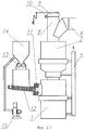
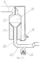
на фиг.1 - двухкамерная печь, вертикальный разрез; на фиг.2 - общий вид установки.figure 1 - two-chamber furnace, a vertical section; figure 2 is a General view of the installation.
Вертикально расположенная печь состоит из двух совмещенных камер 1 и 2 соответственно сгорания кускового твердого или жидкого (предпочтительно комкового) материала и дожигания продуктов их горения.A vertically arranged furnace consists of two combined
Камеры 1 и 2 связаны посредством сопла 3 (фиг.1), выполненного в форме сужения перемычки между ними, причем верхние торцы обеих камер 1, 2 имеют прямоугольный профиль, образуя застойные зоны А и Б борова дымоходов, коммутирующих соответственно камеру 1 с камерой 2 посредством сопла 3 и камеру 2 с перпендикулярно расположенным отводящим трубопроводом 4 (фиг.1 и 2).The
Вдоль печи расположен воздуховод 5 подачи избыточного окисляющего воздуха распределенно в оптимизированном массовом соотношении по высоте, а именно: под колосник 6 - четверть, в камеру 1 сгорания 10-15 мас.%, в сопло 3 половину и в камеру 2 дожигания 10-15 мас.%. При этом каналы 7 подачи окисляющего воздуха в сопло 3 выполнены наклоненными в сторону камеры 2 дожигания под углом 30° к вертикали.Along the furnace there is a
На камере 2 дожигания закреплен технологический патрубок 8, который закрыт шарнирно смонтированной откидной заслонкой 9, связанной через рычаг 10 с приводом поворота, предпочтительно ручным.A
Бункер 11 загрузки камеры 1 сгорания дискретным твердым материалом и/или комкованным жидким материалом сообщается с питающим шнеком 12 (фиг.2), который установлен под роторным измельчителем 13 твердого крупногабаритного материала, предназначенного для сжигания в печи.The
Загрузочный бункер 14 роторного измельчителя 13 подключен к вытяжному вентилятору 15, выход которого сообщается с каналом воздуховода 5 подачи окисляющего воздуха под колосник 6 печи.The
Укрепленный перпендикулярно к печи 2 дожигания отводящий трубопровод 4 связывает ее со скруббером 16, центральная форсунка 17 которого сообщается посредством насоса 18 с емкостью 19 воды, установленной на отводящем патрубке 20, сообщающемся с трубопроводом 21.The
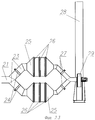
Отводящий трубопровод 21, оснащенный нагнетающим вентилятором 22, сообщается посредством двух автономных ручьев 23 через шиберные заслонки 24 с параллельными устройствами 25 фильтрования отходящего аэрозоля, каждое из которых представляет собой каскад сменных кассет 26, выполненных из волокнистого фильтрующего материала, в частности из базальтового волокна.The
Выход ручьев 23, перекрытый шиберными заслонками 27, связан с дымовой трубой 28 через вытяжной вентилятор 29.The output of the
Функционирует устройство следующим образом.The device operates as follows.
Для розжига печи (при открытой заслонке 9 на патрубке 8) используют загрузку топочного объема камеры 1 дровами, стружкой, щепой и пр., при сжигании которых обеспечивается подъем температуры до рабочего уровня 1200-1400°С, после чего закрывают заслонку 9 и осуществляют загрузку дробного материала роторным питателем 12.To ignite the furnace (with the
Газы режима розжига выпускаются наружу через открытый патрубок 8 печи.The gases of the ignition mode are released out through the
Материалы для сжигания загружают непосредственно в роторный питатель 12 или в бункер 14 (в случае подачи крупногабаритных твердых материалов или упаковок в массивные коробки). В роторном измельчителе 13 материалы из бункера 14 фрагментируются до установленных размеров и поступают в шнековый питатель 12, которым они уплотняются и подаются в загрузочный бункер 11 камеры 1 сгорания.Combustion materials are loaded directly into the
Сформированная в бункере 11 плотная масса загружаемого материала имеет большое аэродинамическое сопротивление и выполняет функции газовой задвижки, что позволяет осуществлять непрерывную загрузку печи, сопоставимую по массе с расходом сжигаемого материала в камере 1 сжигания, помещенного на колосниках 6.The dense mass of the feed material formed in the
При этом под колосники 6 из воздуховода 5 подается окислительный воздух, который распределенно поступает в объем сжигаемого дискретного материала, увеличивая площадь горения и активизируя процесс горения и подъем температуры.In this case, oxidizing air is supplied under the
Дополнительный объем избыточного воздуха подается и непосредственно в камеру 1 сгорания из воздуховода 5 поперечными струями, что способствует перемешиванию отходящих газовых продуктов горения с вторичным воздухом.An additional volume of excess air is supplied directly to the
Продукты пиролиза тормозятся прямоугольным боровом верхней части камеры 1 сгорания в зоне А и задерживаются в ней на время не менее 2 с, что является достаточным для окисления сажи как наиболее инертной и трудносжигаемой составляющей любого слоевого сжигания.The pyrolysis products are inhibited by the rectangular bore of the upper part of the
Направленные по наклоненным в камеру 2 дожигания каналам 7 струи окисляющего воздуха из воздуховода 5 создают в сопле 3 разрежение, в результате чего отходящие газы по центру камеры 1 сгорания всасываются и поступают в камеру 2 дожигания, где тормозятся, расширяясь, и дополнительно - посредством поперечных струй воздуха из воздуховода 5.The oxidizing air jets directed from the
Активно перемешиваясь с окисляющим воздухом, аэрозольные продукты горения дожигаются до конечных продуктов, чему способствует застойная зона Б прямоугольного борова верхней части камеры 2 дожигания, который обеспечивает время пребывания в ней смеси не менее 2 с.Actively mixing with oxidizing air, the aerosol combustion products are burned to the final products, which is facilitated by the stagnant zone B of the rectangular bore of the upper part of the
Дутье окисляющего воздуха оптимально распределено в следующем массовом соотношении: 45-50% в сопло 3, 20-25% под колосник 6 и по 10-15% в обе камеры 1, 2, что создает положительный кислородный баланс (30-50%) в процессе сжигания горючей смеси.The blasting of oxidizing air is optimally distributed in the following mass ratio: 45-50% into
Предложенная конструкция печи и термодинамический режим горения в ней оптимизированы для полного сжигания различных материалов при окислении компонентов до конечных продуктов, о чем свидетельствует практически полное отсутствие в отходящем аэрозоле трубопровода 4 сажи.The proposed furnace design and the thermodynamic combustion regime in it are optimized for the complete combustion of various materials during the oxidation of the components to final products, as evidenced by the almost complete absence of 4 soot pipelines in the exhaust aerosol.
В печи возможно сжигать твердые органические бытовые и производственные отходы, токсичные больничные отходы, содержащие использованные бинты, вату, одноразовые шприцы, иглы, ампулы, флаконы, системы переливания крови, резиновые трубки, перчатки и т.п. материалы.In the furnace it is possible to burn solid organic household and industrial waste, toxic hospital waste containing used bandages, cotton wool, disposable syringes, needles, ampoules, vials, blood transfusion systems, rubber tubes, gloves, etc. materials.
В трубопроводе 4 газовый поток с температурой 1100-1200°С разворачивается и при этом тормозится, поступая в скруббер 16, где происходит резкое снижение температуры аэрозоля за счет испарительного охлаждения диспергируемой форсункой 17 воды до уровня 250-300°С.In the
Парогазовая смесь из скруббера 16 поступает через центральный патрубок 20 в трубопровод 21, где посредством вентилятора 22, нагнетающего воздух в устройство 25 фильтрования, осуществляется принудительное перемешивание аэрозоля с воздухом при снижении температуры до 120-140°С.The gas-vapor mixture from the
Из трубопровода 22 аэрозоль по открытому ручью 23 (при выдвинутых шиберных заслонках 24 и 27) подается в устройство 25, где проходит каскад фильтрующих кассет 26, в которых на волокнистом газопроницаемом материале задерживаются твердые зольные частицы.From the
Чистые газообразные отходящие продукты выводятся в трубу 28 посредством насоса 28 и далее поступают в атмосферу.Pure gaseous waste products are discharged into the
Периодически в устройстве 25 шиберные заслонки 24 и 27 перекрывают, открывая аналогичные шиберные заслонки 24, 27 второго ручья 23, подключая тем самым дублирующее устройство 25 фильтрования в работу.Periodically in the
В отключенном устройстве 25 кассеты 26 заменяют на чистые, подготавливая его к последующей работе. Таким образом смена фильтрующих кассет 26 осуществляется без прерывания технологического процесса установки.In the
Успешные испытания опытного образца установки по изобретению на различных режимах сжигания разнообразных твердых и жидких материалов, аттестованные контрольно-измерительной аппаратурой, позволяют рекомендовать ее к серийному производству для поставки заказчикам.Successful testing of a prototype of the installation according to the invention in various modes of burning a variety of solid and liquid materials, certified by instrumentation, allows us to recommend it for mass production for delivery to customers.
Claims (3)
Priority Applications (1)
| Application Number | Priority Date | Filing Date | Title |
|---|---|---|---|
| RU2009105925/03A RU2392544C1 (en) | 2009-02-24 | 2009-02-24 | Furnace for combustion of solid and fuel materials |
Applications Claiming Priority (1)
| Application Number | Priority Date | Filing Date | Title |
|---|---|---|---|
| RU2009105925/03A RU2392544C1 (en) | 2009-02-24 | 2009-02-24 | Furnace for combustion of solid and fuel materials |
Publications (1)
| Publication Number | Publication Date |
|---|---|
| RU2392544C1 true RU2392544C1 (en) | 2010-06-20 |
Family
ID=42682832
Family Applications (1)
| Application Number | Title | Priority Date | Filing Date |
|---|---|---|---|
| RU2009105925/03A RU2392544C1 (en) | 2009-02-24 | 2009-02-24 | Furnace for combustion of solid and fuel materials |
Country Status (1)
| Country | Link |
|---|---|
| RU (1) | RU2392544C1 (en) |
Cited By (5)
| Publication number | Priority date | Publication date | Assignee | Title |
|---|---|---|---|---|
| RU167434U1 (en) * | 2016-05-25 | 2017-01-10 | Николай Васильевич Попов | HIGH TEMPERATURE INVERTER TWO-WAY BURNER |
| RU2660966C1 (en) * | 2017-09-13 | 2018-07-11 | Александр Григорьевич Ершов | Vertical furnace |
| RU2685720C1 (en) * | 2018-06-28 | 2019-04-23 | Александр Григорьевич Ершов | Solid wastes combustion plant |
| RU2686560C1 (en) * | 2018-08-15 | 2019-04-29 | Александр Григорьевич Ершов | Solid wastes combustion method |
| RU195620U1 (en) * | 2019-10-25 | 2020-02-03 | Алексей Леонидович Торопов | CASCADE CASSETTE BOILER SMOKE PIPE COLLECTOR |
-
2009
- 2009-02-24 RU RU2009105925/03A patent/RU2392544C1/en not_active IP Right Cessation
Cited By (5)
| Publication number | Priority date | Publication date | Assignee | Title |
|---|---|---|---|---|
| RU167434U1 (en) * | 2016-05-25 | 2017-01-10 | Николай Васильевич Попов | HIGH TEMPERATURE INVERTER TWO-WAY BURNER |
| RU2660966C1 (en) * | 2017-09-13 | 2018-07-11 | Александр Григорьевич Ершов | Vertical furnace |
| RU2685720C1 (en) * | 2018-06-28 | 2019-04-23 | Александр Григорьевич Ершов | Solid wastes combustion plant |
| RU2686560C1 (en) * | 2018-08-15 | 2019-04-29 | Александр Григорьевич Ершов | Solid wastes combustion method |
| RU195620U1 (en) * | 2019-10-25 | 2020-02-03 | Алексей Леонидович Торопов | CASCADE CASSETTE BOILER SMOKE PIPE COLLECTOR |
Similar Documents
| Publication | Publication Date | Title |
|---|---|---|
| JP2528426B2 (en) | Combustion chamber for burning bulk trash and liquids containing hydrocarbons | |
| CN103363531B (en) | A kind of dangerous waste incinerator complexes | |
| JP4889176B2 (en) | Method and apparatus for burning solid fuel, especially solid waste | |
| CN203628674U (en) | Whole-set hazardous waste incinerator device | |
| RU2392544C1 (en) | Furnace for combustion of solid and fuel materials | |
| KR101417233B1 (en) | Method for incinerating waste by two-stage swirling flow fluidized bed incinerator | |
| CN207999834U (en) | A kind of medical waste pyrolysis gasification furnace incinerator | |
| CN206469273U (en) | A kind of organic waste gas treatment device | |
| CN110360575A (en) | A kind of incineration system at dangerous waste disposition center | |
| CN102537976A (en) | Rotation burning type burning device and waste disposal method | |
| CN102317687A (en) | Be used to handle the method and apparatus of solid waste | |
| RU2387926C1 (en) | Vertical furnace | |
| JP2008057906A (en) | Low pollution incinerating device | |
| RU83827U1 (en) | FURNACE FOR BURNING SOLID AND LIQUID MATERIALS | |
| CN208487625U (en) | A kind of novel combination type solid-liquid incineration furnace | |
| CN105861000A (en) | Discharging method for high-temperature carbonized material | |
| CN107941030B (en) | Primary air injection structure and process of rotary kiln waste gas treatment device | |
| KR100893389B1 (en) | Heat recovering system having conbustion apparatus | |
| CN107120665A (en) | A kind of salt bearing liquid wastes processing unit and method | |
| RU2357151C1 (en) | Device for thermal sterilisation of toxic chemicals | |
| CN105674272A (en) | Silicon ceramic grate compound incineration furnace and processing technology thereof | |
| CN2386329Y (en) | Incinerator with built-in tertiary combustion chamber | |
| KR100249104B1 (en) | Method and apparatus for burning out industrial wastes | |
| CN2399609Y (en) | Garbage incineration equipment | |
| CN207065589U (en) | A kind of salt bearing liquid wastes processing unit |
Legal Events
| Date | Code | Title | Description |
|---|---|---|---|
| MM4A | The patent is invalid due to non-payment of fees |
Effective date: 20110225 |