RU2391503C2 - Method and device to analyse fluid - Google Patents
Method and device to analyse fluid Download PDFInfo
- Publication number
- RU2391503C2 RU2391503C2 RU2006114647/03A RU2006114647A RU2391503C2 RU 2391503 C2 RU2391503 C2 RU 2391503C2 RU 2006114647/03 A RU2006114647/03 A RU 2006114647/03A RU 2006114647 A RU2006114647 A RU 2006114647A RU 2391503 C2 RU2391503 C2 RU 2391503C2
- Authority
- RU
- Russia
- Prior art keywords
- fluid
- cavity
- evaluation
- downhole tool
- test chamber
- Prior art date
Links
Images

Classifications
-
- E—FIXED CONSTRUCTIONS
- E21—EARTH OR ROCK DRILLING; MINING
- E21B—EARTH OR ROCK DRILLING; OBTAINING OIL, GAS, WATER, SOLUBLE OR MELTABLE MATERIALS OR A SLURRY OF MINERALS FROM WELLS
- E21B49/00—Testing the nature of borehole walls; Formation testing; Methods or apparatus for obtaining samples of soil or well fluids, specially adapted to earth drilling or wells
- E21B49/08—Obtaining fluid samples or testing fluids, in boreholes or wells
- E21B49/10—Obtaining fluid samples or testing fluids, in boreholes or wells using side-wall fluid samplers or testers
Landscapes
- Geology (AREA)
- Life Sciences & Earth Sciences (AREA)
- Engineering & Computer Science (AREA)
- Mining & Mineral Resources (AREA)
- Environmental & Geological Engineering (AREA)
- Fluid Mechanics (AREA)
- Physics & Mathematics (AREA)
- General Life Sciences & Earth Sciences (AREA)
- Geochemistry & Mineralogy (AREA)
- Sampling And Sample Adjustment (AREA)
- Testing Of Devices, Machine Parts, Or Other Structures Thereof (AREA)
- Measuring Fluid Pressure (AREA)
- Geophysics And Detection Of Objects (AREA)
Abstract
Description
Настоящее изобретение относится к технологиям проведения оценки подземной формации с помощью скважинного инструмента, размещенного в стволе скважины, проходящей в подземной формации. Более конкретно, но не в качестве ограничения, настоящее изобретение относится к технологиям проведения измерений флюидов формации.The present invention relates to techniques for assessing an underground formation using a downhole tool located in a wellbore passing in an underground formation. More specifically, but not by way of limitation, the present invention relates to technologies for measuring formation fluids.
Скважины бурятся для определения местонахождения и добычи углеводородов. Скважинный буровой инструмент с буровой коронкой на его конце углубляется в землю для образования ствола скважины. По мере углубления бурового инструмента буровой раствор прокачивается через буровой инструмент и выходит из буровой коронки для охлаждения бурового инструмента и для удаления шлама. Буровой раствор дополнительно образует фильтрационную корку, которая покрывает ствол скважины.Wells are drilled to locate and produce hydrocarbons. A downhole drilling tool with a drill bit at its end is sunk into the ground to form a borehole. As the drilling tool deepens, the drilling fluid is pumped through the drilling tool and exits the drill bit to cool the drilling tool and to remove sludge. The drilling fluid additionally forms a filter cake that covers the wellbore.
Во время буровых работ желательно выполнять различные оценки формации, пройденной стволом скважины. В некоторых случаях буровой инструмент должен быть вынут, и инструмент может быть спущен в ствол скважины на тросе для испытания и/или отбора проб формации. В других случаях буровой инструмент может снабжаться устройством для испытания и/или отбора проб окружающей формации, и буровой инструмент может быть использован для выполнения испытания или отбора проб. Эти пробы или испытания могут быть использованы, например, для определения местонахождения полезных углеводородов.During drilling operations, it is desirable to perform various assessments of the formation traversed by the wellbore. In some cases, the drilling tool must be removed and the tool may be lowered into the wellbore on a cable for testing and / or sampling the formation. In other cases, the drilling tool may be provided with a device for testing and / or sampling the surrounding formation, and the drilling tool may be used to perform testing or sampling. These samples or tests can be used, for example, to locate useful hydrocarbons.
Оценка формации зачастую требует, чтобы флюид из формации был извлечен в скважинный инструмент для испытания и/или отбора проб. Различные устройства, такие как зонды, выдвигаются из скважинного инструмента для установления взаимодействия с флюидом формации, окружающей ствол скважины, и для извлечения флюида в скважинный инструмент. Типичным зондом является цилиндрический элемент, выдвинутый из скважинного инструмента и размещенный напротив боковой стенки ствола скважины. Резиновый уплотнитель на конце зонда используется для создания уплотнения со стенкой ствола скважины. Другое устройство, используемое для образования уплотнения со стволом скважины, называется двойным уплотнителем. С использованием двойного уплотнителя два эластомерных кольца натягиваются на инструмент, чтобы изолировать часть ствола скважины между ними. Кольца образуют уплотнение со стенкой ствола скважины и позволяют флюиду попадать в изолированную часть ствола скважины и во впускное отверстие в скважинном инструменте.Formation assessment often requires that the fluid from the formation be removed into the downhole tool for testing and / or sampling. Various devices, such as probes, extend from the downhole tool to establish interaction with the formation fluid surrounding the wellbore and to extract the fluid into the downhole tool. A typical probe is a cylindrical element extended from a downhole tool and placed opposite the side wall of the wellbore. A rubber seal at the end of the probe is used to create a seal with the borehole wall. Another device used to form a seal with a wellbore is called a double seal. Using a double seal, two elastomeric rings are pulled onto the tool to isolate part of the wellbore between them. The rings form a seal with the wall of the wellbore and allow fluid to enter the isolated part of the wellbore and into the inlet in the downhole tool.
Фильтрационная корка, покрывающая ствол скважины, часто оказывает содействие зонду и/или двойному уплотнителю в создании уплотнения со стенкой ствола скважины. Когда уплотнение сделано, флюид из формации извлекается в скважинный инструмент через впускное отверстие из-за понижения давления в скважинном инструменте. Примеры зондов и/или уплотнителей, используемых в скважинных инструментах, описаны в патентах США №№6301959; 4860581; 4936139; 6585045; 6609568 и 6719049 и заявке на патент США №2004/0000433.The filter cake covering the wellbore often assists the probe and / or double seal in creating a seal with the wall of the wellbore. When the seal is done, fluid from the formation is removed into the downhole tool through the inlet due to a decrease in pressure in the downhole tool. Examples of probes and / or seals used in downhole tools are described in US Pat. Nos. 6,301,959; 4,860,581; 4,936,139; 6,550,045; 6609568 and 6719049 and application for US patent No. 2004/0000433.
Оценка формации обычно выполняется на флюиде, извлеченном в скважинный инструмент. В настоящий момент существуют технологии выполнения различных измерений, предварительных испытаний и/или отбора проб флюида, который поступает в скважинный инструмент.Formation assessment is usually performed on the fluid extracted into the downhole tool. Currently, there are technologies for performing various measurements, preliminary tests and / or sampling of fluid that enters the downhole tool.
Флюид, проходящий через скважинный инструмент, может быть испытан для определения различных скважинных параметров или свойств. Различные свойства углеводородных флюидов резервуара, такие как вязкость, плотность и фазовое поведение флюида в условиях резервуара, могут быть использованы для оценки потенциальных запасов, определения потока в пористой среде и проектирование конструкции систем завершения, отделения, обработки и измерения, среди прочего.The fluid passing through the downhole tool can be tested to determine various downhole parameters or properties. Various properties of reservoir hydrocarbon fluids, such as viscosity, density, and phase behavior of the fluid under reservoir conditions, can be used to evaluate potential reserves, determine flow in a porous medium, and design the completion, separation, processing, and measurement systems, among others.
Дополнительно, пробы флюида могут быть собраны в скважинном инструменте и извлечены на поверхность. Скважинный инструмент хранит флюиды формации в одной или более отборных камерах или баллонах для образцов и извлекает баллоны на поверхность с флюидом формации, находящимся под давлением. Пример такого типа отбора проб описан в патенте США №6688390. Такие пробы иногда называются живыми флюидами. Такие флюиды могут затем быть отправлены в подходящую лабораторию для дальнейшего анализа. Обычный анализ или определение параметров флюида может включать, например, анализ состава, свойств флюида и фазового поведения. В некоторых случаях такой анализ может быть также осуществлен на поверхности скважины c использованием передвижной лабораторной системы. Разработаны технологии для выполнения испытаний живого флюида на поверхности. Многие измерения флюида могут требовать времени порядка часа и более. Например, при анализе или обнаружении фазового поведения флюид начинает с одного состояния, жидкого или газового. Температура поддерживается постоянной. Объем увеличивается серией малых шагов. Перед выполнением следующего шага по изменению объема давление должно быть стабильным. Для уменьшения времени, требующегося для стабилизации давления, флюид активно перемешивается. Такое перемешивание обычно включает размешивание, взбалтывание, сдвиг, вибрацию, и/или другое перемещение объема флюида. Во время процесса или шагов увеличения объема используются оптические технологии для определения присутствия раздельных фаз. Например, камера высокого давления с 2-микронным разрешением может быть использована для получения изображений через оптическое окно, и могут быть сделаны измерения поглощения света с использованием ближней инфракрасной области спектра.Additionally, fluid samples can be collected in a downhole tool and taken to the surface. The downhole tool stores formation fluids in one or more sample chambers or sample cylinders and removes the cylinders to the surface with the formation fluid under pressure. An example of this type of sampling is described in US Pat. No. 6,688,390. Such samples are sometimes called living fluids. Such fluids can then be sent to a suitable laboratory for further analysis. A routine analysis or determination of fluid parameters may include, for example, analysis of composition, fluid properties, and phase behavior. In some cases, such an analysis can also be carried out on the surface of the well using a mobile laboratory system. Technologies have been developed to test live fluid on the surface. Many fluid measurements may require times of the order of an hour or more. For example, when analyzing or detecting phase behavior, the fluid begins with a single state, liquid or gas. The temperature is kept constant. Volume is increased by a series of small steps. Before performing the next volume change step, the pressure must be stable. To reduce the time required to stabilize the pressure, the fluid is actively mixed. Such mixing typically involves stirring, shaking, shearing, vibration, and / or other movement of the fluid volume. During the process or steps of increasing the volume, optical technologies are used to determine the presence of separate phases. For example, a 2 micron high-pressure chamber can be used to obtain images through an optical window, and light absorption measurements can be made using the near infrared region of the spectrum.
Во время взятия проб флюид резервуара может демонстрировать множество фазовых переходов. Часто эти переходы являются результатом охлаждения, падения давления и/или изменений состава, которые происходят, когда флюид извлекается в инструмент и/или извлекается на поверхность. Определение характеристик фазового поведения флюида является ключевым при планировании и оптимизации разработки и добычи месторождения. Изменения температуры (T) и давления (P) флюида формации часто влечет многофазное разделение (например, жидкость-пар, жидкость-твердое вещество, жидкость-жидкость, пар-жидкость и так далее) и рекомбинацию фаз. Подобным образом однофазный газ обычно имеет огибающую, на которой отделяется жидкая фаза, известную как точка конденсации. Эти изменения могут помешать измерениям, проводящимся во время оценки формации. Более того, имеется значительная задержка во времени между отбором проб и испытанием на поверхности или в сторонних лабораториях.During sampling, the fluid in the reservoir can exhibit many phase transitions. Often these transitions are the result of cooling, pressure drop and / or compositional changes that occur when the fluid is removed into the tool and / or removed to the surface. Determining the phase behavior of the fluid is key in planning and optimizing field development and production. Changes in the temperature (T) and pressure (P) of the formation fluid often result in multiphase separation (for example, liquid-vapor, liquid-solid, liquid-liquid, vapor-liquid, etc.) and phase recombination. Similarly, a single-phase gas usually has an envelope at which the liquid phase, known as the condensation point, separates. These changes may interfere with measurements taken during formation assessment. Moreover, there is a significant delay in time between sampling and testing on the surface or in third-party laboratories.
Поэтому желательно создать технологии, способные выполнять оценку флюида формации. Дополнительно желательно, чтобы такие технологии обеспечивали точные измерения в реальном режиме времени. Такая оценка формации может потребоваться для работы при размерных и временных ограничениях операций в стволе скважины и предпочтительно выполняться в скважине. Такое устройство для анализа флюида, способное осуществлять такую оценку формации, создано настоящим изобретением.Therefore, it is desirable to create technologies capable of evaluating the formation fluid. Additionally, it is desirable that such technologies provide accurate measurements in real time. Such an assessment of the formation may be required to operate under dimensional and time constraints of operations in the wellbore and is preferably performed in the well. Such a fluid analysis apparatus capable of performing such an assessment of a formation is provided by the present invention.
По меньшей мере в одном аспекте настоящее изобретение относится к устройству для анализа флюида. Это устройство включает испытательную камеру, приспособленную для перемещения флюида, нагнетательный узел и, по меньшей мере, один датчик. Испытательная камера образует оценочную полость для приема флюида. Приспособление для перемещения флюида имеет силовое средство, прикладывающее усилие к флюиду, заставляя флюид перемещаться внутри полости. Нагнетательный узел непрерывно изменяет давление флюида. По меньшей мере, один датчик взаимодействует с флюидом для определения, по меньшей мере, одного параметра флюида во время непрерывного изменения давления флюида.In at least one aspect, the present invention relates to a fluid analysis apparatus. This device includes a test chamber adapted to move the fluid, an injection unit and at least one sensor. The test chamber forms an evaluation cavity for receiving fluid. The fluid transfer device has a force that applies force to the fluid, causing the fluid to move within the cavity. The injection unit continuously changes the fluid pressure. At least one sensor interacts with a fluid to determine at least one fluid parameter during a continuous change in fluid pressure.
В одном варианте осуществления, испытательная камера выполнена как канал, такой как петля рециркуляции. В другом варианте осуществления, испытательная камера включает канал, обводную петлю, сообщающуюся с каналом и образующую оценочную полость, и, по меньшей мере, один клапан, размещенный между каналом и оценочной полостью обводной петли для выборочного отвода флюида в оценочную полость обводной петли из канала.In one embodiment, the test chamber is configured as a channel, such as a recirculation loop. In another embodiment, the test chamber includes a channel, a bypass loop in communication with the channel and forming an evaluation cavity, and at least one valve located between the channel and the evaluation loop of the bypass loop to selectively divert fluid into the evaluation cavity of the bypass loop from the channel.
В еще одном варианте осуществления, приспособление для перемещения флюида включает насос. Необязательно, приспособление для перемещения флюида включает перемешивающий элемент, расположенный в оценочной полости и формирующий во флюиде завихрение. В этом варианте осуществления, по меньшей мере, один датчик желательно расположен внутри вихря.In yet another embodiment, the fluid transfer device includes a pump. Optionally, the fluid transfer device includes a mixing element located in the evaluation cavity and forming a swirl in the fluid. In this embodiment, at least one sensor is desirably located within the vortex.
В еще одном варианте осуществления, приспособление для перемещения флюида и нагнетательный модуль выполнены как единое целое и вместе содержат первый корпус, второй корпус, первый поршень и второй поршень. Первый корпус образует первую полость, сообщающуюся с оценочной полостью в испытательной камере. Второй корпус образует вторую полость, сообщающуюся с оценочной полостью в испытательной камере. Первая полость имеет площадь поперечного сечения большую, чем площадь поперечного сечения второй полости. Первый поршень расположен в первой полости и может перемещаться в первой полости. Второй поршень расположен во второй полости и может перемещаться во второй полости. Перемещение первого и второго поршней синхронизировано для одновременного перемещения флюида и изменения давления в испытательной камере.In yet another embodiment, the fluid transfer device and the injection module are integrally formed and together comprise a first housing, a second housing, a first piston and a second piston. The first body forms the first cavity in communication with the evaluation cavity in the test chamber. The second body forms a second cavity communicating with the evaluation cavity in the test chamber. The first cavity has a cross-sectional area larger than the cross-sectional area of the second cavity. The first piston is located in the first cavity and can move in the first cavity. The second piston is located in the second cavity and can move in the second cavity. The movement of the first and second pistons is synchronized to simultaneously move the fluid and change the pressure in the test chamber.
В варианте осуществления, спроектированном для обнаружения изменений фаз флюида, по меньшей мере, один датчик желательно включает датчик давления, датчик температуры, датчик точки кипения. Датчик давления считывает показания давления внутри оценочной полости в испытательной камере. Датчик температуры считывает показания температуры флюида внутри оценочной полости в испытательной камере. Датчик точки кипения обнаруживает образование пузырьков внутри флюида.In an embodiment designed to detect fluid phase changes, the at least one sensor desirably includes a pressure sensor, a temperature sensor, and a boiling point sensor. The pressure sensor reads the pressure inside the evaluation chamber in the test chamber. The temperature sensor reads the temperature of the fluid inside the evaluation cavity in the test chamber. The boiling point sensor detects the formation of bubbles inside the fluid.
В другом аспекте, настоящее изобретение относится к скважинному инструменту, размещаемому в стволе скважины, имеющем стенку и проходящем в подземную формацию. Формация содержит флюид. Скважинный инструмент включает корпус, приспособление для сообщения с флюидом и устройство для анализа флюида. Приспособление для сообщения с флюидом способно выдвигаться из корпуса для обеспечения плотного контакта со стенкой ствола скважины. Приспособление для сообщения с флюидом имеет, по меньшей мере, одно впускное отверстие для приема флюида из формации. Устройство для анализа флюида расположено внутри корпуса. Это устройство включает испытательную камеру, приспособление для перемещения флюида, нагнетательный узел и, по меньшей мере, один датчик. Испытательная камера образует оценочную полость для приема флюида из приспособления для сообщения с флюидом. Приспособление для перемещения флюида имеет силовое средство, прикладывающее усилие к флюиду, заставляя флюид перемещаться внутри полости. Нагнетательный узел изменяет давление флюида. По меньшей мере, один датчик взаимодействует с флюидом для определения, по меньшей мере, одного параметра флюида. Устройство для анализа флюида может быть любым из описанных выше вариантов его осуществления.In another aspect, the present invention relates to a downhole tool located in a wellbore having a wall and extending into an underground formation. The formation contains fluid. The downhole tool includes a housing, a fluid communication device, and a fluid analysis device. The fluid communication device is able to extend out of the body to provide tight contact with the wall of the wellbore. The fluid communication device has at least one inlet for receiving fluid from the formation. A fluid analysis device is located inside the housing. This device includes a test chamber, a device for moving fluid, an injection unit and at least one sensor. The test chamber forms an evaluation cavity for receiving fluid from the fluid communication device. The fluid transfer device has a force that applies force to the fluid, causing the fluid to move within the cavity. The injection unit changes the fluid pressure. At least one sensor interacts with a fluid to determine at least one fluid parameter. The fluid analysis device may be any of the embodiments described above.
В одном варианте осуществления приспособление для сообщения с флюидом включает, по меньшей мере, два впускных отверстия, при этом одно из впускных отверстий принимает чистый флюид из формации. В этом варианте осуществления скважинный инструмент дополнительно содержит канал, принимающий чистый флюид из одного из впускных отверстий приспособления для сообщения с флюидом, и подает чистый флюид в оценочную полость.In one embodiment, the fluid communication device includes at least two inlets, wherein one of the inlets receives clean fluid from the formation. In this embodiment, the downhole tool further comprises a channel receiving clean fluid from one of the inlets of the fluid communication device, and delivers clean fluid to the evaluation cavity.
Настоящее изобретение также относится к способу для измерения параметров неизвестного флюида внутри ствола скважины, проходящей в формации, содержащей флюид. В этом способе приспособление для сообщения с флюидом скважинного инструмента расположено в плотном контакте со стенкой ствола скважины. Флюид извлекается из формации в оценочную полость внутри скважинного инструмента и перемещается внутри оценочной полости, при этом данные собираются, пока флюид перемещается внутри оценочной полости.The present invention also relates to a method for measuring unknown fluid inside a wellbore in a formation containing a fluid. In this method, the device for communicating with the fluid of the downhole tool is located in close contact with the wall of the wellbore. The fluid is extracted from the formation into the evaluation cavity within the downhole tool and moves within the evaluation cavity, with data being collected while the fluid moves inside the evaluation cavity.
В одном варианте осуществления способа давление внутри оценочной полости непрерывно изменяется при сборе данных.In one embodiment of the method, the pressure within the evaluation cavity continuously changes during data collection.
В другом варианте осуществления способа точка кипения флюида определяется на основании собранных данных.In another embodiment of the method, the boiling point of the fluid is determined based on the collected data.
В еще одном варианте осуществления способа оценочная полость образуется как обводная петля из главного канала, и способ дополнительно содержит этапы отвода флюида из главного канала в отдельную оценочную полость, циркуляции отведенного флюида внутри отдельной оценочной полости, и сбора данных об отведенном флюиде внутри отдельной оценочной полости во время циркуляции отведенного флюида.In yet another embodiment of the method, the evaluation cavity is formed as a bypass loop from the main channel, and the method further comprises the steps of diverting fluid from the main channel to a separate evaluation cavity, circulating the diverted fluid within a separate evaluation cavity, and collecting data on the diverted fluid inside a separate evaluation cavity in the circulation time of the allotted fluid.
В дополнительном варианте осуществления флюиды, находящиеся в отдельных оценочных полостях, могут быть смешаны и затем смешанный флюид может рециркулировать. Затем собираются данные о смешанном флюиде во время рециркуляции смешанного флюида.In a further embodiment, the fluids located in the separate evaluation cavities may be mixed and then the mixed fluid may be recycled. Then mixed fluid data is collected during the mixed fluid recirculation.
В одном аспекте, приспособление для сообщения с флюидом является двойным уплотнителем и неизвестный флюид является чистым флюидом.In one aspect, the fluid communication device is a dual sealant and the unknown fluid is pure fluid.
Так, чтобы вышеизложенные признаки и преимущества настоящего изобретения могли быть поняты в подробностях, более конкретное описание изобретения, кратко изложенное выше, может служить для ссылки на варианты его осуществления, которые проиллюстрированы на прилагаемых чертежах. Однако следует отметить, что прилагаемые чертежи иллюстрируют только типичные варианты осуществления этого изобретения и поэтому не могут рассматриваться как ограничивающие их объем, и что для изобретения допускаются другие, в равной степени эффективные варианты осуществления.So that the foregoing features and advantages of the present invention can be understood in detail, a more specific description of the invention, summarized above, can serve to refer to options for its implementation, which are illustrated in the accompanying drawings. However, it should be noted that the accompanying drawings illustrate only typical embodiments of this invention and therefore cannot be construed as limiting their scope, and that other, equally effective embodiments are allowed for the invention.
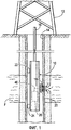
Фиг.1 является схематическим видом частичного поперечного сечения скважинного инструмента, имеющего устройство для анализа флюида и опущенного в скважину с буровой установки.Figure 1 is a schematic view of a partial cross section of a downhole tool having a fluid analysis device and lowered into a well from a drilling rig.
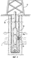
Фиг.2 является схематическим видом частичного поперечного сечения скважинного бурового инструмента, имеющего устройство для анализа флюида и опущенного в скважину с буровой установки.Figure 2 is a schematic view of a partial cross section of a downhole drilling tool having a fluid analysis device and lowered into a well from a drilling rig.
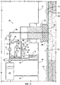
Фиг.3 является схематическим представлением части скважинного инструмента, изображенного на фиг.1, имеющего зонд, установленный напротив боковой стенки ствола скважины и оценочный канал устройства для анализа флюида, сообщающийся с внутренним каналом, доставляющим флюид формации из зонда.FIG. 3 is a schematic representation of a portion of the downhole tool of FIG. 1 having a probe mounted opposite a side wall of a wellbore and an evaluation channel of a fluid analysis device in communication with an internal channel delivering formation fluid from the probe.
Фиг.4 является схематическим представлением части еще одного варианта осуществления скважинного инструмента, изображенного на фиг.1, имеющего зонд, установленный напротив боковой стенки ствола скважины, и оценочный канал устройства для анализа флюида, сообщающийся с внутренним каналом, доставляющим флюид формации из зонда.FIG. 4 is a schematic representation of a portion of yet another embodiment of the downhole tool of FIG. 1 having a probe mounted opposite a side wall of a wellbore and an evaluation channel of a fluid analysis device in communication with an internal channel delivering formation fluid from the probe.
Фиг.5A является схематическим представлением части другого варианта осуществления скважинного инструмента, изображенного на фиг.1, имеющего зонд, установленный напротив боковой стенки ствола скважины, и оценочный канал устройства для анализа флюида, сообщающийся с внутренним каналом, доставляющим флюид формации из зонда.FIG. 5A is a schematic representation of part of another embodiment of the downhole tool of FIG. 1 having a probe mounted opposite a side wall of a wellbore and an evaluation channel of a fluid analysis device in communication with an internal channel delivering formation fluid from the probe.
Фиг.5B является схематическим представлением скважинного инструмента, изображенного на фиг.5A, показывающим перемещение флюида формации внутри оценочного канала.Fig. 5B is a schematic representation of the downhole tool of Fig. 5A showing the movement of formation fluid within the evaluation channel.
Фиг.6 является схематическим представлением части другого варианта осуществления скважинного инструмента, изображенного на фиг.1, имеющего зонд, установленный напротив боковой стенки ствола скважины, и оценочный канал устройства для анализа флюида, сообщающийся с внутренним каналом, доставляющим флюид формации из зонда.FIG. 6 is a schematic representation of part of another embodiment of the downhole tool of FIG. 1 having a probe mounted opposite a side wall of a wellbore and an evaluation channel of a fluid analysis device in communication with an internal channel delivering formation fluid from the probe.
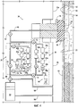
Фиг.7 является схематическим представлением части другого варианта осуществления скважинного инструмента, изображенного на фиг.1, имеющего двойной зонд, установленный напротив боковой стенки скважины, и оценочный канал устройства для анализа флюида, сообщающийся с внутренним каналом, доставляющим флюид формации из зонда.FIG. 7 is a schematic representation of part of another embodiment of the downhole tool of FIG. 1 having a dual probe mounted opposite a side wall of a well and an evaluation channel of a fluid analysis device in communication with an internal channel delivering formation fluid from the probe.
Некоторые термины определены в этом описании при первом их использовании, в то время как некоторые другие используемые в этом описании термины определены ниже.Some terms are defined in this description upon their first use, while some other terms used in this description are defined below.
«Кольцеобразный» означает, относится или образует кольцо, т.е. линию, ленту или размещение в форме замкнутой кривой, такой как окружность или эллипс."Ring-shaped" means refers to or forms a ring, i.e. a line, tape, or placement in the form of a closed curve, such as a circle or ellipse.
«Загрязненный флюид» означает флюид, который обычно является неприемлемым для взятия проб углеводородного флюида и/или оценки потому, что флюид содержит загрязнители, такие как фильтрат из бурового раствора, используемого при бурении скважины.“Contaminated fluid” means a fluid that is generally not acceptable for sampling a hydrocarbon fluid and / or for evaluating because the fluid contains contaminants, such as mud filtrate, used in drilling a well.
«Скважинный инструмент» означает инструменты, помещенные в ствол скважины посредством бурильной колонны, каната, или рулонного трубопровода для выполнения скважинных операций, относящихся к оценке, добыче и/или управлению одной или более исследуемых подземных формаций.“Downhole tool” means tools placed in a borehole through a drill string, rope, or coiled tubing to perform downhole operations related to the evaluation, production, and / or management of one or more of the investigated subterranean formations.
«Оперативно присоединенный» означает прямо или косвенно присоединенный для передачи или проведения информации, усилия, энергии или вещества (включая флюиды).“Operationally connected” means directly or indirectly connected to transmit or conduct information, effort, energy or a substance (including fluids).
«Чистый флюид» означает подземный флюид, который является довольно чистым, первоначальным, природным, незагрязненным или каким-либо другим образом считающийся в области взятия проб и анализа приемлемым образом представляющим данную формацию для правильного взятия проб или оценки углеводорода.“Pure fluid” means a subterranean fluid that is fairly clean, pristine, natural, unpolluted or otherwise considered in the field of sampling and analysis to be an acceptable representation of the formation for proper sampling or hydrocarbon estimation.
«Флюид» означает и «чистый флюид» и «грязный флюид».“Fluid” means both “clean fluid” and “dirty fluid”.
«Непрерывный» означает отмеченный непрерываемым отрезком времени, пространства или последовательности.“Continuous” means marked with an unbroken span of time, space or sequence.
Предпочтительные варианты осуществления изобретения показаны на вышеописанных чертежах и рассмотренных подробно ниже. В описании предпочтительных вариантов осуществления, подобные или одинаковые ссылочные позиции используются для идентификации общих или подобных элементов. Чертежи не обязательно выполнены в масштабе, и некоторые признаки и некоторые виды чертежей могут быть показаны в увеличенном масштабе или схематически для лучшего ясности и выразительности.Preferred embodiments of the invention are shown in the above-described drawings and discussed in detail below. In the description of preferred embodiments, similar or identical reference numbers are used to identify common or similar elements. The drawings are not necessarily drawn to scale, and some features and certain types of drawings may be shown on an enlarged scale or schematically for better clarity and expressiveness.
Фиг.1 изображает скважинный инструмент 10, сконструированный в соответствии с настоящим изобретением, опущенный с буровой установки 12 в ствол 14 скважины. Скважинный инструмент 10 может быть инструментом любого типа, способным выполнять оценку формации, таким как буровой инструмент, рулонный трубопровод или другой скважинный инструмент. Скважинный инструмент 10 является обычным инструментом, спускаемым с буровой установки 12 в ствол 14 скважины с помощью канатного кабеля 16 и расположенным вплотную к формации F. Пример спускаемого на тросе инструмента, который может быть использован, описан в патентах США №№4860581 и 4936139.Figure 1 depicts a
Скважинный инструмент 10 снабжен зондом 18, приспособленным для плотного соединения со стенкой 20 ствола 14 скважины (здесь и далее упоминается как «стенка 20» или «стенка 20 ствола скважины») и извлечения флюида их формации F в скважинный инструмент 10, как указано стрелками. Вспомогательные поршни 22 и 24 содействуют выталкиванию зонда 18 скважинного инструмента относительно стенки 20 ствола скважины. Скважинный инструмент 10 также снабжен устройством 26 для анализа флюида, сконструированным в соответствии с настоящим изобретением для анализа флюида формации. В частности, устройство 26 способно выполнять оценку формации и/или анализ скважинных флюидов, таких как флюиды формации F. Устройство 26 принимает флюид формации из зонда 18 через оценочный канал 46.The
Фиг.2 изображает другой вариант скважинного инструмента 30, сконструированного в соответствии с настоящим изобретением. Скважинный инструмент 30 является буровым инструментом, который может быть перемещен среди одного или нескольких (или может быть сам) буровых инструментов для измерения во время бурения, буровых инструментов для каротажа во время бурения или другого бурового инструмента, который известен специалистам в данной области техники. Скважинный инструмент 30 присоединен к буровой колонне 32, приводимой в движение буровой установкой 12 для образования ствола 14 скважины. Скважинный инструмент 30 включает зонд 18a, приспособленный для плотного соединения со стенкой 20 ствола 14 скважины для извлечения флюида их формации F в скважинный инструмент 30, как указано стрелками. Скважинный инструмент 30 также снабжен устройством 26 для анализа флюида формации, извлеченного в скважинный инструмент 30. Устройство 26 принимает флюид формации из зонда 18a через канал 46.Figure 2 depicts another embodiment of a
В то время как фиг.1 и фиг.2 изображают устройство 26 для анализа флюида в скважинном устройстве, должно быть принято во внимание, что такое устройство может быть обеспечено на буровой площадке или на другом оборудовании для выполнения испытаний флюида. Путем размещения устройства 26 для анализа флюида в скважине, данные о скважинном флюиде могут быть собраны в реальном режиме времени. Однако также может быть желательно и/или необходимо испытать флюиды на поверхности или в другом месте. В этих случаях устройство для анализа флюида может быть размещено в корпусе, перемещаемом в желаемое место. В качестве альтернативы, пробы могут быть доставлены на поверхность или другое место и испытаны в модуле анализа флюида в этом месте. Данные и результаты тестов из различных мест могут быть проанализированы и сравнены.While FIGS. 1 and 2 depict a
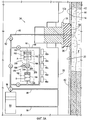
Фиг.3 является схематическим видом части скважинного инструмента 10, изображенного на фиг.1, изображающим систему 34 течения флюида. Зонд 18 предпочтительно выдвигается из корпуса 35 скважинного инструмента 10 для соприкосновения со стенкой 20 ствола скважины. Зонд 18 снабжен уплотнителем 36 для обеспечения плотного контакта со стенкой 20 ствола скважины. Уплотнитель 36 соприкасается со стенкой 20 ствола скважины и образует плотный контакт с фильтрационной коркой 40 бурового раствора, покрывающей ствол 14 скважины. Фильтрационная корка 40 просачивается в стенку 20 ствола скважины и создает зону 42 проникновения вокруг ствола 14 скважины. Зона 42 проникновения содержит буровой раствор и другие флюиды ствола скважины, которые загрязняют окружающие формации, включая в себя формацию F и порцию чистого флюида 44, содержащегося в ней.FIG. 3 is a schematic view of a portion of a
Система 34 течения флюида включает оценочный канал 46, проходящий из впускного отверстия зонда 18. В то время как зонд изображен для извлечения флюида в скважинный инструмент, другие приспособления для сообщения с флюидом могут быть использованы. Примеры приспособлений для сообщения с флюидом, таких как зонды и двойные уплотнители, используемых для извлечения флюида в канал, изображены в патентах США №№4860581 и 4936139.The
Оценочный канал 46 проходит в скважинный инструмент 10 и используется для пропускания флюида, такого как чистый флюид 44, в скважинный инструмент 10 для предварительного испытания, анализа и/или взятия пробы. Оценочный канал 46 проходит в отборную камеру 50 для сбора образцов чистого флюида 44. Система 34 течения флюида может также включать насос 52, используемый для пропускания флюида через канал 46.The
В то время как фиг.3 показывает примерную конфигурацию скважинного инструмента, используемого для извлечения флюида из формации, должно быть принято во внимание специалистом в данной области техники, что может быть использовано множество конфигураций каналов, насосов, отборных камер, клапанов и других устройств, и что это не предназначено для ограничения объема изобретения.While FIG. 3 shows an exemplary configuration of a downhole tool used to extract fluid from a formation, it will be appreciated by one skilled in the art that many configurations of channels, pumps, sampling chambers, valves, and other devices can be used, and that this is not intended to limit the scope of the invention.
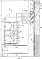
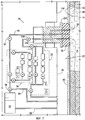
Как обсуждалось выше, скважинное устройство 10 снабжено устройством 26 для анализа флюида формации. В частности, устройство 26 способно осуществлять скважинные измерения, такие как фазовые измерения, измерения вязкости и/или плотности флюида формации. В общем, устройство 26 для анализа флюида снабжено испытательной камерой 60, приспособлением 62 для перемещения флюида, нагнетательным узлом 64 и одним или более датчиками 66 (множество датчиков показаны на фиг.4, 5A, 5B, 6 и 7 и пронумерованы для ясности ссылочными позициями 66a-g).As discussed above, the
Испытательная камера 60 образует оценочную полость 68 для приема флюида формации. Следует понимать, что испытательная камера 60 может иметь любую конфигурацию, способную принимать флюид формации и позволяющую перемещение флюида, как здесь обсуждалось, так чтобы могли быть проведены измерения. Например, как показано на фиг.3, испытательная камера 60 может быть реализована как обводной канал, сообщающийся с оценочным каналом 46, так что флюиды формации могут быть размещены или отведены в обводной канал. Устройство 26 для анализа флюида может быть также снабжено первым клапаном 70, вторым клапаном 72, третьим клапаном 74 для избирательного отвода флюида формации в и из испытательной камеры 60, так же как и для изоляции испытательной камеры 60 от оценочного канала 60.
Как показано, для отвода флюида формации в испытательную камеру 60 первый клапан 70 и второй клапан 72 открыты, в то время как третий клапан 74 закрыт. Это отводит флюид формации в испытательную камеру 60, в то время как насос 52 перемещает флюид формации. Затем первый клапан 70 и второй клапан 72 закрываются для изоляции или запирают флюид формации внутри испытательной камеры 60. Если желательно, то третий клапан 74 может быть открыт для допущения нормальной или иной работы скважинного инструмента 10. Например, клапан 74 может быть открыт и клапаны 70 и 72 закрыты во время оценки флюида в испытательной камере 60. Дополнительные клапаны и каналы или испытательные камеры могут быть добавлены по желанию для облегчения течения флюида.As shown, to divert the formation fluid into the
Приспособление 62 для перемещения флюида служит для перемещения и/или перемешивания флюида в оценочной полости 68 для улучшения однородности, кавитации и циркуляции флюида. Флюид предпочтительно перемещается через оценочную полость 68 для улучшения точности измерений, получаемых от датчика или датчиков 66. В общем, приспособление 62 для перемещения флюида имеет силовое средство, прикладывающие усилие к флюиду формации, чтобы заставить флюид формации рециркулировать внутри оценочной полости 68.The
Приспособление 62 может быть приспособлением любого типа, способным прикладывать усилие к флюиду формации, чтобы заставить флюид формации рециркулировать и, необязательно, смешиваться в оценочной полости 68. Приспособление 62 перемещения флюида заставляет рециркулировать флюид формации в испытательной камере 60 мимо датчика или датчиков 66. Устройство 62 перемещения флюида может быть насосом или устройством любого типа, способным заставлять циркулировать флюид формации в испытательной камере 60. Например, приспособление 62 для перемещения флюида может быть поршневым насосом прямого вытеснения, таким как шестеренчатый насос, коловратный насос, винтовой насос, лопастной насос, перистальтический насос или поршень и винтовой насос.The
Когда приспособление 62 перемешивает флюид, один из датчиков 66 (обычно определяемый как датчик поглощения света) может быть размещен непосредственно вплотную к разгрузочной стороне приспособления 62, чтобы быть в вихре, образуемом приспособлением 62. Датчик 66 может быть датчиком любого типа, способным измерять параметры флюида, таким как датчик или устройство, осуществляющее измерение поглощения света.When the
Предпочтительно нагнетательный узел 64 изменяет давление флюида формации в испытательной камере 60 непрерывно. Нагнетательный узел 64 может быть приспособлением любого типа, способным сообщаться с испытательной камерой 60 и непрерывно изменять (и/или пошагово изменять) объем или давление флюида формации в испытательной камере 60. В варианте, изображенном на фиг.3, нагнетательный узел 64 снабжен декомпрессионной камерой 82, корпусом 84, поршнем 86 и средством 88 управления движением поршня. Поршень 86 снабжен внешней поверхностью 90, которая взаимодействует с корпусом 84 для определения декомпрессионной камеры 82. Средство 88 управления движением поршня управляет положением поршня 86 в корпусе 84 для эффективного изменения объема декомпрессионной камеры 82.Preferably, the
По мере изменения объема декомпрессионной камеры 82 объем или давление в испытательной камере 60 также изменяется. Таким образом, по мере увеличения декомпрессионной камеры 82, давление в испытательной камере 60 уменьшается. Точно так же, по мере уменьшения декомпрессионной камеры 82, давление в испытательной камере 60 растет. Средство 88 управления движением поршня может быть электронным и/или механическим средством любого типа, способным осуществлять изменение положения поршня 86. Например, средство 88 управления движением поршня может быть насосом, прилагающим силу к флюиду на поршне 86, или мотор, подвижно подсоединенный к поршню 86 через механическое соединение, такое как штырь, фланец, или резьбовой винт.As the volume of the
Датчик 66 может быть устройством любого типа, способным получать информацию, которая является полезной при определении свойств флюида, таких как фазовое поведение флюида формации. Несмотря на то, что только один датчик 66 показан на фиг.3, устройство 26 для анализа флюида может быть снабжено более чем одним датчиком 66, как это показано, например, на фиг.6 и 7. Датчик 66 может быть, например, датчиком давления, датчиком температуры, датчиком плотности, датчиком вязкости, камерой, светочувствительным элементом, датчиком в ближней инфракрасной обрасти спектра. Предпочтительно, по меньшей мере, один из датчиков 66 используется для измерения поглощения света. В этом примере датчик 66 может быть размещен вплотную к окну (не показано), так что датчик 66 может видеть или осуществлять определения согласно изменению фазы флюида формации. Например, датчик 66 может быть видеокамерой, которая может позволить единичное наблюдение флюида формации, или делать изображения флюида формации, проходящего мимо окна, так что изображения могут быть проанализированы на предмет присутствия пузырьков или других признаков изменения состояния фазы флюида формации.The
Устройство 26 для анализа флюида также снабжено сигнальным процессором 94, соединенным с приспособлением 62 для перемещения флюида, датчиком(ами) 66, и средством 88 управления движением поршня. Сигнальный процессор 94 предпочтительно управляет средством 88 управления перемещением поршня и приспособлением 62 для перемещения флюида формации в испытательной камере 60. Процессор может также непрерывно изменять давление флюида формации заранее определенным образом. Несмотря на то, что сигнальный процессор 94 описан здесь, как только изменяющий давление в испытательной камере 60 непрерывно, следует понимать, что сигнальный процессор 94 приспособлен изменять давление в испытательной камере 60 любым заранее определенным образом. Например, сигнальный процессор 94 может управлять средством 88 управления движением поршня непрерывно, пошагово или комбинировано. Сигнальный процессор 94 также служит для сбора и/или манипулирования данными, выданными датчиком или датчиками 66.The
Сигнальный процессор 94 может взаимодействовать с приспособлением 62 перемещения флюида, датчиком(ами) 66 и/или средством 88 управления движением поршня с помощью любого подходящей линии связи, инфракрасной линии связи, микроволновой линии связи или подобной. Несмотря на то, что сигнальный процессор проиллюстрирован как находящийся в корпусе 35 скважинного инструмента 10, следует понимать, что сигнальный процессор 94 может быть обеспечен удаленно относительно скважинного инструмента 10. Например, сигнальный процессор 94 может быть обеспечен в станции контроля, расположенной на буровой площадке или расположенной удаленно относительно буровой площадки. Сигнальный процессор 94 включает один или несколько электронных или оптических устройств, способных выполнять логику для осуществления управления устройством 62 перемещения флюида, и средством 88 управления движением поршня, так же как и собирать информацию из датчика(ов) 66, описанных здесь. Сигнальный процессор 94 также может взаимодействовать и управлять первым клапаном 70, вторым клапаном 72 и третьим клапаном 74 для избирательного отвода флюида в и из оценочной полости 68, как это обсуждалось выше. Для ясности, линии, показывающие связь между сигнальным процессором 94 и первым клапаном 70, вторым клапаном 72 и третьим клапаном 74, на фиг.3 были опущены.The
Используемый процессор 94 может быть использован для избирательного приведения в действие клапанов 70, 72 и/или 74 для отвода флюида формации в испытательную камеру 60, как обсуждалось выше. Сигнальный процессор 94 может закрывать клапаны 70 и 72 для изоляции или запирания флюида формации в испытательной камере 60. Сигнальный процессор 94 может затем приводить в действие приспособление 62 для перемещения флюида для перемещения флюида формации в испытательной камере 60 в режиме рециркуляции. Как показано на фиг.3, эта рециркуляция образует петлю, которая проходит через нагнетательный узел 64, датчик 66 и приспособление 62 перемещения флюида. Эта петля образована из ряда каналов, объединенных в канал для движения флюида для формирования петли потока. В малых пространствах, таких как скважинное устройство, флюид обычно путешествует по узким каналам. Перемешивание в таких узких каналах обычно затруднено. Флюид, таким образом, циркулирует в петле для улучшения перемешивания флюида, поскольку он проходит через узкие каналы. Такое перемешивание может также быть желательным в других применениях, которые не включают узкие каналы.
Сигнальный процессор 94 приводит в действие средство 88 управления движением клапана для начала изменения давления в испытательной камере 60 заранее определенным образом. В одном примере сигнальный процессор 94 приводит в действие средство 88 управления движением клапана для непрерывного понижения давления флюида формации в испытательной камере 60 со скоростью, подходящей для проведения фазовых измерений за короткое время, иногда меньше 15 минут. Пока в испытательной камере 60 давление непрерывно понижается, сигнальный процессор 94 собирает данные из датчика или датчиков 66 для предпочтительного выполнения измерений поглощения света (т.е. рассеивания), при этом также контролируя давление в испытательной камере 60 для обеспечения точного измерения фазового поведения флюида формации.The
Скважинный инструмент 10 также снабжен четвертым клапаном 96 для избирательного отвода флюида формации в отборную камеру 50, или в ствол 14 скважины через возвратный канал 98. Скважинный инструмент 10 может быть также снабжен выходным портом 99, выдвигающимся из задней части отборной камеры 50.The
Следует понимать, что устройство 26 для анализа флюида может быть использовано различными способами в скважинных инструментах 10 и 30. Вышеприведенное описание относительно встраивания устройства 26 для анализа флюида в скважинный инструмент 10 равным образом применимо к скважинному инструменту 30. Дополнительно, различные модификации скважинных инструментов 10 и 30 относительно устройства 26 для анализа флюида рассматриваются с помощью настоящего изобретения. Множество этих модификаций будут описаны ниже относительно скважинного инструмента 10. Однако следует понимать, что эти модификации равным образом применимы к скважинному инструменту 30.It should be understood that the
Следует понимать, что измерения фазового поведения не являются единственным видом измерений, которые могут быть сделаны, и поскольку является вероятным, что определения фазовых границ является более чувствительным к перемешиванию, это также является желательным для точных измерений, например плотности в многокомпонентной смеси и также для вязкости. Действительно, измерения могут быть выполнены с непрерывным или пошаговым понижением давления. В пошаговом случае, дополнительный режим работы становится возможным путем выполнения понижения давления до границы фаз дважды с той же пробой или предпочтительно с определенной частью свежего флюида из канала. Если это приспособлено к дискретным шагам давления, то первое понижение давления с постоянным понижением давления ведет к грубой оценке давления фазовой границы. Грубая оценка может быть использована во втором цикле понижения давления с логарифмически уменьшающимися размерами шагов, используемыми для уменьшения давления, например величина уменьшения давления уменьшается логарифмически (или некоторым другим математическим способом, при котором величина уменьшения давления уменьшается) с понижением давления при стремлении давления к оценке, полученной при первом измерении. При давлении ниже оцененного размер шага давления увеличивается с понижением давления. Эта процедура может дать более точный ответ.It should be understood that phase behavior measurements are not the only type of measurements that can be made, and since it is likely that determining phase boundaries is more sensitive to mixing, it is also desirable for accurate measurements, for example, density in a multicomponent mixture and also for viscosity . Indeed, measurements can be made with continuous or incremental pressure reduction. In the step-by-step case, an additional mode of operation becomes possible by performing a pressure reduction to the phase boundary twice with the same breakdown, or preferably with a certain part of the fresh fluid from the channel. If this is adapted to discrete pressure steps, then the first pressure decrease with a constant decrease in pressure leads to a rough estimate of the pressure of the phase boundary. A rough estimate can be used in the second pressure reduction cycle with logarithmically decreasing step sizes used to reduce the pressure, for example, the pressure reduction value decreases logarithmically (or in some other mathematical way in which the pressure reduction value decreases) with decreasing pressure as the pressure tends to estimate, obtained in the first measurement. At pressures below the estimated size, the pressure step size increases with decreasing pressure. This procedure may give a more accurate answer.
Температура и значительно меньшая величина давления в скважинном инструменте 10 или 30 могут быть неравными температуре и давлению в резервуаре F. Для получения оценок в требуемом состоянии из значений, измеренных в условиях скважинного инструмента 10 или 30, желательно включающих оценку температуры и давления резервуара и изменение свойств с изменением температуры и давления, эти значения объединяются с моделью, которая может экстраполировать из одного набора температур и давлений другой набор. Таким образом, измерения желательно выполнять в этой зоне и во время смены зоны или извлечения скважинного инструмента 10 или 30, так что требуемые отклонения могут быть измерены и затем объединены с уравнением состояния.The temperature and a much lower pressure value in the
Далее будут описаны фиг.4-7. Для упрощения фиг.4-7 сигнальный процессор 94 и соответствующие линии связи не показаны.Next, FIGS. 4-7 will be described. To simplify FIGS. 4-7, the
На фиг.4 показан скважинный инструмент 10a, который является подобным по конструкции и функции скважинному инструменту 10, описанному выше со ссылкой на фиг.3, за исключением того, что скважинный инструмент 10a снабжен двумя устройствами 26 для анализа флюида. Преимущество наличия множества устройств 26 для анализа флюида позволяет скважинному инструменту 10a получать несколько проб флюида формации и их испытывать одновременно или периодически. Это позволяет сравнивать результаты проб, обеспечивая лучшую точность скважинных измерений. Несмотря на то, что только два устройства 26 для анализа флюида показаны на фиг.4, следует понимать, что скважинный инструмент 10a может быть снабжен любым количеством устройств 26, расположенных в различных местах скважинного инструмента. В варианте, показанном на фиг.4, каждое устройство 26 избирательно сообщается с оценочным каналом 46. Следует также понимать, что устройства 26 для анализа флюида могут работать независимо и/или использоваться на независимых каналах.FIG. 4 shows a
На фиг.5A и 5B показан скважинный инструмент 10b, который является подобным по конструкции и функции скважинному инструменту 10, описанному выше со ссылкой на фиг.3, за исключением того, что скважинный инструмент 10b включает в насосный узел 180, который объединяет функции приспособления 62 перемещения флюида и нагнетательного узла 64, изображенных на фиг.3. Фиг.5A показывает скважинный инструмент 10b с насосным узлом в верхнем положении, фиг.5B показывает скважинный инструмент 10b с насосным узлом в нижнем положении. Насосный узел 180 снабжен первым сосудом 182, вторым сосудом 184, поршневым узлом 186 и источником 188 движущей силы.5A and 5B show a
Поршневой узел 186 включает первое тело 192, подвижно размещенное в первом сосуде 182 для образования первой камеры 193, сообщающейся с оценочной полостью 68. Поршневой узел 186 также включает второе тело 194, подвижно размещенное во втором сосуде 184 для образования второй камеры 196, сообщающейся с оценочной полостью 68. Фиг.5A и 5B иллюстрируют перемещение первого и второго тел 192 и 194.The
Источник 188 движущей силы двигает первое и второе тела 192 и 194 поршневого узла 186 таким образом, что флюид формации, поступивший в испытательную камеру 60, отводится мимо датчиков 66a-e и между первой и второй камерами 193 и 196 по мере изменения относительных положений первого и второго тел 192 и 194. Для изменения давления во время движения первого и второго тел 192 и 194 первая камера 193 имеет диаметр A и вторая камера 196 имеет диаметр B. Диаметр B предпочтительно меньше, чем диаметр A. Поскольку первая и вторая камеры 193 и 196 имеют разные диаметры, то объединенный объем первой камеры 193, второй камеры 196 и оценочной полости 68 изменяются по мере движения первого и второго тел 192 и 194.A driving
Источник 188 движущей силы одновременно перемещает первое и второе тела 192 и 194 в первом направлении 200, как показано на фиг.5B, чтобы заставить флюид формации F перемещаться из второй камеры 196 в первую камеру 193 мимо датчиков 66a-e во время понижения давления в оценочной полости 68. Например, если во время перемещения на расстояние (ds) первое тело 192 в первой камере 193 втягивает примерно 5 см3 флюида и второе тело 194 во второй камере 196 выталкивает примерно 4,8 см3 флюида, то будет иметь место чистое увеличение на примерно 0,2 см3, в то время как примерно 4,8 см3 флюида формации F перемещаются мимо датчиков 66a-e.The driving
Источник 188 движущей силы может быть любым устройством или устройствами, способными перемещать первое тело 192 и второе тело 194. Например, поршневой узел 186 может включать приводной винт 202, соединенный с первым телом 192 и со вторым телом 194. Источник 188 движущей силы может приводить в движение приводной винт 202 с помощью мотора 204, механически соединенного с приводной гайкой 206, расположенной на приводном винте 202. В качестве альтернативы, гидронасос может возвращать в исходное положение или управлять расположением поршневого узла 186.The driving
На фиг.6 показан скважинный инструмент 10c, который является подобным по конструкции и функции скважинному инструменту 10a, описанному выше со ссылкой на фиг.4, за тем исключением, что скважинный инструмент 10c дополнительно оснащен одним или несколькими изоляционными клапанами 220 и 222. Скважинное устройство 10c снабжено двумя или несколькими устройствами 26 для анализа флюида. Как обсуждалось выше со ссылкой на фиг.4, преимущество наличия множества устройств 26 для анализа флюида позволяет скважинному инструменту 10a или 10c получать несколько проб флюида формации и испытывать пробы как одновременно, так и периодически. Это позволяет сравнивать результаты проб для обеспечения лучшей точности скважинных измерений.6 shows a
С добавлением изоляционных клапанов 220 и 222, соединяющих испытательную камеру 60 одного устройства 26 для анализа флюида с испытательной камерой 60 другого устройства 26 для анализа флюида, скважинный инструмент позволяет изоляционным клапанам 220 и 222 быть открытыми, чтобы смешивать пробы, раздельно поступившие в два устройства 26 для анализа флюида. Изоляционные клапаны 220 и 222 могут быть затем закрыты и смешанные флюиды формации раздельно испытаны устройствами 26 для анализа флюида.With the addition of
Показанное на фиг.7 является скважинным инструментом 10d, который является подобным по конструкции и функции скважинному инструменту 10a, описанному выше со ссылкой на фиг.4, за тем исключением, что скважинный инструмент 10d дополнительно снабжен зондом 230, имеющим канал 232 очистки в дополнение к оценочному каналу 46, и один из устройств 26 для анализа флюида подсоединен к каналу 232 очистки. Скважинный инструмент 10d также снабжен насосом 234, подсоединенным к каналу 232 очистки для извлечения загрязненного флюида из формации и для отвода загрязненного флюида в устройство 26 для анализа флюида.7 is a
Устройство 26 может быть использовано для анализа флюида для оценочного и очистного каналов 46 и 232. Информация, получаемая из устройств 26 для анализа флюида, может быть использована для определения такой информации как уровни загрязнения. Как показано, оценочный канал 46 соединен с отборной камерой 50, так что пробы флюидов могут быть отобраны. Такой отбор проб обычно происходит, когда уровни загрязнения падают ниже принятого уровня. Канал 232 очистки изображен как соединенный со стволом 14 скважины для сброса флюида из инструмента 10d. Необязательно, различная клапанная арматура может быть обеспечена для избирательного отвода флюида из одного или более каналов по желанию в отборные камеры или в скважину.The
В то время как вышеописанные скважинные инструменты показаны как имеющие зонды для извлечения флюида в скважинный инструмент, специалист в данной области техники должен принять во внимание, что могут быть использованы другие устройства для извлечения флюида в скважинный инструмент. Например, двойные уплотнители могут быть радиально расположены рядом с впускным отверстием одного или более каналов для изоляции между ними части ствола 14 скважины и извлечения флюида в скважинный инструмент.While the above-described downhole tools are shown as having probes for extracting fluid into the downhole tool, one skilled in the art should appreciate that other devices for extracting fluid into the downhole tool may be used. For example, double seals may be radially adjacent to the inlet of one or more channels to isolate between them a portion of the
Дополнительно, в то время как устройство 26 для анализа флюида было показано и описано здесь в комбинации со скважинными инструментами 10, 10a, 10b, 10c, 10d и 30, следует понимать, что оно может быть использовано в других обстановках, таких как обстановка переносной лаборатории или обстановка стационарной лаборатории.Additionally, while the
Следует понимать из предшествующего описания, что различные модификации и изменения могут быть сделаны в предпочтительных и альтернативных вариантах осуществления настоящего изобретения без выхода за пределы его сущности.It should be understood from the foregoing description that various modifications and changes can be made in preferred and alternative embodiments of the present invention without going beyond its essence.
Настоящее описание предназначено только для иллюстрации и не должно быть истолковано в ограничительном смысле. Объем этого изобретения должен быть определен только на языке прилагаемой формулы изобретения. Термин «содержащий» в формуле изобретения должен пониматься как «включающий в себя, по меньшей мере», так что упомянутый перечень элементов в формуле изобретения является открытой группой. Неопределенные артикли и другие формы единственного числа предназначены включать в себя и свои формы множественного числа, если они специально не исключены.This description is intended to be illustrative only and should not be construed in a limiting sense. The scope of this invention should be determined only in the language of the attached claims. The term “comprising” in the claims should be understood as “including at least”, so that the above list of elements in the claims is an open group. The indefinite articles and other singular forms are intended to include their plural forms, unless they are expressly excluded.
Claims (27)
устройство для анализа флюида, размещенное в корпусе и содержащий испытательную камеру, образующую оценочную полость для приема флюида из приспособления для сообщения с флюидом; приспособление для перемещения флюида, имеющее силовое средство, прикладывающее усилие к флюиду для его перемещения в полости, нагнетательный узел, изменяющий давление флюида непрерывным образом, и по меньшей мере, один датчик, взаимодействующий с флюидом для определения, по меньшей мере, одного параметра флюида.9. A downhole tool placed in a wellbore having a wall and extending into an underground formation having a fluid and comprising a body, a fluid communication device extending from the body to make tight contact with the wall of the wellbore and having at least one an inlet for receiving fluid from the formation;
a fluid analysis device housed in a housing and comprising a test chamber forming an evaluation cavity for receiving fluid from a fluid communication device; a fluid transfer device having a force means exerting a force on the fluid to move it in the cavity, an injection unit that changes the fluid pressure in a continuous manner, and at least one sensor interacting with the fluid to determine at least one fluid parameter.
размещение приспособления для сообщения с флюидом скважинного инструмента в плотном контакте со стенкой ствола скважины;
извлечение флюида из формации и в оценочную полость в скважинном инструменте;
перемещение флюида в оценочной полости; и
сбор данных о флюиде при перемещении флюида в оценочной полости.21. A method for measuring an unknown fluid parameter in a wellbore extending into a formation having a fluid comprising the following steps:
placing the device for communicating with the fluid of the downhole tool in tight contact with the wall of the wellbore;
extracting fluid from the formation and into the evaluation cavity in the downhole tool;
fluid movement in the evaluation cavity; and
collection of fluid data during fluid movement in the evaluation cavity.
отведение флюида из главного канала в отдельную оценочную полость;
обеспечение циркуляции отведенного флюида в отдельной оценочной полости;
сбор данных об отведенном флюиде в отдельной оценочной полости во время его циркуляции.24. The method according to item 21, in which the evaluation cavity is additionally formed as a bypass loop from the main channel, and additionally carry out the following steps:
fluid withdrawal from the main channel into a separate evaluation cavity;
ensuring the circulation of the allocated fluid in a separate evaluation cavity;
collection of data on the allocated fluid in a separate evaluation cavity during its circulation.
Applications Claiming Priority (2)
| Application Number | Priority Date | Filing Date | Title |
|---|---|---|---|
| US10/908,161 US7458252B2 (en) | 2005-04-29 | 2005-04-29 | Fluid analysis method and apparatus |
| US10/908,161 | 2005-04-29 |
Publications (2)
| Publication Number | Publication Date |
|---|---|
| RU2006114647A RU2006114647A (en) | 2007-11-20 |
| RU2391503C2 true RU2391503C2 (en) | 2010-06-10 |
Family
ID=36589921
Family Applications (1)
| Application Number | Title | Priority Date | Filing Date |
|---|---|---|---|
| RU2006114647/03A RU2391503C2 (en) | 2005-04-29 | 2006-04-28 | Method and device to analyse fluid |
Country Status (9)
| Country | Link |
|---|---|
| US (1) | US7458252B2 (en) |
| CN (2) | CN101189409B (en) |
| CA (1) | CA2544866C (en) |
| DE (1) | DE102006019813A1 (en) |
| FR (1) | FR2885166A1 (en) |
| GB (1) | GB2425794B (en) |
| MX (1) | MXPA06004693A (en) |
| NO (1) | NO342372B1 (en) |
| RU (1) | RU2391503C2 (en) |
Cited By (2)
| Publication number | Priority date | Publication date | Assignee | Title |
|---|---|---|---|---|
| RU2558842C2 (en) * | 2010-12-03 | 2015-08-10 | Тоталь С.А. | Method of measurement of pressure in underground formation |
| RU2564431C2 (en) * | 2011-03-23 | 2015-09-27 | Шлюмбергер Текнолоджи Б.В. | Methods of measurements at preliminary study of wells by method of level decreasing and device for this |
Families Citing this family (66)
| Publication number | Priority date | Publication date | Assignee | Title |
|---|---|---|---|---|
| US7178591B2 (en) * | 2004-08-31 | 2007-02-20 | Schlumberger Technology Corporation | Apparatus and method for formation evaluation |
| US8210260B2 (en) | 2002-06-28 | 2012-07-03 | Schlumberger Technology Corporation | Single pump focused sampling |
| US7886825B2 (en) * | 2006-09-18 | 2011-02-15 | Schlumberger Technology Corporation | Formation fluid sampling tools and methods utilizing chemical heating |
| US7878244B2 (en) * | 2006-12-28 | 2011-02-01 | Schlumberger Technology Corporation | Apparatus and methods to perform focused sampling of reservoir fluid |
| US7805988B2 (en) * | 2007-01-24 | 2010-10-05 | Precision Energy Services, Inc. | Borehole tester apparatus and methods using dual flow lines |
| US7707878B2 (en) * | 2007-09-20 | 2010-05-04 | Schlumberger Technology Corporation | Circulation pump for circulating downhole fluids, and characterization apparatus of downhole fluids |
| US7788972B2 (en) * | 2007-09-20 | 2010-09-07 | Schlumberger Technology Corporation | Method of downhole characterization of formation fluids, measurement controller for downhole characterization of formation fluids, and apparatus for downhole characterization of formation fluids |
| GB0718851D0 (en) | 2007-09-27 | 2007-11-07 | Precision Energy Services Inc | Measurement tool |
| US7804296B2 (en) * | 2007-10-05 | 2010-09-28 | Schlumberger Technology Corporation | Methods and apparatus for monitoring a property of a formation fluid |
| US8230916B2 (en) * | 2007-11-16 | 2012-07-31 | Schlumberger Technology Corporation | Apparatus and methods to analyze downhole fluids using ionized fluid samples |
| CN101498215B (en) * | 2008-02-01 | 2014-12-10 | 普拉德研究及开发股份有限公司 | Enhanced downhole fluid analysis |
| CN101532385B (en) * | 2008-03-11 | 2015-12-02 | 普拉德研究及开发股份有限公司 | For method and the device of extracting high-viscosity formation fluid sample |
| US8434357B2 (en) * | 2009-08-18 | 2013-05-07 | Schlumberger Technology Corporation | Clean fluid sample for downhole measurements |
| US8434356B2 (en) | 2009-08-18 | 2013-05-07 | Schlumberger Technology Corporation | Fluid density from downhole optical measurements |
| US8109157B2 (en) * | 2008-06-30 | 2012-02-07 | Schlumberger Technology Corporation | Methods and apparatus of downhole fluids analysis |
| US7874355B2 (en) * | 2008-07-02 | 2011-01-25 | Schlumberger Technology Corporation | Methods and apparatus for removing deposits on components in a downhole tool |
| US8020294B2 (en) | 2008-09-03 | 2011-09-20 | Schlumberger Technology Corporation | Method of constructing an expandable packer |
| NO328834B1 (en) | 2008-09-12 | 2010-05-25 | Fras Technology As | Fluid analysis system and method for operating an analysis system |
| US8109155B2 (en) * | 2009-02-23 | 2012-02-07 | Schlumberger Technology Corporation | Methods and apparatus to measure fluid flow rates |
| WO2010116250A2 (en) * | 2009-04-10 | 2010-10-14 | Schlumberger Technology B.V. | Downhole sensor systems and methods thereof |
| US8136394B2 (en) * | 2009-04-17 | 2012-03-20 | Schlumberger Technology Corporation | Methods and apparatus for analyzing a downhole fluid |
| CN101575971B (en) * | 2009-06-01 | 2013-04-24 | 中国海洋石油总公司 | Stratum tester |
| GB0910978D0 (en) * | 2009-06-25 | 2009-08-05 | Wellmack Resources Ltd | Method and apparatus for monitoring fluids |
| US8146655B2 (en) * | 2009-10-13 | 2012-04-03 | Schlumberger Technology Corporation | Methods and apparatus for downhole characterization of emulsion stability |
| US8335650B2 (en) * | 2009-10-20 | 2012-12-18 | Schlumberger Technology Corporation | Methods and apparatus to determine phase-change pressures |
| US8436296B2 (en) * | 2009-11-06 | 2013-05-07 | Precision Energy Services, Inc. | Filter wheel assembly for downhole spectroscopy |
| US8164050B2 (en) | 2009-11-06 | 2012-04-24 | Precision Energy Services, Inc. | Multi-channel source assembly for downhole spectroscopy |
| US8735803B2 (en) * | 2009-11-06 | 2014-05-27 | Precision Energy Services, Inc | Multi-channel detector assembly for downhole spectroscopy |
| BR112012011521A2 (en) | 2010-06-17 | 2017-09-26 | Halliburton Energy Services Inc | method and system for testing a fluid sample |
| US8411262B2 (en) | 2010-09-30 | 2013-04-02 | Precision Energy Services, Inc. | Downhole gas breakout sensor |
| US8542353B2 (en) | 2010-09-30 | 2013-09-24 | Precision Energy Services, Inc. | Refractive index sensor for fluid analysis |
| CA2827731A1 (en) * | 2011-02-23 | 2012-08-30 | Schlumberger Canada Limited | Multi-phase region analysis method and apparatus |
| US9275009B2 (en) | 2011-09-02 | 2016-03-01 | Schlumberger Technology Corporation | Calibration and consistency check of variable volume systems |
| US8826981B2 (en) * | 2011-09-28 | 2014-09-09 | Schlumberger Technology Corporation | System and method for fluid processing with variable delivery for downhole fluid analysis |
| US9057252B2 (en) * | 2011-11-22 | 2015-06-16 | Vetco Gray Inc. | Product sampling system within subsea tree |
| US9690989B2 (en) | 2012-01-19 | 2017-06-27 | Halliburton Energy Services, Inc. | Fossil recognition apparatus, systems, and methods |
| US9322267B2 (en) * | 2012-12-18 | 2016-04-26 | Schlumberger Technology Corporation | Downhole sampling of compressible fluids |
| US9752431B2 (en) * | 2013-01-11 | 2017-09-05 | Baker Hughes Incorporated | Apparatus and method for obtaining formation fluid samples utilizing a sample clean-up device |
| US9429013B2 (en) | 2013-02-25 | 2016-08-30 | Schlumberger Technology Corporation | Optical window assembly for an optical sensor of a downhole tool and method of using same |
| US9303510B2 (en) * | 2013-02-27 | 2016-04-05 | Schlumberger Technology Corporation | Downhole fluid analysis methods |
| US10260338B2 (en) | 2013-05-30 | 2019-04-16 | Schlumberger Technology Corporation | Optical fluid analyzer with calibrator and method of using same |
| US9057793B2 (en) | 2013-06-04 | 2015-06-16 | Schlumberger Technology Corporation | Fluid analyzer with mirror and method of using same |
| US9074461B2 (en) | 2013-06-06 | 2015-07-07 | Schlumberger Technology Corporation | Fluid analyzer with plasma emission unit and method of using same |
| US9435191B2 (en) | 2013-06-27 | 2016-09-06 | Schlumberger Technology Corporation | Downhole sensor flap and method of using same |
| US9677394B2 (en) | 2013-06-28 | 2017-06-13 | Schlumberger Technology Corporation | Downhole fluid sensor with conductive shield and method of using same |
| US9752432B2 (en) | 2013-09-10 | 2017-09-05 | Schlumberger Technology Corporation | Method of formation evaluation with cleanup confirmation |
| CN103473894A (en) * | 2013-09-16 | 2013-12-25 | 尚圣杰 | Earthquake monitoring and early warning system and working method thereof |
| FR3011029B1 (en) * | 2013-09-24 | 2015-10-02 | IFP Energies Nouvelles | PRESSURIZED FLUID SIEVE FOR MONITORING THE OPERATION OF A GEOLOGICAL SITE |
| EP2863007A3 (en) | 2013-09-30 | 2015-11-18 | Schlumberger Technology Corporation | Optical window assembly for an optical sensor of a downhole tool and method of using same |
| US9435192B2 (en) | 2013-11-06 | 2016-09-06 | Schlumberger Technology Corporation | Downhole electrochemical sensor and method of using same |
| US9797244B2 (en) * | 2013-12-09 | 2017-10-24 | Baker Hughes Incorporated | Apparatus and method for obtaining formation fluid samples utilizing a flow control device in a sample tank |
| US10605068B2 (en) | 2013-12-17 | 2020-03-31 | Schlumberger Technology Corporation | Downhole electrochemical fluid sensor and method of using same |
| US10073042B2 (en) | 2014-08-29 | 2018-09-11 | Schlumberger Technology Corporation | Method and apparatus for in-situ fluid evaluation |
| US11384637B2 (en) * | 2014-11-06 | 2022-07-12 | Schlumberger Technology Corporation | Systems and methods for formation fluid sampling |
| EP3325767A4 (en) | 2015-07-20 | 2019-03-20 | Pietro Fiorentini S.P.A. | Systems and methods for monitoring changes in a formation while dynamically flowing fluids |
| CN105003249B (en) * | 2015-08-06 | 2020-09-25 | 北京航空航天大学 | A horizontal well flow pattern identification method based on total flow and conductance probe array signals |
| CN104989377B (en) * | 2015-08-06 | 2020-09-25 | 北京航空航天大学 | Vertical well water content measuring method based on total flow and conductance probe array signals |
| CN105134203A (en) * | 2015-09-08 | 2015-12-09 | 大庆宏测技术服务有限公司 | Multi-phase flow sampling logging instrument for withdrawal well |
| CN108915673B (en) * | 2018-07-13 | 2019-08-13 | 西安石油大学 | A kind of downhole pump monitoring device for coal bed gas water pumping gas production |
| CN111379558B (en) * | 2020-04-29 | 2024-10-18 | 中国电建集团江西省电力设计院有限公司 | Drilling data intelligent measurement system and method for percussion drilling |
| CN111624043B (en) * | 2020-06-17 | 2024-02-06 | 中国海洋石油集团有限公司 | Fluid sampling instrument outlet control module |
| CN113532938B (en) * | 2020-09-24 | 2022-12-02 | 中国地质科学院岩溶地质研究所 | Deep hole in-situ sampling equipment |
| CN114737965B (en) * | 2020-12-23 | 2025-08-22 | 中国石油化工股份有限公司 | Downhole fluid continuous detection device and drill collar |
| US11572786B2 (en) * | 2020-12-23 | 2023-02-07 | Halliburton Energy Services, Inc. | Dual pump reverse flow through phase behavior measurements with a formation tester |
| CN113216950B (en) * | 2021-06-21 | 2024-03-08 | 西安精实信石油科技开发有限责任公司 | Device and method for recognizing reservoir fluid through pressure response |
| CN118862748B (en) * | 2024-09-24 | 2024-12-24 | 华能济南黄台发电有限公司 | Fluid analysis method of high-speed three-way flow centrifugal impeller |
Citations (5)
| Publication number | Priority date | Publication date | Assignee | Title |
|---|---|---|---|---|
| SU1702795A1 (en) * | 1988-04-11 | 1995-05-27 | Всесоюзный научно-исследовательский геологоразведочный нефтяной институт | Method of analyzing residual water composition in oil and gas saturated seams |
| RU2105879C1 (en) * | 1992-04-09 | 1998-02-27 | М.Амен Рэндолл | Method for measuring concentration of brine fluids in drilling mud |
| GB2362960A (en) * | 1999-03-23 | 2001-12-05 | Schlumberger Holdings | A method and apparatus for thermodynamic analysis of a mixture of fluids |
| US6688390B2 (en) * | 1999-03-25 | 2004-02-10 | Schlumberger Technology Corporation | Formation fluid sampling apparatus and method |
| GB2397382A (en) * | 2003-01-20 | 2004-07-21 | Schlumberger Holdings | Downhole determination of formation fluid density and viscosity |
Family Cites Families (34)
| Publication number | Priority date | Publication date | Assignee | Title |
|---|---|---|---|---|
| US3954006A (en) * | 1975-01-31 | 1976-05-04 | Schlumberger Technology Corporation | Methods for determining velocities and flow rates of fluids flowing in well bore |
| FR2501380A1 (en) * | 1981-03-09 | 1982-09-10 | Inst Francais Du Petrole | DEVICE FOR ANCHORING AN INSTRUMENT IN A CAVITY PROVIDED WITH REMOVABLE ARMS |
| FR2587800B1 (en) * | 1985-09-23 | 1988-07-29 | Flopetrol Etudes Fabrication | METHOD AND DEVICE FOR MEASURING THE BUBBLE POINT OF OIL IN A SUBTERRANEAN FORMATION |
| US4994671A (en) * | 1987-12-23 | 1991-02-19 | Schlumberger Technology Corporation | Apparatus and method for analyzing the composition of formation fluids |
| US4936139A (en) * | 1988-09-23 | 1990-06-26 | Schlumberger Technology Corporation | Down hole method for determination of formation properties |
| US4860581A (en) * | 1988-09-23 | 1989-08-29 | Schlumberger Technology Corporation | Down hole tool for determination of formation properties |
| US5329811A (en) * | 1993-02-04 | 1994-07-19 | Halliburton Company | Downhole fluid property measurement tool |
| US5549159A (en) * | 1995-06-22 | 1996-08-27 | Western Atlas International, Inc. | Formation testing method and apparatus using multiple radially-segmented fluid probes |
| US5622223A (en) * | 1995-09-01 | 1997-04-22 | Haliburton Company | Apparatus and method for retrieving formation fluid samples utilizing differential pressure measurements |
| US5934374A (en) * | 1996-08-01 | 1999-08-10 | Halliburton Energy Services, Inc. | Formation tester with improved sample collection system |
| US5859430A (en) * | 1997-04-10 | 1999-01-12 | Schlumberger Technology Corporation | Method and apparatus for the downhole compositional analysis of formation gases |
| US6028534A (en) * | 1997-06-02 | 2000-02-22 | Schlumberger Technology Corporation | Formation data sensing with deployed remote sensors during well drilling |
| US6343507B1 (en) * | 1998-07-30 | 2002-02-05 | Schlumberger Technology Corporation | Method to improve the quality of a formation fluid sample |
| US6178815B1 (en) * | 1998-07-30 | 2001-01-30 | Schlumberger Technology Corporation | Method to improve the quality of a formation fluid sample |
| US6230557B1 (en) * | 1998-08-04 | 2001-05-15 | Schlumberger Technology Corporation | Formation pressure measurement while drilling utilizing a non-rotating sleeve |
| US6301959B1 (en) * | 1999-01-26 | 2001-10-16 | Halliburton Energy Services, Inc. | Focused formation fluid sampling probe |
| US6274865B1 (en) * | 1999-02-23 | 2001-08-14 | Schlumberger Technology Corporation | Analysis of downhole OBM-contaminated formation fluid |
| US6755086B2 (en) * | 1999-06-17 | 2004-06-29 | Schlumberger Technology Corporation | Flow meter for multi-phase mixtures |
| US6609568B2 (en) * | 2000-07-20 | 2003-08-26 | Baker Hughes Incorporated | Closed-loop drawdown apparatus and method for in-situ analysis of formation fluids |
| AU2001283388A1 (en) * | 2000-08-15 | 2002-02-25 | Baker Hughes Incorporated | Formation testing apparatus with axially and spirally mounted ports |
| US6476384B1 (en) * | 2000-10-10 | 2002-11-05 | Schlumberger Technology Corporation | Methods and apparatus for downhole fluids analysis |
| US6474152B1 (en) * | 2000-11-02 | 2002-11-05 | Schlumberger Technology Corporation | Methods and apparatus for optically measuring fluid compressibility downhole |
| US6467544B1 (en) * | 2000-11-14 | 2002-10-22 | Schlumberger Technology Corporation | Sample chamber with dead volume flushing |
| US6659177B2 (en) * | 2000-11-14 | 2003-12-09 | Schlumberger Technology Corporation | Reduced contamination sampling |
| US6850317B2 (en) * | 2001-01-23 | 2005-02-01 | Schlumberger Technology Corporation | Apparatus and methods for determining velocity of oil in a flow stream |
| GB2377952B (en) * | 2001-07-27 | 2004-01-28 | Schlumberger Holdings | Receptacle for sampling downhole |
| GB2383136B (en) * | 2001-12-14 | 2004-01-14 | Schlumberger Holdings | Flow characteristic measuring apparatus and method |
| US6719049B2 (en) * | 2002-05-23 | 2004-04-13 | Schlumberger Technology Corporation | Fluid sampling methods and apparatus for use in boreholes |
| EA006215B1 (en) * | 2002-05-31 | 2005-10-27 | Шлюмбергер Текнолоджи Б.В. | Method and apparatus for effective well and reservoir evaluation without the need for well pressure history |
| US6964301B2 (en) * | 2002-06-28 | 2005-11-15 | Schlumberger Technology Corporation | Method and apparatus for subsurface fluid sampling |
| US6832515B2 (en) * | 2002-09-09 | 2004-12-21 | Schlumberger Technology Corporation | Method for measuring formation properties with a time-limited formation test |
| WO2004059127A1 (en) * | 2002-12-23 | 2004-07-15 | The Charles Stark Draper Laboratory, Inc. | Dowhole chemical sensor and method of using same |
| US6898963B2 (en) * | 2003-10-24 | 2005-05-31 | Halliburton Energy Services, Inc. | Apparatus and method for measuring viscosity |
| WO2006039513A1 (en) * | 2004-10-01 | 2006-04-13 | Halliburton Energy Services, Inc. | Method and apparatus for acquiring physical properties of fluid samples |
-
2005
- 2005-04-29 US US10/908,161 patent/US7458252B2/en not_active Expired - Lifetime
-
2006
- 2006-04-19 CN CN2006800199589A patent/CN101189409B/en not_active Expired - Fee Related
- 2006-04-21 FR FR0603697A patent/FR2885166A1/en active Pending
- 2006-04-25 NO NO20061817A patent/NO342372B1/en unknown
- 2006-04-25 CA CA002544866A patent/CA2544866C/en not_active Expired - Lifetime
- 2006-04-27 GB GB0608349A patent/GB2425794B/en not_active Expired - Lifetime
- 2006-04-27 MX MXPA06004693A patent/MXPA06004693A/en active IP Right Grant
- 2006-04-28 RU RU2006114647/03A patent/RU2391503C2/en active
- 2006-04-28 DE DE102006019813A patent/DE102006019813A1/en not_active Withdrawn
- 2006-04-29 CN CN2006100898142A patent/CN1912341B/en not_active Expired - Fee Related
Patent Citations (5)
| Publication number | Priority date | Publication date | Assignee | Title |
|---|---|---|---|---|
| SU1702795A1 (en) * | 1988-04-11 | 1995-05-27 | Всесоюзный научно-исследовательский геологоразведочный нефтяной институт | Method of analyzing residual water composition in oil and gas saturated seams |
| RU2105879C1 (en) * | 1992-04-09 | 1998-02-27 | М.Амен Рэндолл | Method for measuring concentration of brine fluids in drilling mud |
| GB2362960A (en) * | 1999-03-23 | 2001-12-05 | Schlumberger Holdings | A method and apparatus for thermodynamic analysis of a mixture of fluids |
| US6688390B2 (en) * | 1999-03-25 | 2004-02-10 | Schlumberger Technology Corporation | Formation fluid sampling apparatus and method |
| GB2397382A (en) * | 2003-01-20 | 2004-07-21 | Schlumberger Holdings | Downhole determination of formation fluid density and viscosity |
Cited By (4)
| Publication number | Priority date | Publication date | Assignee | Title |
|---|---|---|---|---|
| RU2558842C2 (en) * | 2010-12-03 | 2015-08-10 | Тоталь С.А. | Method of measurement of pressure in underground formation |
| US9890630B2 (en) | 2010-12-03 | 2018-02-13 | Total S.A. | Method for measuring pressure in an underground formation |
| RU2564431C2 (en) * | 2011-03-23 | 2015-09-27 | Шлюмбергер Текнолоджи Б.В. | Methods of measurements at preliminary study of wells by method of level decreasing and device for this |
| US9581019B2 (en) | 2011-03-23 | 2017-02-28 | Schlumberger Technology Corporation | Measurement pretest drawdown methods and apparatus |
Also Published As
| Publication number | Publication date |
|---|---|
| CA2544866A1 (en) | 2006-10-29 |
| CN101189409B (en) | 2012-01-11 |
| NO342372B1 (en) | 2018-05-14 |
| CA2544866C (en) | 2009-10-20 |
| GB0608349D0 (en) | 2006-06-07 |
| GB2425794B (en) | 2007-07-04 |
| GB2425794A (en) | 2006-11-08 |
| NO20061817L (en) | 2006-10-30 |
| CN101189409A (en) | 2008-05-28 |
| MXPA06004693A (en) | 2007-04-24 |
| CN1912341A (en) | 2007-02-14 |
| US20060243033A1 (en) | 2006-11-02 |
| US7458252B2 (en) | 2008-12-02 |
| CN1912341B (en) | 2012-07-18 |
| RU2006114647A (en) | 2007-11-20 |
| DE102006019813A1 (en) | 2006-11-02 |
| FR2885166A1 (en) | 2006-11-03 |
Similar Documents
| Publication | Publication Date | Title |
|---|---|---|
| RU2391503C2 (en) | Method and device to analyse fluid | |
| US7178591B2 (en) | Apparatus and method for formation evaluation | |
| EP1877646B1 (en) | Methods and apparatus of downhole fluid analysis | |
| US8256283B2 (en) | Method of downhole characterization of formation fluids, measurement controller for downhole characterization of formation fluids, and apparatus for downhole characterization of formation fluids | |
| US9243494B2 (en) | Apparatus and method for fluid property measurements | |
| US7707878B2 (en) | Circulation pump for circulating downhole fluids, and characterization apparatus of downhole fluids | |
| US9029155B2 (en) | Direct measurement of fluid contamination | |
| EP3019689B1 (en) | System and method for operating a pump in a downhole tool | |
| US9752432B2 (en) | Method of formation evaluation with cleanup confirmation | |
| US10132164B2 (en) | Systems and methods for in-situ measurements of mixed formation fluids | |
| US20260071542A1 (en) | Quality assessment of downhole reservoir fluid sampling by predicted interfacial tension |