RU2391167C1 - Method and device for winding metal strips onto holder - Google Patents
Method and device for winding metal strips onto holder Download PDFInfo
- Publication number
- RU2391167C1 RU2391167C1 RU2009115695/02A RU2009115695A RU2391167C1 RU 2391167 C1 RU2391167 C1 RU 2391167C1 RU 2009115695/02 A RU2009115695/02 A RU 2009115695/02A RU 2009115695 A RU2009115695 A RU 2009115695A RU 2391167 C1 RU2391167 C1 RU 2391167C1
- Authority
- RU
- Russia
- Prior art keywords
- strip
- roller
- tension
- shaft
- winding
- Prior art date
Links
Images
Classifications
-
- B—PERFORMING OPERATIONS; TRANSPORTING
- B21—MECHANICAL METAL-WORKING WITHOUT ESSENTIALLY REMOVING MATERIAL; PUNCHING METAL
- B21C—MANUFACTURE OF METAL SHEETS, WIRE, RODS, TUBES OR PROFILES, OTHERWISE THAN BY ROLLING; AUXILIARY OPERATIONS USED IN CONNECTION WITH METAL-WORKING WITHOUT ESSENTIALLY REMOVING MATERIAL
- B21C47/00—Winding-up, coiling or winding-off metal wire, metal band or other flexible metal material characterised by features relevant to metal processing only
- B21C47/003—Regulation of tension or speed; Braking
-
- B—PERFORMING OPERATIONS; TRANSPORTING
- B21—MECHANICAL METAL-WORKING WITHOUT ESSENTIALLY REMOVING MATERIAL; PUNCHING METAL
- B21C—MANUFACTURE OF METAL SHEETS, WIRE, RODS, TUBES OR PROFILES, OTHERWISE THAN BY ROLLING; AUXILIARY OPERATIONS USED IN CONNECTION WITH METAL-WORKING WITHOUT ESSENTIALLY REMOVING MATERIAL
- B21C47/00—Winding-up, coiling or winding-off metal wire, metal band or other flexible metal material characterised by features relevant to metal processing only
- B21C47/02—Winding-up or coiling
- B21C47/04—Winding-up or coiling on or in reels or drums, without using a moving guide
- B21C47/06—Winding-up or coiling on or in reels or drums, without using a moving guide with loaded rollers, bolts, or equivalent means holding the material on the reel or drum
- B21C47/063—Winding-up or coiling on or in reels or drums, without using a moving guide with loaded rollers, bolts, or equivalent means holding the material on the reel or drum with pressure rollers only
-
- B—PERFORMING OPERATIONS; TRANSPORTING
- B21—MECHANICAL METAL-WORKING WITHOUT ESSENTIALLY REMOVING MATERIAL; PUNCHING METAL
- B21C—MANUFACTURE OF METAL SHEETS, WIRE, RODS, TUBES OR PROFILES, OTHERWISE THAN BY ROLLING; AUXILIARY OPERATIONS USED IN CONNECTION WITH METAL-WORKING WITHOUT ESSENTIALLY REMOVING MATERIAL
- B21C47/00—Winding-up, coiling or winding-off metal wire, metal band or other flexible metal material characterised by features relevant to metal processing only
- B21C47/02—Winding-up or coiling
- B21C47/10—Winding-up or coiling by means of a moving guide
-
- B—PERFORMING OPERATIONS; TRANSPORTING
- B21—MECHANICAL METAL-WORKING WITHOUT ESSENTIALLY REMOVING MATERIAL; PUNCHING METAL
- B21C—MANUFACTURE OF METAL SHEETS, WIRE, RODS, TUBES OR PROFILES, OTHERWISE THAN BY ROLLING; AUXILIARY OPERATIONS USED IN CONNECTION WITH METAL-WORKING WITHOUT ESSENTIALLY REMOVING MATERIAL
- B21C47/00—Winding-up, coiling or winding-off metal wire, metal band or other flexible metal material characterised by features relevant to metal processing only
- B21C47/34—Feeding or guiding devices not specially adapted to a particular type of apparatus
- B21C47/3408—Feeding or guiding devices not specially adapted to a particular type of apparatus for monitoring the lateral position of the material
- B21C47/3425—Feeding or guiding devices not specially adapted to a particular type of apparatus for monitoring the lateral position of the material without lateral edge contact
-
- B—PERFORMING OPERATIONS; TRANSPORTING
- B21—MECHANICAL METAL-WORKING WITHOUT ESSENTIALLY REMOVING MATERIAL; PUNCHING METAL
- B21C—MANUFACTURE OF METAL SHEETS, WIRE, RODS, TUBES OR PROFILES, OTHERWISE THAN BY ROLLING; AUXILIARY OPERATIONS USED IN CONNECTION WITH METAL-WORKING WITHOUT ESSENTIALLY REMOVING MATERIAL
- B21C47/00—Winding-up, coiling or winding-off metal wire, metal band or other flexible metal material characterised by features relevant to metal processing only
- B21C47/34—Feeding or guiding devices not specially adapted to a particular type of apparatus
- B21C47/3433—Feeding or guiding devices not specially adapted to a particular type of apparatus for guiding the leading end of the material, e.g. from or to a coiler
- B21C47/3441—Diverting the leading end, e.g. from main flow to a coiling device
-
- B—PERFORMING OPERATIONS; TRANSPORTING
- B21—MECHANICAL METAL-WORKING WITHOUT ESSENTIALLY REMOVING MATERIAL; PUNCHING METAL
- B21C—MANUFACTURE OF METAL SHEETS, WIRE, RODS, TUBES OR PROFILES, OTHERWISE THAN BY ROLLING; AUXILIARY OPERATIONS USED IN CONNECTION WITH METAL-WORKING WITHOUT ESSENTIALLY REMOVING MATERIAL
- B21C47/00—Winding-up, coiling or winding-off metal wire, metal band or other flexible metal material characterised by features relevant to metal processing only
- B21C47/34—Feeding or guiding devices not specially adapted to a particular type of apparatus
- B21C47/345—Feeding or guiding devices not specially adapted to a particular type of apparatus for monitoring the tension or advance of the material
Landscapes
- Engineering & Computer Science (AREA)
- Mechanical Engineering (AREA)
- Winding, Rewinding, Material Storage Devices (AREA)
- Controlling Rewinding, Feeding, Winding, Or Abnormalities Of Webs (AREA)
Abstract
Description
Изобретение относится к способу и устройству для намотки металлических полос на расположенную в шахте моталки оправку, к которой полоса подводится имеющим верхним и нижний подающий ролики подающим устройством, причем для направления под металлической полосой предусмотрен стол, а над ней - переводное устройство для полосы и почти примыкающая к оправке поворотная крышка шахты.The invention relates to a method and apparatus for winding metal strips on a mandrel located in a winder shaft, to which the strip is fed by a feeding device having an upper and lower feed rollers, for which a table is provided under the metal strip, and above it is a transfer device for the strip and almost adjacent to the mandrel rotary shaft cover.
Известное из DE 19520709 A1 подающее устройство имеет стационарно установленный нижний валок и регулируемый по отношению к нему верхний валок. Регулируемый верхний валок оперт в перемещаемой гидроцилиндром раме, образованной двумя противоположно расположенными кулисами, которые в области своей общей оси качания связаны опертым в раме с двух сторон основанием. Кулисы этого подающего устройства регулируются с помощью нагружаемых по отдельности гидроцилиндров, причем соединяющее кулисы основание выполнено как пружина кручения.The feeding device known from DE 19520709 A1 has a stationary lower roll and an upper roll which is adjustable with respect to it. The adjustable upper roll is supported in a frame moved by the hydraulic cylinder, formed by two opposite wings, which in the area of their common axis of swing are connected by a base supported in the frame on both sides. The wings of this feeding device are regulated by individually loaded hydraulic cylinders, and the base connecting the wings is made as a torsion spring.
За счет введения различных установочных сил при относительно небольшой разности усилий в гидроцилиндрах можно получить различные углы поворотов кулис и тем самым регулируемого верхнего валка. Вследствие его поворотов можно влиять на создаваемую подающим устройством тянущую силу полосы и таким образом устанавливать распределение тянущего усилия.Due to the introduction of different adjusting forces with a relatively small difference in the forces in the hydraulic cylinders, it is possible to obtain different angles of rotation of the wings, and thereby an adjustable upper roll. Due to its turns, it is possible to influence the pulling force of the strip created by the feed device and thus establish the distribution of the pulling force.
Из DE 19704447 А1 известен измерительный ролик для измерений плоскостности находящейся под натяжением прокатываемой полосы в станах горячей прокатки. Один или несколько таких измерительных роликов, которые снизу прижимаются к прокатываемой полосе, можно расположить между клетями чистового прокатного стана, и/или за последней в направлении прокатки клетью чистового прокатного стана, и/или перед подающим устройством для моталки, и/или между подающим устройством и моталкой. При измерительном ролике, расположенном между подающим устройством и моталкой, можно использовать получаемое при измерениях значение для поворотов подающего устройства и таким образом регулировать ход полосы при намотке на оправку.A measuring roller is known from DE 19704447 A1 for measuring the flatness of a stretched rolled strip in hot rolling mills. One or more of these measuring rollers, which are pressed against the rolled strip from below, can be placed between the stands of the finishing rolling mill, and / or behind the latter in the direction of rolling by the stand of the finishing rolling mill, and / or in front of the feeding device for the coiler, and / or between the feeding device and a coiler. With the measuring roller located between the feeding device and the coiler, the measurement value obtained for measuring the rotation of the feeding device can be used and thus the strip travel when winding on the mandrel.
Благодаря DE 19953524 А1 стал известен петлеобразователь, который может измерять имеющуюся по ширине полосы клиновидность с использованием имеющегося в ней продольного натяжения. Для этого петлеобразователь имеет опертый по обеим сторонам в соответствующих поворотных рычагах ролик. Оба рычага шарниром разделены на рычаг вала и рычаг ролика и связаны с валом петлеобразователя. Шарнир передает оказываемое лентой на расположенный снизу под полосой ролик петлеобразователя усилие на расположенные на поворотных рычагах динамометры. Это усилие коррелируется с продольным натяжением, так что оно может быть рассчитано по этим замеренным усилиям. Чтобы воспрепятствовать подъему рычага ролика динамометром, рычаг вала и рычаг ролика соединены друг с другом удерживающим элементом. За счет либо общего продольного натяжения, либо рассчитанной доли клина можно регулировать входные и выходные устройства, выполненные, например, как клети или подающие устройства, по частоте вращения или углу установки валков.Thanks to DE 19953524 A1, a loop former is known which can measure the wedge-shaped width of a strip using the longitudinal tension present in it. For this, the looper has a roller supported on both sides in the corresponding pivoting levers. Both levers with a hinge are divided into a shaft lever and a roller lever and are connected with the looper shaft. The hinge transfers the force exerted by the tape to the looping machine’s roller located below the strip below the force to the dynamometers located on the pivoting levers. This force is correlated with the longitudinal tension, so that it can be calculated from these measured forces. To prevent the lifting of the roller lever by a dynamometer, the shaft lever and the roller lever are connected to each other by a holding element. Due to either the total longitudinal tension or the calculated fraction of the wedge, it is possible to adjust the input and output devices, made, for example, as stands or feeding devices, according to the rotation frequency or the installation angle of the rolls.
В основу изобретения положена задача усовершенствовать способ и устройство названных видов с целью обеспечения улучшенного измерения натяжения металлической полосы в шахте моталки, которое должно использоваться для того, чтобы подающее устройство регулировало ход полосы таким образом, что могла обеспечиваться прямая кромка рулона.The basis of the invention is to improve the method and device of these types in order to provide an improved measurement of the tension of the metal strip in the shaft of the coiler, which should be used so that the feed device regulates the course of the strip so that a straight edge of the roll can be provided.
Согласно изобретению эта задача решена благодаря тому, что прилагаемое подающим устройством к металлической полосе продольное тянущее усилие для управления ее движением определяется с помощью расположенного в шахте моталки и вдавливаемого сверху в полосу механизма для измерения ее натяжения, и измерительный сигнал подводится к регулятору подающего устройства. За счет поворота сверху на полосу согласно изобретению механизма для определения продольного натяжения можно, в частности, сохранять на конце полосы оптимальный угол обхвата. При поворотах механизма снизу это было бы невозможно, так как в этом случае угол обхвата был бы сильно ограничен необходимым переводным устройством для полосы, включая крышку шахты, и был бы таким малым, что на конце полосы точное измерение было бы невозможно. Однако измерение на конце полосы особенно важно, так как здесь направление полосы крайне затруднительно из-за отсутствия ее натяжения группой ступенчато расположенных чистовых клетей прокатного стана.According to the invention, this problem is solved due to the fact that the longitudinal pulling force applied to the metal strip to control its movement is determined using a winder located in the shaft and pressed into the strip from the top to measure its tension, and the measuring signal is fed to the regulator of the feed device. By turning from above onto the strip according to the invention of the mechanism for determining the longitudinal tension, it is possible, in particular, to maintain the optimum angle of girth at the end of the strip. When turning the mechanism from below, this would not be possible, since in this case the angle of coverage would be greatly limited by the necessary transfer device for the strip, including the shaft cover, and would be so small that precise measurement would not be possible at the end of the strip. However, the measurement at the end of the strip is especially important, since here the direction of the strip is extremely difficult due to the lack of tension in the group of stepwise arranged finishing stands of the rolling mill.
Согласно изобретению предложено определять имеющуюся клиновидность распределения натяжения, обусловленную продольным натяжением полосы по ширине, по замеренным усилиям на опорах механизма для определения натяжения полосы, который вдавливается в металлическую ленту под некоторым углом обхвата.According to the invention, it is proposed to determine the existing wedge-shaped distribution of tension, due to the longitudinal tension of the strip in width, by the measured forces on the supports of the mechanism for determining the tension of the strip, which is pressed into the metal strip at a certain angle of girth.
Для этого согласно предпочтительному выполнению изобретения для прямого или косвенного измерения усилия на опоре используется угол обхвата, производимый вдавливанием в металлическую полосу роликом механизма для определения продольного натяжения. Угол обхвата обеспечивает передачу усилия от металлической полосы на ролик и от него - на встроенный в механизм динамометр.To this end, according to a preferred embodiment of the invention, a girth angle is used to directly or indirectly measure the force on the support, produced by pressing a roller into the metal strip by a mechanism for determining longitudinal tension. The girth angle provides the transfer of force from the metal strip to the roller and from it to the dynamometer built into the mechanism.
Для приведения в действие механизма для определения натяжения необходим, по меньшей мере, один цилиндр, и по предложению изобретения рабочий качающийся цилиндр с регулированием хода, воздействующий на расположенный на задней сторон поворотный рычаг. Альтернативно могут использоваться два качающихся цилиндра. Другая возможность для приведения в действие названного механизма заключается в том, что он устанавливается в U-образной раме, на которую воздействует расположенный на оси симметрии рамы цилиндр.To actuate the mechanism for determining the tension, at least one cylinder is required, and according to the invention, a working oscillating cylinder with stroke control acting on the pivot arm located on the rear sides. Alternatively, two swing cylinders may be used. Another possibility for actuating the above mechanism is that it is mounted in a U-shaped frame, which is affected by a cylinder located on the axis of symmetry of the frame.
При этом рекомендуется, чтобы угол обхвата удерживался приблизительно постоянным за счет регулирования глубины погружения ролика. Угол обхвата зависит от хода качающегося цилиндра или цилиндров и от диаметра наматываемого рулона. Чтобы во время всего процесса намотки сохранялся оптимальный угол обхвата, может регулироваться ход, по меньшей мере, одного качающегося цилиндра. Заданное значение во время намотки может рассчитываться в зависимости от мгновенного диаметра рулона, оптимального угла обхвата и геометрических данных. Для регистрации хода можно установить в поворотном цилиндре или на нем измеритель перемещений; альтернативно можно оснастить поворотный механизм измерения натяжения полосы угломером, так что ход качающегося цилиндра может быть рассчитан. Мгновенный диаметр рулона может быть определен из замеренного числа оборотов оправки и толщины металлической полосы. Альтернативно предлагается также прямое измерение диаметра рулона, например, лазерно-оптическим средством.It is recommended that the girth angle be kept approximately constant by adjusting the immersion depth of the roller. The angle of coverage depends on the stroke of the swinging cylinder or cylinders and on the diameter of the wound roll. In order to maintain the optimum grip angle during the entire winding process, the stroke of at least one swinging cylinder can be adjusted. The set value during winding can be calculated depending on the instant diameter of the roll, the optimal angle of girth and geometric data. To register the course, you can install a displacement meter in the rotary cylinder or on it; alternatively, a swivel strip tension measuring mechanism can be equipped with a goniometer so that the stroke of the swinging cylinder can be calculated. The instant roll diameter can be determined from the measured speed of the mandrel and the thickness of the metal strip. Alternatively, a direct measurement of the diameter of the roll is also proposed, for example, by laser-optical means.
По следующему предпочтительному исполнению изобретения ролик механизма для измерения натяжения полосы перед поворотом ускоряется до скорости движения полосы. Так как ролик во время намотки поворачивается на полосу, за счет предварительного ускорения можно устранить повреждение металлической полосы при необходимом в противном случае последующем ускорении. Привод ролика может быть механическим, и/или электрическим, и/или гидравлическим.According to a further preferred embodiment of the invention, the roller of the mechanism for measuring the strip tension before turning is accelerated to the speed of the strip. Since the roller rotates onto the strip during winding, due to the preliminary acceleration, damage to the metal strip can be eliminated if the subsequent acceleration is necessary otherwise. The roller drive may be mechanical and / or electric and / or hydraulic.
Устройство для решения положенной в основу изобретения задачи, в частности для осуществления способа, отличается согласно изобретению тем, что переводное распределительное устройство для полосы выполнено как поворачивающийся сверху на полосу механизм для измерения ее натяжения и снабжен корпусом, который имеет установленный с возможностью поворота рычаг с роликом на переднем конце, причем между корпусом переводного устройства и рычагом ролика расположен динамометр, который по сигналу связан с регулятором подающего устройства. Механизм для измерения натяжения согласно изобретению тем самым одновременно выполняет классическую функцию стрелки для полосы. Из нерабочего положения, т.е. приподнятого положения ожидания, весь механизм поворачивается против часовой стрелки вниз, в рабочее, т.е. погруженное в металлическую полосу положение, и направляет ее к намоточной оправке при одновременно активируемом измерении.A device for solving the problem underlying the invention, in particular for implementing the method, differs according to the invention in that the transfer switchgear for the strip is designed as a mechanism for measuring its tension that rotates from above onto the strip and is equipped with a housing that has a pivotable roller arm at the front end, and between the housing of the transfer device and the roller lever is a dynamometer, which is connected to the regulator of the feed device by signal. The tension measuring mechanism according to the invention thereby simultaneously fulfills the classical function of an arrow for a strip. From a non-working position, i.e. elevated standby position, the whole mechanism rotates counterclockwise down to the working one, i.e. immersed in a metal strip position, and directs it to the winding mandrel while simultaneously activated measurement.
Функция механизма измерения натяжения в качестве стрелки ленты предпочтительно поддерживается тем, что, по меньшей мере, передний примыкающего к нижнему ролику подающего устройства стола под металлической полосой выполнен как поворотный стол. Он поворачивается вокруг оси нижнего подающего ролика против часовой стрелки.The function of the tension measuring mechanism as an arrow of the tape is preferably supported by the fact that at least the front of the table feeding device adjacent to the lower roller under the metal strip is designed as a rotary table. It rotates around the axis of the lower feed roller counterclockwise.
Согласно предпочтительному выполнению изобретения корпус переводного устройства соединяет задний и передний рычаги механизма измерения натяжения ленты. При наличии только одного цилиндра, который был бы расположен сзади, со стороны привода, корпус переводного механизма как связь между поворотным рычагом на стороне привода и поворотным рычагом на стороне управления воспринимает скручивающую нагрузку, которая возникает вследствие одностороннего действия механизма, приводимого в действие только одним качающимся цилиндром на задней, соответственно приводной стороне.According to a preferred embodiment of the invention, the housing of the transfer device connects the rear and front levers of the belt tension measuring mechanism. If there is only one cylinder that would be located at the rear, on the drive side, the housing of the transfer mechanism, as a connection between the rotary lever on the drive side and the rotary lever on the control side, receives a torsional load, which occurs due to the unilateral action of the mechanism, driven by only one swinging cylinder on the rear, respectively drive side.
Если предпочтительно приводной ролик переводного устройства расположен на оси вращения механизма измерения натяжения, удаленной от воспринимающего приводимый ролик рычага, металлическая полоса может быть защищена от повреждений, если на пути от нижнего ролика подающего устройства к следующему его ролику она направляется примыкающей шахтой моталки.If the drive roller of the transfer device is preferably located on the rotation axis of the tension measuring mechanism remote from the lever receiving the drive roller, the metal strip can be protected from damage if it is guided by the adjoining shaft of the winder along the path from the lower roller of the feed device to its next roller.
Вариант изобретения предусматривает, что механизм измерения натяжения с рычагом ролика на противоположной намоточной оправке стороне интегрирован в верхнюю крышку шахты. При таком расположении имеет место сочетание механизма измерения натяжения и крышки шахты. Передний ролик механизма примыкал бы к крышке шахты, доходящей до первого нажимного ролика намоточной оправки, а свободное пространство до верхнего ролика подающего устройства было бы заполнено обычным переводным устройством.An embodiment of the invention provides that a tension measuring mechanism with a roller lever on the opposite side of the winding mandrel is integrated into the top shaft cover. With this arrangement, a combination of the tension measuring mechanism and the shaft cover takes place. The front roller of the mechanism would be adjacent to the shaft cover, reaching the first pressure roller of the winding mandrel, and the free space to the top roller of the feed device would be filled with a conventional transfer device.
Следующие признаки и детали изобретения вытекают из пунктов формулы и нижеследующего описания представленного на чертежах примера выполнения изобретения. Показаны:The following features and details of the invention arise from the claims and the following description of an embodiment of the invention presented in the drawings. Showing:
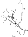
- фиг.1, в схематичном изображении вид сбоку традиционной, соответствующей уровню техники шахты моталки;- figure 1, in a schematic representation of a side view of a traditional, corresponding to the prior art mine winder;
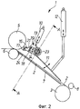
- фиг.2, в схематичном изображении вид сбоку шахты моталки с поворачивающимся сверху в металлическую полосу механизмом измерения ее натяжения, одновременно выполняющим функцию переводного распределительного устройства для полосы и находящимся в приподнятом над полосой нерабочем положении;- figure 2, in a schematic view, a side view of the winder shaft with a mechanism for measuring its tension, rotating at the top into a metal strip, simultaneously performing the function of a transfer switchgear for the strip and in an inoperative position raised above the strip;
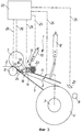
- фиг.3, объект фиг.2 с повернутым в измерительное или рабочее положение механизмом измерения натяжения незадолго до окончания процесса намотки;- figure 3, the object of figure 2 with the tension measuring mechanism turned to the measuring or working position shortly before the end of the winding process;
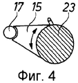
- фиг.4, фрагмент разреза через установленный в механизме измерения натяжения ролик переводного устройства.- figure 4, a fragment of a section through the roller of the transfer device installed in the tension measuring mechanism.
Шахта 1 моталки, показанная на фиг.1 в традиционном выполнении, примыкает к прокатному стану или к группе ступенчато расположенных клетей чистового стана для намотки прокатанной металлической полосы 2 на оправку 3 в бухту или рулон 4 (см. фиг.3). Полоса подается к оправке 3 подающим механизмом, от которого здесь показаны только верхний и нижний подающие ролики 5, 6. От нижнего ролика 6 до оправки 3 снизу к полосе примыкает стол 7. Начало или конец подаваемой таким образом полосы принимается первым, взаимодействующим с оправкой 3 нажимным роликом 8 или несколькими такими роликами, распределенными по окружности.The
Над металлической полосой находится переводное устройство 9, которое в позиции ожидания прилегает к подающему ролику 5. Переводное устройство 9 поворачивается цилиндром 10, который своим штоком воздействует на поворотный рычаг переводного устройства 9. Шахта 1 моталки закрыта сверху крышкой 11, проходящей от переводного устройства 9 до оправки 3. Для поворота крышки 11 к ней присоединен цилиндр 12.Above the metal strip is a transfer device 9, which is in the standby position adjacent to the
В примере выполнения шахты 1 моталки, представленном на фиг.2, 3, совпадающие с описанным выше вариантом шахты детали отмечены теми же ссылочными цифрами. Важным отличием здесь является то, что механизм 13 измерения натяжения полосы одновременно выполняет функцию переводного устройства для полосы. Этот механизм состоит из расположенного сзади или со стороны привода поворотного рычага 14 и переднего рычага 14, из которых на фиг.2 показан только первый. Оба рычага 14 связаны между собой воспринимающим скручивающие нагрузки корпусом 15 переводного устройства (см. фиг.4). Кроме того, он имеет рычаг 16 ролика, на переднем конце которого находится приводной ролик 17. Рычаг 16 поворачивается в шарнире 18. Чтобы устранить опрокидывание под действием силы тяжести, рычаг 16 удерживается в позиции элементом 19.In the exemplary embodiment of the
Как только механизм 13 измерения натяжения повернется сверху на металлическую полосу 2 и вдавится в нее своим роликом 17 с образованием угла обхвата, через ролик 17 начинает действовать сила, которая нагружает рычаг 16 по часовой стрелке. Повороту рычага в этом направлении, однако, препятствует удерживающий элемент 19, выполненный в виде динамометра 20, который скорее обеспечивает опору для рычага 16, определяет производимую опорой в оси 21 силу и как измерительный сигнал передает ее в регулятор 22 подающего устройства (см. фиг.3). Подающее устройство по результатам измерений может, например, благодаря повороту верхнего и/или нижнего ролика 5, 6 или параллельному повороту обоих роликов, или заданию различных замыкающих усилий на сторону привода и управления, обеспечивать получение на оправке 3 рулона 4 с прямыми кромками.As soon as the
Механизм 13 измерения натяжения на своем заднем по направлению движения полосы, удаленном от ролика 17 конце снабжен предусмотренным на его оси вращения роликом 23 переводного устройства, как показано на фиг. 2, 3 в виде поперечного сечения в области поворотного рычага 14 через цапфу ролика 23. Здесь шахта 1 моталки тоже сверху закрыта поворачивающейся цилиндром 12 крышкой 11. Направляющий металлическую полосу 2 стол 7, проходящий от нижнего ролика 6 до оправки 3, по меньшей мере, на своем переднем конце имеет поворотный стол 24, перемещаемый вокруг оси нижнего ролика 6 подающего устройства против часовой стрелки.The
Фиг.3, которая показывает рабочее положение незадолго до конца процесса намотки рулона 4 из металлической полосы 2, позволяет видеть, с одной стороны, угол обхвата, который полоса 2 образует вследствие вдавливания в нее ролика 17 механизма 13 измерения натяжения. С другой стороны, штриховые линии показывают различные измерительные или управляющие сигналы 25, 26, которые вводятся в регулятор 22 или выходят из него к средствам поворота верхнего и нижнего роликов 5, 6 (см. штриховые линии 26). Важные для определения и при необходимости удержания постоянным оптимального угла обхвата во время всего процесса намотки параметры задаются, например, измерением хода качающегося цилиндра или хода качающихся цилиндров 10 механизма 13 измерения натяжения, причем цилиндр/цилиндры оснащены измерителями перемещений, а также измерениями углов поворота механизма 13 и мгновенного диаметра рулона 4. Этот диаметр может быть рассчитан по замеренному числу оборотов оправки 3 (см. исходящую от него штриховую линию 25) и толщине полосы. Дополнительно возможно непосредственное измерение диаметра рулона 4 с помощью лазерно-оптического средства 27.Figure 3, which shows the working position shortly before the end of the winding process of the roll 4 from the
В любом случае возможно иметь в распоряжении для регулирования подающего устройства измерительный сигнал в виде результата измерения натяжения полосы. Альтернативой в описанном исполнении могут быть сочетания «механизм измерения натяжения полосы - переводное устройство для полосы» или «механизм - крышка шахты». Показанный на фиг.2, 3 механизм 13 своим направленным от оправки 3 роликом 17 мог бы быть интегрирован в крышку шахты, что отражено линией А-А на фиг.2. Свободное пространство от переднего ролика 5 до механизма 13 могло бы тогда (при этой опции) заполняться или перекрываться обычным переводным устройством 9 для полосы (см. фиг.1).In any case, it is possible to have a measuring signal in the form of the result of measuring the tension of the strip for controlling the feeding device. An alternative in the described embodiment may be the combination of “a mechanism for measuring the tension of the strip - transfer device for the strip” or “mechanism - the cover of the shaft. The
ВЕДОМОСТЬ ОСНОВНЫХ ПОЗИЦИЙLIST OF MAIN POSITIONS
1 - шахта моталки1 - winder shaft
2 - металлическая полоса2 - metal strip
3 - намоточная оправка3 - winding mandrel
4 - бухта/рулон4 - bay / roll
5 - верхний подающий ролик5 - upper feed roller
6 - нижний подающий ролик6 - lower feed roller
7 - стол (направляющий стол)7 - table (guide table)
8 - нажимной ролик8 - pressure roller
9 - переводное устройство для полосы9 - transfer device for the strip
10 - цилиндр10 - cylinder
11 - крышка шахты11 - shaft cover
12 - цилиндр12 - cylinder
13 - механизм измерения натяжения полосы13 - strip tension measuring mechanism
14 - поворотный рычаг14 - rotary lever
15 - корпус переводного устройства15 - housing transfer device
16 - рычаг ролика16 - roller lever
17 - ролик17 - roller
18 - шарнир18 - hinge
19 - удерживающий элемент19 - holding element
20 - динамометр20 - dynamometer
21 - ось динамометра21 - axis of the dynamometer
22 - регулятор подающего устройства22 - feed controller
23 - ролик переводного устройства23 - roller transfer device
24 - поворотный стол24 - rotary table
25 - измерительный сигнал25 - measuring signal
26 - измерительный сигнал26 - measuring signal
27 - лазерно-оптическое измерительное средство27 - laser-optical measuring tool
Claims (12)
Applications Claiming Priority (4)
| Application Number | Priority Date | Filing Date | Title |
|---|---|---|---|
| DE102006045608 | 2006-09-25 | ||
| DE102006045608.4 | 2006-09-25 | ||
| DE102007045425.4 | 2007-09-21 | ||
| DE102007045425A DE102007045425A1 (en) | 2006-09-25 | 2007-09-21 | Method and device for winding metal strips on a winding mandrel |
Publications (1)
| Publication Number | Publication Date |
|---|---|
| RU2391167C1 true RU2391167C1 (en) | 2010-06-10 |
Family
ID=39185155
Family Applications (1)
| Application Number | Title | Priority Date | Filing Date |
|---|---|---|---|
| RU2009115695/02A RU2391167C1 (en) | 2006-09-25 | 2007-09-21 | Method and device for winding metal strips onto holder |
Country Status (10)
| Country | Link |
|---|---|
| US (1) | US20100025514A1 (en) |
| EP (1) | EP2109510B1 (en) |
| JP (1) | JP2010504216A (en) |
| KR (1) | KR101071117B1 (en) |
| CN (1) | CN101516539B (en) |
| BR (1) | BRPI0716770B1 (en) |
| CA (1) | CA2664263C (en) |
| DE (1) | DE102007045425A1 (en) |
| RU (1) | RU2391167C1 (en) |
| WO (1) | WO2008037395A1 (en) |
Families Citing this family (13)
| Publication number | Priority date | Publication date | Assignee | Title |
|---|---|---|---|---|
| DE102009058875A1 (en) * | 2009-12-18 | 2011-07-07 | SMS Siemag AG, 40237 | A reel device and method for operating a reel device |
| KR101421814B1 (en) * | 2012-11-02 | 2014-07-22 | 주식회사 포스코 | Guiding apparatus for winding strip |
| DE102012224351A1 (en) | 2012-12-21 | 2014-06-26 | Sms Siemag Ag | Method and device for winding a metal strip |
| US9908137B2 (en) | 2013-11-14 | 2018-03-06 | Illinois Tool Works Inc. | Fluid application device having a modular non-contact nozzle for applying fluid to an article |
| US9718083B2 (en) | 2013-11-14 | 2017-08-01 | Illinois Tool Works Inc. | Fluid application device having a modular nozzle assembly for applying fluid to an article |
| US9932704B2 (en) * | 2013-11-22 | 2018-04-03 | Illinois Tool Works Inc. | Fluid application device, strand engagement device and method of controlling the same |
| CN103743953B (en) * | 2013-12-29 | 2017-01-04 | 中国计量学院 | Twin metal strip resistance servo-actuated synchronization continuous measurement system |
| MX2016006380A (en) * | 2015-05-18 | 2016-11-17 | Danieli Off Mecc | Tensioning unit for a rolling apparatus. |
| PL226814B1 (en) * | 2015-05-29 | 2017-09-29 | Przedsiębiorstwo Concept Stal B&S Lejman Spółka Jawna | Sheet rolling machine |
| CN107774728A (en) * | 2016-08-31 | 2018-03-09 | 扬中凯悦铜材有限公司 | Copper bar drawing winds integrated apparatus |
| CN109650123A (en) * | 2019-02-27 | 2019-04-19 | 中冶赛迪工程技术股份有限公司 | A kind of strip tape threading apparatus and method |
| CA3168206A1 (en) * | 2020-01-22 | 2021-07-29 | Novelis Inc. | Sensing and offsetting the force of events in a coil forming operation |
| EP4019158B1 (en) * | 2020-12-23 | 2023-11-01 | Primetals Technologies Austria GmbH | Reel device for large thickness range of metal strips |
Family Cites Families (20)
| Publication number | Priority date | Publication date | Assignee | Title |
|---|---|---|---|---|
| JPS51127988A (en) * | 1975-04-30 | 1976-11-08 | Ishikawajima Harima Heavy Ind Co Ltd | Tension control device having looper and this looper |
| JPS5865674A (en) * | 1981-10-16 | 1983-04-19 | Ricoh Co Ltd | Printer |
| JPS60231516A (en) | 1984-04-28 | 1985-11-18 | Sumitomo Metal Ind Ltd | Coiler having looper mechanism |
| DE3507251A1 (en) * | 1985-03-01 | 1986-09-04 | SMS Schloemann-Siemag AG, 4000 Düsseldorf | DRIVER FOR ROLLER TAPE |
| GB8608494D0 (en) * | 1986-04-08 | 1986-05-14 | Davy Mckee Sheffield | Strip guiding for downcoilers |
| JPH01109314U (en) * | 1988-01-20 | 1989-07-24 | ||
| SE461298B (en) * | 1988-06-02 | 1990-01-29 | Asea Brown Boveri | PLANET METERS FOR ROLLED BANDS |
| CN2198987Y (en) * | 1994-08-23 | 1995-05-31 | 陈平 | Band coiling device for steel band-coiled type pressure container |
| DE19520709A1 (en) * | 1995-06-09 | 1996-12-12 | Schloemann Siemag Ag | Drivers for rolled strips |
| JPH10137846A (en) * | 1996-11-06 | 1998-05-26 | Mitsubishi Heavy Ind Ltd | Band steel coiler for hot rolling equipment |
| DE19704447A1 (en) * | 1997-02-06 | 1998-08-13 | Schloemann Siemag Ag | Flatness measuring roller |
| DE19818207C2 (en) * | 1998-04-23 | 2000-05-31 | Schloemann Siemag Ag | Steckel hot rolling mill |
| US6039283A (en) * | 1998-05-19 | 2000-03-21 | Hylsa S.A. De C.V. | Thin strip coiling system |
| US6146411A (en) * | 1998-12-24 | 2000-11-14 | Alsius Corporation | Cooling system for indwelling heat exchange catheter |
| US6321052B1 (en) * | 1999-09-08 | 2001-11-20 | Fuji Xerox Co., Ltd. | Method and apparatus for correcting running state and tension for an endless belt in an image-forming apparatus |
| DE19953524A1 (en) * | 1999-11-05 | 2001-05-10 | Sms Demag Ag | Loop lifter |
| US6722087B1 (en) * | 2000-09-21 | 2004-04-20 | Mic Industries | Building panel and panel crimping machine |
| DE10131850B4 (en) * | 2001-06-30 | 2013-04-25 | Sms Siemag Aktiengesellschaft | Thin strip reel with flatness measuring roll |
| FI114391B (en) * | 2002-04-30 | 2004-10-15 | Pesmel Oy | Wrapping and diaphragm wrapping apparatus comprising a circumferential structure |
| DE10258499A1 (en) * | 2002-12-14 | 2004-07-01 | Sms Demag Ag | Deflection device of a reel system for reeling tapes |
-
2007
- 2007-09-21 BR BRPI0716770-9A patent/BRPI0716770B1/en active IP Right Grant
- 2007-09-21 US US12/442,715 patent/US20100025514A1/en not_active Abandoned
- 2007-09-21 CA CA2664263A patent/CA2664263C/en not_active Expired - Fee Related
- 2007-09-21 CN CN2007800356368A patent/CN101516539B/en active Active
- 2007-09-21 JP JP2009528648A patent/JP2010504216A/en active Pending
- 2007-09-21 WO PCT/EP2007/008217 patent/WO2008037395A1/en active Application Filing
- 2007-09-21 KR KR1020097003037A patent/KR101071117B1/en active IP Right Grant
- 2007-09-21 DE DE102007045425A patent/DE102007045425A1/en not_active Withdrawn
- 2007-09-21 RU RU2009115695/02A patent/RU2391167C1/en active
- 2007-09-21 EP EP07818307.6A patent/EP2109510B1/en active Active
Also Published As
| Publication number | Publication date |
|---|---|
| BRPI0716770B1 (en) | 2019-03-26 |
| CN101516539A (en) | 2009-08-26 |
| EP2109510A1 (en) | 2009-10-21 |
| US20100025514A1 (en) | 2010-02-04 |
| BRPI0716770A2 (en) | 2013-09-17 |
| EP2109510B1 (en) | 2014-02-12 |
| WO2008037395A1 (en) | 2008-04-03 |
| JP2010504216A (en) | 2010-02-12 |
| CA2664263C (en) | 2011-04-19 |
| CN101516539B (en) | 2012-02-15 |
| CA2664263A1 (en) | 2008-04-03 |
| KR101071117B1 (en) | 2011-10-07 |
| DE102007045425A1 (en) | 2008-04-17 |
| KR20090031622A (en) | 2009-03-26 |
Similar Documents
| Publication | Publication Date | Title |
|---|---|---|
| RU2391167C1 (en) | Method and device for winding metal strips onto holder | |
| RU2391169C1 (en) | Method and device of metal band winding onto coiling mandrel | |
| JP2010504216A5 (en) | ||
| US5611500A (en) | Reel wound roll load sensing arrangement | |
| KR100202809B1 (en) | Arrangement in a coil winding machine for a cable or a similar strandlie product | |
| US2984429A (en) | Single rollstand web handling machine | |
| US3546067A (en) | Apparatus for breaking the curl in traveling material webs formed of paper,cardboard or the like | |
| RU2442671C2 (en) | Furnace coiler | |
| NO316219B1 (en) | Procedure for rewinding a paper web | |
| CN206241150U (en) | A kind of bar straightener with detection function | |
| CN107555256A (en) | A kind of fabric tension control device | |
| JPH0756083Y2 (en) | Exit guide position controller | |
| WO2008122342A1 (en) | Dual pivot ironing roll | |
| RU2820556C1 (en) | Torsion guide, guide device and corresponding method of use | |
| US5441213A (en) | Diameter feedback controlled winding device | |
| JP3590657B2 (en) | Roll bending equipment | |
| RU2254951C1 (en) | Coiled material centering apparatus | |
| KR20060021190A (en) | Device for bending and guiding top of strip in coiler | |
| CN113348042B (en) | Steering winch and method for operating a steering winch | |
| JPS6142642Y2 (en) | ||
| SU1186311A1 (en) | Tensioning apparatus | |
| KR101406596B1 (en) | Lateral Moving Strip Sensing Device of Hot Rolling Apparatus | |
| JP4491470B2 (en) | Method of measuring tension using tension measuring device attached to skin pass mill | |
| RU2210450C1 (en) | Apparatus for centering coiled material | |
| JPS6264419A (en) | Rolling line for rolling tubular or cylindrical material to be rolled |