RU2388572C2 - Continuous casting unit for billets or blooms - Google Patents
Continuous casting unit for billets or blooms Download PDFInfo
- Publication number
- RU2388572C2 RU2388572C2 RU2007128951/02A RU2007128951A RU2388572C2 RU 2388572 C2 RU2388572 C2 RU 2388572C2 RU 2007128951/02 A RU2007128951/02 A RU 2007128951/02A RU 2007128951 A RU2007128951 A RU 2007128951A RU 2388572 C2 RU2388572 C2 RU 2388572C2
- Authority
- RU
- Russia
- Prior art keywords
- workpiece
- mold
- length
- smooth transitions
- section
- Prior art date
Links
Images


Classifications
-
- B—PERFORMING OPERATIONS; TRANSPORTING
- B22—CASTING; POWDER METALLURGY
- B22D—CASTING OF METALS; CASTING OF OTHER SUBSTANCES BY THE SAME PROCESSES OR DEVICES
- B22D11/00—Continuous casting of metals, i.e. casting in indefinite lengths
- B22D11/04—Continuous casting of metals, i.e. casting in indefinite lengths into open-ended moulds
- B22D11/041—Continuous casting of metals, i.e. casting in indefinite lengths into open-ended moulds for vertical casting
-
- B—PERFORMING OPERATIONS; TRANSPORTING
- B22—CASTING; POWDER METALLURGY
- B22D—CASTING OF METALS; CASTING OF OTHER SUBSTANCES BY THE SAME PROCESSES OR DEVICES
- B22D11/00—Continuous casting of metals, i.e. casting in indefinite lengths
- B22D11/12—Accessories for subsequent treating or working cast stock in situ
- B22D11/128—Accessories for subsequent treating or working cast stock in situ for removing
Landscapes
- Engineering & Computer Science (AREA)
- Mechanical Engineering (AREA)
- Continuous Casting (AREA)
- Treatment Of Steel In Its Molten State (AREA)
- Metal Rolling (AREA)
- Forging (AREA)
Abstract
Description
Изобретение относится к установке непрерывной разливки для сортовых или блюмовых заготовок согласно ограничительной части п.1 формулы изобретения.The invention relates to a continuous casting plant for varietal or bloom blanks according to the preamble of claim 1.
Непрерывнолитые длинные заготовки разливаются преимущественно в гильзовый кристаллизатор с прямоугольным, в частности близким к квадрату, или круглым поперечным сечением. Сортовые или блюмовые заготовки затем обрабатываются прокаткой или ковкой.Continuously cast long billets are poured mainly into a shell mold with a rectangular, in particular close to square, or round cross-section. Varietal or bloom blanks are then processed by rolling or forging.
Для изготовления непрерывнолитых изделий с высоким качеством поверхности и подходящей структурой, в частности сортовых или блюмовых удлиненных заготовок, решающее значение имеет равномерный теплоотвод по внешнему периметру поперечного сечения заготовки между образующейся заготовкой и поверхностью полости формы. Известно много решений, предусматривающих специальную геометрию полости формы, в частности в области угловых закругленных переходов, при которой между образующейся корочкой заготовки и стенкой кристаллизатора не образуется нежелательный воздушный зазор, вызывающий неравномерный теплоотвод по периметру поверхности в поперечном сечении заготовки, дефекты кристаллизации и прорывы металла.For the manufacture of continuously cast products with a high surface quality and a suitable structure, in particular long or bloom elongated workpieces, uniform heat dissipation along the external perimeter of the cross section of the workpiece between the formed workpiece and the surface of the mold cavity is crucial. Many solutions are known that provide for a special geometry of the mold cavity, in particular in the area of rounded angular transitions, in which an undesirable air gap does not form between the crust of the preform and the wall of the mold, causing uneven heat removal along the surface perimeter in the cross section of the preform, crystallization defects and metal breakouts.
Углы полости формы гильзового кристаллизатора скруглены посредством плавных переходов. Чем большими выполнены такие плавные переходы в полости формы кристаллизатора, тем сложнее достигается равномерный отвод тепла между образующейся корочкой заготовки и стенками кристаллизатора, в частности по поверхности полости формы. Начальная кристаллизация заготовки чуть ниже зеркала расплава в кристаллизаторе происходит различно на прямых участках полости формы и в областях скруглений. Тепловой поток на прямых или по существу прямых участках является квазиодномерным и описывается как тепловой поток через плоскую стенку. В противоположность этому, тепловой поток на скругленных угловых участках является двухмерным и описывается как тепловой поток через искривленную стенку.The corners of the mold cavity of the shell mold are rounded by smooth transitions. The larger such smooth transitions are made in the mold cavity, the more difficult it is to achieve uniform heat dissipation between the formed workpiece crust and the mold walls, in particular along the surface of the mold cavity. The initial crystallization of the workpiece just below the melt mirror in the mold occurs differently in the straight sections of the mold cavity and in the fillet regions. The heat flux in straight or substantially straight sections is quasi-one-dimensional and is described as heat flux through a flat wall. In contrast, the heat flux in the rounded corner sections is two-dimensional and is described as heat flux through a curved wall.
Образующаяся корочка заготовки, как правило в угловых областях, в начале кристаллизации под зеркалом расплава является более толстой, чем на прямых участках, и возникает раньше по времени и более интенсивно. Это приводит к тому, что уже через 2 секунды корочка заготовки в угловых областях неравномерно отдаляется от стенки кристаллизатора и образуется воздушный зазор, который значительно снижает тепловой поток. Это снижение теплового потока усложняет не только дальнейший рост корочки, но и может привести к расплавлению уже закристаллизовавшихся внутренних участков корочки заготовки. Подобные «качели» в тепловом потоке (охлаждение и повторный нагрев) ведут к дефектам литья, таким как поверхностные и продольные трещины на кромках или в близких к кромкам областях, к отклонениям от заданной формы, таким как ромбичность, втягивания и т.д. Повторное плавление корочки заготовки или значительные продольные трещины могут также приводить к прорывам металла.The formed crust of the workpiece, as a rule in the corner regions, at the beginning of crystallization under the melt mirror is thicker than in straight sections, and occurs earlier in time and more intensively. This leads to the fact that after 2 seconds the billet crust in the corner regions unevenly moves away from the mold wall and an air gap forms, which significantly reduces the heat flux. This decrease in heat flux complicates not only the further growth of the crust, but can also lead to the melting of the already crystallized inner sections of the crust of the workpiece. Such “swings” in the heat flux (cooling and reheating) lead to casting defects, such as surface and longitudinal cracks at the edges or in areas close to the edges, to deviations from a given shape, such as rhombicity, retraction, etc. Re-melting the workpiece crust or significant longitudinal cracks can also lead to breakthroughs of the metal.
Чем больше размер скруглений по отношению к боковой стороне сечения заготовки, в частности, если скругления составляют 10% и более от длины боковой стороны сечения полости формы, тем чаще возникают подобные дефекты. Это является причиной того, что радиус скруглений ограничивают обычно 5-8 мм, хотя для последующей прокатки было бы предпочтительным большее закругление.The larger the fillet size with respect to the side of the cross section of the workpiece, in particular if the fillets are 10% or more of the length of the side of the cross section of the mold cavity, the more often such defects occur. This is the reason that the radius of the fillets is usually limited to 5-8 mm, although a larger fillet would be preferable for subsequent rolling.
При разливке с высокой скоростью снижается время пребывания отливаемой заготовки в полости кристаллизатора, и корочка имеет меньше времени на рост. В зависимости от выбранного формата отливаемой заготовки необходимо, чтобы заготовка непосредственно после выхода из кристаллизатора поддерживалась поддерживающими роликами для предотвращения выпучивания корочки заготовки и возможных прорывов. Подобные поддерживающие клети непосредственно под кристаллизатором подвергаются сильному износу и после прорыва могут быть снова приведены в действие только по истечении значительного времени и при высоких затратах.When casting at high speed, the residence time of the cast billet in the mold cavity is reduced, and the crust has less time to grow. Depending on the selected format of the cast billet, it is necessary that the billet immediately after leaving the mold is supported by supporting rollers to prevent buckling of the billet crust and possible breakthroughs. Such support stands directly under the mold undergo severe wear and can only be reactivated after a breakthrough after a considerable time and at high cost.
Из документа JP-A-11 151555 известен кристаллизатор для непрерывной разливки сортовых или блюмовых заготовок. Для повышения скорости разливки и предотвращения возникновения ромбичности прямоугольных заготовок на четырех углах полости формы выполнены скругления в виде так называемых угловых охлаждающих частей. На стороне подачи расплава угловые охлаждающие части выполнены в виде круговых выемок в стенке кристаллизатора, которые уменьшаются в направлении движения заготовки, и на стороне выхода из кристаллизатора остаются только угловые скругления. Степень кривизны круговых выемок увеличивается в направлении движения заготовок к выходу из кристаллизатора. Придание подобной формы обеспечивает непрерывный контакт между угловыми частями корочки и специально сформированными угловыми охлаждающими частями кристаллизатора.From JP-A-11 151555, a mold is known for the continuous casting of high-quality or bloom blanks. To increase the casting speed and prevent the occurrence of rhombic rectangular workpieces at the four corners of the mold cavity, fillets were made in the form of so-called angular cooling parts. On the melt supply side, the angular cooling portions are made in the form of circular recesses in the mold wall, which decrease in the direction of movement of the workpiece, and only angular fillets remain on the exit side of the mold. The degree of curvature of the circular grooves increases in the direction of movement of the workpieces to the exit of the mold. Giving a similar shape provides continuous contact between the corner parts of the crust and specially formed corner cooling parts of the mold.
Из документа JP-A-09262641 известен гильзовый кристаллизатор для непрерывной разливки прямоугольных заготовок, в котором для предотвращения возникновения продольных трещин на кромках заготовки и ромбичности поперечного сечения заготовки в полости формы предусмотрены скругления с различными угловыми радиусами на верхнем и нижнем концах кристаллизатора. Угловой радиус на стороне подачи расплава в кристаллизатор выбирается меньшим, чем угловой радиус на стороне выхода из кристаллизатора. За счет этого мероприятия предотвращается возникновение воздушного зазора между корочкой заготовки и стенкой кристаллизатора. Объяснение размеров скругления относительно длины боковой стороны в поперечном сечении заготовки и абсолютной величины поперечного сечения, а также объяснение упрощения следующих за кристаллизатором поддерживающих направляющих средств не предоставляются и не обозначены.From the document JP-A-09262641 there is known a shell mold for continuous casting of rectangular billets, in which roundings with different angular radii at the upper and lower ends of the mold are provided to prevent longitudinal cracks at the edges of the workpiece and the rhombic cross section of the workpiece in the mold cavity. The angular radius on the supply side of the melt into the mold is selected smaller than the angular radius on the exit side of the mold. Due to this measure, the occurrence of an air gap between the workpiece crust and the mold wall is prevented. An explanation of the rounding dimensions relative to the side length in the cross section of the workpiece and the absolute value of the cross section, as well as an explanation of the simplification of the supporting guide means following the mold, are not provided and are not indicated.
В основе изобретения лежит задача создания установки непрерывной разливки для сортовых или блюмовых заготовок, преимущественно с по существу прямоугольным или близким к нему сечением, в которой в комбинации реализуются указанные цели. Должна обеспечиваться высокая производительность разливки при максимально малом количестве ручьев, высоком качестве отливаемой заготовки и при минимальных затратах на строительство и на эксплуатацию. Улучшение качества заготовки предусматривает, в частности, устранение дефектов литья в угловых зонах, таких как трещины, дефекты кристаллизации и загрязнения корочки литейным порошком, а также избежание отклонений по массе, таких как ромбичность, выпуклости или вогнутости. Установка непрерывной разливки согласно изобретению, кроме того, далее снижает инвестиционные и эксплуатационные затраты на опорные-направляющие клети, а также обеспечивает повышение экономичности и качество при изготовлении заготовки путем использования устройства перемешивания в кристаллизаторе.The basis of the invention is the task of creating a continuous casting plant for high-quality or bloom blanks, mainly with a substantially rectangular or close to it section in which these goals are realized in combination. High casting productivity should be ensured with the smallest number of streams, high quality of the cast billet, and with minimal construction and operation costs. Improving the quality of the workpiece includes, in particular, eliminating casting defects in corner zones, such as cracks, crystallization defects and contamination of the crust by casting powder, as well as avoiding mass deviations, such as rhombicity, convexity or concavity. The continuous casting plant according to the invention, in addition, further reduces the investment and operating costs of the support-guide stands, and also provides increased efficiency and quality in the manufacture of the workpiece by using a mixing device in the mold.
Согласно изобретению поставленные цели достигаются признаками пункта 1 формулы изобретения.According to the invention, the goals are achieved by the features of paragraph 1 of the claims.
Посредством установки непрерывной разливки согласно изобретению возможно отливать массивные сортовые или блюмовые заготовки, а также профильные заготовки с высокими скоростями и при отсутствии или с наличием опорной направляющей, с соответствующей длиной и/или шириной опоры непосредственно под кристаллизатором. При заданной производительности за счет этого могут снижаться число ручьев и инвестиционные затраты. Также за счет меньшего числа ручьев и отсутствия или снижения опорных направляющих для отлитой заготовки одновременно уменьшаются затраты на содержание установки. За счет увеличения скруглений на кромках отлитой заготовки можно значительно снизить критические давления в остальной плоской корочке на выходе из кристаллизатора, которые вызываются ферростатическим давлением жидкой сердцевины. Сокращение длины расположенных между скругленными угловыми участками ровных участков полости формы на, например, 10% ведет к снижению изгибающего напряжения на этих участках, вызывающего выпучивание, примерно на 20%.By installing a continuous casting according to the invention, it is possible to cast massive varietal or bloom blanks, as well as profiled blanks with high speeds and in the absence or presence of a support guide, with an appropriate length and / or width of the support directly under the mold. At a given productivity, the number of streams and investment costs can be reduced due to this. Also, due to the smaller number of streams and the absence or reduction of support rails for the cast billet, the costs of maintaining the installation are simultaneously reduced. By increasing the rounding at the edges of the cast billet, it is possible to significantly reduce the critical pressures in the remaining flat crust at the exit from the mold, which are caused by the ferrostatic pressure of the liquid core. Reducing the length of even sections of the mold cavity located between the rounded corner portions by, for example, 10% leads to a decrease in bending stress in these areas, causing buckling, by about 20%.
Помимо этих экономических преимуществ по многим аспектам улучшается и качество заготовки. За счет регулирования целенаправленно уменьшаемого зазора между корочкой заготовки и стенкой кристаллизатора или путем целенаправленного деформирования корочки заготовки в областях скруглений выравнивается рост корочки заготовки по периферии заготовки и по заранее определенной части длины кристаллизатора, за счет чего улучшается структура заготовки и устраняются дефекты литья на кромках, такие как трещины и т.д. Дополнительно могут устраняться или уменьшаться геометрические отклонения заготовки, например ромбичность, выпуклости и т.д. Увеличение угловых скруглений также влияет на характеристики течения в области зеркала расплава. При использовании литейного порошка для покрывания зеркала расплава и при увеличении угловых скруглений достигается выравнивание характеристик плавления литейного порошка во всем объеме мениска. Этот эффект еще более увеличивается у кристаллизатора, снабженного средствами для перемешивания. Дефекты заготовки, такие как включения литейного порошка и шлака, в частности, в угловых областях, а также дефекты поверхности заготовки снижаются за счет выравнивания характеристик плавления порошка. За счет согласования величины угловых скруглений заготовки к потребностям последующей прокатки или ковки достигаются дополнительные преимущества в качестве.In addition to these economic advantages, the quality of the workpiece is improved in many aspects. By adjusting the deliberately reduced gap between the workpiece crust and the mold wall, or by deliberately deforming the workpiece crust in the fillet regions, the growth of the workpiece crust is evened out along the periphery of the workpiece and a predetermined part of the mold length, thereby improving the workpiece structure and eliminating casting defects at the edges, such like cracks etc. Additionally, geometrical deviations of the workpiece, such as rhombicity, bulges, etc., can be eliminated or reduced. An increase in the angular rounding also affects the flow characteristics in the region of the melt mirror. When using casting powder to cover the melt mirror and increasing the angular rounding, equalization of the melting characteristics of the casting powder in the entire meniscus is achieved. This effect is further enhanced in a mold equipped with stirring means. Defects in the workpiece, such as inclusions of foundry powder and slag, in particular in the corner regions, as well as defects in the surface of the workpiece are reduced by equalizing the melting characteristics of the powder. By coordinating the values of the angular rounding of the workpiece to the needs of subsequent rolling or forging, additional quality advantages are achieved.
Граница между применением безопорного направления заготовки в зоне вторичного охлаждения (ЗВО) и сниженного по длине или по ширине опорного направления зависит от множества параметров, в частности от характеристик выпучивания отлитой заготовки. Помимо основных параметров величина формата и общая длина скруглений плавных переходов, относящихся к одной стороне заготовки, или длина ровного участка между двумя скруглениями, относящимися к одной стороне заготовки, зависят от скорости разливки, длины полости формы, температуры стали и ее химического состава. При экспериментах по определению границы между применением безопорного выполнения ЗВО и сниженной опоры заготовки в ЗВО рекомендуются следующее значения. При размерах заготовки, меньших, чем 150×150 мм2, и общей длине двух скруглений на одной стороне заготовки от примерно 70% и более размера стороны заготовки может осуществляться безопорное направление. При размерах заготовки более чем 150×150 мм2 и общей длине прямого участка между двумя скруглениями на одной стороне заготовки от примерно 30% и более размера стороны заготовки может осуществляться сниженное по длине и/или ширине опорное направление заготовки. В подходе, предложенном в изобретении, можно осуществлять влияние на характеристики вспучивания заготовки после выхода из кристаллизатора, во-первых, путем увеличения скруглений, например, до 100% длины боковой стороны поперечного сечения заготовки, а с другой стороны, путем изменения степени искривления следующих в направлении движения заготовки скруглений, при этом по сравнению с уровнем техники обеспечиваются существенно большие форматы заготовки также при высоких скоростях разливки при безопорном направлении заготовки или при сниженном опорном направлении заготовки.The border between the application of the unsupported direction of the workpiece in the secondary cooling zone (ZVO) and the reduced direction along the length or width of the support direction depends on many parameters, in particular, on the characteristics of the buckling of the cast workpiece. In addition to the main parameters, the size of the format and the total length of the fillets of smooth transitions related to one side of the workpiece, or the length of an even section between two fillets belonging to one side of the workpiece, depends on the casting speed, the length of the mold cavity, the temperature of the steel and its chemical composition. When experimenting to determine the boundary between the use of unsupported execution of the air-conditioning device and the reduced support of the workpiece, the following values are recommended in the air-cooling device When the dimensions of the workpiece are less than 150 × 150 mm 2 and the total length of two fillets on one side of the workpiece is from about 70% or more than the size of the side of the workpiece, an unsupported direction can be carried out. When the dimensions of the workpiece are more than 150 × 150 mm 2 and the total length of the straight section between two fillets on one side of the workpiece is from about 30% or more of the side size of the workpiece, the support direction of the workpiece reduced in length and / or width can be realized. In the approach proposed in the invention, it is possible to influence the swelling characteristics of the preform after exiting the mold, firstly, by increasing fillets, for example, to 100% of the side length of the cross section of the preform, and, on the other hand, by changing the degree of curvature of the following the direction of movement of the rounding workpiece, while compared with the prior art, significantly larger workpiece formats are also provided at high casting speeds with an unsupported workpiece direction or at lower reference direction of the workpiece.
Плавные переходы на периферии поперечного сечения полости формы могут отражаться как соединенные круговые линии и т.д. Дополнительные преимущества достигаются, если плавные переходы присоединяются к прямым участкам периметра не по касательной, то есть не в точке. Согласно другому варианту может быть выбран такой характер искривления вдоль плавных переходов, который приближается и затем снова отдаляется от максимальной степени искривления 1/R. Максимальная степень искривления 1/R плавных переходов в случае перехода в направлении движения заготовки может постоянно или непостоянно снижаться. Для изготовления полостей формы при помощи режущих станков с программным управлением также является предпочтительным, если периферийные линии плавного перехода в поперечном сечении заготовки имеют характер искривления, который описывается математической функцией и который приближается и затем снова отдаляется от максимальной степени искривления 1/R, например в случае функции суперкруга или суперэллипса.Smooth transitions at the periphery of the cross-section of the mold cavity can be reflected as connected circular lines, etc. Additional benefits are achieved if smooth transitions join the straight sections of the perimeter not tangentially, that is, not at a point. According to another embodiment, such a nature of curvature along smooth transitions can be chosen that approaches and then again moves away from the maximum degree of curvature 1 / R. The maximum degree of curvature 1 / R of smooth transitions in the case of a transition in the direction of movement of the workpiece can be constantly or continuously reduced. For the manufacture of mold cavities using programmed cutting machines, it is also preferable if the peripheral smooth transition lines in the cross section of the workpiece have a curvature that is described by a mathematical function and which approaches and then again moves away from the maximum degree of curvature 1 / R, for example, in the case supercircle or superellipse functions.
Плавные переходы с размерами переходов от 25% и более длины боковой стороны поперечного сечения заготовки могут обеспечивать дополнительные преимущества, если по существу прямоугольное поперечное сечение полости формы состоит из четырех дуг, которые содержат, каждая, примерно четверть периметра поперечного сечения, и дуги описываются математической функцией. Функция ![]()
![]()
Периметр поперечного сечения заготовки может также составляться из большего числа дуг, при этом плавные переходы имеют характер изгибания, который описывается функцией, например |x|n+|y|n=|R|n. Расположенные между плавными переходами участки периметра поперечно сечения могут содержать слегка изогнутые участки дуг, как это предлагается в документе ЕР 0498296. Глядя в направлении движения заготовки, можно видеть снижение степени искривления 1/R и дуги плавного перехода, а также лежащие между ними относительно вытянутые линии дуг, при этом по меньшей мере на части длины кристаллизатора корочка заготовки при прохождении подвергается по всей поверхности легкой деформации или вытягиванию.The perimeter of the cross section of the workpiece can also be composed of a larger number of arcs, while smooth transitions have a bending character, which is described by a function, for example | x | n + | y | n = | R | n Cross-sectional sections of the perimeter between smooth transitions may contain slightly curved sections of arcs, as proposed in document EP 0498296. Looking in the direction of movement of the workpiece, you can see a decrease in the degree of curvature 1 / R and smooth transition arcs, as well as relatively elongated lines lying between them arcs, while at least part of the length of the mold, the crust of the workpiece during passage is exposed to the entire surface of light deformation or stretching.
В зависимости от выбранного разливаемого формата заготовки и предусмотренной максимальной скорости литья может устанавливаться оптимальная длина кристаллизатора. Отливаемые форматы между 120×120 мм2 и 160×160 мм2 могут оптимально отливаться при высокой скорости литья и при длине кристаллизатора примерно 1000 мм при безопорном направлении заготовки.Depending on the selected casting format of the workpiece and the provided maximum casting speed, the optimum length of the mold can be set. Cast formats between 120 × 120 mm 2 and 160 × 160 mm 2 can be optimally cast at a high casting speed and with a mold length of approximately 1000 mm with an unsupported workpiece direction.
Увеличенные угловые скругления полости формы создают не только преимущества при разливке с покрытием литейным порошком зеркала расплава. При увеличении угловых скруглений также возможно усилить перемешивание в области зеркала расплава и в жидкой ванне при остающемся постоянном устройстве электрического перемешивания. Эта возможность улучшения перемешивающего действия за счет геометрического выполнения полости формы дает дополнительную свободу и конструктивные возможности по внедрению перемешивания при отливке сортовых или блюмовых заготовок.The increased angular rounding of the mold cavity creates not only advantages when casting melt mirrors coated with casting powder. With an increase in the angular fillets, it is also possible to increase mixing in the region of the melt mirror and in the liquid bath with the remaining constant electric mixing device. This possibility of improving the mixing action due to the geometric execution of the mold cavity gives additional freedom and design possibilities for introducing mixing during casting of varietal or bloom blanks.
Далее посредством фигур поясняются примеры выполнения изобретения, при этом показано;Further, by way of figures, examples of carrying out the invention are explained, while it is shown;
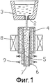
Фиг.1 - вертикальный разрез части установки непрерывной разливки.Figure 1 is a vertical section of a part of a continuous casting plant.
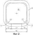
Фиг.2 - вид сверху на медную гильзу кристаллизатора для отливки блюмов.Figure 2 is a top view of a copper sleeve of the mold for casting blooms.
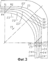
Фиг.3 - вид сверху на угловые скругления полости формы с плавными переходами.Figure 3 is a top view of the angular rounding of the mold cavity with smooth transitions.
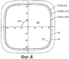
Фиг.4 - вид сверху медной гильзы с периметром последующих поперечных сечений полостей формы.Figure 4 is a top view of a copper sleeve with a perimeter of subsequent cross sections of the mold cavities.
Фиг.5 - вид сверху медной гильзы с периметром других поперечных сечений полостей формы.Figure 5 is a top view of a copper sleeve with the perimeter of other cross sections of the mold cavities.
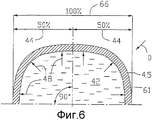
Фиг.6 - горизонтальный разрез через половину ручья в ЗВО.6 is a horizontal section through half a stream in the ZVO.
Фиг.7 - горизонтальный разрез другого примера через половину ручья в ЗВО.Fig. 7 is a horizontal section through another example through a half stream in the ZVO.
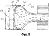
Фиг.8 - горизонтальный разрез половины профильной заготовки в ЗВО.Fig. 8 is a horizontal section through half of a profile blank in a ZVO.
На фиг.1 показано, что через сливной стакан 2 промежуточной емкости 3 жидкая сталь поступает вертикально в кристаллизатор 4. Кристаллизатор 4 имеет прямоугольную полость формы для разливки блюмовой заготовки, например 120×120 мм2. Позицией 5 показана частично затвердевшая заготовка с корочкой 6 и жидкой сердцевиной 7. Вне кристаллизатора 4 схематично показано устройство 8 электромагнитного перемешивания, выполненное с возможностью перемещения по высоте. Оно может также быть расположено внутри конструкции кристаллизатора 4, например в водяной рубашке. Устройство 8 перемешивания создает горизонтально циркулирующее вращательное движение в области зеркала ванны и в жидкой ванне. Непосредственно к кристаллизатору 4 примыкает безопорная первая ЗВО, снабженная распылительными форсунками 9.Figure 1 shows that through the drain cup 2 of the
На фиг.2 позицией 10 показана полость формы гильзового кристаллизатора 11 с плавными переходами 12, 12', 13, 13' в угловых областях. Скругления 14, 15 плавных переходов 12, 12', 13, 13' составляют в данном примере, каждый, примерно 20% длины 16 стороны поперечного сечения заготовки. Степень искривления 1/R плавных переходов 12, 13, расположенных на стороне подачи расплава, отличается от степени искривления 1/R плавных переходов 12', 13', расположенных на стороне выхода из кристаллизатора. По меньшей мере на части длины кристаллизатора уменьшается степень искривления 1/R плавных переходов 12, 13 от, например, 1/R=0,05 до степени искривления 1/R=0,046 у плавных переходов 12', 13'. Посредством выбора величины снижения степени искривления может целенаправленно регулироваться увеличение зазора между образующейся корочкой заготовки и полостью формы или целенаправленная деформация корочки заготовки и, таким образом, тепловой поток между корочкой заготовки и полостью формы. Помимо повышенного и, рассматривая по периметру, выровненного теплового потока величина скруглений 14, 15 также обеспечивает то, что частично затвердевшая заготовка после выхода из полости формы, не смотря на высокую скорость литья, может направляться через ЗВО с применением безопорного направления или сниженного опорного направления. При заранее заданном формате можно путем увеличения скруглений 14, 15 целенаправленно уменьшить прямой участок 17 между скруглениями 14, 15 так, что нежелательные выпучивания корочки заготовки будут предотвращаться даже при безопорном направлении заготовки. При больших форматах, или если из технических соображений величину скруглений ограничивают, для заготовки может применяться опорная направляющая сниженной длины.2,
На фиг.3 изображен угол 19 полости формы в увеличенном масштабе. Пять дуг плавных переходов 23-23'''' по высоте образуют геометрию этого углового скругления. Точки соединения дуг плавных переходов 23-23'''' с прямыми участками 24-24'''' периметра поперечного сечения кристаллизатора могут выбираться вдоль линий R, R4 или R1, R4. Расстояние 25-25''' показывают в данном примере постоянную конусность прямой боковой стенки. Плавные переходы 23-23'''' описываются математической функцией |x|n+|y|n=|R|n, при этом выбор показателя степени «n» устанавливает различную степень искривления. Степень искривления плавных переходов 23-23''' вдоль дуг различается. Она приближается к максимальной степени искривления в точке 30-30''' и удаляется от нее. В направлении движения заготовки уменьшается максимальная степень искривления от дуги плавного перехода к дуге плавного перехода. Плавный переход 23'''' в данном случае является дугой окружности. Показатели степени плавных переходов выбираются в данном примере следующим образом:Figure 3 shows the
Путем выбора показателей степень величины искривления следующих друг за другом в направлении движения заготовки плавных переходов 23-23'''' меняется или уменьшается так, что целенаправленно регулируется увеличение зазора между корочкой заготовки и стенкой кристаллизатора, или осуществляется целенаправленная деформация в области плавных переходов 23, 23''''. Это управление увеличением зазора или легким деформированием корочки заготовки позволяет контролировать желаемый тепловой поток, в частности обеспечивать равномерный желаемый тепловой поток вдоль дуг плавных переходов во всех угловых областях заготовки при прохождении через полость формы.By selecting indicators, the degree of curvature of successive smooth transitions 23-23 '' '' following each other in the direction of movement of the workpiece changes or decreases so that the gap between the workpiece crust and the mold wall is purposefully controlled, or a targeted deformation is performed in the area of
На фиг.4 для наглядности показаны только три идущие последовательно в направлении движения заготовки дуги плавных переходов 51-51'' квадратной полости формы 50. Периметр состоит из четырех дуг плавных переходов 51-51'', окружающих угол 90°.In Fig. 4, for clarity, only three arcs of smooth transitions 51-51 ″ of a square cavity of
Для расчета линий 51-51'' периметра применяется функция |x|n+|y|n=|R-t|n.To calculate the 51-51 '' perimeter lines, the function | x | n + | y | n = | Rt | n
В этом примере используются следующие значения:The following values are used in this example:
Для обеспечения деформации корочки заготовки, в частности вдоль по существу прямых боковых стенок между угловыми областями (технология Convex), вдоль верхней части длины кристаллизатора со стороны подачи расплава выбирают показатель степени «n» для линии дуги 51 как 4, для следующей далее в направлении выхода из кристаллизатора линии дуги 51' как 5. В нижней части длины кристаллизатора уменьшается показатель степени от 5 для линии дуги 51' до 4,5 для линии дуги 51'', за счет чего достигается оптимальное угловое охлаждение.To ensure deformation of the crust of the workpiece, in particular along essentially straight side walls between the corner regions (Convex technology), along the upper part of the length of the mold on the melt supply side, choose the exponent “n” for
Увеличение показателя степени «n» от 4 до 5 показывает, что в верхней части кристаллизатора осуществляется деформация корочки на по существу прямых боковых стенках между угловыми областями, а в нижней части длины кристаллизатора путем уменьшения показателя степени «n» от 5 до 4,5 достигается оптимальный контакт корочки заготовки и, соответственно, незначительная деформация корочки в угловых областях полости формы.An increase in the exponent "n" from 4 to 5 shows that crust is deformed on the upper part of the mold on essentially straight side walls between the corner regions, and in the lower part of the length of the mold by decreasing the exponent "n" from 5 to 4.5 is achieved optimal contact of the crust of the workpiece and, accordingly, a slight deformation of the crust in the angular regions of the mold cavity.
Фиг.5 показывает гильзовый кристаллизатор 62 для отливки сортовых и блюмовых форматов с полостью 63 формы. Поперечное сечение полости формы 63 на входе кристаллизатора является квадратным, и между соседними боковыми стенками 64-64''' расположены угловые области 65-65'''. Плавные переходы 67, 68 являются не линиями окружности, а кривыми, описываемыми математической функцией |x|n+yn=|R|n, при этом показатель «n» степени имеет значение от 2 до 2,5. В верхней части кристаллизатора на части длины от 40 до 60% длины кристаллизатора боковые стенки 64-64''' между угловыми областями 65-65''' выполнены вогнутыми. На этой части длины снижается высота дуги 66 в направлении движения заготовки. Образующаяся в кристаллизаторе выгнутая корочка заготовки выравнивается внутри верхней части длины кристаллизатора. Линия дуги 70 может быть образована как линия окружности, составная линия окружности или как кривая на основании математической функции. В нижней части длины кристаллизатора прямые стенки 71 кристаллизатора выполнены с конусностью, соответствующей усадке заготовки в поперечном сечении.Figure 5 shows a
Все полости формы, показанные на фиг.1-5, для упрощения показаны с прямой продольной осью. Изобретение также применимо и для кристаллизаторов с изогнутой продольной осью. Выполнение полости формы, согласно изобретению, также не ограничивается гильзовыми кристаллизаторами. Оно может применяться и для пластинчатых или блочных кристаллизаторов.All cavity forms shown in figures 1-5, for simplicity, shown with a straight longitudinal axis. The invention is also applicable to crystallizers with a curved longitudinal axis. The implementation of the mold cavity, according to the invention, is also not limited to sleeve molds. It can also be used for plate or block crystallizers.
На фиг.6 показаны половины по существу прямоугольного сечения 60 заготовки с закристаллизовавшейся корочкой 61 и жидкой сердцевиной 42. Линия периметра половины поперечного сечения 60 заготовки состоит из двух частей кривых 45, которые образуют угол 90°, причем их форма соответствует исходному сечению полости формы кристаллизатора. Кривые 45 соответствуют математическому выражению ![]()
![]()
Длина каждого скругления 44 кривых 45 составляет 50%, или оба скругления 44 вместе составляют 100% размера 66 стороны заготовки. Стрелка 48 показывает ферростатическое давление, которое действует на корочку 61. Сумма обоих скруглений 44 кривых 45 больше 70% размера 66 стороны заготовки, и опора заготовки в ЗВО, таким образом, в данном примере не требуется.The length of each rounding 44 of curves 45 is 50%, or both
На фиг.1, по сравнению с фиг.6, показана линия периметра половины поперечного сечения заготовки, состоящая из двух дуг 75 окружности со округлениями 76, составляющими 30%, и прямыми участками 77, составляющими 40% размера 78 стороны заготовки. Прямые участки 77 между дугами 75 окружности в данном примере больше 30% размера 78 стороны заготовки, и поэтому предусмотрена опора заготовки, имеющая сниженную длину и ширину и выполненная в виде опорных роликов 79. Как правило, достаточной является опора, длина которой соответствует длине прямых участков заготовки или является немного короче. Стрелка 79 показывает ферростатическое давление, действующее на корочку 71.Figure 1, in comparison with figure 6, shows the perimeter line of the half cross-section of the workpiece, consisting of two
На фиг.8 показан пример профильной заготовки в форме предварительного профиля 80 для изготовления двутавровых балок. Также полость формы для предварительного профиля 80 имеет углы 86, которые снабжены плавными переходами 81. Размер 82 стороны заготовки состоит из двух плавных переходов 81 со cкруглениями 83, составляющими, каждое, например, 40%, и одного по существу прямого участка 84, составляющего примерно 20%. Показанное стрелкой 85 ферростатическое давление при изготовлении двутавровых балок согласно уровню техники ведет к возникновению выпучивания, если нет подходящих мероприятий придания формы и выбора соответствующих плавных переходов 81 или соответствующей опорной направляющей, как показано в данном примере. В показанном примере путем выбора длины и геометрии cкруглений 83 в форме суперэллипса формируется корочка заготовки, которая противостоит ферростатическому давлению без применения дополнительных опор. При увеличении размера 82 стороны заготовки, при соответствующих размерах обоих cкруглений, может быть достаточной только уменьшенная опора в ЗВО.On Fig shows an example of a profile blank in the form of a
На фиг.6-8 показаны горизонтальные сечения заготовки непосредственно после кристаллизатора. Для упрощения и большей наглядности не показаны расположенные в ЗВО охлаждающие устройства, например форсунки.6-8 show horizontal sections of the workpiece immediately after the mold. For simplicity and greater clarity, cooling devices, such as nozzles, located in the air-cooling zone are not shown.
Claims (9)
|x|n+|y|n=|R|n, при этом между плавными переходами (67) предусмотрены участки линии периметра, которые соответствуют слегка изогнутым участкам дуг (70), степень искривления которых по меньшей мере на части длины кристаллизатора в направлении движения заготовки снижается для обеспечения деформации заготовки при ее прохождении через кристаллизатор.5. Installation according to any one of claims 1 to 3, characterized in that the smooth transitions (67) have a curvature shape, which is described by a mathematical function
| x | n + | y | n = | R | n , while between the smooth transitions (67) there are sections of the perimeter line that correspond to slightly curved sections of the arcs (70), the degree of curvature of which is reduced by at least a part of the length of the mold in the direction of movement of the workpiece to ensure the workpiece is deformed when it passes through the mold.
Applications Claiming Priority (2)
| Application Number | Priority Date | Filing Date | Title |
|---|---|---|---|
| EP04030926A EP1676658B1 (en) | 2004-12-29 | 2004-12-29 | Continuous steel casting plant for billets and blooms |
| EP04030926.2 | 2004-12-29 |
Publications (2)
| Publication Number | Publication Date |
|---|---|
| RU2007128951A RU2007128951A (en) | 2009-02-10 |
| RU2388572C2 true RU2388572C2 (en) | 2010-05-10 |
Family
ID=34928023
Family Applications (1)
| Application Number | Title | Priority Date | Filing Date |
|---|---|---|---|
| RU2007128951/02A RU2388572C2 (en) | 2004-12-29 | 2005-12-07 | Continuous casting unit for billets or blooms |
Country Status (25)
| Country | Link |
|---|---|
| US (1) | US7631684B2 (en) |
| EP (1) | EP1676658B1 (en) |
| JP (1) | JP4890469B2 (en) |
| KR (1) | KR101247154B1 (en) |
| CN (1) | CN101137454B (en) |
| AT (1) | ATE392280T1 (en) |
| BR (1) | BRPI0519311A2 (en) |
| CA (1) | CA2588521C (en) |
| DE (1) | DE502004006866D1 (en) |
| EG (1) | EG24634A (en) |
| ES (1) | ES2304578T3 (en) |
| HR (1) | HRP20070220B1 (en) |
| MA (1) | MA29146B1 (en) |
| MX (1) | MX2007006949A (en) |
| MY (1) | MY138306A (en) |
| NO (1) | NO20072606L (en) |
| PL (1) | PL1676658T3 (en) |
| PT (1) | PT1676658E (en) |
| RU (1) | RU2388572C2 (en) |
| SI (1) | SI1676658T1 (en) |
| TN (1) | TNSN07205A1 (en) |
| TW (1) | TWI290071B (en) |
| UA (1) | UA90879C2 (en) |
| WO (1) | WO2006072311A1 (en) |
| ZA (1) | ZA200704241B (en) |
Cited By (1)
| Publication number | Priority date | Publication date | Assignee | Title |
|---|---|---|---|---|
| RU2543660C2 (en) * | 2009-06-03 | 2015-03-10 | Смс Конкаст Аг | Casting mould for continuous casting of rough sections, namely h-beam rough sections |
Families Citing this family (10)
| Publication number | Priority date | Publication date | Assignee | Title |
|---|---|---|---|---|
| EP2025432B2 (en) * | 2007-07-27 | 2017-08-30 | Concast Ag | Method for creating steel long products through strand casting and rolling |
| DE602008006049D1 (en) * | 2008-05-30 | 2011-05-19 | Abb Ab | continuous casting |
| CN102307686B (en) * | 2009-02-09 | 2013-12-18 | 东邦钛株式会社 | Hot-rolled titanium slab melted by electronbeam melting furnace, method of melting and method of hot-rolling titan slab |
| CN102198494A (en) * | 2011-05-09 | 2011-09-28 | 上海亚新冶金设备有限公司 | Novel rectangular casting blank section |
| JP5732382B2 (en) * | 2011-12-28 | 2015-06-10 | 三島光産株式会社 | Continuous casting mold |
| KR101467945B1 (en) * | 2013-07-11 | 2014-12-03 | 전북대학교산학협력단 | A Syringe Containing Filter Inside |
| JP6427945B2 (en) * | 2014-05-09 | 2018-11-28 | 新日鐵住金株式会社 | Bloom continuous casting method |
| WO2016013186A1 (en) * | 2014-07-24 | 2016-01-28 | Jfeスチール株式会社 | Method for continuous casting of steel |
| JP6369571B2 (en) * | 2015-01-15 | 2018-08-08 | 新日鐵住金株式会社 | Continuous casting method for slabs |
| CN107653362A (en) * | 2017-09-19 | 2018-02-02 | 鲁东大学 | A kind of 400 be the process that stainless steel ingot steel billet subcrack eliminates |
Family Cites Families (16)
| Publication number | Priority date | Publication date | Assignee | Title |
|---|---|---|---|---|
| JPS57134243A (en) * | 1981-02-10 | 1982-08-19 | Nippon Steel Corp | Mold for casting beam blank |
| EP0498296B2 (en) | 1991-02-06 | 2000-12-06 | Concast Standard Ag | Mould for continuous casting of metals, especially of steel |
| JPH05138300A (en) * | 1991-03-15 | 1993-06-01 | Hitachi Metals Ltd | Mold for horizontally continuous casting |
| CN1072118A (en) * | 1991-11-05 | 1993-05-19 | 冶金工业部钢铁研究总院 | Crystallizer for continuous casting of thin slabs |
| JP3038308B2 (en) * | 1995-10-09 | 2000-05-08 | 住友重機械工業株式会社 | Continuous casting method and continuous casting equipment for steel square slabs |
| JPH09262641A (en) * | 1996-03-28 | 1997-10-07 | Mitsubishi Heavy Ind Ltd | Mold for continuous casting |
| JPH11151555A (en) | 1997-11-19 | 1999-06-08 | Shinko Metal Products Kk | Mold for continuous casting |
| DK0931608T3 (en) * | 1997-12-24 | 2002-12-23 | Europa Metalli Spa | Mold for continuous casting |
| DE69938126T2 (en) | 1998-12-28 | 2008-06-12 | Nippon Steel Corp. | Continuous casting process |
| JP3320040B2 (en) * | 1999-09-14 | 2002-09-03 | 住友重機械工業株式会社 | Continuous casting mold |
| JP2002035896A (en) * | 2000-07-24 | 2002-02-05 | Chuetsu Metal Works Co Ltd | Mold for continuous casting |
| JP2003170248A (en) * | 2001-12-06 | 2003-06-17 | Kobe Steel Ltd | Mold for continuous casting and method for continuous casting of steel using the same |
| JP3955228B2 (en) * | 2002-04-17 | 2007-08-08 | 株式会社神戸製鋼所 | Curved mold for continuous casting of steel |
| JP2004276094A (en) * | 2003-03-18 | 2004-10-07 | Nippon Steel Corp | Method for continuous casting of billet |
| ATE387976T1 (en) * | 2003-12-27 | 2008-03-15 | Concast Ag | METHOD FOR CONTINUOUS CASTING OF BILLETS AND BLOCKS AND MOLD CAVITY OF A CONTINUOUS CASTING MILL |
| CN1284645C (en) * | 2004-10-27 | 2006-11-15 | 邯郸钢铁股份有限公司 | Crystallizer of bar strip continuous casting machine and its designing method |
-
2004
- 2004-12-29 SI SI200430773T patent/SI1676658T1/en unknown
- 2004-12-29 PT PT04030926T patent/PT1676658E/en unknown
- 2004-12-29 ES ES04030926T patent/ES2304578T3/en active Active
- 2004-12-29 PL PL04030926T patent/PL1676658T3/en unknown
- 2004-12-29 AT AT04030926T patent/ATE392280T1/en active
- 2004-12-29 DE DE502004006866T patent/DE502004006866D1/en active Active
- 2004-12-29 EP EP04030926A patent/EP1676658B1/en not_active Not-in-force
-
2005
- 2005-12-07 WO PCT/EP2005/013078 patent/WO2006072311A1/en not_active Application Discontinuation
- 2005-12-07 CA CA2588521A patent/CA2588521C/en not_active Expired - Fee Related
- 2005-12-07 MX MX2007006949A patent/MX2007006949A/en active IP Right Grant
- 2005-12-07 KR KR1020077013312A patent/KR101247154B1/en not_active IP Right Cessation
- 2005-12-07 JP JP2007548712A patent/JP4890469B2/en not_active Expired - Fee Related
- 2005-12-07 CN CN2005800453833A patent/CN101137454B/en not_active Expired - Fee Related
- 2005-12-07 RU RU2007128951/02A patent/RU2388572C2/en not_active IP Right Cessation
- 2005-12-07 UA UAA200708664A patent/UA90879C2/en unknown
- 2005-12-07 BR BRPI0519311-7A patent/BRPI0519311A2/en active Search and Examination
- 2005-12-16 MY MYPI20055950A patent/MY138306A/en unknown
- 2005-12-23 TW TW094146255A patent/TWI290071B/en not_active IP Right Cessation
-
2007
- 2007-05-15 HR HR20070220A patent/HRP20070220B1/en not_active IP Right Cessation
- 2007-05-24 NO NO20072606A patent/NO20072606L/en not_active Application Discontinuation
- 2007-05-24 TN TNP2007000205A patent/TNSN07205A1/en unknown
- 2007-05-24 ZA ZA200704241A patent/ZA200704241B/en unknown
- 2007-06-25 EG EGNA2007000663 patent/EG24634A/en active
- 2007-06-29 US US11/771,784 patent/US7631684B2/en not_active Expired - Fee Related
- 2007-07-12 MA MA30068A patent/MA29146B1/en unknown
Cited By (1)
| Publication number | Priority date | Publication date | Assignee | Title |
|---|---|---|---|---|
| RU2543660C2 (en) * | 2009-06-03 | 2015-03-10 | Смс Конкаст Аг | Casting mould for continuous casting of rough sections, namely h-beam rough sections |
Also Published As
| Publication number | Publication date |
|---|---|
| MA29146B1 (en) | 2008-01-02 |
| PT1676658E (en) | 2008-07-28 |
| CA2588521C (en) | 2011-03-15 |
| SI1676658T1 (en) | 2008-10-31 |
| HRP20070220A2 (en) | 2007-07-31 |
| CA2588521A1 (en) | 2006-07-13 |
| DE502004006866D1 (en) | 2008-05-29 |
| WO2006072311A1 (en) | 2006-07-13 |
| EP1676658B1 (en) | 2008-04-16 |
| ATE392280T1 (en) | 2008-05-15 |
| TNSN07205A1 (en) | 2008-11-21 |
| NO20072606L (en) | 2007-07-19 |
| US20080230202A1 (en) | 2008-09-25 |
| TWI290071B (en) | 2007-11-21 |
| CN101137454B (en) | 2010-05-26 |
| KR101247154B1 (en) | 2013-03-29 |
| JP2008525199A (en) | 2008-07-17 |
| EG24634A (en) | 2010-03-10 |
| UA90879C2 (en) | 2010-06-10 |
| PL1676658T3 (en) | 2008-09-30 |
| ZA200704241B (en) | 2008-09-25 |
| MY138306A (en) | 2009-05-29 |
| US7631684B2 (en) | 2009-12-15 |
| BRPI0519311A2 (en) | 2009-01-06 |
| ES2304578T3 (en) | 2008-10-16 |
| EP1676658A1 (en) | 2006-07-05 |
| JP4890469B2 (en) | 2012-03-07 |
| TW200631694A (en) | 2006-09-16 |
| CN101137454A (en) | 2008-03-05 |
| KR20070086125A (en) | 2007-08-27 |
| RU2007128951A (en) | 2009-02-10 |
| HRP20070220B1 (en) | 2011-12-31 |
| MX2007006949A (en) | 2007-08-02 |
Similar Documents
| Publication | Publication Date | Title |
|---|---|---|
| RU2388572C2 (en) | Continuous casting unit for billets or blooms | |
| US7222658B2 (en) | Die cavity of a casting die for continuously casting billets and blooms | |
| CA2060604C (en) | Mould for continuous casting of metals, particularly steel | |
| JP2008525199A5 (en) | ||
| RU2271895C2 (en) | Method for continuous casting and further deformation of steel billet, particularly billet in the form of slab or shaped section and apparatus for performing the same | |
| RU2010107172A (en) | METHOD FOR PRODUCING STEEL LONG-DIMENSIONAL ROLLING BY CONTINUOUS CASTING AND ROLLING | |
| US3393727A (en) | Continuous casting machine having billet shape maintaining rollers | |
| RU2674586C2 (en) | Workpieces continuous casting method and device for its implementation | |
| US20090178777A1 (en) | Casting machine for production of casting bars in the shape of billets or blocks | |
| RU2325969C1 (en) | Liner high-speed continuous-casting crystalliser | |
| EP1934003B1 (en) | Ingot mold for casting slabs | |
| JPH03198964A (en) | Method and apparatus for executing rolling reduction to strand in continuous casting | |
| JP2001179403A (en) | Metal continuous casting mold having funnel-state tapered casting range provided with cooled long side walls and short side walls | |
| RU2001712C1 (en) | Supporting roller of secondary cooling zone of slab machine for continuous casting of slabs | |
| CN116652137A (en) | Reduction roll and method for improving cracks at reduction corners of casting blank | |
| DE4435218A1 (en) | Mould for continuous casting of thin steel slab or strip | |
| GB2329141A (en) | Continuous casting | |
| RU2136436C1 (en) | Plant for production of continuously cast deformed castings | |
| RU50453U1 (en) | CONTINUOUS CASTING MACHINE | |
| GB2196887A (en) | Inclined continuous metal- casting plant | |
| MXPA06007369A (en) | Die cavity of a casting die for continuously casting billets and blooms |
Legal Events
| Date | Code | Title | Description |
|---|---|---|---|
| MM4A | The patent is invalid due to non-payment of fees |
Effective date: 20141208 |