RU2388052C2 - Inhalator counter - Google Patents
Inhalator counter Download PDFInfo
- Publication number
- RU2388052C2 RU2388052C2 RU2007140549/09A RU2007140549A RU2388052C2 RU 2388052 C2 RU2388052 C2 RU 2388052C2 RU 2007140549/09 A RU2007140549/09 A RU 2007140549/09A RU 2007140549 A RU2007140549 A RU 2007140549A RU 2388052 C2 RU2388052 C2 RU 2388052C2
- Authority
- RU
- Russia
- Prior art keywords
- ratchet
- dog
- counter
- movement
- inhaler
- Prior art date
Links
Images


Classifications
-
- A—HUMAN NECESSITIES
- A61—MEDICAL OR VETERINARY SCIENCE; HYGIENE
- A61M—DEVICES FOR INTRODUCING MEDIA INTO, OR ONTO, THE BODY; DEVICES FOR TRANSDUCING BODY MEDIA OR FOR TAKING MEDIA FROM THE BODY; DEVICES FOR PRODUCING OR ENDING SLEEP OR STUPOR
- A61M15/00—Inhalators
- A61M15/009—Inhalators using medicine packages with incorporated spraying means, e.g. aerosol cans
-
- A—HUMAN NECESSITIES
- A61—MEDICAL OR VETERINARY SCIENCE; HYGIENE
- A61M—DEVICES FOR INTRODUCING MEDIA INTO, OR ONTO, THE BODY; DEVICES FOR TRANSDUCING BODY MEDIA OR FOR TAKING MEDIA FROM THE BODY; DEVICES FOR PRODUCING OR ENDING SLEEP OR STUPOR
- A61M15/00—Inhalators
-
- A—HUMAN NECESSITIES
- A61—MEDICAL OR VETERINARY SCIENCE; HYGIENE
- A61M—DEVICES FOR INTRODUCING MEDIA INTO, OR ONTO, THE BODY; DEVICES FOR TRANSDUCING BODY MEDIA OR FOR TAKING MEDIA FROM THE BODY; DEVICES FOR PRODUCING OR ENDING SLEEP OR STUPOR
- A61M15/00—Inhalators
- A61M15/0065—Inhalators with dosage or measuring devices
- A61M15/0068—Indicating or counting the number of dispensed doses or of remaining doses
- A61M15/007—Mechanical counters
- A61M15/0071—Mechanical counters having a display or indicator
- A61M15/0075—Mechanical counters having a display or indicator on a disc
-
- F—MECHANICAL ENGINEERING; LIGHTING; HEATING; WEAPONS; BLASTING
- F16—ENGINEERING ELEMENTS AND UNITS; GENERAL MEASURES FOR PRODUCING AND MAINTAINING EFFECTIVE FUNCTIONING OF MACHINES OR INSTALLATIONS; THERMAL INSULATION IN GENERAL
- F16D—COUPLINGS FOR TRANSMITTING ROTATION; CLUTCHES; BRAKES
- F16D49/00—Brakes with a braking member co-operating with the periphery of a drum, wheel-rim, or the like
- F16D49/16—Brakes with two brake-blocks
-
- G—PHYSICS
- G06—COMPUTING; CALCULATING OR COUNTING
- G06M—COUNTING MECHANISMS; COUNTING OF OBJECTS NOT OTHERWISE PROVIDED FOR
- G06M1/00—Design features of general application
- G06M1/04—Design features of general application for driving the stage of lowest order
-
- G—PHYSICS
- G06—COMPUTING; CALCULATING OR COUNTING
- G06M—COUNTING MECHANISMS; COUNTING OF OBJECTS NOT OTHERWISE PROVIDED FOR
- G06M1/00—Design features of general application
- G06M1/04—Design features of general application for driving the stage of lowest order
- G06M1/045—Design features of general application for driving the stage of lowest order for dial, pointer, or similar type indicating means
-
- G—PHYSICS
- G06—COMPUTING; CALCULATING OR COUNTING
- G06M—COUNTING MECHANISMS; COUNTING OF OBJECTS NOT OTHERWISE PROVIDED FOR
- G06M1/00—Design features of general application
- G06M1/08—Design features of general application for actuating the drive
-
- G—PHYSICS
- G06—COMPUTING; CALCULATING OR COUNTING
- G06M—COUNTING MECHANISMS; COUNTING OF OBJECTS NOT OTHERWISE PROVIDED FOR
- G06M1/00—Design features of general application
- G06M1/08—Design features of general application for actuating the drive
- G06M1/083—Design features of general application for actuating the drive by mechanical means
Landscapes
- Engineering & Computer Science (AREA)
- Health & Medical Sciences (AREA)
- Life Sciences & Earth Sciences (AREA)
- Animal Behavior & Ethology (AREA)
- Public Health (AREA)
- Bioinformatics & Cheminformatics (AREA)
- Pulmonology (AREA)
- Anesthesiology (AREA)
- Biomedical Technology (AREA)
- Heart & Thoracic Surgery (AREA)
- Hematology (AREA)
- General Physics & Mathematics (AREA)
- Physics & Mathematics (AREA)
- General Health & Medical Sciences (AREA)
- Theoretical Computer Science (AREA)
- Veterinary Medicine (AREA)
- General Engineering & Computer Science (AREA)
- Biophysics (AREA)
- Mechanical Engineering (AREA)
- Medical Preparation Storing Or Oral Administration Devices (AREA)
- Containers And Packaging Bodies Having A Special Means To Remove Contents (AREA)
- Braking Arrangements (AREA)
- Infusion, Injection, And Reservoir Apparatuses (AREA)
- Medicinal Preparation (AREA)
- Transmission Devices (AREA)
- Mechanical Operated Clutches (AREA)
Abstract
Description
Данное изобретение относится к счетчикам для ингаляторов, в частности к счетному механизму таких счетчиков.This invention relates to counters for inhalers, in particular to the counting mechanism of such counters.
Предпосылки создания изобретенияBACKGROUND OF THE INVENTION
Многие типы лекарств изготовляются в жидкой форме, например в виде раствора или суспензии частиц в растворителе или в виде эмульсии, и предназначены для пероральной ингаляции пациентом. В качестве примера, контейнер может содержать лекарство от астмы, такое как флутиказона пропионат.Many types of drugs are made in liquid form, for example, as a solution or suspension of particles in a solvent or as an emulsion, and are intended for oral inhalation by a patient. As an example, the container may contain an asthma medicine, such as fluticasone propionate.
Для осуществления подачи лекарства пациенту контейнер работает совместно с приводным механизмом как устройство, обычно известное как дозирующий ингалятор (MDI). Приводной механизм содержит кожух, имеющий открытую сторону для загрузки и открытый мундштук. Внутри кожуха расположен распылитель, содержащий приемное отверстие для штока клапана, сообщающееся с соплом распылителя. Сопло направлено в сторону мундштука. Чтобы получить отмеренную должным образом дозу лекарства из контейнера, пациент устанавливает контейнер в приводной механизм через открытую сторону для загрузки, пока шток клапана не войдет в приемное отверстие сопла. При такой установке контейнера, противоположный конец контейнера обычно выступает в некоторой степени из кожуха приводного механизма. Затем пациент размещает мундштук во рту и нажимает вниз на выступающий конец контейнера. Это действие вызывает смещение вниз контейнера относительно штока клапана, который в свою очередь открывает клапан. За счет конструкции клапана, сопла и разности давлений газа внутри контейнера и в окружающей среде происходит короткий выброс точно отмеренной распыленной дозы лекарства и подача ее пациенту.To deliver the medicine to the patient, the container works in conjunction with the drive mechanism as a device commonly known as a metered dose inhaler (MDI). The drive mechanism includes a casing having an open side for loading and an open mouthpiece. Inside the casing is a sprayer containing a receiving hole for the valve stem in communication with the nozzle of the sprayer. The nozzle is directed towards the mouthpiece. In order to receive a properly measured dose of medicine from the container, the patient places the container in the drive mechanism through the open side for loading until the valve stem enters the nozzle inlet. With this installation of the container, the opposite end of the container usually extends to some extent from the housing of the drive mechanism. The patient then places the mouthpiece in his mouth and presses down on the protruding end of the container. This action causes a downward movement of the container relative to the valve stem, which in turn opens the valve. Due to the design of the valve, nozzle and the gas pressure difference inside the container and in the environment, a precisely metered atomized dose of the drug is shortly released and delivered to the patient.
Такого рода контейнер заполнен заранее рассчитанным объемом активного вещества, то есть лекарством. Тем самым контейнер может номинально подать предопределенное количество доз лекарства, прежде чем он будет выброшен. Чтобы визуализировать количество оставшихся доз в ингаляторе такого типа, он предпочтительно снабжается счетчиком, который показывает количество лекарства, остающегося в контейнере. Таким образом, счетчик дает сигнал о том, когда необходимо заменить ингалятор или контейнер. Показание "текущего состояния" может быть сделано в абсолютных единицах, например в числовых показаниях фактического количества еще доступных доз, или в относительных единицах, например в виде цветной градиентной шкалы.This kind of container is filled with a pre-calculated volume of the active substance, that is, a medicine. Thus, the container can nominally deliver a predetermined number of doses of the medicine before it is thrown away. In order to visualize the number of remaining doses in this type of inhaler, it is preferably provided with a counter that indicates the amount of drug remaining in the container. Thus, the meter gives a signal when it is necessary to replace the inhaler or container. The indication of the “current state” can be made in absolute units, for example, in numerical indications of the actual number of doses still available, or in relative units, for example, in the form of a color gradient scale.
Независимо от типа дисплея, очень важно, чтобы счетный механизм не указывал на меньшее и особенно на большее количество оставшихся доз по сравнению с их реальным количеством. Указание на большее количество может привести к ситуации, когда пользователь полагает, что в пустом контейнере еще имеются активные дозы, что в худшем случае может привести к летальному исходу в результате отсутствия лекарства в необходимый момент. Напротив, указание на меньшее количество приводит к тому, что еще не пустые ингаляторы не будут больше использоваться: ингаляторы, все еще содержащие пригодные для употребления дозы, не будут использоваться пациентом или будут выброшены, в результате чего пользователь не получит полное количество лекарства, что приведет к повышению затрат на покупку лекарств и к увеличению отходов, поскольку все еще содержащиеся в ингаляторе медикаменты могут улетучиться в окружающую среду, в случае если выброшенные ингаляторы не утилизируются правильно. Нормативные рекомендации требуют, чтобы погрешности преувеличенного подсчета и неполного подсчета были сведены к минимуму. Как подробно обсуждалось в заявке на патент Швеции SE 0401773-7, точка отсчета для счетчика должна быть установлена непосредственно перед самым первым впрыском лекарства, чтобы минимизировать риск неполного подсчета. Это, однако, приводит к ситуации, когда приводное перемещение будет продолжаться далее точки отсчета дозы, чтобы достигнуть затем срабатывания ингалятора. Фактически, дозирующий клапан ингалятора допускает относительно длинное, продолжительное приводное перемещение после точки отсчета дозы. Поэтому любой счетчик должен, в дополнение к выполнению одного отсчета как раз перед самым впрыском дозы, также быть приспособлен к непрерывному приводному перемещению без осуществления двойного отсчета и т.д.Regardless of the type of display, it is very important that the counting mechanism does not indicate a smaller and especially a larger number of remaining doses compared to their actual number. Indication of a larger quantity can lead to a situation where the user believes that there are still active doses in an empty container, which in the worst case can lead to death due to lack of medication at the right time. On the contrary, the indication of a smaller quantity leads to the fact that inhalers that are not yet empty will no longer be used: inhalers still containing usable doses will not be used by the patient or will be discarded, as a result of which the user will not receive the full amount of the medicine, which will result to increase the cost of buying medicines and to increase waste, since the medicines still contained in the inhaler can escape into the environment if the discarded inhalers are not disposed of properly about. Regulatory recommendations require that the errors of exaggerated counting and incomplete counting are minimized. As discussed in detail in Swedish patent application SE 0401773-7, the reference point for the meter should be set immediately before the very first injection of the drug in order to minimize the risk of incomplete counting. This, however, leads to a situation where the drive movement will continue beyond the reference point of the dose, so that the inhaler then triggers. In fact, the metering valve of the inhaler allows a relatively long, continuous drive movement after the dose reference point. Therefore, any meter should, in addition to performing a single count just before the injection of the dose, also be adapted for continuous drive movement without double counting, etc.
Во многих счетчиках доз относительное приводное перемещение преобразуется в шаговое поворотное движение храпового механизма. В таких механизмах для обеспечения точности и выполнения точно одного отсчета для каждой активации поворот храповика должно контролироваться для получения точного шага поворота. Имеется два типа устройств для получения такого контролируемого поворота:In many dose counters, relative drive movement is converted to a stepwise rotational movement of the ratchet mechanism. In such mechanisms, to ensure accuracy and to perform exactly one count for each activation, the ratchet rotation must be monitored to obtain the exact rotation step. There are two types of devices for obtaining such a controlled turn:
- Действующие с определенным шагом устройства для предотвращения обратного поворота, в виде, например, фиксирующей собачки, которые препятствуют обратному повороту под определенными углами и которые активизируются поворотом храповика за пределы указанного определенного угла. Храповик в результате этого поворачивается в противоположном направлении во время перемещения собачки в начальное положение, пока не будет достигнут определенный угол, после чего дальнейший поворот будет остановлен.- Acting devices with a certain step to prevent reverse rotation, in the form of, for example, a locking dog that prevents reverse rotation at certain angles and which are activated by turning the ratchet beyond the specified specific angle. As a result, the ratchet rotates in the opposite direction while the dog moves to its initial position, until a certain angle is reached, after which the further rotation will be stopped.
- Бесступенчатые устройства для предотвращения обратного поворота и управление зацеплением и выходом из зацепления между собачкой и храповиком. Силы трения могут вызвать возможность прогиба собачки радиально внутрь к оси вращения храповика в точке выхода из зацепления, в результате чего результирующий угол будет зависеть от таких параметров, как коэффициент трения между храповым зубом и собачкой, скорость приводного перемещения и т.д., если процессом выхода из зацепления не управляют.- Stepless devices to prevent reverse rotation and control gearing and disengagement between the dog and ratchet. Friction forces can cause the dog to bend radially inward to the axis of rotation of the ratchet at the point of disengagement, as a result of which the resulting angle will depend on parameters such as the coefficient of friction between the ratchet tooth and the dog, the speed of the drive movement, etc., if the process gearing out of control.
У обеих систем есть преимущества, но предпочтительным выбором для рассматриваемой конструкции счетчика доз является фрикционный механизм, потому что он уменьшает влияние допусков на сборку, ограничивая тем самым отклонение точки отсчета от заданного положения.Both systems have advantages, but the friction mechanism is the preferred choice for the dose meter design in question, because it reduces the influence of tolerances on the assembly, thereby limiting the deviation of the reference point from a given position.
Патент США №4817822 раскрывает аэрозольный распылитель описанного выше типа, имеющий индикаторное устройство отсчета доз, которое в первом варианте конструкции присоединено к концу выступающей части аэрозольного баллона. Приводной механизм счетчика доз имеет храповик и собачку (ведущий рычаг) и расположен в корпусе, проходящем от конца аэрозольного баллона вдоль внешней поверхности трубчатого кожуха; механизм приводится в действие относительным перемещением корпуса приводного механизма и корпусом счетчика во время срабатывания ингалятора. Для защиты от чрезмерного приводного перемещения храповик и механизм собачки имеют устройство для ограничения перемещения, которое позволяет собачке перемещаться только на заданное расстояние во время приводного перемещения, а приводное перемещение передается к собачке через гибкое связующее звено, которое позволяет завершить перемещение собачки перед приводным перемещением.US patent No. 4817822 discloses an aerosol dispenser of the type described above having a dose meter, which in the first embodiment is attached to the end of the protruding portion of the aerosol can. The drive mechanism of the dose counter has a ratchet and a dog (drive lever) and is located in the housing extending from the end of the aerosol can along the outer surface of the tubular casing; the mechanism is driven by the relative movement of the housing of the drive mechanism and the meter body during the operation of the inhaler. To protect against excessive drive movement, the ratchet and the dog mechanism have a movement limiting device that allows the dog to travel only a predetermined distance during the drive movement, and the drive movement is transmitted to the dog through a flexible link that allows the dog to complete the movement before the drive movement.
Патент США №6446627 раскрывает счетчик доз для дозирующего ингалятора, который содержит приводное средство для приведения в движение ступенчатым способом поворотного механизма в результате смещения указанных приводных средств, причем поворотный механизм имеет колесо с множеством храповых зубьев по периферии. Предусмотрено средство для предотвращения поворота в обратную сторону поворотного механизма, которое предпочтительно является бесступенчатым средством предотвращения обратного поворота в виде фрикционной муфты. Также в конструкции имеется гибкая лента с нанесенной на ее поверхности возрастающей последовательностью целых чисел, обозначающей количество доз медикамента, остающихся в ингаляторе. Каждое отдельное число на гибкой ленте отмечает каждый шаг ступенчатого поворотного движения поворотного механизма. Отдельная контрольная поверхность регулирует положение входа в зацепление и выхода из зацепления между приводным средством и поворотным механизмом, в результате чего угол поворота поворотного механизма регулируется для каждой активации. В частности обсуждалось, что контрольная поверхность служит для устранения естественного стремления гибкого приводного средства прогибаться радиально внутрь к оси вращения храпового зубчатого колеса и заставляет приводное средство выходить из зацепления с храповым зубом в фиксированной точке. Однако предложенный счетчик доз имеет относительно сложную конструкцию и не позволяет осуществлять его сборку эффективно и недорого.US patent No. 6446627 discloses a dose counter for a metered-dose inhaler, which contains a drive means for driving the rotary mechanism in a step-wise manner as a result of the displacement of said drive means, the rotary mechanism having a wheel with many ratchet teeth on the periphery. Means are provided for preventing rotation in the opposite direction of the rotary mechanism, which is preferably a stepless means for preventing reverse rotation in the form of a friction clutch. Also in the design there is a flexible tape with a growing sequence of integers on its surface, indicating the number of doses of the drug remaining in the inhaler. Each individual number on a flexible tape marks each step of the stepped rotary movement of the rotary mechanism. A separate control surface controls the position of the engagement and disengagement between the drive means and the pivoting mechanism, as a result of which the pivoting angle of the pivoting mechanism is adjusted for each activation. In particular, it was discussed that the control surface serves to eliminate the natural tendency of the flexible drive means to bend radially inward to the axis of rotation of the ratchet gear and causes the drive means to disengage from the ratchet tooth at a fixed point. However, the proposed dose meter has a relatively complex design and does not allow its assembly to be carried out efficiently and inexpensively.
Кроме того, по гигиеническим соображениям предпочтительно, чтобы весь ингалятор целиком был одноразового использования, и чтобы никакие его детали не использовались повторно. Поэтому ингалятор, включая счетный механизм, должен быть недорогим для изготовления. В соответствии с этим, ингалятор должен содержать немного частей и быть простым в сборке.In addition, for hygienic reasons, it is preferable that the entire inhaler is completely disposable and that no parts thereof are reused. Therefore, an inhaler, including a counting mechanism, should be inexpensive to manufacture. Accordingly, the inhaler should contain few parts and be easy to assemble.
Из-за ограниченных размеров ингаляторов, счетчик неизбежно должен быть маленьким, что ухудшит читаемость показаний дисплея. Это особенно характерно для дисплеев, показывающих количество остающихся доз в абсолютных числах, поскольку цифры должны быть малого размера, чтобы счетчик подошел к конструкции ингалятора.Due to the limited size of inhalers, the meter must inevitably be small, which will impair the readability of the display. This is especially true for displays showing the number of remaining doses in absolute numbers, since the numbers must be small in order for the meter to fit the inhaler design.
Сущность изобретенияSUMMARY OF THE INVENTION
Цель изобретения состоит в создании нового ингалятора и счетчика ингалятора, в которых устранен один или более недостатков конструкций-прототипов. Это достигнуто в конструкциях ингалятора и счетчика ингалятора, описанных в независимых пунктах формулы изобретения.The purpose of the invention is to create a new inhaler and inhaler meter, which eliminated one or more disadvantages of the prototype designs. This is achieved in the inhaler and inhaler meter designs described in the independent claims.
Одно из преимуществ счетчика такого рода состоит в том, что он содержит удобочитаемый большой дисплей и точный механизм, состоящий из шести отдельных частей, легко собираемых в единую конструкцию, благодаря чему счетчик является недорогим для изготовления.One of the advantages of this type of meter is that it contains a readable large display and an accurate mechanism consisting of six separate parts that are easily assembled into a single design, making the meter inexpensive to manufacture.
Варианты выполнения изобретения определены в зависимых пунктах формулы изобретения.Embodiments of the invention are defined in the dependent claims.
Краткое описание чертежейBrief Description of the Drawings
Изобретение подробно описано ниже совместно с чертежами, на которых:The invention is described in detail below in conjunction with the drawings, in which:
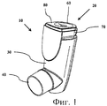
Фиг.1 изображает вид в аксонометрии ингалятора со счетчиком в соответствии с данным изобретением.Figure 1 depicts a perspective view of an inhaler with a counter in accordance with this invention.
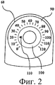
Фиг.2 изображает конструкцию дисплея в соответствии с данным изобретением.Figure 2 depicts the design of the display in accordance with this invention.
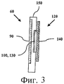
Фиг.3 изображает поперечное сечение дисплея, изображенного на фиг.2.Figure 3 depicts a cross section of the display depicted in figure 2.
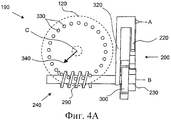
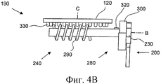
Фиг.4а-4с изображают вариант счетного механизма для счетчика ингалятора в соответствии с данным изобретением.Figures 4a-4c depict an embodiment of a counting mechanism for an inhaler meter in accordance with this invention.
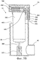
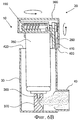
Фиг.5а и 5b изображают счетный механизм ингалятора, показанный на Фиг.4а-4с, на местных поперечных разрезах.Figures 5a and 5b depict the counting mechanism of the inhaler shown in Figures 4a-4c in local cross sections.
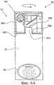
Фиг.6а и 6b иллюстрируют приведение в действие ингалятора и счетчика, показанных на фиг.5а и 5b.Figures 6a and 6b illustrate the actuation of the inhaler and meter shown in Figures 5a and 5b.
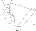
Фиг.7 изображает основные геометрические характеристики храпового устройства счетного механизма, показанного на Фиг.4а-4с.Fig.7 depicts the basic geometric characteristics of the ratchet device of the counting mechanism shown in Fig.4A-4C.
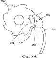
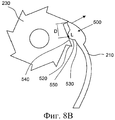
Фиг.8а и 8b изображают основные геометрические характеристики двух возможных вариантов храпового устройства, снабженных рычажным устройством, в соответствии сданным изобретением.Figa and 8b depict the basic geometric characteristics of two possible variants of a ratchet device equipped with a lever device in accordance with the invention.
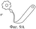
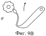
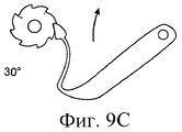
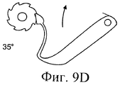
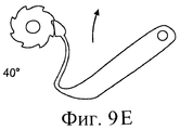
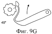
Фиг.9а-9h иллюстрируют вход в зацепление и выход из зацепления храпового устройства.9a-9h illustrate engagement and disengagement of a ratchet device.
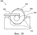
Фиг.10 изображает вынесенное пространственное изображение тормозного средства предотвращения обратного поворота счетного механизма, изображенного на фиг.4а-4с.Figure 10 depicts a remote spatial image of the brake means to prevent reverse rotation of the counting mechanism depicted in figa-4C.
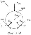
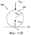
Фиг.11а и 11b иллюстрируют схематично силы, действующие в тормозном средстве предотвращения обратного поворота, показанном на фиг.9.FIGS. 11a and 11b illustrate schematically the forces acting in the reverse rotation brake means shown in FIG. 9.
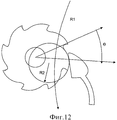
Фиг.12 изображает основные геометрические характеристики храповика счетного механизма, показанного на фиг.4а-4с.Fig. 12 depicts the basic geometric characteristics of the ratchet of the counting mechanism shown in Figs. 4a-4c.
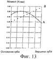
Фиг.13 изображает диаграмму, показывающую величину возвратного момента, прикладываемого от собачки к храповику, показанному на фиг.12.Fig. 13 is a diagram showing the magnitude of the return torque applied from the dog to the ratchet shown in Fig. 12.
Подробное описание предпочтительных вариантов выполнения изобретенияDETAILED DESCRIPTION OF PREFERRED EMBODIMENTS
На фиг.1 показан схематичный пример ингалятора 10, содержащего счетчик 20 в соответствии с данным изобретением. Ингалятор содержит корпус 30 приводного механизма с мундштуком 40, через который лекарственное средство подается пользователю, и блок контейнер-счетчик. В этом варианте выполнения изобретения счетчик 20 присоединен к концу контейнера ингалятора (не показан), размещенного в корпусе 30. Ингалятор 10 приводится в действие нажатием на блок контейнер-счетчик относительно корпуса 30. Счетчик 20 выполнен с обеспечением отсчитывания каждого срабатывания ингалятора 10 и отображения фактического состояния при помощи показывающего устройства 60. Кроме того, счетчик 20 может быть сконструирован как часть корпуса 30 или как съемная часть, присоединяемая к корпусу 30, например, с передней или задней его стороны.Figure 1 shows a schematic example of an
Согласно изобретению счетчик 20 находится на основании контейнера ингалятора. Счетчик 20 присоединяют к контейнеру ингалятора в процессе сборки, при этом он может быть присоединен к контейнеру ингалятора в любой из многочисленных точек вдоль конца контейнера, противоположного клапану, то есть к части контейнера, расположенной с другого конца от штока клапана, от наиболее удаленного края счетчика к его внутреннему основанию, что дает диапазон изменения положений и возможность варьирования величин допусков контейнера. То есть счетчик может быть присоединен где-нибудь в основании контейнера.According to the invention, the
В данном тексте имеется ссылка на «точку срабатывания», представляющую собой степень нажатия на контейнер ингалятора относительно корпуса приводного устройства, которое необходимо для подачи дозы медикамента, и «точку отсчета», представляющую собой степень нажатия на контейнер ингалятора относительно корпуса приводного устройства, которое необходимо для того, чтобы заставить счетчик 20 отсчитать одну дозу. Поскольку неполный подсчет не рекомендуется из-за того, что пользователь будет ошибочно полагать, что в контейнере ингалятора еще остается лекарство, в то время как контейнер фактически пуст, точка отсчета устанавливается на определенном расстоянии раньше, чем точка срабатывания, посредством чего эффективно устраняется срабатывание ингалятора без отсчета дозы.In this text, there is a link to the “trigger point”, which is the degree of pressure on the inhaler container relative to the body of the drive device, which is necessary to supply the dose of medication, and the “reference point”, which is the degree of pressure on the inhaler container relative to the body of the drive device, which is necessary in order to force the
Счетчик 20 в основном состоит из корпуса 70, счетного механизма (описанного подробно далее) и показывающего устройства 60. В варианте выполнения, показанном на фиг.1, показывающее устройство 60 расположено на верхней поверхности 80 корпуса 70. В раскрытом варианте конструкции верхняя поверхность 80 корпуса 70 выполнена в виде прозрачной отформованной детали 150, которая закрывает корпус 70. В раскрытом варианте конструкции верхняя поверхность 80 счетчика используется также в качестве нажимной поверхности для приведения в действие ингалятора 10, то есть для нажатия на блок контейнер-счетчик. Поскольку верхняя поверхность 80 счетчика используется как поверхность для нажима, она должна быть прочной и износостойкой, так как она будет подвергаться сжимающему усилию и износу во время приведения в действие ингалятора 10.The
Фиг.2 показывает вид сверху счетчика 20 с вариантом конструкции показывающего устройства 60 согласно данному изобретению. Показывающее устройство 60 содержит неподвижную 90 и подвижную 100 секции дисплея. В раскрытом варианте выполнения неподвижная секция 90 окружает подвижную секцию 100, которая сконструирована как поворотный элемент с указателем 110. Неподвижная секция 90 представляет собой кольцевую градуированную шкалу со значениями количества остающихся в контейнере доз, и таким образом угловое положение указателя 110 отражает фактическое количество доз. Такая конструкция позволяет достичь преимуществ при индикации количества остающихся в контейнере доз как при относительном, так и при точном способе индикации.Figure 2 shows a top view of the
На Фиг.3 показан поперечный разрез основных частей показывающего устройства 60 счетчика 20, изображенного на фиг.2. Подвижная секция 100 выполнена в виде колеса 120 указателя, поворотом которого управляет счетный механизм (описанный ниже). Колесо 120 содержит дисплейную часть 130 с указателем 110 и часть 140 счетного механизма, входящую в зацепление, в виде зубчатого колеса.Figure 3 shows a cross section of the main parts of the indicating
На фиг.4а-4с показан вариант выполнения счетного механизма 190 счетчика ингалятора, согласно данному изобретению, со снятым корпусом 70. Счетный механизм содержит кулису 200, возвратную пружину 220, вал 240 с храповиком 230 и поворотное колесо 120 указателя.Figures 4a-4c show an embodiment of the
Кулиса 200, имеющая собачку 210, шарнирно крепится к корпусу в точке А и смещается в нисходящем направлении при помощи возвратной пружины 220. Кулиса 200 содержит секцию 250 жесткого коромысла, которая проходит от точки А до его самой нижней точки 260 и примыкает к основанию корпуса, где коромысло вступает в контакт с выступом корпуса приводного механизма (как будет подробно показано далее), и гибкую собачку 210 с головкой 270, предназначенную для зацепления и поворота храповика 230 для получения шагового поворотного движения при приводном перемещении ингалятора.The
Вал 240 содержит, в дополнение к храповику 230, средство 280 предотвращения обратного поворота и червяк 290, расположенные на том же валу, закрепленном в конструкции корпуса (не показана), с возможностью поворота вокруг точки В. Средство 280 предотвращения обратного поворота представляет собой подпружиненный фрикционный тормоз, включающий тормозной диск 300, который прижимается к двум наклонным поверхностям 310 трения при помощи тормозной пружины 320. В данном варианте выполнения изобретения возвратная пружина 220 и тормозная пружина 320 выполнены в виде одного узла с двумя отдельными "упругими пластинами", проходящими от общей точки крепления к кожуху (не показан). Средство 280 будет описано более подробно далее.The
Колесо 120 является поворотным вокруг точки С и имеет периферический ряд зубьев 330, которые входят в зацепление с червяком 290, и указатель 340, показывающий отсчет доз на неподвижной шкале (не показанной на фиг.4а-4с). Таким образом, колесо 120 приводится во вращение вокруг точки С червяком 290, закрепленным на валу 240.
Фиг.6а и 5b показывают на местных разрезах счетный механизм 190 ингалятора 10, изображенный на фиг.4а-4с. Ингалятор 10 содержит корпус 30 приводного устройства, который содержит контейнер 350 с лекарственным веществом. Лекарство подается пользователю через шток 360 клапана, присоединенный с одного конца контейнера 350. Пользователь вдыхает лекарственное вещество через мундштук 40, являющийся частью корпуса 30. Мундштук 40 соединяется со штоком 360 клапана через приемную камеру 370, служащую для приема подаваемого лекарственного вещества. Кроме того, на конце контейнера 350, противоположном клапану 360, находится счетчик 20 доз. В раскрытых здесь вариантах конструкции счетчик 20 в предпочтительном случае постоянно присоединен к контейнеру 350, чтобы избежать того, что счетное устройство 20 будет снято с одного контейнера 350 и присоединено к другому контейнеру 350, содержащему другое лекарственное вещество. Контейнер 350 с присоединенным счетчиком 20 далее упоминается как емкостной узел ингалятора. Когда доза лекарственного вещества должна быть подана пользователю, нажимают на контейнерный узел ингалятора, в результате чего шток 360 клапана приводится в положение, при котором происходит подача дозы лекарственного вещества, или, другими словами, срабатывание ингалятора. Это соответствует многим известным ингаляторам и более подробно описываться здесь не будет.Figures 6a and 5b show, in local sections, the
Счетчик 20 содержит корпус 390 и счетный механизм 190, изображенный на фиг.4а-4с. Корпус 30 в своей направленной вниз стенке имеет отверстие 400, которое предназначено для введения выступа 410 верхнего края 420 корпуса 30 с образованием сопряжения. Когда нажимают на емкостной узел ингалятора, чтобы произошло срабатывание ингалятора 10, как показано на соответствующих фиг.6а и 6b, выступ 410 проходит через отверстие 400 в корпус 390 счетчика, входит в зацепление с нижней частью 260 кулисы 200 и таким образом приводит в действие счетный механизм 190.The
На фиг.7 показаны основные геометрические характеристики кулисы 200 и храповика 230 счетного механизма 190, приведенных на фиг.4а-4с. Теоретически, головка 270 собачки во время перемещения кулисы перемещается вдоль дуги окружности радиуса R, и процесс входа в зацепление и выхода из зацепления с храповиком 230 похож на зацепление двух шестерен. Однако чтобы собачка 210 поворачивала храповик 230 на требуемый угол, например на 45°, храповик 230 размещается ближе теоретического расстояния зацепления, в результате чего перемещение головки 270 собачки приводит к уменьшению радиуса хода после зацепления с храповиком 230. Таким образом, головка 270 собачки входит в зацепление с храповиком 230 на некоторый угол раньше, чем для теоретического расстояния зацепления, и наоборот, выходит из зацепления на некоторый угол позже. Для получения настраиваемого механизма, кулиса смещена в "неведущем" направлении, а собачка 210 выполнена упругой в радиальном направлении. Собачка 210 в направлении вдоль окружности имеет значительную жесткость.Fig.7 shows the basic geometric characteristics of the
Чтобы преодолеть стремление собачки 210 прогибаться радиально внутрь к оси вращения храповика в точке выхода из зацепления, точка выхода из зацепления эффективно контролируется тем, что собачка и храповое устройство снабжены рычажным устройством, предназначенным для осуществления выхода из зацепления собачки и зуба на храповике. Рычажное устройство предназначено для того, чтобы установить опорную поверхность собачки и храповика в точку рычага после указанного зуба относительно направления поворотного движения. Фиг.8а и 8b показывают примеры двух возможных вариантов выполнения рычажного средства 500 для управления выходом из зацепления собачки 210 и храповика 230. Чтобы рычажное средство 500 функционировало как средство управления выходом из зацепления, оно должно быть сконструировано так, чтобы точка L рычага была расположена на соответствующем расстоянии D от вершины головки собачки, в зависимости от необходимого угла выхода из зацепления, конструкции и физических характеристик собачки 210 и храповика 230. В варианте выполнения, показанном на фиг.8а, рычажное средство 500 образовано выпуклой тыльной поверхностью 510 зуба 520 храповика и плоской поверхностью 530 собачки счетчика. В варианте выполнения, показанном на фиг.8b, рычажное средство 500 образовано плоской тыльной поверхностью 540 зуба 520 храповика и выступом 550 на поверхности 530 собачки счетчика.In order to overcome the tendency of the
Фиг.9а-9h показывают последовательность входа в зацепление и выхода из зацепления для механизма 190 из храповика и собачки согласно одному из вариантов выполнения данного изобретения. Как можно заметить на фиг.9d, собачка и зуб на храповике сформированы так, чтобы точка рычага опорного зуба была установлена под углом, предшествующим требуемому углу выхода из зацепления. Далее, на фиг.9е можно заметить, что действие рычага воздействует на конец головки собачки в направлении выхода из зацепления относительно вершины зуба на храповике. Когда требуемый угол выхода из зацепления достигнут, как показано на фиг.9f и 9g, действие рычага в конечном счете приводит к управляемому выходу из зацепления головки собачки и зуба на храповике. Фиг.9h поясняет возврат в исходное положение кулисы, при котором обратному повороту храповика препятствует фрикционный тормоз 280, действие которого описано ниже более подробно.Figures 9a-9h show a gearing and disengaging sequence for a ratchet and
Как показано на фиг.8а-9b, точка рычага на храповике может быть расположена на тыльной поверхности последующего зуба, но она может быть расположена также и в любой другой соответствующей точке на храповике.As shown in figa-9b, the lever point on the ratchet may be located on the back surface of the subsequent tooth, but it can also be located at any other corresponding point on the ratchet.
По сравнению с использованием отдельной направляющей поверхности согласно патенту США №6446627, применение рычажного средства 500 для управления выходом из зацепления имеет очевидное преимущество в том, что этот способ базируется исключительно на непосредственном взаимодействии между собачкой 210 и храповиком 230 и не зависит от дополнительных деталей. Как упоминалось выше, счетчики доз для ингалятора имеют ограничения по размерам и затратам на изготовление, при одновременном требовании к обеспечению высокой точности. Поэтому любое уменьшение количества взаимодействующих деталей приводит к увеличению точности.Compared to using a separate guide surface according to US Pat. No. 6,446,627, the use of the lever means 500 for controlling the disengagement has the obvious advantage that this method is based solely on the direct interaction between the
Фиг.10 показывает вынесенное пространственное изображение средства 280 предотвращения обратного поворота счетного механизма 190, показанного на фиг.4а-4с. В данном варианте выполнения изобретения тормозное средство 280 состоит из цилиндрического элемента 300, находящегося между двумя наклонными поверхностями 310 трения, образующими V-образную компоновку; цилиндрический элемент 300 связан с вращающимся храповиком 230 и механизмом собачки и прижимается к поверхностям 310 трения пружинным элементом 320. В описываемом варианте конструкции наклонные поверхности трения параллельны оси вращения элемента 300.FIG. 10 shows a spatial exploded view of the
На фиг.11а схематично показаны силы, действующие в тормозном средстве 280, изображенном на фиг.9, а на фиг.11b показаны силы, действующие на одной из поверхностей 310 трения фрикционного тормозного устройства. Момент Mbrake сил трения, тормозящий поворот цилиндрического элемента 300, согласно фиг.11b вычисляется просто (предполагается, что момент сил трения между пружиной 320 и валом 240 незначителен):On figa schematically shows the forces acting in the brake means 280, shown in Fig.9, and Fig.11b shows the forces acting on one of the friction surfaces 310 of the friction brake device. The moment M brake of the friction forces that inhibits the rotation of the
Mbrake=FspringµRbrake M brake = F spring µR brake
где Fspring - вертикальная составляющая силы действия пружины 320, µ - коэффициент трения скольжения между цилиндрическим элементом 300 и поверхностью 310 трения, a Rbrake - радиус цилиндрического элемента 300.where F spring is the vertical component of the
На предыдущем фиг.11а нормальные силы Fincl, действующие на цилиндрический элемент 300 от наклонных поверхностей 310, дают следующую величину момента сил трения Mbrake:In the previous figa normal forces F incl , acting on the
Mbreak=2µRbreak M break = 2µR break
В варианте выполнения изобретения на фиг.11а наклонные поверхности 310 расположены под углом соответственно +/-45° относительно направления силы Fspring, в результате чего результирующий момент сил трения Mbrake равен:In the embodiment of the invention in FIG. 11a, the
Mbreak=√2FspringµRbreak M break = √2F spring µR break
Таким образом, результирующий момент сил трения в √2=1,41 раз больше, чем в случае одной плоской поверхности трения 310. Выбирая углы наклона поверхностей 310, усилие пружины Fspring и коэффициент трения между цилиндрическим элементом 300 и наклонными поверхностями 310, можно регулировать тормозной момент до заданного значения, как это необходимо для конструкции счетного механизма. В рассматриваемом варианте конструкции угол между поверхностями трения менее 120°, предпочтительно менее 110° (в наиболее предпочтительном случае - менее 100°), и более 60°, предпочтительно более 75° (в наиболее предпочтительном случае - более 80°). Даже при том, что теоретически более эффективно иметь большее количество поверхностей 310 трения или точек фрикционного контакта, количество поверхностей 310 предпочтительно ограничивается двумя, поскольку в случае массового производства труднее обеспечивать заданные результирующие силы для более чем двух поверхностей 310.Thus, the resulting moment of friction forces is √2 = 1.41 times greater than in the case of one
В рассматриваемом варианте выполнения (фиг.4а-11а) пружина 320 прикладывает усилие Fspring к цилиндрическому элементу 300 в направлении, по существу противоположном направлению перемещения собачки 210, при продвижении элементов дисплея путем шагового поворота храповика 230 и вала 240. При такой конструкции сила, прикладываемая собачкой 210 к храповику 230, будет приводить к меньшему тормозному моменту Mbrake и поворот храповика 230 в прямом направлении будет осуществляться легче. Однако, во время его перемещения в начальное положение собачка 210 будет прилагать усилие практически в том же направлении, что и усилие Fspring, посредством чего тормозной момент Mbrake будет увеличиваться и поворот в обратном направлении будет эффективно предотвращаться.In the present embodiment (FIGS. 4a-11a), the
Чтобы гарантировать, что необходимый тормозной момент Mbrake достигнут, средство 280 функционирует как подшипниковая опора для одного конца вала 240. Согласно раскрытому на фиг.5а-6b варианту выполнения изобретения узел вала снабжен вторым опорным элементом 430 на конце червяка 290 и боковыми центрующими средствами 440, находящимися между средством 280 и червяком 290.To ensure that the required braking torque M brake is reached, the
Чтобы еще более уменьшить риск обратного поворота храповика 230 во время перемещения в начальное положение собачки 210, была оптимизирована геометрия храповых зубьев, чтобы уменьшить максимальный возвратный момент, прикладываемый собачкой 210 к храповику 230. Оптимальная геометрия, определенная в результате оптимизации, получается для случая, когда зубья имеют выпуклую тыльную поверхность, как показано на фиг.12. На фиг.13 показана зависимость результирующего возвратного момента от угла возврата в начальное положение для выпуклого зуба в виде сплошной линии А, и для условного зуба с прямолинейным профилем (см. фиг.8b) в виде пунктирной линии В. По сравнению с зубом с плоской тыльной поверхностью, у зуба с выпуклой тыльной поверхностью имеется более высокий начальный момент, поскольку вершина собачки во время перемещения в начальное положение прижимается к центру вращения зуба раньше, но после этого момент уменьшается, поскольку вершина собачки приближается к вершине зуба. Более высокий момент при старте соответствует действию пружины; поэтому пружина может обеспечить необходимый возвратный момент. Поскольку возвратный момент для зуба с плоской тыльной поверхностью увеличивается линейно и достигает своего максимального значения в вершине зуба, максимальный вращающий момент имеет большую величину для зуба с плоской тыльной поверхностью, а также пик соответствует растянутой пружине - поэтому такой профиль зуба хуже обеспечивает заданный возвратный момент.To further reduce the risk of the
Кривизна выпуклой тыльной поверхности храповика и механизма собачки для минимизации максимального возвратного момента выбирается расчетным способом в зависимости от следующих параметров: диаметр храповика, кривизна тыльной поверхности храповых зубьев, коэффициент трения между материалом храповика и материалом собачки, жесткость пружины собачки.The curvature of the convex rear surface of the ratchet and the dog mechanism to minimize the maximum return moment is selected by calculation using the following parameters: ratchet diameter, curvature of the back surface of the ratchet teeth, coefficient of friction between the ratchet material and the dog material, the stiffness of the dog spring.
Также разработан способ изготовления храпового механизма с храповиком и собачкой для преобразования линейного приводного перемещения в поворотное движение, при помощи которого прокручивается дисплей, показывающий количество доступных в ингаляторе доз лекарства, включающий следующие этапы:A method has also been developed for manufacturing a ratchet mechanism with ratchet and a dog for converting linear drive movement into rotary movement, by means of which a display scrolls, showing the number of doses of medicine available in the inhaler, including the following steps:
выбор диаметра, количества зубьев и материала для храпового колеса,selection of diameter, number of teeth and material for the ratchet wheel,
выбор формы и материала для собачки,the choice of shape and material for the dog,
минимизация максимального возвратного момента для указанного храпового механизма путем изготовления зубьев храповика с выпуклой тыльной поверхностью,minimizing the maximum return moment for the specified ratchet mechanism by manufacturing ratchet teeth with a convex rear surface,
при этом изготовление зубьев храповика с выпуклой тыльной поверхностью включает определение кривизны тыльной поверхности храповых зубов путем расчета возвратного момента в зависимости от следующих параметров: диаметр храпового колеса, кривизна тыльной поверхности храповых зубьев, коэффициент трения между материалом храпового колеса и материалом собачки, жесткость пружины собачки.the manufacture of ratchet teeth with a convex rear surface includes determining the curvature of the back surface of the ratchet teeth by calculating the return torque depending on the following parameters: the diameter of the ratchet wheel, the curvature of the back surface of the ratchet teeth, the friction coefficient between the ratchet wheel material and the dog material, the stiffness of the dog spring.
Claims (20)
выбор диаметра, количества зубьев и материала храповика,
выбор формы и материала собачки,
минимизацию максимального возвратного момента для механизма храповика и собачки путем выполнения зубьев храповика с выпуклой тыльной поверхностью,
при этом при выполнении зубьев храповика с выпуклой тыльной поверхностью определяют кривизну указанной поверхности путем расчета указанного возвратного момента в зависимости от следующих параметров: диаметр храповика, коэффициент трения между материалом храповика и материалом собачки и жесткость пружины собачки.13. A method of manufacturing a mechanism including a ratchet and a dog and designed to convert a linear drive movement into a rotary movement with the promotion of the indicating device, including:
selection of diameter, number of teeth and ratchet material,
the choice of shape and material of the dog,
minimization of the maximum return moment for the ratchet and dog mechanism by performing ratchet teeth with a convex rear surface,
at the same time, when performing ratchet teeth with a convex rear surface, the curvature of the indicated surface is determined by calculating the specified return moment depending on the following parameters: ratchet diameter, coefficient of friction between the ratchet material and the dog material and the stiffness of the dog spring.
корпус (390),
кулису (200) с собачкой (210), закрепленную шарнирно на корпусе и расположенную с возможностью колебательного перемещения под воздействием линейного приводного перемещения, возвратную пружину (220), предназначенную для возврата кулисы (200) в исходное положение, храповик (230), выполненный с возможностью зацепления с собачкой для преобразования перемещения кулисы в шаговое поворотное перемещение вала (240) с обеспечением продвижения показывающего средства (60), причем вал дополнительно содержит средство (280) предотвращения обратного поворота, выполненное в виде подпружиненного фрикционного тормоза, и червяк (290), а показывающее средство содержит поворотные средства (120) индикации с зубьями (330), которые входят в зацепление с червяком, и неподвижную шкалу (90).14. The counter (20) of the inhaler containing:
case (390),
rocker (200) with a dog (210), pivotally mounted on the housing and located with the possibility of oscillatory movement under the influence of linear drive movement, a return spring (220), designed to return the wings (200) to its original position, ratchet (230), made with the possibility of engagement with the dog to convert the movement of the scenes into a stepwise rotary movement of the shaft (240) with the advancement of showing means (60), and the shaft further comprises means (280) for preventing reverse rotation, a spring-loaded friction brake, and a worm (290), and the indicating means comprises rotary indicating means (120) with teeth (330), which engage with the worm, and a fixed scale (90).
Applications Claiming Priority (2)
| Application Number | Priority Date | Filing Date | Title |
|---|---|---|---|
| SE0500857-8 | 2005-04-14 | ||
| SE0500857 | 2005-04-14 |
Publications (2)
| Publication Number | Publication Date |
|---|---|
| RU2007140549A RU2007140549A (en) | 2009-05-20 |
| RU2388052C2 true RU2388052C2 (en) | 2010-04-27 |
Family
ID=37087283
Family Applications (1)
| Application Number | Title | Priority Date | Filing Date |
|---|---|---|---|
| RU2007140549/09A RU2388052C2 (en) | 2005-04-14 | 2006-04-10 | Inhalator counter |
Country Status (33)
| Country | Link |
|---|---|
| US (2) | US7587988B2 (en) |
| EP (2) | EP2955669A1 (en) |
| JP (2) | JP4954976B2 (en) |
| KR (2) | KR101269478B1 (en) |
| CN (1) | CN100594513C (en) |
| AR (1) | AR055910A1 (en) |
| AT (2) | AT10425U1 (en) |
| AU (3) | AU2006234785B2 (en) |
| BG (1) | BG1354U1 (en) |
| BR (1) | BRPI0609459B8 (en) |
| CA (2) | CA2603925C (en) |
| CZ (1) | CZ18311U1 (en) |
| DE (1) | DE212006000031U1 (en) |
| DK (1) | DK200700256U4 (en) |
| EE (1) | EE00721U1 (en) |
| EG (1) | EG25113A (en) |
| ES (1) | ES2547929T3 (en) |
| FI (1) | FI7914U1 (en) |
| HK (2) | HK1112089A1 (en) |
| IL (1) | IL186225A (en) |
| MX (1) | MX2007012539A (en) |
| MY (2) | MY143551A (en) |
| NO (1) | NO20075848L (en) |
| NZ (1) | NZ562000A (en) |
| RU (1) | RU2388052C2 (en) |
| SA (1) | SA06270091B1 (en) |
| SG (1) | SG144913A1 (en) |
| SK (1) | SK50762007U1 (en) |
| TW (1) | TWI442951B (en) |
| UA (1) | UA90709C2 (en) |
| UY (1) | UY29474A1 (en) |
| WO (1) | WO2006110080A1 (en) |
| ZA (1) | ZA200708220B (en) |
Cited By (2)
| Publication number | Priority date | Publication date | Assignee | Title |
|---|---|---|---|---|
| RU2601108C2 (en) * | 2011-05-04 | 2016-10-27 | Сипла Лимитед | Counter doses |
| RU189757U1 (en) * | 2019-01-09 | 2019-06-03 | Федеральное государственное бюджетное учреждение "48 Центральный научно-исследовательский институт" Министерства обороны Российской Федерации | DISK SPRAYER FOR OBTAINING POLYDISPERS AEROSOLS FROM POWDERED MATERIALS |
Families Citing this family (68)
| Publication number | Priority date | Publication date | Assignee | Title |
|---|---|---|---|---|
| CA2315777C (en) | 1998-01-16 | 2008-12-23 | 1263152 Ontario Inc. | Indicating device for use with a dispensing device |
| US6082358A (en) | 1998-05-05 | 2000-07-04 | 1263152 Ontario Inc. | Indicating device for aerosol container |
| US7004164B2 (en) | 2002-03-21 | 2006-02-28 | Trudell Medical International | Indicating device for aerosol container |
| US7621273B2 (en) | 2003-10-28 | 2009-11-24 | Trudell Medical International | Indicating device with warning dosage indicator |
| US7100530B2 (en) | 2003-12-15 | 2006-09-05 | Trudell Medical International, Inc. | Dose indicating device |
| GB2414187B (en) * | 2004-05-21 | 2007-03-07 | Bespak Plc | Dispensing apparatus |
| US7543582B2 (en) | 2004-09-20 | 2009-06-09 | Trudell Medical International | Dose indicating device with display elements attached to container |
| GB0425518D0 (en) | 2004-11-19 | 2004-12-22 | Clinical Designs Ltd | Substance source |
| GB0428204D0 (en) | 2004-12-23 | 2005-01-26 | Clinical Designs Ltd | Medicament container |
| JP5189369B2 (en) | 2005-01-20 | 2013-04-24 | トルーデル メディカル インターナショナル | Dispensing device |
| TWI442951B (en) * | 2005-04-14 | 2014-07-01 | Astrazeneca Ab | Inhaler counter |
| JP5295769B2 (en) * | 2005-08-31 | 2013-09-18 | ティツー・バイオシステムズ・インコーポレーテッド | NMR apparatus for detecting analytes |
| GB0518400D0 (en) | 2005-09-09 | 2005-10-19 | Clinical Designs Ltd | Dispenser |
| GB2448838B (en) | 2006-05-26 | 2009-02-11 | Consort Medical Plc | Improvements in or relating to dispensing apparatus |
| GB0610541D0 (en) | 2006-05-26 | 2006-07-05 | Bespak Plc | Improvements in or relating to dispensing apparatus |
| GB0613472D0 (en) * | 2006-07-06 | 2006-08-16 | Glaxo Group Ltd | A counter and a recorder for a pill dispenser |
| US8141550B2 (en) | 2006-08-01 | 2012-03-27 | Trudell Medical International | Dispensing device |
| GB2448112B (en) * | 2007-01-16 | 2011-08-17 | Bespak Plc | Improvements in or relating to dispensing apparatus |
| GB0706405D0 (en) * | 2007-04-02 | 2007-05-09 | 3M Innovative Properties Co | Dose counter |
| EP2196234A4 (en) * | 2007-09-26 | 2014-12-17 | Otsuka Pharma Co Ltd | Metered dose inhaler |
| EP2077132A1 (en) | 2008-01-02 | 2009-07-08 | Boehringer Ingelheim Pharma GmbH & Co. KG | Dispensing device, storage device and method for dispensing a formulation |
| US8656911B2 (en) | 2008-02-18 | 2014-02-25 | Glaxosmithkline Intellectual Property Development Limited | Actuation counter |
| US8082873B2 (en) | 2008-05-05 | 2011-12-27 | Trudell Medical International | Drive mechanism for an indicating device |
| US8181591B1 (en) | 2008-05-23 | 2012-05-22 | Trudell Medical International | Domed actuator for indicating device |
| EP2626098B1 (en) | 2008-10-22 | 2020-08-19 | Trudell Medical International | Modular aerosol delivery system |
| GB0904059D0 (en) | 2009-03-10 | 2009-04-22 | Euro Celtique Sa | Counter |
| GB0904040D0 (en) | 2009-03-10 | 2009-04-22 | Euro Celtique Sa | Counter |
| US10011906B2 (en) | 2009-03-31 | 2018-07-03 | Beohringer Ingelheim International Gmbh | Method for coating a surface of a component |
| EP3508239B1 (en) | 2009-05-18 | 2020-12-23 | Boehringer Ingelheim International GmbH | Adapter, inhalant apparatus and atomizer |
| GB0909363D0 (en) * | 2009-06-01 | 2009-07-15 | Reckitt Benckiser Nv | Detergent dispensing device |
| CA2769241C (en) | 2009-07-30 | 2014-11-25 | Ivax International B.V. | Dose counter for a metered-dose inhaler |
| US9216261B2 (en) | 2009-07-30 | 2015-12-22 | Ivax International B.V. | Dose counter for a metered-dose inhaler |
| US8539945B2 (en) | 2009-08-18 | 2013-09-24 | Teva Pharmaceutical Industries Ltd. | Dose counter and recording method |
| WO2011064163A1 (en) | 2009-11-25 | 2011-06-03 | Boehringer Ingelheim International Gmbh | Nebulizer |
| US10016568B2 (en) | 2009-11-25 | 2018-07-10 | Boehringer Ingelheim International Gmbh | Nebulizer |
| UA107097C2 (en) | 2009-11-25 | 2014-11-25 | Бьорінгер Інгельхайм Інтернаціональ Гмбх | Dispenser |
| US9084864B1 (en) | 2010-03-04 | 2015-07-21 | Barthel LLC | Adaptor for breathing tube and method |
| EA026306B1 (en) | 2010-05-18 | 2017-03-31 | Ивакс Фармасьютикалз Аэрлэнд | Method for assembly of a dose counter for an inhaler, and a tape system |
| FR2961186B1 (en) * | 2010-06-11 | 2012-07-13 | Valois Sas | DEVICE FOR DISPENSING FLUID PRODUCT. |
| EP2585151B1 (en) | 2010-06-24 | 2018-04-04 | Boehringer Ingelheim International GmbH | Nebulizer |
| WO2012130757A1 (en) | 2011-04-01 | 2012-10-04 | Boehringer Ingelheim International Gmbh | Medical device comprising a container |
| US9827384B2 (en) | 2011-05-23 | 2017-11-28 | Boehringer Ingelheim International Gmbh | Nebulizer |
| WO2013045996A1 (en) | 2011-09-26 | 2013-04-04 | Trudell Medical International | Dose counter and medication delivery device |
| WO2013152894A1 (en) | 2012-04-13 | 2013-10-17 | Boehringer Ingelheim International Gmbh | Atomiser with coding means |
| GB201215917D0 (en) | 2012-09-06 | 2012-10-24 | 3M Innovative Properties Co | Improvements in or relating to dose indicators |
| ES2836977T3 (en) | 2013-08-09 | 2021-06-28 | Boehringer Ingelheim Int | Nebulizer |
| WO2015018904A1 (en) | 2013-08-09 | 2015-02-12 | Boehringer Ingelheim International Gmbh | Nebulizer |
| AU356087S (en) * | 2013-11-29 | 2014-06-23 | Norton Waterford Ltd | Respiratory apparatus |
| AU356086S (en) * | 2013-11-29 | 2014-06-23 | Norton Waterford Ltd | Respiratory apparatus |
| US10195374B2 (en) | 2014-05-07 | 2019-02-05 | Boehringer Ingelheim International Gmbh | Container, nebulizer and use |
| GB201406046D0 (en) | 2014-04-03 | 2014-05-21 | 3M Innovative Properties Co | Dose indicator or dose counter |
| KR102492824B1 (en) | 2014-05-07 | 2023-01-30 | 베링거 인겔하임 인터내셔날 게엠베하 | Nebulizer, indicator device and container |
| WO2015169430A1 (en) | 2014-05-07 | 2015-11-12 | Boehringer Ingelheim International Gmbh | Nebulizer |
| CN208301948U (en) * | 2014-07-22 | 2019-01-01 | 阿克什·彭加比 | Dosage measuring structure |
| CA2958883C (en) | 2014-08-28 | 2024-01-02 | Microdose Therapeutx, Inc. | Compliance monitoring module for an inhaler |
| CA3011901A1 (en) | 2016-01-21 | 2017-07-27 | T2 Biosystems, Inc. | Nmr methods and systems for the rapid detection of bacteria |
| ES2915559T3 (en) | 2016-02-17 | 2022-06-23 | Adherium Nz Ltd | Adherence monitor for a medication inhaler with cap attached |
| DE102016106875A1 (en) * | 2016-04-13 | 2017-10-19 | Alfred Von Schuckmann | Hand-held device for dispensing a pharmaceutical substance and counter for such a hand-held device |
| ES2913089T3 (en) * | 2017-02-20 | 2022-05-31 | Presspart Gmbh & Co Kg | metered dose inhaler |
| GB201706505D0 (en) | 2017-04-25 | 2017-06-07 | 3M Innovative Properties Co | Medicinal inhaler drive mechanism |
| CA3073195A1 (en) | 2017-08-15 | 2019-02-21 | Nephron Pharmaceuticals Corporation | Aqueous nebulization composition |
| US11419995B2 (en) | 2019-04-30 | 2022-08-23 | Norton (Waterford) Limited | Inhaler system |
| JP2022532678A (en) | 2019-05-17 | 2022-07-15 | ノートン (ウォーターフォード) リミテッド | Drug delivery device with electronic device |
| CN117677417A (en) | 2021-07-08 | 2024-03-08 | 阿斯利康(瑞典)有限公司 | Apparatus and system for detection and analysis of inhaler usage |
| CN113562340B (en) * | 2021-07-27 | 2022-04-12 | 吉林大学 | Convenient to use's intracardiac branch of academic or vocational study patient is with nursing first aid device |
| CN114558210B (en) * | 2022-03-04 | 2023-11-07 | 上海华瑞气雾剂有限公司 | Driver with spraying frequency indication and method |
| KR20240003479A (en) * | 2022-07-01 | 2024-01-09 | 주식회사 케이티앤지 | Inhaler |
| CN117205413B (en) * | 2023-11-07 | 2024-02-13 | 正大天晴(广州)医药有限公司 | Dose indicator |
Family Cites Families (28)
| Publication number | Priority date | Publication date | Assignee | Title |
|---|---|---|---|---|
| US1936126A (en) * | 1928-11-19 | 1933-11-21 | John R Daly | Register mechanism |
| DE519669C (en) * | 1929-07-03 | 1931-03-03 | Albert Eisele Dipl Ing | Stroke counter |
| US1942621A (en) * | 1931-05-22 | 1934-01-09 | James C Thompson | Rotary registering device |
| US2174668A (en) * | 1936-07-13 | 1939-10-03 | Naylor Patents Corp | Hand brake |
| US2582755A (en) * | 1947-05-08 | 1952-01-15 | Kenny Richard Joseph | Internal expanding brake |
| US2636469A (en) * | 1952-01-09 | 1953-04-28 | Hosmere C Mckay | Capsule dispenser |
| DE1549991A1 (en) * | 1967-08-01 | 1972-11-09 | Hengstler Kg | Transmission pinion for the drive circuit of two adjacent Wertverkoerperungsträger a mechanical counter with serving device |
| DE1800907A1 (en) * | 1968-10-03 | 1970-06-11 | Merk Gmbh Telefonbau Fried | Stepping drive for payment mechanisms, display devices, rotary switches and the like |
| CA1258054A (en) | 1986-04-25 | 1989-08-01 | Robert E. Newell | Indicating device |
| JPH0536100Y2 (en) * | 1989-05-02 | 1993-09-13 | ||
| GB9025654D0 (en) * | 1990-11-26 | 1991-01-09 | Riker Laboratories Inc | Device |
| FR2721106B1 (en) | 1994-06-10 | 1996-09-13 | Step | Dose counter for inhalers. |
| US5482030A (en) * | 1994-06-13 | 1996-01-09 | Klein; David | Aerosol and non-aerosol spray counter |
| GB2320489A (en) | 1996-12-20 | 1998-06-24 | Norton Healthcare Ltd | Inhaler dose counter |
| TW533865U (en) | 1997-06-10 | 2003-05-21 | Glaxo Group Ltd | Dispenser for dispensing medicament and actuation indicating device |
| CA2315777C (en) * | 1998-01-16 | 2008-12-23 | 1263152 Ontario Inc. | Indicating device for use with a dispensing device |
| US6082358A (en) | 1998-05-05 | 2000-07-04 | 1263152 Ontario Inc. | Indicating device for aerosol container |
| DE29814647U1 (en) | 1998-08-14 | 1999-12-23 | Wischerath Josef Gmbh Co Kg | Inhaler with a metering device |
| IT1312426B1 (en) * | 1999-06-30 | 2002-04-17 | Microspray Delta Spa | DISPENSER OF DOSES OF A LIQUID, WITH A DEVICE FOR COUNTING A HIGH NUMBER OF DOSES DISPENSED |
| TWI224513B (en) | 2000-06-23 | 2004-12-01 | Norton Healthcare Ltd | Dose counter for medicament inhaler |
| GB0019715D0 (en) | 2000-08-10 | 2000-09-27 | Pa Consulting Services | Device for delivering physiologically active agent in powdered form |
| US7101530B2 (en) * | 2003-05-06 | 2006-09-05 | Air Products And Chemicals, Inc. | Hydrogen storage by reversible hydrogenation of pi-conjugated substrates |
| US7100530B2 (en) * | 2003-12-15 | 2006-09-05 | Trudell Medical International, Inc. | Dose indicating device |
| DE202005021637U1 (en) | 2004-09-04 | 2009-01-22 | Schuckmann, Alfred Von | Inhale device |
| WO2006027333A1 (en) | 2004-09-04 | 2006-03-16 | Alfred Von Schuckmann | Inhaler device |
| GB0425518D0 (en) | 2004-11-19 | 2004-12-22 | Clinical Designs Ltd | Substance source |
| WO2006062450A1 (en) | 2004-12-10 | 2006-06-15 | Ernst Hörlins Ingenjösbyra Ab | Dose indicator for a dose inhaler |
| TWI442951B (en) * | 2005-04-14 | 2014-07-01 | Astrazeneca Ab | Inhaler counter |
-
2006
- 2006-04-07 TW TW095112405A patent/TWI442951B/en not_active IP Right Cessation
- 2006-04-10 CN CN200680021418A patent/CN100594513C/en active Active
- 2006-04-10 MX MX2007012539A patent/MX2007012539A/en active IP Right Grant
- 2006-04-10 KR KR1020077023537A patent/KR101269478B1/en active IP Right Grant
- 2006-04-10 NZ NZ562000A patent/NZ562000A/en unknown
- 2006-04-10 EE EEU200700113U patent/EE00721U1/en active Protection Beyond IP Right Term
- 2006-04-10 SA SA06270091A patent/SA06270091B1/en unknown
- 2006-04-10 CA CA2603925A patent/CA2603925C/en active Active
- 2006-04-10 SG SG200805115-3A patent/SG144913A1/en unknown
- 2006-04-10 US US11/570,747 patent/US7587988B2/en active Active
- 2006-04-10 EP EP15172432.5A patent/EP2955669A1/en not_active Withdrawn
- 2006-04-10 WO PCT/SE2006/000423 patent/WO2006110080A1/en active Application Filing
- 2006-04-10 UA UAA200710650A patent/UA90709C2/en unknown
- 2006-04-10 ES ES06733279.1T patent/ES2547929T3/en active Active
- 2006-04-10 AT AT0900306U patent/AT10425U1/en not_active IP Right Cessation
- 2006-04-10 SK SK5076-2007U patent/SK50762007U1/en unknown
- 2006-04-10 CA CA2813514A patent/CA2813514C/en active Active
- 2006-04-10 RU RU2007140549/09A patent/RU2388052C2/en active
- 2006-04-10 DE DE212006000031U patent/DE212006000031U1/en not_active Expired - Lifetime
- 2006-04-10 CZ CZ200719271U patent/CZ18311U1/en not_active IP Right Cessation
- 2006-04-10 EP EP06733279.1A patent/EP1875412B1/en active Active
- 2006-04-10 AU AU2006234785A patent/AU2006234785B2/en active Active
- 2006-04-10 JP JP2008506403A patent/JP4954976B2/en active Active
- 2006-04-10 BR BRPI0609459A patent/BRPI0609459B8/en active IP Right Grant
- 2006-04-12 MY MYPI20091098A patent/MY143551A/en unknown
- 2006-04-12 MY MYPI20061676A patent/MY140852A/en unknown
- 2006-04-12 AR ARP060101478A patent/AR055910A1/en active IP Right Grant
- 2006-04-12 UY UY29474A patent/UY29474A1/en not_active Application Discontinuation
-
2007
- 2007-09-24 IL IL186225A patent/IL186225A/en active IP Right Grant
- 2007-09-26 ZA ZA200708220A patent/ZA200708220B/en unknown
- 2007-09-30 EG EGNA2007001041 patent/EG25113A/en active
- 2007-10-05 DK DK200700256U patent/DK200700256U4/en not_active IP Right Cessation
- 2007-10-11 BG BG1369U patent/BG1354U1/en unknown
- 2007-10-12 KR KR2020070016620U patent/KR200444832Y1/en not_active IP Right Cessation
- 2007-10-15 FI FI20070407U patent/FI7914U1/en not_active IP Right Cessation
- 2007-11-14 NO NO20075848A patent/NO20075848L/en not_active Application Discontinuation
-
2008
- 2008-06-13 HK HK08106555.6A patent/HK1112089A1/en unknown
- 2008-06-13 HK HK16102538.7A patent/HK1214669A1/en unknown
- 2008-08-25 AT AT0044708U patent/AT10426U1/en not_active IP Right Cessation
-
2009
- 2009-09-08 US US12/555,559 patent/US7819075B2/en active Active
- 2009-10-29 AU AU2009233603A patent/AU2009233603B2/en active Active
- 2009-12-14 AU AU2009248469A patent/AU2009248469B2/en active Active
-
2011
- 2011-09-20 JP JP2011204854A patent/JP5325958B2/en active Active
Cited By (2)
| Publication number | Priority date | Publication date | Assignee | Title |
|---|---|---|---|---|
| RU2601108C2 (en) * | 2011-05-04 | 2016-10-27 | Сипла Лимитед | Counter doses |
| RU189757U1 (en) * | 2019-01-09 | 2019-06-03 | Федеральное государственное бюджетное учреждение "48 Центральный научно-исследовательский институт" Министерства обороны Российской Федерации | DISK SPRAYER FOR OBTAINING POLYDISPERS AEROSOLS FROM POWDERED MATERIALS |
Also Published As
Similar Documents
| Publication | Publication Date | Title |
|---|---|---|
| RU2388052C2 (en) | Inhalator counter | |
| US6446627B1 (en) | Inhaler dose counter | |
| EP1362324B1 (en) | Dosage counting devices | |
| CZ295757B6 (en) | Mechanical counter for a metering apparatus and inhaler of metered doses | |
| GB2429166A (en) | Inhaler counter | |
| WO2007045904A1 (en) | Dose counter for inhalation devices | |
| MX2011009525A (en) | Counter. | |
| US8381719B1 (en) | Medicament delivery system with dose indicator and oversleeve actuator | |
| WO2007012861A1 (en) | Canister-supported gauge-type count readout assembly for a metered dose inhaler |