RU2386005C2 - Drilling method of hard rocks with hydrotransport of core sample and drilling assembly for its implementation - Google Patents
Drilling method of hard rocks with hydrotransport of core sample and drilling assembly for its implementation Download PDFInfo
- Publication number
- RU2386005C2 RU2386005C2 RU2007147527/03A RU2007147527A RU2386005C2 RU 2386005 C2 RU2386005 C2 RU 2386005C2 RU 2007147527/03 A RU2007147527/03 A RU 2007147527/03A RU 2007147527 A RU2007147527 A RU 2007147527A RU 2386005 C2 RU2386005 C2 RU 2386005C2
- Authority
- RU
- Russia
- Prior art keywords
- core
- drilling
- drill
- diamond
- channels
- Prior art date
Links
Images


Abstract
Description
Изобретение относится к области бурения скважин в крепких породах, а именно к технологии и технике бурения с гидротранспортом керна, и обеспечивает повышение производительности бурения.The invention relates to the field of drilling wells in hard rocks, and in particular to technology and techniques for drilling with core hydrotransport, and provides improved drilling performance.
Известен способ бурения с транспортировкой керна восходящим потоком очистного агента с устройством для его осуществления (см. Патент США №3552779, кл. 175-215, опублик. 1971 г.), включающий бурильные трубы, сальник с керноотводом, кернолом, керноприемную трубу и коронку. При бурении при этом способе выбуренный керн верхним своим торцом упирается в клин кернолома, отклоняется от оси скважины и скалывается.A known method of drilling with core transport by upstream treatment agent with a device for its implementation (see US Patent No. 3552779, CL 175-215, published. 1971), including drill pipe, stuffing box with core tap, core, core receiver pipe and crown . When drilling with this method, the drilled core with its upper end abuts against the wedge of the core breaker, deviates from the axis of the well and is chipped.
Недостатком этого способа является то, что в начале бурения не определяется критическая скорость восходящего потока, обеспечивающая вынос шлама и керна на поверхность, не поддерживается критическое значение скорости углубки скважины путем изменения режимных параметров, а кернолом устанавливается в керноприемной трубе на произвольном расстоянии от торца буровой коронки, в результате при бурении образуются столбики керна не оптимальной длины с точки зрения требований условий его гидротранспорта в бурильных трубах и отводной трубе сальника, что приводит к снижению производительности бурения вследствие неравномерной скорости движения шлама и керна и возникающих по этой причине шламонакоплении и пробкообразовании на забое и подклинки керна в бурильных трубах (керноводе).The disadvantage of this method is that at the beginning of drilling the critical velocity of the upward flow, which ensures the removal of cuttings and core to the surface, is not supported, the critical value of the velocity of the well’s well is not supported by changing the operating parameters, and the core is installed in the core collection pipe at an arbitrary distance from the end of the drill bit , as a result, while drilling, core columns of not optimal length are formed from the point of view of the requirements of the conditions of its hydraulic transport in drill pipes and drain pipe bog, which leads to a decrease in drilling productivity due to the uneven speed of movement of the sludge and core and the resulting sludge accumulation and cork formation at the bottom and core sticks in drill pipes (core conduit).
Наиболее близким по технической сущности является способ бурения крепких пород с гидротранспортом керна, включающий разрушение горной породы, образование керна, разрушение его на столбики, вынос керна и шлама восходящим потоком промывочной жидкости по внутреннему каналу одинарной колонны бурильных труб на поверхность и регулирование скорости углубки скважины путем изменения режимных параметров, изоляцию поглощающих горизонтов.The closest in technical essence is a method of drilling hard rock with core hydrotransport, including rock destruction, core formation, column breaking, core and sludge removal by an upward flow of drilling fluid through the internal channel of a single drill pipe string to the surface and speed regulation of the well’s depth by changes in operational parameters, isolation of absorbing horizons.
При бурении по этому способу применяется буровой снаряд, включающий бурильные трубы, колонковую трубу, алмазный расширитель, кернолом и алмазную буровую коронку (В.П.Дерусов. Обратная промывка при бурении геологоразведочных скважин. М.: Недра, 1984, 184 с.).When drilling by this method, a drill is used that includes drill pipes, core pipe, diamond reamer, core drill and diamond drill bit (V.P. Derusov. Backwashing during drilling of exploration wells. M .: Nedra, 1984, 184 pp.).
Недостатками этого способа являются: отсутствие определения критической скорости восходящего потока в начале бурения и критической скорости углубки, разделение при бурении керна на столбики различной длины, что обуславливает шламонакопление и пробкообразование на забое и подклинки керна в бурильных трубах при бурении. Недостатками применяемого при этом способе бурового снаряда являются: выбор нерационального расстояния от середины длины кернолома до торца алмазной коронки, невысокая износостойкость материала кернолома, нерациональное сечение промывочных каналов расширителя и алмазной коронки, что способствует резкому увеличению гидравлических сопротивлений внутри бурового снаряда и, следовательно, увеличению потерь промывочной жидкости на забое, и также шламонакоплению и пробкообразованию на забое и подклинки керна в бурильных трубах. В этом заключаются основные недостатки известного способа и снаряда для бурения с гидротранспортом керна.The disadvantages of this method are: the lack of determining the critical velocity of the upward flow at the beginning of drilling and the critical velocity of the recess, the separation during core drilling into columns of different lengths, which leads to sludge accumulation and cork formation at the bottom and core joints in the drill pipes during drilling. The disadvantages of the drill used in this method are: the choice of an irrational distance from the middle of the core length to the end of the diamond core, low wear resistance of the core material, irrational section of the flushing channels of the expander and the diamond core, which contributes to a sharp increase in hydraulic resistance inside the drill and, therefore, an increase in losses flushing fluid at the bottom, and also sludge accumulation and cork formation at the bottom and core sticks in drill pipes. This is the main disadvantages of the known method and shell for drilling with core hydrotransport.
Техническое решение направлено на повышение производительности бурения путем исключения шламонакопления и пробкообразования на забое и подклинок керна в бурильных трубах за счет оптимизации скорости восходящего потока промывочной жидкости, концентрации твердой фазы в ней, скорости углубки, высоты столбика керна и сечения промывочных каналов алмазной коронки и алмазного расширителя.The technical solution is aimed at improving drilling performance by eliminating sludge accumulation and plug formation at the bottom and core sticks in drill pipes by optimizing the upward flow rate of flushing fluid, the concentration of the solid phase in it, the velocity of the recess, the height of the core column and the cross-section of the flushing channels of the diamond core and diamond expander .
Предлагаемый способ бурения крепких пород с гидротранспортом керна и буровой снаряд для его осуществления отличается тем, что в начале бурения определяют критическую скорость восходящего потока промывочной жидкости из следующего соотношенияThe proposed method of drilling hard rock with hydraulic transport of core and drill for its implementation is characterized in that at the beginning of drilling determine the critical velocity of the upward flow of flushing fluid from the following ratio

где Wкр - критическая скорость восходящего потока;where W kr is the critical velocity of the upward flow;
F3 - площадь забоя;F 3 - the area of the face;
VM - скорость углубки скважины;V M is the velocity of the wellbore;
FT - площадь поперечного сечения внутреннего канала бурильной трубы;F T is the cross-sectional area of the inner channel of the drill pipe;
γn - удельный вес частиц породы;γ n is the specific gravity of the rock particles;
γ - удельный вес промывочной жидкости, закачиваемой в скважину;γ is the specific gravity of the flushing fluid injected into the well;
γT - удельный вес промывочной жидкости в бурильных трубах;γ T is the specific gravity of drilling fluid in drill pipes;
λ - коэффициент, учитывающий винтообразное движение частиц (λ=1,25÷1,27);λ - coefficient taking into account the helical motion of particles (λ = 1.25 ÷ 1.27);
a - опытный коэффициент, определяемый по методике А.С.Денисова (a=1,14);a is the experimental coefficient determined by the method of A.S. Denisov (a = 1.14);
k - опытный коэффициент, зависящий от формы частиц и закона обтекания потоком, определяемый по методике Ф.А.Шамшева (для шара k=5,11);k is the experimental coefficient, depending on the shape of the particles and the law of flow around the stream, determined by the method of F. A. Shamshev (for the ball, k = 5.11);
dn - диаметр частицы,d n is the particle diameter,
и скорость углубки поддерживают не более критической величиныand the velocity of the recess support no more than a critical value

где ![]()
![]()
F3 - площадь забоя скважины;F 3 - bottom hole area;
Q - расход промывочной жидкости;Q is the flow rate of flushing fluid;
QT - расход твердой фазы;Q T is the flow rate of the solid phase;
FT - площадь поперечного сечения внутреннего канала бурильной трубы;F T is the cross-sectional area of the inner channel of the drill pipe;
dT - диаметр внутреннего канала бурильных труб;d T is the diameter of the inner channel of the drill pipe;
ψ - опытный коэффициент, определяемый по методике P.P.Чугаева (ψ=2,0),ψ is the experimental coefficient determined by the method of P.P. Chugaev (ψ = 2.0),
при этом керн при бурении разделяется на столбики, длина которых определяется по зависимостиwhile the core during drilling is divided into columns, the length of which is determined by the dependence
![]()
![]()
где h - длина столбика керна;where h is the length of the core column;
К1 - опытный коэффициент (К1=0,7÷1,0);K 1 - experimental coefficient (K 1 = 0.7 ÷ 1.0);
dk - диаметр керна;d k is the core diameter;
R, r - наружный и внутренний радиусы отверстия отводной трубы сальника соответственно, а буровой снаряд для бурения крепких пород с гидротранспортом керна отличается тем, что кернолом расположен в корпусе алмазного расширителя так, что расстояние от середины его длины до торца алмазной коронки определяется из соотношенияR, r are the outer and inner radii of the opening of the outlet pipe of the stuffing box, respectively, and the drill for drilling hard rock with core hydrotransport is characterized in that the core is located in the body of the diamond expander so that the distance from the middle of its length to the end of the diamond core is determined from the ratio
l=k2h,l = k 2 h,
где l - расстояние от середины длины кернолома до торца алмазной коронки;where l is the distance from the middle of the length of the kernel to the end of the diamond crown;
k2 - опытный коэффициент (k2=0,80÷1,00);k 2 is the experimental coefficient (k 2 = 0.80 ÷ 1.00);
h - заданная длина столбика керна,h is the specified length of the core column,
при этом износостойкость материала кернолома выше, чем износостойкость материала корпуса расширителя, а суммарная площадь поперечных сечений промывочных каналов расширителя, суммарная площадь поперечных сечений наружных боковых каналов алмазной коронки, суммарная площадь продольного сечения ее торцевых каналов и суммарная площадь поперечных сечений внутренних боковых каналов находятся в соотношенииthe wear resistance of the core material is higher than the wear resistance of the material of the expander body, and the total cross-sectional area of the flushing channels of the expander, the total cross-sectional area of the outer side channels of the diamond crown, the total longitudinal sectional area of its end channels and the total cross-sectional area of the inner side channels are in the ratio
SP:SH:ST:Sв=1,00:1,10:1,15:1,20S P : S H : S T : S c = 1.00: 1.10: 1.15: 1.20
где SP, SH, Sв - суммарная площадь поперечных сечений промывочных каналов расширителя, наружных боковых каналов коронки и внутренних боковых каналов коронки соответственно;where S P , S H, S in - the total cross-sectional area of the washing channels of the expander, the outer side channels of the crown and the inner side channels of the crown, respectively;
ST - суммарная площадь продольного сечения торцевых промывочных каналов коронки.S T is the total longitudinal sectional area of the end flushing channels of the crown.
Благодаря тому, что в начале бурения определяют критическую скорость восходящего потока промывочной жидкости из следующего соотношенияDue to the fact that at the beginning of drilling, the critical upward velocity of the flushing fluid is determined from the following ratio

где Wkp - критическая скорость восходящего потока;where W kp is the critical velocity of the upward flow;
F3 - площадь забоя;F 3 - the area of the face;
VM - скорость углубки скважины;V M is the velocity of the wellbore;
FT - площадь поперечного сечения внутреннего канала бурильной трубы;F T is the cross-sectional area of the inner channel of the drill pipe;
γn - удельный вес частиц породы;γ n is the specific gravity of the rock particles;
γ - удельный вес промывочной жидкости, закачиваемой в скважину;γ is the specific gravity of the flushing fluid injected into the well;
γT - удельный вес промывочной жидкости в бурильных трубах;γ T is the specific gravity of drilling fluid in drill pipes;
λ - коэффициент, учитывающий винтообразное движение частиц (λ=1,25÷1,27);λ - coefficient taking into account the helical motion of particles (λ = 1.25 ÷ 1.27);
a - опытный коэффициент, определяемый по методике А.С.Денисова (a=1,14);a is the experimental coefficient determined by the method of A.S. Denisov (a = 1.14);
k - опытный коэффициент, зависящий от формы частиц и закона обтекания потоком, определяемый по методике Ф.А.Шамшева (для шара k=5,11);k is the experimental coefficient, depending on the shape of the particles and the law of flow around the stream, determined by the method of F. A. Shamshev (for the ball, k = 5.11);
dn - диаметр частицы,d n is the particle diameter,
и скорость углубки поддерживают не более критической величиныand the velocity of the recess support no more than a critical value
где ![]()
![]()
F3 - площадь забоя скважины;F 3 - bottom hole area;
Q - расход промывочной жидкости;Q is the flow rate of flushing fluid;
QT - расход твердой фазы;Q T is the flow rate of the solid phase;
FT - площадь поперечного сечения внутреннего канала бурильных труб;F T is the cross-sectional area of the inner channel of the drill pipe;
dT - диаметр внутреннего канала бурильных труб;d T is the diameter of the inner channel of the drill pipe;
ψ - опытный коэффициент, определяемый по методике P.P.Чугаева (ψ=2,0), создаются условия для эффективного выноса шлама и керна на дневную поверхность при допустимой концентрации твердой фазы в промывочной жидкости, что исключает шламонакопление и пробкообразование на забое скважины и подклинки керна в бурильных трубах.ψ is the experimental coefficient determined by PP Chugaev’s method (ψ = 2.0), conditions are created for the effective removal of sludge and core to the surface at an acceptable concentration of the solid phase in the flushing liquid, which eliminates sludge accumulation and cork formation at the bottom of the well and core sticking in drill pipe.
Из гидравлики бурения известно, что подъем частиц породы в восходящем потоке возможен, если удовлетворяется условиеIt is known from drilling hydraulics that the rise of rock particles in an upward flow is possible if the condition is satisfied
![]()
![]()
где W - скорость восходящего потока;where W is the velocity of the upward flow;
а - опытный коэффициент, определяемый по методике А.С.Денисова (а=1,14);a - experimental coefficient, determined by the method of A.S. Denisov (a = 1.14);
u - скорость погружения частицы породы в жидкости.u is the rate of immersion of a rock particle in a liquid.
При этом скорость подъема частицы в жидкости восходящим потоком равнаIn this case, the rate of rise of a particle in a liquid by an upward flow is equal to
![]()
![]()
где С - скорость подъема частицы.where C is the particle ascent rate.
Из уравнения (2) следует, что скорость восходящего потока W определяется по зависимостиFrom equation (2) it follows that the velocity of the upward flow W is determined by the dependence
![]()
![]()
Скорость погружения частиц породы в жидкость u определяется по формуле Риттингера с учетом данных фиг.1.The rate of immersion of rock particles in a liquid u is determined by the Rittinger formula, taking into account the data of figure 1.
![]()
![]()
где К - коэффициент, принимаемый в зависимости от величины фракций горной породы в гидросмеси (при d=10÷20 мм значение К=2,0);where K is the coefficient taken depending on the size of the rock fractions in the slurry (at d = 10 ÷ 20 mm, the value of K = 2.0);
dn - диаметр частицы;d n is the particle diameter;
γn - удельный вес породы;γ n is the specific gravity of the rock;
γ - удельный вес жидкости.γ is the specific gravity of the liquid.
Для обеспечения хорошей промывки скважины и надлежащей скорости подъема частиц породы должно быть выполнено с учетом данных фиг.1 условие равенства объемов разрушенной и удаленной с забоя породы (см. Ю.Е.Будюков, В.И.Власюк, В.И.Спирин. Алмазный породоразрушающий инструмент. - Тула: ИПП «Гриф и К», 2005. - 288 с.).In order to ensure a good flushing of the well and an appropriate rate of ascent of the rock particles, the condition for equality of the volumes of the rock destroyed and removed from the bottom of the rock should be met taking into account the data in Fig. 1 (see Yu.E. Budyukov, V.I. Diamond rock cutting tool. - Tula: IPP "Grif and K", 2005. - 288 p.).
![]()
![]()
где С - скорость подъема частиц;where C is the rate of rise of particles;
F3 - площадь забоя;F 3 - the area of the face;
FT - площадь поперечного сечения проходящего канала бурильной трубы;F T is the cross-sectional area of the passing channel of the drill pipe;
VM - скорость углубки скважины;V M is the velocity of the wellbore;
γn - удельный вес частиц породы;γ n is the specific gravity of the rock particles;
YT - удельный вес промывочной жидкости в бурильных трубах;Y T is the specific gravity of drilling fluid in drill pipes;
γ - удельный вес промывочной жидкости, закачиваемой в скважину.γ is the specific gravity of the flushing fluid injected into the well.
Из зависимости (5) определяем минимально допустимый предел скорости подъема частицFrom dependence (5), we determine the minimum allowable limit of the rate of rise of particles

Исследованиями, проведенными в ГрозНИИ и ТулНИГП, установлено, что вращение бурильных труб уменьшает скорость падения частиц породы, с учетом этого зависимость (6) примет видStudies conducted at the GrozNII and TulNIGP found that the rotation of drill pipes reduces the rate of fall of rock particles, taking this into account, dependence (6) takes the form
![]()
![]()
Подставив выражение (4) и (7) в формулу (3), получим выражение для определения минимальной незашламовывающей скорости восходящего потокаSubstituting the expression (4) and (7) in the formula (3), we obtain the expression for determining the minimum non-sludge upstream velocity
![]()
![]()
где WKP - минимально допустимая скорость восходящего потока промывочной жидкости исходя из условия предупреждения шламонакопления и пробкообразования в колонковых бурильных трубах при бурении;where W KP is the minimum permissible upward flow rate of drilling fluid based on the conditions for preventing sludge accumulation and plug formation in core drill pipes while drilling;
λ - коэффициент, учитывающий винтообразное движение частицλ - coefficient taking into account the helical motion of particles
(λ=1,25÷1,27).(λ = 1.25 ÷ 1.27).
Если скорость в бурильных трубах W<WKP, то, как отмечено выше, они будут в значительной мере зашламовываться при бурении, а при скорости W>WKP получим неэкономичное решение, концентрация твердой фазы будет невелика, поэтому для транспортирования данного объема твердого шлама и керна придется затрачивать большое количество воды.If the speed in the drill pipes is W <W KP , then, as noted above, they will be significantly sludged during drilling, and at a speed W> W KP we will obtain an uneconomical solution, the concentration of the solid phase will be low, therefore, for transporting a given volume of solid cuttings and the core will have to spend a large amount of water.
Поэтому принимаем такое условие, чтобы скорость W в трубопроводе (бурильных трубах) была равна минимальной назашламовывающей скорости WKP, т.е.Therefore, we accept such a condition that the speed W in the pipeline (drill pipe) is equal to the minimum sludge velocity W KP , i.e.
![]()
![]()
При этом важно определение критической концентрации твердой фазы (шлама и керна) в промывочной жидкости. Концентрация твердой фазы - отношение объема твердой фазы (теоретически обращенной в монолит, лишенный пор) к объему гидросмеси, внутри которой находится твердая фаза. Под критической понимают такую концентрацию твердого, при которой не наблюдается шламонакопление и пробкообразование при бурении на забое.It is important to determine the critical concentration of the solid phase (sludge and core) in the wash fluid. The concentration of the solid phase is the ratio of the volume of the solid phase (theoretically turned into a monolith, devoid of pores) to the volume of the slurry inside which the solid phase is located. Critical is understood as such a concentration of solid at which sludge accumulation and cork formation are not observed when drilling in the face.
Исходя из условия (9) и используя положение из общей гидравлики о напорном гидротранспорте с учетом фиг.1, запишем выражениеBased on condition (9) and using the position of the general hydraulics about pressure hydraulic transport, taking into account figure 1, we write the expression
![]()
![]()
где Ko - критическая концентрация твердой фазы;where K o is the critical concentration of the solid phase;
ΘT - объем твердой фазы;Θ T is the volume of the solid phase;
FT - площадь поперечного сечения проходного отверстия бурильной трубы;F T is the cross-sectional area of the bore of the drill pipe;
dT - диаметр внутреннего канала бурильной трубы;d T is the diameter of the inner channel of the drill pipe;
ψ - опытный коэффициент, определяемый по методике P.P.Чугаева (ψ=2,0).ψ is the experimental coefficient determined by the method of P.P. Chugaev (ψ = 2.0).
Решая уравнение (10), находимSolving equation (10), we find
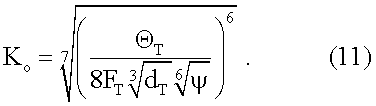
Используя выражение (11), находим допустимый объем твердой фазы (шлама, керна), поступающий в промывочную жидкость в единицу времени из зависимостиUsing expression (11), we find the allowable volume of the solid phase (sludge, core) entering the flushing fluid per unit time from the dependence
![]()
![]()
где Θ - максимально допустимый объем твердой фазы;where Θ is the maximum permissible volume of the solid phase;
Q - расход промывочной жидкости;Q is the flow rate of flushing fluid;
Кo - критическая концентрация твердой фазы.To o is the critical concentration of the solid phase.
Этот же объем твердой фазы, образуемый при бурении скважины с гидротранспортом керна, может быть определен по формуле Ю.Е.Будюкова, В.И.Власюка, В.И.Спирина (см. Ю.Е.Будюков, В.И.Власюк, В.И.Спирин. Алмазный породоразрушающий инструмент.- Тула: ИПП «Гриф и К», 2005. - 288 с.).The same volume of the solid phase formed during drilling of a well with hydrotransport of the core can be determined by the formula of Yu.E. Budyukov, V.I. Vlasyuk, V.I. Spirin (see Yu.E. Budyukov, V.I. Vlasyuk , V.I. Spirin, Diamond rock-cutting tool.- Tula: IPP “Grif and K”, 2005. - 288 p.).
![]()
![]()
где F3 - площадь забоя скважины;where F 3 is the bottom hole area;
VM - скорость углубки скважины.V M is the velocity of the wellbore.
Допустимую концентрацию твердой фазы в промывочной жидкости поддерживают регулированием ее расхода, изменением осевой нагрузки на инструмент, изменением частоты вращения бурового снаряда или их одновременном регулировании в различных сочетаниях.The permissible concentration of the solid phase in the flushing fluid is supported by adjusting its flow rate, changing the axial load on the tool, changing the rotational speed of the drill or adjusting them simultaneously in various combinations.
Допустимую концентрацию твердой фазы в промывочной жидкости наиболее просто поддерживают за счет увеличения ее расхода при промывке скважины с расходом, определенным по зависимостям (11), (12), не менееThe permissible concentration of the solid phase in the washing liquid is most simply supported by increasing its flow rate when flushing the well with a flow rate determined by dependences (11), (12), not less than
![]()
![]()
где QKP - минимально допустимый расход промывочной жидкости исходя из условия предупреждения шламонакопления и пробкообразования в колонковых и бурильных трубах при бурении.where Q KP is the minimum allowable flow rate of flushing fluid based on the conditions for preventing sludge accumulation and corking in core and drill pipes during drilling.
Не всегда мощность насосного оборудования позволяет увеличить расход промывочной жидкости до значения QKP, особенно при больших диаметрах бурения, в этом случае другим путем, позволяющим уменьшить концентрацию твердой фазы в промывочной жидкости до допустимых значений, является снижение скорости углубки.Not always the power of the pumping equipment allows to increase the flow rate of the flushing fluid to the value of Q KP , especially with large drilling diameters, in this case, another way to reduce the concentration of the solid phase in the flushing fluid to acceptable values is to reduce the speed of the recess.
Максимально допустимая механическая скорость бурения с гидротранспортом керна с фиксированным расходом промывочной жидкости составлена с учетом (11), (12).The maximum allowable mechanical drilling speed with core hydrotransport with a fixed flow rate of flushing fluid was compiled taking into account (11), (12).
![]()
![]()
где ![]()
![]()
Q - расход промывочной жидкости.Q - flow rate of flushing fluid.
С учетом (11) запишем формулу (15) в видеIn view of (11), we write formula (15) in the form

Установлено (см. Ю.Е.Будюков. Создание и производство специального алмазного бурового инструмента. - М., МГП «Геоинформмарк», 1993), что скорость углубки является в основном функцией осевой нагрузки на инструмент и частоты его вращения и имеет видIt has been established (see Yu.E. Budyukov. Creation and production of a special diamond drilling tool. - M., MGP Geoinformmark, 1993) that the velocity of a recess is mainly a function of the axial load on the tool and its rotation frequency and has the form
![]()
![]()
где VM - скорость углубки скважины,where V M is the velocity of the wellbore,
![]()
![]()
где Lk - постоянный коэффициент;where L k is a constant coefficient;
PШ - твердость горной породы по штампу;P W - rock hardness by stamp;
Dc - диаметр коронки по ее среднему радиусу;D c - the diameter of the crown in its average radius;
n - частота вращения снаряда;n is the rotational speed of the projectile;
P - осевая нагрузка на инструмент.P - axial load on the tool.
Поэтому допустимую концентрацию твердой фазы в промывочной жидкости при значительном возрастании скорости углубки (например, при входе коронки в мягкие породы) можно поддерживать путем регулирования осевой нагрузки на инструмент и частоты его вращения, при которых критическая механическая скорость углубки бурения ![]()
![]()
Вследствие того, что при бурении керн разделяется на столбики, длина которых определяется по зависимостиDue to the fact that during drilling, the core is divided into columns, the length of which is determined by the dependence
![]()
![]()
где h - длина столбика керна;where h is the length of the core column;
К1 - опытный коэффициент (К1=0,7÷1,0);K 1 - experimental coefficient (K 1 = 0.7 ÷ 1.0);
dk - диаметр керна;d k is the core diameter;
R, r - наружный и внутренний радиусы отверстия трубы сальника,R, r - the outer and inner radii of the openings of the stuffing box pipe,
соответственно создаются условия для свободного прохождения керна в бурильных трубах и керноотвода сальника, и, благодаря этому, исключается образование пробок керна на забое скважины и возникновение подклинок керна в бурильных трубах.accordingly, conditions are created for the free passage of the core in the drill pipes and core removal of the stuffing box, and this prevents the formation of core plugs at the bottom of the well and the occurrence of core sticks in the drill pipes.
Благодаря тому, что кернолом расположен в корпусе алмазного расширителя так, что расстояние от середины его длины до торца алмазной коронки определяется из соотношенияDue to the fact that the core is located in the body of the diamond expander so that the distance from the middle of its length to the end of the diamond crown is determined from the ratio
l=k2h,l = k 2 h,
где l - расстояние от середины длины кернолома до торца алмазной коронки;where l is the distance from the middle of the length of the kernel to the end of the diamond crown;
k2 - опытный коэффициент (k2=0,80÷1,00);k 2 is the experimental coefficient (k 2 = 0.80 ÷ 1.00);
h - задняя длина столбика керна,h is the rear length of the core column,
при этом износостойкость материала кернолома выше, чем износостойкость материала корпуса расширителя в процессе бурения, выбуренный керн, достигая кернолома, установленного на определенном расстоянии «l» от торца коронки, скалывается на примерно одинаковые столбики с заранее заданной длиной не более h и выносится на поверхность восходящим потоком очистного агента, что способствует формированию равномерной скорости гидротранспорта шлама и керна и устранению подклинок керна в бурильных трубах.in this case, the wear resistance of the core material is higher than the wear resistance of the material of the expander body during drilling, when the core is drilled, reaching the core core installed at a certain distance “l” from the end face of the core, it breaks into approximately identical columns with a predetermined length of no more than h and is brought up to the surface the flow of the cleaning agent, which contributes to the formation of a uniform speed of hydraulic transport of sludge and core and the elimination of core sticks in the drill pipe.
Вследствие того, что суммарная площадь поперечных сечений промывочных каналов расширителя, суммарная площадь поперечных сечений наружных боковых каналов алмазной коронки, суммарная площадь продольного сечения ее торцевых каналов и суммарная площадь поперечных сечений внутренних боковых каналов находятся в соотношенииDue to the fact that the total cross-sectional area of the flushing channels of the expander, the total cross-sectional area of the outer side channels of the diamond crown, the total longitudinal sectional area of its end channels and the total cross-sectional area of the inner side channels are in the ratio
SP:SH:ST:Sв=1,00:1,10:1,15:1,20 S P: S H: S T : S B = 1.00: 1.10: 1.15: 1.20
где SP, SH, Sв - суммарная площадь поперечных сечений промывочных каналов расширителя, наружных боковых каналов коронки и внутренних боковых каналов коронки соответственно;where S P , S H, S in - the total cross-sectional area of the washing channels of the expander, the outer side channels of the crown and the inner side channels of the crown, respectively;
ST - суммарная площадь продольного сечения торцевых промывочных каналов коронки.S T is the total longitudinal sectional area of the end flushing channels of the crown.
Уменьшаются возникающие при обратной промывке (в отличие от прямой промывки) высокие гидравлические сопротивления за счет содержания в жидкости породного шлама во всех элементах бурового снаряда: расширителе, коронке, колонковой трубе и бурильных трубах.High hydraulic resistance arising from backwashing (as opposed to direct flushing) is reduced due to the presence of rock cuttings in the fluid in all elements of the drill string: expander, crown, core pipe and drill pipes.
Причем соотношение суммарных площадей поперечных сечений промывочных каналов расширителя и суммарных площадей поперечных сечений наружного, внутреннего бокового каналов алмазной коронки и суммарной площади продольного сечения ее торцевых каналов в пропорции SP:SH:ST:Sв=1,00:1,10:1,15:1,20 является оптимальным, т.к. при более высоких значениях соотношений сопротивления снижаются незначительно, и при более низких значениях соотношений гидравлические сопротивления возрастают.Wherein the ratio of the total cross-sectional areas flushing channel extender and the total cross-sectional areas of the outer, the inner side of the diamond crown and the total area of channel cross-section of the longitudinal channels in its end proportions S P: S H: S T : S = 1.00 to 1.10 : 1.15: 1.20 is optimal because at higher values of the ratio of the resistance decreases slightly, and at lower values of the ratio of hydraulic resistance increase.
При такой конструкции промывочной системы расширителя и коронки обеспечивается повышение эффекта нижней промывки за счет возможности струи жидкости расширяться (при прохождении ее из наружного бокового канала в торцевой канал) в поперечном размере путем присоединения масс окружающей жидкости, что обуславливает хороший обмыв забоя, взвешивание и удаление выбуренной породы и, как следствие, повышение механической скорости бурения. При этом происходит формирование примерно одинаковых по величине скоростей (не превышающих определенного критического значения), нисходящего и восходящего потоков, что способствует возникновению ламинарного движения жидкости и существенному уменьшению разрушения стенок скважины и потери промывочной жидкости вследствие утечки ее в поглощающие горные породы на забое.With this design of the flushing system of the expander and crown, the effect of the lower flushing is enhanced due to the ability of the liquid stream to expand (when passing from the outer side channel to the end channel) in the transverse dimension by adding masses of the surrounding liquid, which leads to good washing of the bottom, weighing and removal of the drilled hole rocks and, as a result, increased mechanical drilling speed. In this case, the formation of approximately the same velocity (not exceeding a certain critical value), downward and upward flows, which contributes to the appearance of laminar fluid movement and a significant reduction in the destruction of the walls of the well and loss of flushing fluid due to its leakage into absorbing rocks at the bottom.
Указанное способствует поддержанию ствола скважины в состоянии, пригодном для бесперебойного его углубления без зашламования и пробкообразования до проектной глубины.The above contributes to maintaining the wellbore in a condition suitable for uninterrupted deepening without slamming and plugging to the design depth.
На фиг.1 приведена схема бурения с гидротранспортом керна, которая включает расположение следующего оборудования и инструмента: алмазная буровая коронка 1, алмазный расширитель 15, колонковая труба 2, керн 3, отстойник 4, насос 5, привентор 6, укрепленный на обсадной трубе 13, вращатель бурового станка 7, сальник 8, отводная труба 9, желоб 10, тройник 11, бурильная труба 12, пакер 14.Figure 1 shows a drilling pattern with hydraulic core transport, which includes the location of the following equipment and tools: diamond drill bit 1,
На фиг.2 показан одинарный буровой снаряд (продольный разрез) для бурения с гидротранспортом керна, включающий: алмазную буровую коронку 1 с боковыми наружными промывочными каналами 2, торцевыми промывочными каналами 3 и боковыми внутренними каналами 4, расширитель 5 с керноломом 6, бурильную (колонковую) трубу 7, внутри которой находится столбик керна 8.Figure 2 shows a single drill bit (longitudinal section) for drilling with core hydrotransport, including: a diamond drill bit 1 with side
Способ бурения реализуется следующим образом.The drilling method is implemented as follows.
Промывочная жидкость из отстойника 4 насосом 5 через тройник 11, расположенный на обсадной трубе 13 ниже привентора 6, подается в затрубное пространство вначале между стенками обсадной трубы 13 и бурильными трубами 12, а затем между стенками скважины и бурильными трубами 12, колонковой трубой 2 и расширителем 15 поступает под рабочий торец алмазной коронки 1 через ее промывочные каналы: боковые наружные 2, внутренние 4 и торцевые 3, при этом струя жидкости расширяется в поперечных размерах путем присоединения масс окружающей жидкости, обуславливая хороший обмыв забоя со взвешиванием и удалением выбуренной породы и способствуя уменьшению сопротивления поступления породы в центральные каналы и расходу осевой нагрузки в большой степени на деформацию породы. Далее промывочная жидкость попадает в коронку 1, омывает керн 8 и после скалывания его керноломом 6 примерно на равные по длине столбики выносит их при равномерной скорости восходящего потока внутри бурильных труб 12 через отводную трубу 9 сальника 8 в желоб 10, за керном следует вынос шлама. Так происходит бесперебойное углубление ствола скважины при высокой производительности без зашламования и пробкообразования до проектной глубины.Flushing fluid from the
Данное изобретение может быть осуществлено при помощи описанных в заявке средств. Оно было внедрено в геологоразведочной экспедиции «БУРЯТЗОЛОТОРАЗВЕДКА».This invention can be carried out using the means described in the application. It was introduced in the exploration expedition “Buryatzolotorazvedka”.
Технико-экономическая эффективность предлагаемого изобретения заключается в повышении производительности бурения и снижения себестоимости на 150 руб. на 1 м бурения.Feasibility study of the present invention is to increase drilling productivity and reduce costs by 150 rubles. per 1 m of drilling.
Claims (2)

где Wкр - критическая скорость восходящего потока;
F3 - площадь забоя;
VM - скорость углубки скважины;
FT - площадь поперечного сечения внутреннего канала бурильной трубы;
γn - удельный вес частиц породы;
γ - удельный вес промывочной жидкости, закачиваемой в скважину;
γT - удельный вес промывочной жидкости в бурильных трубах;
λ - коэффициент, учитывающий винтообразное движение частиц (λ=1,25-1,27);
а - опытный коэффициент, определяемый по методике А.С.Денисова (а=1,14);
k - опытный коэффициент, зависящий от формы частиц и закона обтекания потоком, определяемый по методике Ф.А.Шамшева (для шара k=5,11);
dn - диаметр частицы,
и скорость углубки поддерживают не более критической величины

где VМkр - критическая скорость углубки скважины;
F3 - площадь забоя скважины;
Q - расход промывочной жидкости;
QT - расход твердой фазы;
FT - площадь поперечного сечения внутреннего канала бурильных труб;
dT - диаметр внутреннего канала бурильных труб;
ψ - опытный коэффициент, определяемый по методике Р.Р.Чугаева (ψ=2,0),
при этом керн при бурении разделяется на столбики, длина которых определяется по зависимости
где h - длина столбика керна;
K1 - опытный коэффициент (K1=0,7÷1,0);
dk - диаметр керна;
R, r - наружный и внутренний радиусы отверстия отводной трубы сальника соответственно.1. A method of drilling hard rocks with core hydrotransport, including rock destruction, core formation, column breaking, core and sludge removal by an upward flow of drilling fluid through the internal channel of a single drill pipe string to the surface, and adjustment of the velocity of the wellbore by changing the axial load on drilling tool, its rotation frequency and flow rate of flushing fluid separately or in combination, characterized in that at the beginning of drilling, the critical velocity ascending eye wash fluid from the following relation:
where W kr is the critical velocity of the upward flow;
F 3 - the area of the face;
V M is the velocity of the wellbore;
F T is the cross-sectional area of the inner channel of the drill pipe;
γ n is the specific gravity of the rock particles;
γ is the specific gravity of the flushing fluid injected into the well;
γ T is the specific gravity of drilling fluid in drill pipes;
λ is a coefficient taking into account the helical motion of particles (λ = 1.25-1.27);
a - experimental coefficient, determined by the method of A.S. Denisov (a = 1.14);
k is the experimental coefficient, depending on the shape of the particles and the law of flow around the stream, determined by the method of F. A. Shamshev (for the ball, k = 5.11);
d n is the particle diameter,
and the velocity of the recess support no more than a critical value
where V Mkr is the critical velocity of the wellbore;
F 3 - bottom hole area;
Q is the flow rate of flushing fluid;
Q T is the flow rate of the solid phase;
F T is the cross-sectional area of the inner channel of the drill pipe;
d T is the diameter of the inner channel of the drill pipe;
ψ is the experimental coefficient determined by the method of R.R. Chugaev (ψ = 2.0),
while the core during drilling is divided into columns, the length of which is determined by the dependence
where h is the length of the core column;
K 1 - experimental coefficient (K 1 = 0.7 ÷ 1.0);
d k is the core diameter;
R, r are the outer and inner radii of the openings of the outlet pipe of the gland, respectively.
l=k2h,
где l - расстояние от середины длины кернолома до торца алмазной коронки;
k2 - опытный коэффициент (k2=0,80÷1,00);
h - задняя длина столбика керна,
при этом износостойкость материала кернолома выше, чем износостойкость материала корпуса расширителя, а суммарная площадь поперечных сечений промывочных каналов расширителя, суммарная площадь поперечных сечений наружных боковых каналов алмазной коронки, суммарная площадь продольного сечения ее торцевых каналов и суммарная площадь поперечных сечений внутренних боковых каналов находятся в соотношении
SP:SH:ST:Sв=1,00:1,10:1,15:1,20,
где SP, SH Sв - суммарная площадь поперечных сечений промывочных каналов расширителя, наружных боковых каналов коронки и внутренних боковых каналов коронки соответственно;
ST - суммарная площадь продольного сечения торцевых промывочных каналов коронки. 2. A drill for drilling hard rock with core hydrotransport, including drill pipes, core pipe, diamond reamer, core drill and diamond drill bit, characterized in that the core drill is located in the diamond reamer body so that the distance from the middle of its length to the end face of the diamond core determined from the relation
l = k 2 h,
where l is the distance from the middle of the length of the kernel to the end of the diamond crown;
k 2 is the experimental coefficient (k 2 = 0.80 ÷ 1.00);
h is the rear length of the core column,
the wear resistance of the core material is higher than the wear resistance of the material of the expander body, and the total cross-sectional area of the flushing channels of the expander, the total cross-sectional area of the outer side channels of the diamond crown, the total longitudinal section of its end channels and the total cross-sectional area of the inner side channels are in the ratio
S P: S H: S T : S B = 1.00: 1.10: 1.15: 1.20,
where S P , S H S in - the total cross-sectional area of the washing channels of the expander, the outer side channels of the crown and the inner side channels of the crown, respectively;
S T is the total longitudinal sectional area of the end flushing channels of the crown.
Priority Applications (1)
| Application Number | Priority Date | Filing Date | Title |
|---|---|---|---|
| RU2007147527/03A RU2386005C2 (en) | 2007-12-19 | 2007-12-19 | Drilling method of hard rocks with hydrotransport of core sample and drilling assembly for its implementation |
Applications Claiming Priority (1)
| Application Number | Priority Date | Filing Date | Title |
|---|---|---|---|
| RU2007147527/03A RU2386005C2 (en) | 2007-12-19 | 2007-12-19 | Drilling method of hard rocks with hydrotransport of core sample and drilling assembly for its implementation |
Publications (2)
| Publication Number | Publication Date |
|---|---|
| RU2007147527A RU2007147527A (en) | 2009-06-27 |
| RU2386005C2 true RU2386005C2 (en) | 2010-04-10 |
Family
ID=41026678
Family Applications (1)
| Application Number | Title | Priority Date | Filing Date |
|---|---|---|---|
| RU2007147527/03A RU2386005C2 (en) | 2007-12-19 | 2007-12-19 | Drilling method of hard rocks with hydrotransport of core sample and drilling assembly for its implementation |
Country Status (1)
| Country | Link |
|---|---|
| RU (1) | RU2386005C2 (en) |
Cited By (1)
| Publication number | Priority date | Publication date | Assignee | Title |
|---|---|---|---|---|
| RU2499887C1 (en) * | 2012-03-26 | 2013-11-27 | Федеральное государственное бюджетное образовательное учреждение высшего профессионального образования "Уфимский государственный нефтяной технический университет" | Adaptive control method of well drilling conditions, and bit for its implementation |
Families Citing this family (1)
| Publication number | Priority date | Publication date | Assignee | Title |
|---|---|---|---|---|
| CN114086950B (en) * | 2021-10-21 | 2023-03-10 | 航天凯天环保科技股份有限公司 | Geological exploration sampling method |
-
2007
- 2007-12-19 RU RU2007147527/03A patent/RU2386005C2/en not_active IP Right Cessation
Non-Patent Citations (1)
| Title |
|---|
| КУЗЬМИН И.В. и др. Методические рекомендации по бурению скважин с выносом керна обратным потоком промывочной жидкости. - М.: НПО "ГЕОТЕХНИКА" СКБ, 1977, с.25-42. * |
Cited By (1)
| Publication number | Priority date | Publication date | Assignee | Title |
|---|---|---|---|---|
| RU2499887C1 (en) * | 2012-03-26 | 2013-11-27 | Федеральное государственное бюджетное образовательное учреждение высшего профессионального образования "Уфимский государственный нефтяной технический университет" | Adaptive control method of well drilling conditions, and bit for its implementation |
Also Published As
| Publication number | Publication date |
|---|---|
| RU2007147527A (en) | 2009-06-27 |
Similar Documents
| Publication | Publication Date | Title |
|---|---|---|
| CN109653691B (en) | Hydraulic and mechanical compound controllable rock debris bed cleaning tool | |
| RU2469173C2 (en) | Well drilling bit, and drilling method | |
| CN201087704Y (en) | Drilling tool stabilizer for gas drilling | |
| CN104141464B (en) | Horizontal well borehole cleaning tool | |
| CN106062299A (en) | Multi fluid drilling system | |
| WO2003042485A2 (en) | Apparatus for extraction of oil via underground drilling and production location | |
| CN108678679B (en) | A kind of sea bed gas hydrate layer composite drill bit | |
| US6311791B1 (en) | Hydraulic underreamer and sections for use therein | |
| WO1991017339A1 (en) | Method and apparatus for drilling and coring | |
| RU2386005C2 (en) | Drilling method of hard rocks with hydrotransport of core sample and drilling assembly for its implementation | |
| RU166522U1 (en) | DRILLING DRILL FOR DRILLING WITH SIMULTANEOUS CASE | |
| RU2717167C1 (en) | Well bottomhole washing method | |
| RU138113U1 (en) | CHISEL WITH ADVANCED BLADES | |
| RU109496U1 (en) | DEVICE FOR CLEANING WELLS FROM Sludge | |
| US6223839B1 (en) | Hydraulic underreamer and sections for use therein | |
| US11180959B2 (en) | Wellbore drill bit | |
| RU2710577C1 (en) | Method of installing a cement plug for driving unstable rocks when drilling a well | |
| RU2190089C1 (en) | Process of deep perforation of cased wells | |
| KR101194389B1 (en) | Fluid drive type drill beat assembly and drilling machine | |
| RU2435925C1 (en) | Procedure for construction of horizontal drain hole in unstable moveable rock and drilling assembly for its implementation | |
| Verisokin et al. | Device for removing proppant deposits formed in wells after hydraulic fracturing | |
| RU2436928C1 (en) | Bladed calibrator | |
| RU201798U1 (en) | SPREADING TOOL | |
| RU2779682C1 (en) | Casing reamer bit | |
| RU61773U1 (en) | DRILLING HYDROMECHANICAL DRILL |
Legal Events
| Date | Code | Title | Description |
|---|---|---|---|
| MM4A | The patent is invalid due to non-payment of fees |
Effective date: 20101220 |