RU2380304C2 - Device to feed and withdraw vessels - Google Patents
Device to feed and withdraw vessels Download PDFInfo
- Publication number
- RU2380304C2 RU2380304C2 RU2004132575/11A RU2004132575A RU2380304C2 RU 2380304 C2 RU2380304 C2 RU 2380304C2 RU 2004132575/11 A RU2004132575/11 A RU 2004132575/11A RU 2004132575 A RU2004132575 A RU 2004132575A RU 2380304 C2 RU2380304 C2 RU 2380304C2
- Authority
- RU
- Russia
- Prior art keywords
- containers
- sprocket
- center
- side surfaces
- possibility
- Prior art date
Links
Images

Classifications
-
- B—PERFORMING OPERATIONS; TRANSPORTING
- B65—CONVEYING; PACKING; STORING; HANDLING THIN OR FILAMENTARY MATERIAL
- B65G—TRANSPORT OR STORAGE DEVICES, e.g. CONVEYORS FOR LOADING OR TIPPING, SHOP CONVEYOR SYSTEMS OR PNEUMATIC TUBE CONVEYORS
- B65G47/00—Article or material-handling devices associated with conveyors; Methods employing such devices
- B65G47/74—Feeding, transfer, or discharging devices of particular kinds or types
- B65G47/84—Star-shaped wheels or devices having endless travelling belts or chains, the wheels or devices being equipped with article-engaging elements
- B65G47/846—Star-shaped wheels or wheels equipped with article-engaging elements
-
- B—PERFORMING OPERATIONS; TRANSPORTING
- B65—CONVEYING; PACKING; STORING; HANDLING THIN OR FILAMENTARY MATERIAL
- B65G—TRANSPORT OR STORAGE DEVICES, e.g. CONVEYORS FOR LOADING OR TIPPING, SHOP CONVEYOR SYSTEMS OR PNEUMATIC TUBE CONVEYORS
- B65G2201/00—Indexing codes relating to handling devices, e.g. conveyors, characterised by the type of product or load being conveyed or handled
- B65G2201/02—Articles
- B65G2201/0235—Containers
- B65G2201/0244—Bottles
Landscapes
- Engineering & Computer Science (AREA)
- Mechanical Engineering (AREA)
- Specific Conveyance Elements (AREA)
- Filling Of Jars Or Cans And Processes For Cleaning And Sealing Jars (AREA)
- Attitude Control For Articles On Conveyors (AREA)
- Supplying Of Containers To The Packaging Station (AREA)
- Control And Other Processes For Unpacking Of Materials (AREA)
- Feeding Of Articles To Conveyors (AREA)
- Cleaning In General (AREA)
Abstract
Description
Изобретение относится к устройству для подачи и отводу емкостей, в частности для подачи бочек, банок и пр. с ленточного транспортера на линейный транспортер или карусельный стол, а также для подачи таких емкостей на отводящий транспортер со звездочкой согласно ограничительной части п.1 формулы изобретения.The invention relates to a device for feeding and discharging containers, in particular for supplying barrels, cans, etc. from a conveyor belt to a linear conveyor or carousel table, and also for feeding such containers to a discharge conveyor with an asterisk according to the preamble of
Такие устройства применяются, например, в машинах для обработки емкостей. К обрабатывающей машине вертикально установленные и выравненные емкости подаются ленточным транспортером, при этом их загрузка и выгрузка производится посредством соответствующей звездочки. Загрузочная звездочка подает емкости на карусельный стол машины, а разгрузочная звездочка отбирает обработанные емкости из машины и перемещает их на движущийся около нее отводящий ленточный транспортер.Such devices are used, for example, in machines for processing containers. Vertically installed and leveled containers are fed to the processing machine by a conveyor belt, while their loading and unloading is carried out by means of the corresponding asterisk. The loading sprocket feeds the containers to the carousel table of the machine, and the unloading sprocket picks up the processed containers from the machine and moves them to the discharge conveyor belt moving near it.
Устройства такого типа применяются также и для других цилиндрических емкостей и в других машинах, например в разливочных и этикетировочных машинах, инспекционных и испытательных машинах, бочкоразливочных машинах и пр. При этом принято применять для каждого диаметра емкости отдельный комплект звездочек.Devices of this type are also used for other cylindrical containers and in other machines, for example, in filling and labeling machines, inspection and testing machines, barrel filling machines, etc. Moreover, it is customary to use a separate set of sprockets for each container diameter.
Также известно, что подобные устройства содержат две, жестко связанные между собой соосные звездочки, одна из боковых поверхностей рычагов которых образует задний упор для перемещаемых емкостей, что между этими звездочками располагается средняя, соосная звездочка, боковые поверхности рычагов которой, противолежащие боковым поверхностям других зубьев, образуют передний упор для емкостей, и что предусмотрены средства для разворота средней звездочки по отношению к паре звездочек на установочный угол таким образом, чтобы устройство могло приводиться в соответствие с разными диаметрами емкостей.It is also known that such devices contain two coaxial sprockets that are rigidly connected to each other, one of the side surfaces of the levers of which forms a back stop for movable containers, that between these stars there is a middle, coaxial sprocket, the side surfaces of the levers of which are opposite to the side surfaces of other teeth, form a front stop for containers, and that means are provided for turning the middle sprocket with respect to a pair of sprockets by a set angle so that the device can brought into line with the different diameters of containers.
Исходя из этого уровня техники, в основу изобретения положена задача создания устройства для подачи и/или отвода разных емкостей, в котором можно отказаться от применения настраиваемых и/или переналаживаемых элементов звездочки, а также от разворачиваемых по отношению друг к другу плоскостей карманов звездочек.Based on this prior art, the invention is based on the task of creating a device for supplying and / or withdrawing various containers, in which it is possible to refuse to use customizable and / or readjustable sprocket elements, as well as planes of sprocket pockets deployed relative to each other.
Указанная задача решается в устройстве согласно ограничительной части п.1 формулы изобретения в результате того, что толкающие и/или центрирующие боковые поверхности звездочки приводятся в действие автоматически и в положении вращения могут настраиваться на разные диаметры емкостей в результате вращательного смещения по отношению к центру емкости, соответственно диаметру корпуса емкости и соответствующему положению в машине.This problem is solved in the device according to the restrictive part of
При этом в качестве отдельного варианта предлагается, чтобы толкающие и/или центрирующие боковые поверхности звездочки могли управляться с опережением или запаздыванием и/или приводиться в положение толкания на неполную величину смещения центра соответствующих емкостей разных диаметров.Moreover, as a separate option, it is proposed that the pushing and / or centering lateral surfaces of the sprocket could be controlled ahead or delayed and / or brought into the pushing position by an incomplete shift of the center of the corresponding containers of different diameters.
Благодаря этому варианту при автономном приводе звездочки становится возможным любое относительное позиционирование и, следовательно, отдельное приведение в соответствие с разными диаметрами емкостей без необходимости механических и прочих регулировок подводящей и/или отводящей звездочки. Переналадка достигается настройкой на соответствующий размер обрабатываемой емкости, причем с помощью синхронных, серво-, шаговых и других приводных электродвигателей и соответствующих управляющих и/или контрольных модулей, таких, например, как сельсин-датчик, управляющая карта, ПК, программное обеспечение и пр., автоматически обеспечивается синхронное в отношении угла поворота и скорости позиционирование боковых поверхностей звездочки или самой звездочки и точное расположение емкостей в требуемом передаточном положении.Thanks to this option, with the independent drive of the sprocket, any relative positioning becomes possible and, therefore, a separate adjustment to different diameters of the tanks without the need for mechanical and other adjustments of the feed and / or discharge sprockets. The readjustment is achieved by adjusting to the appropriate size of the processed tank, with the help of synchronous, servo, step and other drive motors and the corresponding control and / or control modules, such as, for example, selsyn sensor, control card, PC, software, etc. The positioning of the lateral surfaces of the sprocket or the sprocket itself and the exact location of the tanks in the desired gear position are automatically ensured in synchronization with respect to the rotation angle and speed.
Ниже изобретение поясняется с помощью упрощенного примера осуществления, при котором емкость подается в обрабатывающую машину. Соответствующие аналогичные приемы обеспечивают условия и процессы при передаче такой емкости из обрабатывающей машины на расположенный на стороне выгрузки отводящий транспортер.The invention is explained below with a simplified embodiment in which a container is supplied to a processing machine. Appropriate similar techniques provide the conditions and processes for transferring such a tank from a processing machine to a discharge conveyor located on the discharge side.
При этом изображено на:It is depicted on:
фиг.1 - линейная обрабатывающая машина,figure 1 - linear processing machine,
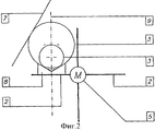
фиг.2 - передаточная звездочка призматической конструкции.figure 2 - gear sprocket prismatic design.
Устройство для подачи и отвода емкостей состоит в основном из вращающейся звездочки 1 с приемными карманами, боковыми поверхностями 2 или призмами 8, к которым прилегает наружной поверхностью 3 емкость во время передачи. Карманы звездочки или боковые поверхности 2 располагаются предпочтительно парно на разных уровнях с наличием соответствующего промежутка между ними и приводятся в действие автономным, независимым от привода машины приводным устройством 5. Для этой цели могут применяться синхронные, шаговые, серво- и другие соответствующие электродвигатели, которые в зависимости от выбора могут приводиться в действие и управляться с обеспечением синхронности скорости, положения и/или угла поворота.The device for supplying and removing containers consists mainly of a rotating
Учитывая, что устройство приводится в действие, по меньшей мере, одним автономным приводным двигателем и механически не связано с органами собственно машины для обработки емкостей, совершающими приводные и/или вращательные движения, то предусмотрены средства, как, например, сельсин-датчик или указатель положения и пр., обеспечивающие соответствующее шагу зацепления положение и такое же приведение в действие устройства после прерывания работы и/или прекращения подачи электроэнергии.Considering that the device is driven by at least one self-contained drive motor and is not mechanically connected to the organs of the machine itself for processing containers, performing drive and / or rotational movements, means are provided, such as, for example, a selsyn sensor or a position indicator etc., providing the position corresponding to the engagement step and the same actuation of the device after interruption of operation and / or interruption of power supply.
Рабочее или толкающее положение боковых поверхностей или призм автоматически задается с учетом разных диаметров емкостей в результате вращательного смещения по отношению к диаметру емкости, соответственно его центру и требуемому положению емкости на опорной тарелке карусели, линейном транспортере или в положении обработки в машине. Круговое движение звездочки или боковых поверхностей 2 или призм 8 может происходить непрерывно, циклически или с шагом разной длины при ускорении и замедлении, причем целесообразно, чтобы в точке передачи обеспечивались преимущественно одинаковыми скорость движения емкостей 4 и скорость подачи или окружная скорость обрабатывающей машины. Между расположенными, например, с промежутком толкающими или центрирующими боковыми поверхностями 2 или призмами 8 предусмотрены, в зависимости от диаметра емкости, направляющие элементы 6, утапливаемые в соответствующем конечном положении. Они направляют емкость 4 в случае нарушения ее центрального положения к вращающейся опорной тарелке или в необходимую для обработки позицию. Такие направляющие элементы 6 могут не применяться в случае, когда емкости 4 подаются по центрирующей дорожке или транспортными устройствами с боковыми направляющими и когда используется дополнительная призматическая направляющая 8. В зависимости от скорости вращения направляющих элементов 6 для фиксации емкостей 4 могут применяться дополнительные прижимные или направляющие элементы 7. Согласно изображенному на фиг.2 примеру осуществления боковая поверхность или направляющий рычаг 2' снабжен призмой 8. При таком варианте осуществления емкости разного диаметра всегда передаются с соосным центрированием. На практике центральная ось 9 призмы всегда проходит через центр приемной плоскости, приемную опорную тарелку и пр. или такое прохождение может быть обеспечено. Призма 8 может быть расположена на боковой поверхности или направляющем рычаге 2 с возможностью смещения или подвижности с помощью двигателя для приведения в соответствие с разными центральными положениями. При использовании призмы 8 целесообразно оснастить ею все направляющие рычаги или боковые поверхности 2, 2'.The working or pushing position of the side surfaces or prisms is automatically set taking into account the different diameters of the containers as a result of rotational displacement with respect to the diameter of the container, its center and the required position of the container on the support plate of the carousel, linear conveyor or in the processing position in the machine. The circular movement of the sprocket or
Claims (12)
Applications Claiming Priority (3)
| Application Number | Priority Date | Filing Date | Title |
|---|---|---|---|
| DE10352885A DE10352885A1 (en) | 2003-11-10 | 2003-11-10 | Device for feeding and removing containers |
| DE10352885.7 | 2003-11-10 | ||
| DE10352885.7-22 | 2003-11-10 |
Publications (2)
| Publication Number | Publication Date |
|---|---|
| RU2004132575A RU2004132575A (en) | 2006-04-20 |
| RU2380304C2 true RU2380304C2 (en) | 2010-01-27 |
Family
ID=34428699
Family Applications (1)
| Application Number | Title | Priority Date | Filing Date |
|---|---|---|---|
| RU2004132575/11A RU2380304C2 (en) | 2003-11-10 | 2004-11-09 | Device to feed and withdraw vessels |
Country Status (9)
| Country | Link |
|---|---|
| US (3) | US20050121104A1 (en) |
| EP (1) | EP1529745B1 (en) |
| JP (1) | JP2005139003A (en) |
| AT (1) | ATE347524T1 (en) |
| DE (2) | DE10352885A1 (en) |
| ES (1) | ES2277185T3 (en) |
| PT (1) | PT1529745E (en) |
| RU (1) | RU2380304C2 (en) |
| UA (1) | UA87964C2 (en) |
Families Citing this family (13)
| Publication number | Priority date | Publication date | Assignee | Title |
|---|---|---|---|---|
| DE102008050249B4 (en) * | 2008-10-07 | 2011-04-14 | Khs Gmbh | Test method for checking an inspection device, which is designed as a label seat control device |
| US20130327793A1 (en) * | 2010-04-01 | 2013-12-12 | Khs Gmbh | Method of manufacturing and filling kegs with beer in a keg filling plant, which keg filling plant is disposed within a single building |
| KR101569603B1 (en) * | 2011-04-06 | 2015-11-16 | 미쯔비시 쥬우꼬오 쇼구힌호오소오기까이 가부시키가이샤 | Rotary-type filling machine and method for calculating filling quantity for rotary-type filling machine |
| DE102012101238A1 (en) * | 2012-02-16 | 2013-08-22 | Krones Ag | TRANSPORT DEVICE AND TRANSPORT PROCESS FOR TANK TREATMENT PLANT AND BLASTER |
| DE102013104082B4 (en) | 2013-04-23 | 2017-02-02 | Khs Gmbh | Transport device for containers |
| DE102013112434B3 (en) * | 2013-11-12 | 2014-09-25 | Khs Gmbh | Star wheel with adjustable star pockets - Nonius star |
| DE102013113292A1 (en) | 2013-12-02 | 2015-06-18 | Khs Gmbh | Transport star with adjustable star pockets |
| US9808114B1 (en) * | 2014-02-11 | 2017-11-07 | Steady Equipment Corporation | Automated machine for producing multiple cups of coffee |
| DE102016101985B4 (en) | 2016-02-04 | 2018-06-21 | Khs Gmbh | Transport star for guiding containers in a container treatment plant |
| NL2017196B1 (en) | 2016-07-20 | 2018-01-26 | Sluis Cigar Machinery Bv | Simulated cigarette parts reorienting apparatus |
| EP3409442B1 (en) * | 2017-06-02 | 2020-01-08 | Sidel Participations | Improved system and method for synchronization of a container forming machine and a container processing machine in a container processing plant |
| CN109132459B (en) * | 2018-10-29 | 2024-04-05 | 长沙开元仪器有限公司 | Bottle feeding device for coal sample bottles |
| CN109389769A (en) * | 2018-12-06 | 2019-02-26 | 东莞京川精密机械设备有限公司 | A kind of shared battery machine |
Family Cites Families (23)
| Publication number | Priority date | Publication date | Assignee | Title |
|---|---|---|---|---|
| GB1043868A (en) * | 1965-05-20 | 1966-09-28 | Wtz Feikeramischen Ind | Device for feeding round cross-sectional objects to or from a continuously operating machine |
| US4045940A (en) * | 1972-09-21 | 1977-09-06 | Filper Corporation | Baler system and method |
| US3905177A (en) * | 1973-10-29 | 1975-09-16 | Michael Herzog | Bottle capping machine |
| US3888065A (en) * | 1974-07-03 | 1975-06-10 | Raymond A Heisler | Apparatus and method for automatically positioning and inserting plastic plugs in a container top |
| EP0019405B1 (en) * | 1979-05-12 | 1983-09-28 | GKN Sankey Limited | Method of washing and filling containers |
| US4817363A (en) * | 1987-09-02 | 1989-04-04 | Owens-Illinois Plastic Products Inc. | Fitment inserter machine |
| DE3729324A1 (en) * | 1987-09-02 | 1989-03-16 | Henkel Kgaa | METHOD FOR SETTING PINS IN A TRAY AND DEVICE FOR CARRYING OUT THE METHOD |
| DE3833885A1 (en) * | 1988-10-05 | 1990-04-12 | Leifeld & Lemke Maschf | DEVICE FOR CLEANING AND FILLING CONTAINERS, ESPECIALLY BARRELS LIKE KEGS |
| GB8913434D0 (en) * | 1989-06-12 | 1989-08-02 | Ag Patents Ltd | Filling containers |
| EP0405402A3 (en) | 1989-06-26 | 1991-03-20 | Toyo Seikan Kaisha Limited | Aseptic filling machine |
| US5285528A (en) * | 1991-02-22 | 1994-02-08 | International Business Machines Corporation | Data structures and algorithms for managing lock states of addressable element ranges |
| IT1270504B (en) * | 1993-05-19 | 1997-05-06 | Simonazzi Spa | STAR CONVEYOR WITH ADJUSTMENT DEVICE FOR VARIOUS FORMAT CONTAINERS. |
| GB9418730D0 (en) * | 1994-09-16 | 1994-11-02 | Mead Corp | Adjustable metering device |
| DE19513064B4 (en) * | 1995-04-07 | 2004-04-01 | Khs Maschinen- Und Anlagenbau Ag | Method and system for filling containers with a liquid filling material and filling machine and labeling device for use in this method or system |
| CA2170956A1 (en) * | 1995-09-21 | 1997-03-22 | Joe F. Posge | Product filler head system with computer control |
| US6170232B1 (en) * | 1997-12-30 | 2001-01-09 | Vandegeijn Peter T. | Quick-change collet chuck |
| JP4237405B2 (en) * | 1998-03-09 | 2009-03-11 | シーマ・ラブス、インコーポレイテッド | Assembly |
| DE19814625A1 (en) * | 1998-04-01 | 1999-10-07 | Khs Masch & Anlagenbau Ag | Front table for vascular treatment machines |
| US6141943A (en) * | 1998-09-21 | 2000-11-07 | F. R. Drake Company | Food article loading head and method |
| DE10008426B4 (en) * | 2000-02-23 | 2011-07-28 | KHS GmbH, 44143 | System and method for filling containers with a liquid product |
| US6481188B1 (en) * | 2000-06-30 | 2002-11-19 | Owens Corning Fiberglas Technology, Inc. | Apparatus and method for sealing an article |
| DE10154203B4 (en) * | 2000-11-30 | 2004-05-27 | Ulrich Kremser | Inlet system for bottle processing machines in beverage and filling technology |
| DE10107004A1 (en) * | 2001-02-15 | 2002-09-12 | Langguth Gmbh & Co | Device for orientation of packing drum has rotatable centering stars on both sides of drum's transporting path and by points of their arms bear upon outer side of drum and by toothed belt drive revolve synchronously but contra-rotating |
-
2003
- 2003-11-10 DE DE10352885A patent/DE10352885A1/en not_active Ceased
-
2004
- 2004-10-27 ES ES04025469T patent/ES2277185T3/en active Active
- 2004-10-27 EP EP04025469A patent/EP1529745B1/en not_active Not-in-force
- 2004-10-27 PT PT04025469T patent/PT1529745E/en unknown
- 2004-10-27 DE DE502004002228T patent/DE502004002228D1/en active Active
- 2004-10-27 AT AT04025469T patent/ATE347524T1/en active
- 2004-11-05 JP JP2004321689A patent/JP2005139003A/en active Pending
- 2004-11-09 RU RU2004132575/11A patent/RU2380304C2/en not_active IP Right Cessation
- 2004-11-10 US US10/985,640 patent/US20050121104A1/en not_active Abandoned
- 2004-12-30 UA UA20041210975A patent/UA87964C2/en unknown
-
2008
- 2008-10-14 US US12/251,071 patent/US7779874B2/en not_active Expired - Fee Related
-
2010
- 2010-07-06 US US12/830,894 patent/US8297322B2/en not_active Expired - Fee Related
Also Published As
| Publication number | Publication date |
|---|---|
| ATE347524T1 (en) | 2006-12-15 |
| US8297322B2 (en) | 2012-10-30 |
| US20100269955A1 (en) | 2010-10-28 |
| DE10352885A1 (en) | 2005-07-07 |
| RU2004132575A (en) | 2006-04-20 |
| DE502004002228D1 (en) | 2007-01-18 |
| JP2005139003A (en) | 2005-06-02 |
| EP1529745A1 (en) | 2005-05-11 |
| US20050121104A1 (en) | 2005-06-09 |
| EP1529745B1 (en) | 2006-12-06 |
| PT1529745E (en) | 2007-02-28 |
| ES2277185T3 (en) | 2007-07-01 |
| US7779874B2 (en) | 2010-08-24 |
| US20090095371A1 (en) | 2009-04-16 |
| UA87964C2 (en) | 2009-09-10 |
Similar Documents
| Publication | Publication Date | Title |
|---|---|---|
| RU2380304C2 (en) | Device to feed and withdraw vessels | |
| KR920009297B1 (en) | Article hand-off apparatus | |
| EP2388082B1 (en) | Method and Apparatus for Container Recirculation | |
| KR100268365B1 (en) | Low speed container package forming machine | |
| CN102015463B (en) | A kind of method and apparatus for packing container to be sent to second unit from first module | |
| EP0927683A1 (en) | Apparatus for conveying, supplying, and filling unshaped containers, and method for conveying and supplying the same | |
| KR910007271B1 (en) | Method and apparatus for extracting individual parts from a conveyer | |
| US5096041A (en) | Method and apparatus for receiving and delivering articles with differing motion characteristics | |
| JP7385587B2 (en) | Continuous circulation container conveyor device in packaging machinery | |
| SA112330387B1 (en) | Transport device for work pieces having a longitudinal axis | |
| KR100702939B1 (en) | Shell transporting apparatus and shell transporting method using the same | |
| US5113636A (en) | Can lid feeder | |
| US3886353A (en) | Automatic continuous container inspecting method and apparatus | |
| US2801651A (en) | Filling structure | |
| CZ292525B6 (en) | Device for changing tools in a tool machine spindle | |
| CN115676334A (en) | Apparatus and method for buffering objects | |
| US1502201A (en) | Package-transferring machine | |
| US3136103A (en) | Machine for loading pineapple slices | |
| EP0348471A1 (en) | Straight line checkweigher | |
| JP2014108806A (en) | Container supply device, and container processing device having its container supply device | |
| EP1015321B1 (en) | Feeder mechanism and hopper for two different types of cartons | |
| SU921721A1 (en) | Automatic machine for measured-length cutting of tubes | |
| US3270859A (en) | Apparatus for handling bottles and similar containers | |
| JP2005119720A (en) | Cap seaming device | |
| KR100504327B1 (en) | Transfer apparatus and method for film bags |
Legal Events
| Date | Code | Title | Description |
|---|---|---|---|
| PD4A | Correction of name of patent owner | ||
| PD4A | Correction of name of patent owner | ||
| MM4A | The patent is invalid due to non-payment of fees |
Effective date: 20181110 |