RU2378080C2 - Die block for forging with marking facilities - Google Patents
Die block for forging with marking facilities Download PDFInfo
- Publication number
- RU2378080C2 RU2378080C2 RU2005108677/02A RU2005108677A RU2378080C2 RU 2378080 C2 RU2378080 C2 RU 2378080C2 RU 2005108677/02 A RU2005108677/02 A RU 2005108677/02A RU 2005108677 A RU2005108677 A RU 2005108677A RU 2378080 C2 RU2378080 C2 RU 2378080C2
- Authority
- RU
- Russia
- Prior art keywords
- dies
- stamp
- forging
- grooves
- marking
- Prior art date
Links
Images


Classifications
-
- B—PERFORMING OPERATIONS; TRANSPORTING
- B21—MECHANICAL METAL-WORKING WITHOUT ESSENTIALLY REMOVING MATERIAL; PUNCHING METAL
- B21J—FORGING; HAMMERING; PRESSING METAL; RIVETING; FORGE FURNACES
- B21J13/00—Details of machines for forging, pressing, or hammering
- B21J13/02—Dies or mountings therefor
-
- B—PERFORMING OPERATIONS; TRANSPORTING
- B21—MECHANICAL METAL-WORKING WITHOUT ESSENTIALLY REMOVING MATERIAL; PUNCHING METAL
- B21C—MANUFACTURE OF METAL SHEETS, WIRE, RODS, TUBES OR PROFILES, OTHERWISE THAN BY ROLLING; AUXILIARY OPERATIONS USED IN CONNECTION WITH METAL-WORKING WITHOUT ESSENTIALLY REMOVING MATERIAL
- B21C51/00—Measuring, gauging, indicating, counting, or marking devices specially adapted for use in the production or manipulation of material in accordance with subclasses B21B - B21F
- B21C51/005—Marking devices
-
- B—PERFORMING OPERATIONS; TRANSPORTING
- B21—MECHANICAL METAL-WORKING WITHOUT ESSENTIALLY REMOVING MATERIAL; PUNCHING METAL
- B21J—FORGING; HAMMERING; PRESSING METAL; RIVETING; FORGE FURNACES
- B21J9/00—Forging presses
- B21J9/10—Drives for forging presses
- B21J9/20—Control devices specially adapted to forging presses not restricted to one of the preceding subgroups
-
- B—PERFORMING OPERATIONS; TRANSPORTING
- B21—MECHANICAL METAL-WORKING WITHOUT ESSENTIALLY REMOVING MATERIAL; PUNCHING METAL
- B21K—MAKING FORGED OR PRESSED METAL PRODUCTS, e.g. HORSE-SHOES, RIVETS, BOLTS OR WHEELS
- B21K3/00—Making engine or like machine parts not covered by sub-groups of B21K1/00; Making propellers or the like
- B21K3/04—Making engine or like machine parts not covered by sub-groups of B21K1/00; Making propellers or the like blades, e.g. for turbines; Upsetting of blade roots
-
- B—PERFORMING OPERATIONS; TRANSPORTING
- B21—MECHANICAL METAL-WORKING WITHOUT ESSENTIALLY REMOVING MATERIAL; PUNCHING METAL
- B21K—MAKING FORGED OR PRESSED METAL PRODUCTS, e.g. HORSE-SHOES, RIVETS, BOLTS OR WHEELS
- B21K31/00—Control devices specially adapted for positioning tool carriers
-
- B—PERFORMING OPERATIONS; TRANSPORTING
- B21—MECHANICAL METAL-WORKING WITHOUT ESSENTIALLY REMOVING MATERIAL; PUNCHING METAL
- B21K—MAKING FORGED OR PRESSED METAL PRODUCTS, e.g. HORSE-SHOES, RIVETS, BOLTS OR WHEELS
- B21K5/00—Making tools or tool parts, e.g. pliers
- B21K5/20—Making working faces of dies, either recessed or outstanding
Abstract
Description
Настоящее изобретение касается области горячей объемной штамповки металлических деталей и, в частности, деталей сложной формы и искривленных деталей, например лопаток газотурбинного двигателя большого размера.The present invention relates to the field of hot die forging of metal parts and, in particular, parts of complex shape and curved parts, for example, large-sized gas turbine engine blades.
Технологии горячей объемной штамповки предпочтительно применяются для производства металлических деталей, когда в работе они должны испытывать большие напряжения. Это касается компрессора или лопастей вентилятора турбореактивных двигателей, в которых развиваются значительные внутренние напряжения от вибраций и центробежных сил, которым они подвергаются.Hot stamping techniques are preferably used for the production of metal parts when they must be subjected to high stresses during operation. This applies to the compressor or fan blades of turbojet engines, in which significant internal stresses develop from the vibrations and centrifugal forces to which they are subjected.
Горячая объемная штамповка состоит из пластической деформации металлического стержня под воздействием ударов или прикладываемого давления. В основном происходит поэтапное формование последовательных заготовок, которые постепенно доводятся до обработанной детали. При необходимости, штамповка детали завершается стадией калибровки, в результате которой получаются более точные формы.Hot stamping consists of plastic deformation of a metal rod under the influence of impacts or applied pressure. Basically, stage-by-stage formation of successive blanks takes place, which are gradually brought to the machined part. If necessary, stamping the part ends with a calibration stage, which results in more accurate shapes.
Более конкретно, деталь подвергают горячей объемной штамповке, воздействуя на заготовку последней ударом или давлением, при этом в штампе вырезан оттиск, соответствующий форме получаемой детали. В случае, если используется титан, поскольку его напряжение пластического течения сильно зависит от температуры, горячая объемная штамповка выполняется с подогревом до определенного предела, обусловленного структурным изменением в материале, определяющем его механические свойства.More specifically, the part is subjected to hot volumetric stamping, acting on the workpiece with the last blow or pressure, while a stamp corresponding to the shape of the obtained part is cut out in the stamp. In the case where titanium is used, since its plastic flow stress depends strongly on temperature, hot die forging is carried out with heating to a certain limit, due to a structural change in the material, which determines its mechanical properties.
Операции штамповки обычно выполняются на механических прессах с подогретыми штампами. В этих условиях время горячей объемной штамповки относительно непродолжительно для предотвращения слишком быстрого охлаждения детали и перегрева штампа вследствие теплопроводности между деталью и самим штампом, достигающей такой степени, что температура инструментов отличается от температуры детали. Кроме того, из-за высокого уровня напряжений, которому он подвергается от контакта с деталью, на вырезанный рельеф (гравировку) штампа накладывают смазывающее вещество, чтобы способствовать пластическому течению материала и уменьшить напряжение штамповки.Punching operations are usually performed on mechanical presses with heated dies. Under these conditions, the hot stamping time is relatively short to prevent the part from cooling too quickly and the stamp overheating due to thermal conductivity between the part and the stamp itself, reaching such an extent that the temperature of the tools differs from the temperature of the part. In addition, due to the high level of stresses to which it is subjected from contact with the part, a lubricant is applied to the cut relief (engraving) of the stamp to facilitate the plastic flow of the material and reduce the stamping stress.
Настоящее изобретение, прежде всего, касается регулировки инструментов, таких как штампы, представленные выше.The present invention primarily relates to the adjustment of tools, such as dies, presented above.
Изготовление детали согласно обычному способу занимает довольно продолжительное время, поскольку приходится приступать к последовательным операциям доводки.The manufacture of a part according to the usual method takes a rather long time, since it is necessary to proceed to sequential finishing operations.
Действительно, оттиск штампа не имеет точную форму и размеры необработанной штампуемой детали, которую следует получить. Он отличается от нее "пределами коррекции", которые компенсируют упругопластические деформации инструментов во время горячей объемной штамповки. Неизвестно, как предугадать эти пределы коррекции точно, и поэтому штамп нужно доводить согласно измерениям, выполненным на полученных деталях, прошедших испытания. В так называемой точной объемной штамповке допуски невелики, например 0,8 мм, так что обработанная деталь может быть получена полировкой необработанной детали абразивным ремнем или, если это нужно, особенно в случае титана, сочетанием химической обработки и полировки абразивным ремнем. Например, это относится к полотну лопастей.Indeed, the stamp imprint does not have the exact shape and dimensions of the untreated stamped part to be obtained. It differs from it by the “correction limits”, which compensate for the elastoplastic deformation of the instruments during hot forging. It is not known how to predict these correction limits accurately, and therefore the stamp must be adjusted according to the measurements made on the received parts that have passed the test. In the so-called precision die forging, tolerances are small, for example 0.8 mm, so that the machined part can be obtained by polishing the untreated part with an abrasive belt or, if necessary, especially in the case of titanium, a combination of chemical treatment and polishing with an abrasive belt. For example, this applies to the blade web.
Регулировка штампа точной объемной штамповки требует много времени и денежных затрат, поскольку она содержит множество операций доводки, которые отделены одна от другой испытаниями штампуемых деталей.Adjusting the die for precise volumetric stamping requires a lot of time and money, since it contains many finishing operations that are separated from one another by testing stamped parts.
Когда штамп отрегулирован, т.е. когда полученные штамповкой необработанные, прошедшие испытание детали имеют целевую форму и размеры, этот штамп может быть введен в работу для изготовления серийных деталей. Штамп постепенно разрушается в процессе своей работы и, например, после 1000-5000 деталей, как в данном случае, возникает необходимость в восстановлении штампа или использовании другого.When the stamp is adjusted, i.e. when stamped unprocessed, tested parts have a target shape and dimensions, this stamp can be put into operation for the manufacture of serial parts. The stamp is gradually destroyed during its work and, for example, after 1000-5000 parts, as in this case, the need arises to restore the stamp or use another one.
Восстановление разрушающегося штампа, согласно первому способу, заключается в восстановлении участков, где материал изношен, и в обработке и полировке нового оттиска, то есть переочистке штампа электроимпульсной обработкой. Согласно второму способу оттиск полностью подвергают повторному формованию обработкой после удаления слоя нитрида (с упрочением поверхности термической или термомеханической обработкой) и удаления материала толщиной в несколько миллиметров. Эта технология обозначена термином переочистка. Восстановление штампа или создание нового штампа требует такой же регулировки, как изначальный штамп. Поэтому они также требуют много времени и материальных затрат.The restoration of a collapsing stamp, according to the first method, consists in restoring the areas where the material is worn, and in processing and polishing a new print, that is, re-cleaning the stamp with electric pulse processing. According to the second method, the print is completely subjected to repeated molding by treatment after removal of the nitride layer (with hardening of the surface by thermal or thermomechanical processing) and removal of the material several millimeters thick. This technology is referred to as refining. Restoring a stamp or creating a new stamp requires the same adjustment as the original stamp. Therefore, they also require a lot of time and material costs.
Целью изобретения является создание средства для улучшения проверки совмещения штампов и для оптимизации времени регулировки при штамповке больших серий деталей.The aim of the invention is to provide means for improving the verification of alignment of the dies and to optimize the adjustment time when stamping large series of parts.
Согласно изобретению штамп для горячей объемной штамповки, включающий на одной поверхности половину оттиска штампуемой детали, такой как лопатка газотурбинного двигателя, характеризуется тем, что он имеет на указанной поверхности средство, образующее маркировку по двум направлениям, относительно которой определяется положение указанного оттиска, при этом указанное средство состоит из двух подушек, выступающих относительно указанной поверхности и включающих каждая две канавки, образующие указанные два направления.According to the invention, a stamp for hot volumetric stamping, including on one surface half the impression of the stamped part, such as a blade of a gas turbine engine, is characterized in that it has means on the surface to form a marking in two directions, relative to which the position of the specified print is determined, the tool consists of two pillows protruding relative to the specified surface and including each two grooves forming these two directions.
Предпочтительно две канавки расположены в виде креста.Preferably, the two grooves are arranged in the form of a cross.
Согласно другому варианту канавки расположены таким образом, чтобы быть попарно параллельными. В частности, обе канавки совмещаются.According to another embodiment, the grooves are arranged so as to be pairwise parallel. In particular, both grooves are aligned.
Изобретение также касается способа проверки совмещения двух половин штампа после обработки оттисков. Согласно этому способу положение обеих боковых поверхностей штампа определяется относительно указанного средства, образующего маркировку, и при необходимости любая из боковых поверхностей одного из штампов подвергается правке. В частности, указанные положения определяются испытанием на трехмерной измерительной машине (ТИМ).The invention also relates to a method for checking the alignment of two halves of a stamp after processing the prints. According to this method, the position of both side surfaces of the stamp is determined relative to the indicated means forming the marking, and if necessary, any of the side surfaces of one of the stamps is edited. In particular, these provisions are determined by testing on a three-dimensional measuring machine (TIM).
Изобретение также касается использования указанного средства, образующего маркировку на штампах, чтобы проверить совмещения матриц после установки их в прессе для горячей объемной штамповки. Согласно предпочтительному использованию на каждой из подушек располагают штырь из деформируемого в холодном состоянии материала, штыри расплющиваются между подушками обоих штампов и маркировки, сделанные канавками на штырях, проверяют.The invention also relates to the use of the indicated means forming the marking on the dies in order to check the alignment of the matrices after installing them in a hot die forging press. According to a preferred use, a pin of cold-formed material is placed on each of the pillows, the pins are flattened between the pillows of both dies, and the markings made by the grooves on the pins are checked.
Изобретение также касается использования указанного средства, образующего маркировку на штампах, для проверки совмещения матриц (во время операции горячей объемной штамповки для регистрации относительных перемещений одного штампа относительно другого). Согласно предпочтительному использованию штырь из деформируемого в холодном состоянии материала располагают на каждой из подушек, штыри расплющиваются между подушками обоих штампов и маркировки, сделанные канавками на штырях, проверяют.The invention also relates to the use of the indicated means, forming a marking on the stamps, to check the alignment of the matrices (during the operation of hot volumetric stamping to register the relative movements of one stamp relative to another). According to a preferred use, a pin of cold-formed material is placed on each of the pads, the pins are flattened between the pads of both dies, and the markings made by the grooves on the pins are checked.
Изобретение описано более подробно далее со ссылкой на прилагаемые чертежи, на которых:The invention is described in more detail below with reference to the accompanying drawings, in which:
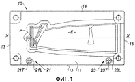
фиг.1 изображает матрицу на виде сверху со средством, образующим маркировки;figure 1 depicts the matrix in a plan view with means forming markings;
фиг.2 показывает деталь подушки, образующей маркировку;2 shows a detail of a pillow forming a marking;
фиг.3 показывает установку матрицы на ползуне пресса;figure 3 shows the installation of the matrix on the slider of the press;
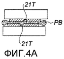
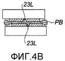
фиг.4А и 4В показывают штыри для проверки совмещения между подушками перед тем, как они расплющиваются.4A and 4B show pins for checking alignment between pillows before they flatten.
На фиг.1 показан матричный узел 10 для горячей объемной штамповки компрессора или лопатки вентилятора турбореактивного двигателя. Штамп имеет форму матрицы прямоугольного сечения, главная поверхность 11 которой здесь содержит оттиск Е половины лопатки. Эта главная поверхность 11 окаймлена четырьмя боковыми поверхностями 12, 13, 14, 15. Форма оттиска определяется соответствующими расчетными средствами и достигается механической обработкой, или электроимпульсной обработкой, или любыми другими средствами, известными специалисту в этой области.1 shows a
Например, она достигается на обрабатывающем станке с цифровым управлением или на электроискровой установке (ЭИУ). Вокруг оттиска обычно обеспечена периферийная зона ЕР для образования площадки, как известно в этой области. Пример реализации оттиска не является частью изобретения. Гравировка (вырезанный рельеф) содержит главную ось XX и по меньшей мере одну точку отсчета Р, образующую исходное положение для обработки оттиска. Таким образом, геометрическая форма оттиска определяется относительно обоих этих продольных и поперечных эталонов. Продольные боковые поверхности 12 и 14 параллельны оси XX. Поперечные поверхности 13 и 15 перпендикулярны ей.For example, it is achieved on a digitally controlled processing machine or on an electrospark installation (EIU). Around the print is usually provided a peripheral zone EP for the formation of the site, as is known in this area. An example implementation of the print is not part of the invention. Engraving (cut relief) contains the main axis XX and at least one reference point P, forming the initial position for processing the print. Thus, the geometric shape of the print is determined relative to both of these longitudinal and transverse standards. The
Законченный штамп для горячей объемной штамповки детали содержит вторую матрицу с оттиском половины лопатки такой формы, которая дополняет первую. Для горячей объемной штамповки детали обе матрицы располагаются и фиксируются в ползуне пресса, нижнем ползуне и верхнем ползуне. Заготовка штампуемой детали располагается в нижней матрице, и пресс приводится в действие. При сближении обе матрицы деформируют заготовку, и получается деталь такой формы, которую образуют оттиски, при ударном контакте по всему периметру.The finished stamp for hot stamping of a part contains a second matrix with an impression of half of the blade of a shape that complements the first. For hot volume stamping of a part, both matrices are located and fixed in the press slider, lower slider and upper slider. The blank of the stamped part is located in the lower die, and the press is driven. When approaching, both matrices deform the workpiece, and you get a part of such a shape that the prints form, with impact contact around the entire perimeter.
Качество штамповки частично зависит от правильного расположения обоих оттисков относительно друг друга в момент удара. Это расположение зависит как от правильного расположения оттисков в их соответствующей матрице, так и от правильного расположения обеих матриц относительно друг друга.The quality of stamping partially depends on the correct location of both prints relative to each other at the time of impact. This location depends on the correct location of the prints in their respective matrix, and on the correct location of both matrices relative to each other.
В устройстве согласно изобретению этого результата можно достигнуть легко и эффективно.In the device according to the invention, this result can be achieved easily and efficiently.
Согласно изобретению вместе с оттиском Е гравированием выполняются две подушки 21 и 23. Обе эти подушки выступают относительно верхней поверхности 11 матрицы. Обе подушки здесь имеют форму диска, но они могут принимать другую форму. Увеличенное изображение подушки 21 показано в перспективе на фиг.2. Каждая подушка содержит две перпендикулярные канавки 21L, 21Т и 23L, 23Т соответственно.According to the invention, two
Две продольные канавки 21L и 23L выполнены параллельно оси XX оттиска, на заданном расстоянии. Здесь обе канавки находятся на одинаковом расстоянии от оси XX. Поэтому они соосны. Поперечные канавки 21Т и 23Т перпендикулярны предыдущим, и каждая из них расположена на заданном расстоянии от точки отсчета Р. Положения оттиска и канавок, таким образом, легко определяются в пространстве относительно друг друга.Two
С этими средствами 21 и 23 проверка положения оттиска на матрице, с одной стороны, и визуальная проверка правильного совмещения матриц во время операций горячей объемной штамповки, с другой стороны, могут быть выполнены.With these
Что касается первой операции проверки, после обработки штампа положение подушек 21 и 23 относительно боковых поверхностей 12, 14 и 13, 15 измеряется испытанием, например, на трехмерной измерительной машине (ТИМ). Таким образом, выполняется проверка каждой из двух матриц на то,As for the first verification operation, after processing the stamp, the position of the
что поверхности 12 и 14 надлежащим образом параллельны направлению канавок 21L и 23L и находятся на правильном расстоянии от последних, с одной стороны, иthat the
что поверхности 13 и 15 надлежащим образом параллельны направлению канавок 21Т и 23Т и находятся на правильном расстоянии от последних, с другой стороны.that the
Если на одном из двух штампов замечают отклонение относительно теоретического размера, приступают к правке боковой поверхности (поверхностей) одного из штампов, чтобы сделать указанные расстояния идентичными на обеих матрицах.If a deviation with respect to the theoretical size is noticed on one of the two dies, proceed to editing the side surface (s) of one of the dies to make the indicated distances identical on both matrices.
Если отклонение замечают относительно теоретического размера на каждом штампе, приступают к правке на штампе с наименьшим дефектом.If the deviation is noticed regarding the theoretical size on each stamp, proceed to edit the stamp with the smallest defect.
Таким образом получают штампы, у которых оттиски совмещены безошибочно. Использование таких подушек обеспечивает быструю проверку с высокой точностью измерения.In this way, stamps are obtained in which the prints are correctly combined. The use of such pads provides quick verification with high measurement accuracy.
После изготовления матрицы устанавливаются на ползунах пресса. Установка выполняется закреплением боковых поверхностей матриц на упорных поверхностях В1 и В2. Вид сверху ползуна 100 пресса показан схематически. Например, расположение боковых поверхностей 12 и 14 регулируется с помощью так называемых "наклонных" клиньев 31 и 32. Эти клинья имеют дигедральную форму (образуются двумя пересекающимися плоскостями) и расположены таким образом, чтобы иметь две параллельные поверхности и две наклонные поверхности относительно последних, находящиеся в контакте друг с другом. При перемещении одного клина относительно другого, параллельно их параллельным поверхностям, последние раздвигаются или сближаются. Оба клина прижимаются, один к боковой поверхности 14 матрицы, другой к упору 110, который выполнен заодно с ползуном. Другая боковая поверхность 12 матрицы будет прижимать упор 120, который выполнен заодно с ползуном. Эта система с наклонным клином поэтому позволяет матрице перемещаться перпендикулярно поверхностям 12 и 14; таким образом возможна регулировка в положении на ползуне в поперечном направлении. При необходимости между клином 120 и боковой поверхностью 12 ставят металлические полоски.After manufacturing, the matrices are mounted on the sliders of the press. The installation is carried out by fixing the lateral surfaces of the matrices on the thrust surfaces B1 and B2. A top view of the
Для регулировки положения в продольном направлении можно использовать винт, который давит на поверхность 13 и толкает матрицу на упор 150, выполненный заодно с ползуном. Положение матрицы поэтому может быть отрегулировано в продольном направлении. Если нужно, между боковой поверхностью 15 и упором 150 можно установить металлическую полоску.To adjust the position in the longitudinal direction, you can use a screw that presses on the
Для проверки положения обоих штампов относительно друг друга выполняют следующее.To check the position of both dies relative to each other, the following is performed.
Штырь, выполненный из свинца или другого деформируемого в холодном состоянии материала, располагается на каждой из двух подушек нижнего штампа, и верхний штамп опускается, пока он не расплющит оба штыря.A pin made of lead or other cold-formed material is located on each of the two pillows of the lower die, and the upper die is lowered until it flattenes both pins.
Оба штыря показаны на фиг.4А и 4В после того, как они расплющились, в положении между подушками.Both pins are shown in FIGS. 4A and 4B after they have flattened, between the pillows.
Оператор может легко проверить, что канавки 21Т (или 23Т) верхней и нижней подушек не совмещены в иллюстрируемом примере. Перенеся назад деформированный таким образом штырь в измерительное устройство, он/она могут точно определить правку, которую следует выполнить в продольном положении.The operator can easily verify that the
Подобно этому, он/она может проверить, исследуя канавки 23L (или 21L), что обе матрицы расположены неправильно в поперечном направлении.Similarly, he / she can verify by examining the
Такие точные и маркирующие средства, простые в употреблении, становятся доступными, и при необходимости с их помощью могут быть выполнены корректировки правильного положения оттисков относительно друг друга.Such precise and easy-to-use marking tools are made available and, if necessary, adjustments can be made to the correct position of the prints relative to each other.
Используя эти средства, можно также проверить вращения штампов под воздействием напряжения при штамповке во время первого использования штампов, выполняя проверку со штырями одновременно с ударным воздействием.Using these tools, you can also check the rotation of the dies under the influence of stress during stamping during the first use of dies, performing a check with pins at the same time as impact.
Эта проверка выполняется после каждой обработки или повторной гравировки и с каждым разом, когда начинается горячая объемная штамповка.This check is performed after each machining or re-engraving and each time hot stamping begins.
Наконец, с помощью штырей можно проверить зазор между верхним и нижним штампами после ударного воздействия относительно необходимой толщины площадки.Finally, with the help of pins, it is possible to check the gap between the upper and lower dies after the impact with respect to the required thickness of the site.
Claims (6)
Applications Claiming Priority (2)
| Application Number | Priority Date | Filing Date | Title |
|---|---|---|---|
| FR0403230 | 2004-03-29 | ||
| FR0403230A FR2867992B1 (en) | 2004-03-29 | 2004-03-29 | FORGING MATRIX WITH MEANS OF REPERAGE |
Publications (2)
| Publication Number | Publication Date |
|---|---|
| RU2005108677A RU2005108677A (en) | 2006-10-10 |
| RU2378080C2 true RU2378080C2 (en) | 2010-01-10 |
Family
ID=34878459
Family Applications (1)
| Application Number | Title | Priority Date | Filing Date |
|---|---|---|---|
| RU2005108677/02A RU2378080C2 (en) | 2004-03-29 | 2005-03-28 | Die block for forging with marking facilities |
Country Status (7)
| Country | Link |
|---|---|
| US (1) | US7370506B2 (en) |
| EP (1) | EP1582278B1 (en) |
| CN (1) | CN100548530C (en) |
| DE (1) | DE602005000451T2 (en) |
| ES (1) | ES2281053T3 (en) |
| FR (1) | FR2867992B1 (en) |
| RU (1) | RU2378080C2 (en) |
Families Citing this family (13)
| Publication number | Priority date | Publication date | Assignee | Title |
|---|---|---|---|---|
| GB0915949D0 (en) * | 2009-09-11 | 2009-10-28 | Rolls Royce Plc | A die former |
| CN101811169B (en) * | 2010-04-09 | 2012-03-21 | 无锡透平叶片有限公司 | Subtype self-locking structure of blade mould and subtype design method |
| CN103009018B (en) * | 2011-09-20 | 2015-10-28 | 沈阳黎明航空发动机(集团)有限责任公司 | A kind of Ultra-fine Grained, high-strength alloy blade forging manufacture method |
| CN102974736A (en) * | 2012-11-30 | 2013-03-20 | 无锡透平叶片有限公司 | Positioning structure for turbine blade blank |
| CN102974735B (en) * | 2012-12-06 | 2015-03-25 | 无锡透平叶片有限公司 | Positioning adjustment structure of large-sized forging die |
| FR3014150B1 (en) * | 2013-11-29 | 2018-03-02 | Safran Aircraft Engines | BLOWER, ESPECIALLY FOR A TURBOMACHINE |
| CN103691866B (en) * | 2013-12-15 | 2015-10-14 | 无锡透平叶片有限公司 | A kind of method improving blade blank position stability on mould |
| CN103673950A (en) * | 2013-12-15 | 2014-03-26 | 无锡透平叶片有限公司 | Method for quickly detecting offset amount of blade forging die |
| CN104493040A (en) * | 2014-12-23 | 2015-04-08 | 无锡透平叶片有限公司 | Die base guide structure for blade forging |
| CN105414436B (en) * | 2015-12-31 | 2018-07-06 | 无锡透平叶片有限公司 | A kind of blade forging mold convenient for detection forging offsetting amount |
| CN110355315A (en) * | 2018-04-11 | 2019-10-22 | 辽宁五一八内燃机配件有限公司 | A kind of automatic forging positioning die device |
| FR3097791B1 (en) * | 2019-06-28 | 2021-06-18 | Safran Aircraft Engines | HOT CONFORMATION CORE OF A METAL PIECE AND MANUFACTURING, REGENERATION AND CONFORMATION PROCESS |
| RU2737836C1 (en) * | 2020-04-03 | 2020-12-03 | Федеральное государственное бюджетное образовательное учреждение высшего образования "Рыбинский государственный авиационный технический университет имени П.А. Соловьева" | Blade stamping die |
Family Cites Families (9)
| Publication number | Priority date | Publication date | Assignee | Title |
|---|---|---|---|---|
| DE1232439B (en) * | 1965-04-24 | 1967-01-12 | Fuchs Fa Otto | Testing device for pneumatic monitoring of a die press |
| US3762210A (en) * | 1970-10-05 | 1973-10-02 | Doncasters Monk Bridge Ltd | Forging dies for the forging of turbine and compressor blades or vanes |
| US4195510A (en) * | 1978-06-26 | 1980-04-01 | Juergens William A | Draw bead having alternating pressure surfaces and grooves |
| US4930334A (en) * | 1989-07-25 | 1990-06-05 | Deere & Company | Quick change structure for trim die |
| CN1048994A (en) * | 1989-10-18 | 1991-02-06 | 航空工业部红原锻铸厂 | Large-size steam turbine titanium alloy linear leaf forging and device |
| US5083371A (en) * | 1990-09-14 | 1992-01-28 | United Technologies Corporation | Hollow metal article fabrication |
| US5471923A (en) * | 1994-12-19 | 1995-12-05 | Chrysler Corporation | Multiple stamping dies with cumulative stamping markers and method of stampings parts |
| US6539767B2 (en) * | 2000-08-31 | 2003-04-01 | Sequa Can Machinery, Inc. | Method and apparatus for forming a container component |
| US7007535B2 (en) * | 2003-10-14 | 2006-03-07 | Stolle Machinery Company, Llc | Method and apparatus for aligning components of a press |
-
2004
- 2004-03-29 FR FR0403230A patent/FR2867992B1/en not_active Expired - Fee Related
-
2005
- 2005-03-28 RU RU2005108677/02A patent/RU2378080C2/en active
- 2005-03-29 CN CNB2005100697581A patent/CN100548530C/en active Active
- 2005-03-29 US US11/091,764 patent/US7370506B2/en active Active
- 2005-03-29 DE DE602005000451T patent/DE602005000451T2/en active Active
- 2005-03-29 EP EP05102453A patent/EP1582278B1/en active Active
- 2005-03-29 ES ES05102453T patent/ES2281053T3/en active Active
Also Published As
| Publication number | Publication date |
|---|---|
| US20050247101A1 (en) | 2005-11-10 |
| FR2867992A1 (en) | 2005-09-30 |
| FR2867992B1 (en) | 2007-06-29 |
| US7370506B2 (en) | 2008-05-13 |
| ES2281053T3 (en) | 2007-09-16 |
| EP1582278B1 (en) | 2007-01-17 |
| EP1582278A1 (en) | 2005-10-05 |
| DE602005000451T2 (en) | 2007-11-15 |
| DE602005000451D1 (en) | 2007-03-08 |
| RU2005108677A (en) | 2006-10-10 |
| CN1754635A (en) | 2006-04-05 |
| CN100548530C (en) | 2009-10-14 |
Similar Documents
| Publication | Publication Date | Title |
|---|---|---|
| RU2378080C2 (en) | Die block for forging with marking facilities | |
| RU2355503C2 (en) | Parts manufacturing method by precision forging | |
| US9539651B2 (en) | Method for machining center holes of forged rotary body and system for machining center holes of forged rotary body | |
| JPS5826685A (en) | Track chain link and its forging method | |
| CN108246845B (en) | Titanium alloy plate isothermal bending process optimization method | |
| CN108161122A (en) | A kind of cermet cold saw saw blade manufacturing process | |
| CN114367713B (en) | Machining method for segmented 3D printing turbine guide vane blank | |
| JP2006320996A (en) | Method of manufacturing second die | |
| JPH07328757A (en) | Die for trimming press and trimming press method | |
| CN207900375U (en) | A kind of cermet cold saw saw blade manufacturing device | |
| US6398886B1 (en) | Method and device for completing outer joint elements that are formed without cutting | |
| CN108723448A (en) | The processing tool and processing method of a kind of angle guide rail or inclined-plane | |
| JP3405077B2 (en) | Press apparatus, press-formed member, and forming method thereof | |
| KR100256538B1 (en) | Manufacturing method of mold | |
| CN112008156B (en) | Production process of copper-riveting saw blade matrix | |
| CN117380884A (en) | Mold design method for assisting in correcting offset of precise die forging | |
| US20230364667A1 (en) | Inlet lip skin manufacturing method | |
| JP2003245718A (en) | Method for bending material to be processed | |
| Zayas-Figueras et al. | Comparative Study about Dimensional Accuracy and Surface Finish of Constant-Breadth Cams Manufactured by FFF and CNC Milling. Micromachines 2023, 14, 377 | |
| JPS5834208B2 (en) | Manufacturing method for punches and dies in drawing molds | |
| Wisselink et al. | Tool deformation during the shape rolling of stator vanes | |
| JPH1133988A (en) | Method for adjusting clearance of die, and punching die | |
| RU2197351C2 (en) | Method of making punch for shaping double-curvature articles | |
| Lin et al. | An implementation of drive key cellular manufacturing | |
| Lin et al. | Planning a cost-effective cellular manufacturing process—a case study |
Legal Events
| Date | Code | Title | Description |
|---|---|---|---|
| RZ4A | Other changes in the information about an invention | ||
| PD4A | Correction of name of patent owner |