RU2376107C2 - Component for casting with usage of embedded parts, cylinder sleeve, block of cylinders and manufacturing method of cylinder sleeve - Google Patents
Component for casting with usage of embedded parts, cylinder sleeve, block of cylinders and manufacturing method of cylinder sleeve Download PDFInfo
- Publication number
- RU2376107C2 RU2376107C2 RU2008104701/02A RU2008104701A RU2376107C2 RU 2376107 C2 RU2376107 C2 RU 2376107C2 RU 2008104701/02 A RU2008104701/02 A RU 2008104701/02A RU 2008104701 A RU2008104701 A RU 2008104701A RU 2376107 C2 RU2376107 C2 RU 2376107C2
- Authority
- RU
- Russia
- Prior art keywords
- protrusions
- cylinder liner
- metal
- casting
- metal coating
- Prior art date
Links
Images


Classifications
-
- B—PERFORMING OPERATIONS; TRANSPORTING
- B22—CASTING; POWDER METALLURGY
- B22D—CASTING OF METALS; CASTING OF OTHER SUBSTANCES BY THE SAME PROCESSES OR DEVICES
- B22D19/00—Casting in, on, or around objects which form part of the product
-
- C—CHEMISTRY; METALLURGY
- C23—COATING METALLIC MATERIAL; COATING MATERIAL WITH METALLIC MATERIAL; CHEMICAL SURFACE TREATMENT; DIFFUSION TREATMENT OF METALLIC MATERIAL; COATING BY VACUUM EVAPORATION, BY SPUTTERING, BY ION IMPLANTATION OR BY CHEMICAL VAPOUR DEPOSITION, IN GENERAL; INHIBITING CORROSION OF METALLIC MATERIAL OR INCRUSTATION IN GENERAL
- C23C—COATING METALLIC MATERIAL; COATING MATERIAL WITH METALLIC MATERIAL; SURFACE TREATMENT OF METALLIC MATERIAL BY DIFFUSION INTO THE SURFACE, BY CHEMICAL CONVERSION OR SUBSTITUTION; COATING BY VACUUM EVAPORATION, BY SPUTTERING, BY ION IMPLANTATION OR BY CHEMICAL VAPOUR DEPOSITION, IN GENERAL
- C23C24/00—Coating starting from inorganic powder
- C23C24/02—Coating starting from inorganic powder by application of pressure only
- C23C24/04—Impact or kinetic deposition of particles
-
- B—PERFORMING OPERATIONS; TRANSPORTING
- B22—CASTING; POWDER METALLURGY
- B22D—CASTING OF METALS; CASTING OF OTHER SUBSTANCES BY THE SAME PROCESSES OR DEVICES
- B22D19/00—Casting in, on, or around objects which form part of the product
- B22D19/0009—Cylinders, pistons
-
- B—PERFORMING OPERATIONS; TRANSPORTING
- B22—CASTING; POWDER METALLURGY
- B22D—CASTING OF METALS; CASTING OF OTHER SUBSTANCES BY THE SAME PROCESSES OR DEVICES
- B22D19/00—Casting in, on, or around objects which form part of the product
- B22D19/0081—Casting in, on, or around objects which form part of the product pretreatment of the insert, e.g. for enhancing the bonding between insert and surrounding cast metal
-
- C—CHEMISTRY; METALLURGY
- C23—COATING METALLIC MATERIAL; COATING MATERIAL WITH METALLIC MATERIAL; CHEMICAL SURFACE TREATMENT; DIFFUSION TREATMENT OF METALLIC MATERIAL; COATING BY VACUUM EVAPORATION, BY SPUTTERING, BY ION IMPLANTATION OR BY CHEMICAL VAPOUR DEPOSITION, IN GENERAL; INHIBITING CORROSION OF METALLIC MATERIAL OR INCRUSTATION IN GENERAL
- C23C—COATING METALLIC MATERIAL; COATING MATERIAL WITH METALLIC MATERIAL; SURFACE TREATMENT OF METALLIC MATERIAL BY DIFFUSION INTO THE SURFACE, BY CHEMICAL CONVERSION OR SUBSTITUTION; COATING BY VACUUM EVAPORATION, BY SPUTTERING, BY ION IMPLANTATION OR BY CHEMICAL VAPOUR DEPOSITION, IN GENERAL
- C23C28/00—Coating for obtaining at least two superposed coatings either by methods not provided for in a single one of groups C23C2/00 - C23C26/00 or by combinations of methods provided for in subclasses C23C and C25C or C25D
- C23C28/02—Coating for obtaining at least two superposed coatings either by methods not provided for in a single one of groups C23C2/00 - C23C26/00 or by combinations of methods provided for in subclasses C23C and C25C or C25D only coatings only including layers of metallic material
- C23C28/021—Coating for obtaining at least two superposed coatings either by methods not provided for in a single one of groups C23C2/00 - C23C26/00 or by combinations of methods provided for in subclasses C23C and C25C or C25D only coatings only including layers of metallic material including at least one metal alloy layer
-
- F—MECHANICAL ENGINEERING; LIGHTING; HEATING; WEAPONS; BLASTING
- F02—COMBUSTION ENGINES; HOT-GAS OR COMBUSTION-PRODUCT ENGINE PLANTS
- F02F—CYLINDERS, PISTONS OR CASINGS, FOR COMBUSTION ENGINES; ARRANGEMENTS OF SEALINGS IN COMBUSTION ENGINES
- F02F1/00—Cylinders; Cylinder heads
-
- F—MECHANICAL ENGINEERING; LIGHTING; HEATING; WEAPONS; BLASTING
- F02—COMBUSTION ENGINES; HOT-GAS OR COMBUSTION-PRODUCT ENGINE PLANTS
- F02F—CYLINDERS, PISTONS OR CASINGS, FOR COMBUSTION ENGINES; ARRANGEMENTS OF SEALINGS IN COMBUSTION ENGINES
- F02F1/00—Cylinders; Cylinder heads
- F02F1/004—Cylinder liners
-
- Y—GENERAL TAGGING OF NEW TECHNOLOGICAL DEVELOPMENTS; GENERAL TAGGING OF CROSS-SECTIONAL TECHNOLOGIES SPANNING OVER SEVERAL SECTIONS OF THE IPC; TECHNICAL SUBJECTS COVERED BY FORMER USPC CROSS-REFERENCE ART COLLECTIONS [XRACs] AND DIGESTS
- Y10—TECHNICAL SUBJECTS COVERED BY FORMER USPC
- Y10T—TECHNICAL SUBJECTS COVERED BY FORMER US CLASSIFICATION
- Y10T29/00—Metal working
- Y10T29/49—Method of mechanical manufacture
- Y10T29/49229—Prime mover or fluid pump making
- Y10T29/4927—Cylinder, cylinder head or engine valve sleeve making
- Y10T29/49272—Cylinder, cylinder head or engine valve sleeve making with liner, coating, or sleeve
Landscapes
- Engineering & Computer Science (AREA)
- Chemical & Material Sciences (AREA)
- Mechanical Engineering (AREA)
- Chemical Kinetics & Catalysis (AREA)
- Materials Engineering (AREA)
- Metallurgy (AREA)
- Organic Chemistry (AREA)
- Combustion & Propulsion (AREA)
- General Engineering & Computer Science (AREA)
- Cylinder Crankcases Of Internal Combustion Engines (AREA)
- Pistons, Piston Rings, And Cylinders (AREA)
- Coating By Spraying Or Casting (AREA)
Abstract
Description
Область техникиTechnical field
Изобретение относится к закладному элементу для литья, который заключен внутри металла отливки при литье, и к блоку цилиндров, который содержит этот закладной элемент в виде гильзы цилиндра.The invention relates to a mortgage element for casting, which is enclosed inside the cast metal during casting, and to a cylinder block, which contains this mortgage element in the form of a cylinder liner.
Уровень техникиState of the art
Закладные элементы для литья включают в себя, например, гильзы цилиндра, объединенные с блоком цилиндров путем литья с закладными элементами для формирования отверстий цилиндра. Для обеспечения высокого уровня округлости отверстия цилиндра внешняя круговая поверхность этого компонента, который контактирует с используемым в отливке закладным элементом, обязательно должна обладать значительной силой сцепления с блоком цилиндров.Embedded elements for casting include, for example, cylinder liners integrated with the cylinder block by injection molding with embedded elements to form cylinder openings. To ensure a high level of roundness of the cylinder bore, the outer circular surface of this component, which is in contact with the embedded element used in the casting, must necessarily have a significant adhesion to the cylinder block.
Для обеспечения этой значительной силы сцепления важно обеспечить соответствующее состояние внешней круговой поверхности гильзы цилиндра. Соответственно, предложена методика, согласно которой распыляемый слой покрывает внешнюю круговую поверхность гильзы цилиндра и образует поверхностный слой (например, публикация выложенной полезной модели Японии №53-163405). Эта публикация раскрывает поверхностный слой на внешней круговой поверхности гильзы цилиндра, на которую напыляют гранулированный металл, причем гранулированный металл ложится на поверхность неравномерно и образует шероховатости. Во время литья расплавленный металл втекает в углубления упомянутых шероховатостей и обеспечивает якорный эффект закрепления, обеспечивая значительную силу сцепления.To ensure this significant traction, it is important to ensure the appropriate condition of the outer circumferential surface of the cylinder liner. Accordingly, a technique is proposed according to which a sprayed layer covers the outer circumferential surface of a cylinder liner and forms a surface layer (for example, Japanese Utility Model Laid-Open Publication No. 53-163405). This publication discloses a surface layer on the outer circumferential surface of a cylinder liner on which a granular metal is sprayed, and the granular metal is unevenly deposited on the surface and forms roughnesses. During casting, molten metal flows into the recesses of the above-mentioned roughnesses and provides an anchor fixing effect, providing a significant adhesion force.
Также предложена методика, согласно которой пленку материала с низкой температурой плавления металлургически связывают с внешней круговой поверхностью гильзы цилиндра при помощи дробеструйного упрочнения или плазменным напылением (например, публикация выложенного патента Японии №2003-53508), и при этом оксидная пленка на поверхности не образуется. Эта методика обеспечивает более прочное сцепление гильзы цилиндра с блоком цилиндров.A technique has also been proposed according to which a film of a material with a low melting point is metallurgically bonded to the outer circumferential surface of a cylinder liner by shot peening or plasma spraying (for example, Japanese Patent Laid-Open Publication No. 2003-53508), and no oxide film is formed on the surface. This technique provides a stronger grip on the cylinder liner and the cylinder block.
Согласно еще одной предложенной методике слой активации из алюминиевого сплава формируют в качестве поверхностного слоя в области верхней мертвой точки и в области нижней мертвой точки внешней окружности гильзы цилиндра, и при этом слой активации создает металлическую связь с картером (например, публикация выложенного патента Японии №2003-120414).According to another proposed technique, an aluminum alloy activation layer is formed as a surface layer in the region of top dead center and in the region of bottom dead center of the outer circumference of the cylinder liner, and the activation layer creates a metal bond with the crankcase (for example, Japanese Patent Laid-Open Publication No. 2003 -120414).
Ввиду современной тенденции снижения веса двигателей внутреннего сгорания внедряются конструкции двигателей с короткими расстояниями между отверстиями цилиндра. Также в настоящее время действует тенденция повышения мощности двигателей. Соответственно, для блока цилиндров, выполненного путем литья с закладными элементами в виде гильзы цилиндра, необходимо усилить сцепление между гильзой цилиндра и блоком цилиндров, тем самым улучшая характеристики охлаждения.In view of the current trend of reducing the weight of internal combustion engines, engine designs with short distances between cylinder bores are being introduced. Also currently there is a tendency to increase engine power. Accordingly, for a cylinder block made by casting with embedded elements in the form of a cylinder liner, it is necessary to strengthen the adhesion between the cylinder liner and the cylinder block, thereby improving cooling performance.
Но согласно публикации выложенной полезной модели Японии №53-163405 и публикации выложенного патента Японии №2003-120414 напыленный слой на внешней круговой поверхности гильзы цилиндра формируют за счет того, что расплавленные при высокой температуре частицы металла соударяются с гильзой цилиндра. За счет этого формируют пленку оксида на поверхности напыленного слоя, и оксиды присутствуют в напыленном слое. В результате этого теплопроводность металла после напыления уменьшается по сравнению с его теплопроводностью до напыления. Это техническое решение не повышает характеристики охлаждения до удовлетворительного уровня.But according to the publication of Japanese Utility Model Laid-open No. 53-163405 and Japanese Laid-Open Publication No. 2003-120414, a sprayed layer on the outer circular surface of the cylinder liner is formed due to the fact that the metal particles melted at high temperature collide with the cylinder liner. Due to this, an oxide film is formed on the surface of the sprayed layer, and oxides are present in the sprayed layer. As a result of this, the thermal conductivity of the metal after deposition is reduced compared to its thermal conductivity before deposition. This technical solution does not increase the cooling performance to a satisfactory level.
Согласно публикации выложенного патента Японии №2003-53508 пленку из материала с низкой температурой плавления формируют на внешней круговой поверхности гильзы цилиндра. При контакте пленки с расплавленным металлом во время литья происходит сплавление под действием высокой температуры, в результате чего создается хорошая металлическая связь. Но, согласно публикации выложенной полезной модели Японии №2003-163405 и публикации выложенного патента Японии №2003-120414, сама упомянутая пленка образуется в высокотемпературном состоянии из расплава, например напылением. Поэтому неизбежно на поверхности образуется пленка оксида, и образуются слои оксида в упомянутой пленке. Поэтому такое техническое решение не гарантирует удовлетворительный уровень характеристик охлаждения. Согласно публикации выложенного патента Японии №2003-53508 используется дробеструйное упрочнение. Но дробеструйное упрочнение является способом обработки поверхности и не может сформировать сплошную пленку.According to Japanese Patent Laid-Open Publication No. 2003-53508, a film of a material with a low melting point is formed on the outer circumferential surface of the cylinder liner. Upon contact of the film with molten metal during casting, fusion occurs under the influence of high temperature, resulting in a good metal bond. But, according to the publication of Japanese Utility Model Laid-Open No. 2003-163405 and the Japanese Laid-Open Patent Publication No. 2003-120414, said film itself is formed in a high temperature state from a melt, for example by spraying. Therefore, an oxide film is inevitably formed on the surface, and oxide layers are formed in said film. Therefore, such a technical solution does not guarantee a satisfactory level of cooling performance. According to Japanese Patent Laid-Open Publication No. 2003-53508, shot peening is used. But shot peening is a method of surface treatment and cannot form a continuous film.
Сущность изобретенияSUMMARY OF THE INVENTION
Соответственно, изобретение направлено на обеспечение - в закладном элементе для литья, таком как гильза цилиндра, внешней круговой поверхности, которая заключена внутри металла отливки и имеет высокую теплопроводность между заливаемым металлом и слоем металла, сформированным на внешней круговой поверхности закладного элемента по завершении литья.Accordingly, the invention is directed to providing, in a cast-in element for casting, such as a cylinder liner, an external circular surface that is enclosed within the casting metal and has a high thermal conductivity between the metal being cast and the metal layer formed on the external circular surface of the embedded element at the end of the casting.
Согласно первому аспекту изобретения предлагается закладной элемент для литья, внешняя круговая поверхность которого заключена внутри металла отливки при литье. Слой металлического покрытия формируют на внешней круговой поверхности холодным распылением.According to a first aspect of the invention, there is provided a embedded element for casting, the outer circumferential surface of which is enclosed inside the cast metal during casting. A metal coating layer is formed on the outer circular surface by cold spraying.
В соответствии со вторым аспектом изобретения предложена гильза цилиндра, связанная с блоком цилиндров для двигателя внутреннего сгорания. Гильза цилиндра содержит корпус гильзы цилиндра и слой металлического покрытия. Корпус гильзы цилиндра имеет наружную круговую поверхность, заключенную в металл отливки при литье блока цилиндров. Слой металлического покрытия сформирован на внешней круговой поверхности холодным распылением.According to a second aspect of the invention, there is provided a cylinder liner associated with a cylinder block for an internal combustion engine. The cylinder liner comprises a cylinder liner body and a metal coating layer. The cylinder liner body has an outer circumferential surface enclosed in cast metal during casting of the cylinder block. A metal coating layer is formed on the outer circumferential surface by cold spraying.
Согласно третьему аспекту изобретения предложен блок цилиндров двигателя внутреннего сгорания. Блок цилиндров формируют литьем металла. Гильза цилиндра заключена в металл при литье с закладными элементами, в результате чего гильза цилиндра связана с блоком цилиндров. Внешняя круговая поверхность гильзы цилиндра, связанная с блоком цилиндров, имеет слой металлического покрытия, сформированный холодным распылением.According to a third aspect of the invention, there is provided a cylinder block of an internal combustion engine. The cylinder block is formed by casting metal. The cylinder liner is enclosed in metal during casting with embedded elements, as a result of which the cylinder liner is connected to the cylinder block. The outer circumferential surface of the cylinder liner associated with the cylinder block has a metal coating layer formed by cold spraying.
Согласно четвертому аспекту изобретения обеспечен способ изготовления гильзы цилиндра, которая при литье с закладными элементами заключаются в материал, формирующий блок цилиндров двигателя внутреннего сгорания. Согласно этому способу обеспечивают цилиндрический корпус гильзы цилиндра, холодным распылением формируют слой металлического покрытия на внешней круговой поверхности корпуса гильзы цилиндра.According to a fourth aspect of the invention, there is provided a method for manufacturing a cylinder liner which, when cast with embedded elements, is enclosed in a material forming a cylinder block of an internal combustion engine. According to this method, a cylindrical cylinder liner body is provided, a cold coating layer is formed of a metal coating layer on the outer circumferential surface of the cylinder liner body.
Прочие аспекты и преимущества изобретения станут очевидными из приводимого ниже описания, в совокупности с прилагаемыми чертежами, которые в качестве примера поясняют принципы изобретения.Other aspects and advantages of the invention will become apparent from the description below, taken in conjunction with the accompanying drawings, which, by way of example, explain the principles of the invention.
Краткое описание чертежейBrief Description of the Drawings
Изобретение, наряду с его объектами и преимуществами, поясняется приводимым ниже описанием предпочтительных в настоящее время вариантов осуществления в совокупности с прилагаемыми чертежами, на которых:The invention, along with its objects and advantages, is illustrated by the following description of the currently preferred embodiments in conjunction with the accompanying drawings, in which:
Фиг.1А - схематическое изображение гильзы цилиндра согласно первому осуществлению;1A is a schematic illustration of a cylinder liner according to a first embodiment;
Фиг.1В - схематическое изображение гильзы цилиндра согласно первому осуществлению;FIG. 1B is a schematic illustration of a cylinder liner according to a first embodiment; FIG.
Фиг.2А - схематическое изображение блока цилиндра согласно первому осуществлению;2A is a schematic illustration of a cylinder block according to a first embodiment;
Фиг.2В - схематическое изображение блока цилиндра согласно первому осуществлению;2B is a schematic illustration of a cylinder block according to a first embodiment;
Фиг.3 - схематическое изображение блока цилиндра согласно первому осуществлению, во время литья;Figure 3 is a schematic illustration of a cylinder block according to a first embodiment, during casting;
Фиг.4 - схематическое изображение гильзы цилиндра согласно второму осуществлению;4 is a schematic illustration of a cylinder liner according to a second embodiment;
Фиг.5 - схематическое изображение порядка изготовления гильзы цилиндра согласно второму осуществлению;5 is a schematic illustration of a manufacturing order of a cylinder liner according to a second embodiment;
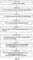
Фиг.6 - схема этапов изготовления гильзы цилиндра согласно второму осуществлению;6 is a diagram of the steps of manufacturing a cylinder liner according to a second embodiment;
Фиг.7 - схема этапов формирования выемки суженной формы в литейной форме согласно второму осуществлению;7 is a diagram of the steps of forming a recess of a narrowed mold in a mold according to a second embodiment;
Фиг.8 - схематическое изображение блока цилиндров согласно второму осуществлению, во время литья;Fig. 8 is a schematic illustration of a cylinder block according to a second embodiment, during casting;
Фиг.9 - схематическое изображение гильзы цилиндра согласно третьему осуществлению;Fig. 9 is a schematic illustration of a cylinder liner according to a third embodiment;
Фиг.10 - схематическое изображение блока цилиндров согласно третьему осуществлению во время литья;10 is a schematic illustration of a cylinder block according to a third embodiment during casting;
Фиг.11А - схема формы выступа, сформированного на внешней круговой поверхности гильзы согласно второму осуществлению или четвертому осуществлению;11A is a diagram of a shape of a protrusion formed on an outer circumferential surface of a sleeve according to a second embodiment or a fourth embodiment;
Фиг.11В - схема формы выступа, сформированного на внешней круговой поверхности гильзы согласно второму осуществлению или четвертому осуществлению;11B is a diagram of a shape of a protrusion formed on an outer circumferential surface of a sleeve according to a second embodiment or a fourth embodiment;
Фиг.12А - схема в контурных линиях формы выступа, сформированного на поверхности внешней круговой поверхности гильзы согласно второму осуществлению или четвертому осуществлению;12A is a diagram in contour lines of a protrusion shape formed on a surface of an outer circumferential surface of a sleeve according to a second embodiment or a fourth embodiment;
Фиг.12В - схема в контурных линиях формы выступа, сформированного на внешней круговой поверхности гильзы согласно второму осуществлению или четвертому осуществлению.12B is a diagram in contour lines of a protrusion shape formed on an outer circumferential surface of a sleeve according to a second embodiment or fourth embodiment.
Первое осуществлениеFirst exercise
Первое осуществление показано на фиг.1А, 1В, 2А и 2В. Фиг.1А показывает в перспективе гильзу 2 цилиндра согласно изобретению. Фиг.1В - частичное увеличенное поперечное сечение гильзы 2 цилиндра. Фиг.2А - частичное, в перспективе, изображение блока 4 цилиндра; гильза 2 цилиндра заключена в оболочку при литье с закладными элементами. Фиг.2В - частичное, увеличенное, поперечное сечение блока 4 цилиндров. Водяная рубашка 4а, сформированная вокруг гильзы 2 цилиндра, которая заключена внутри блока 4 цилиндров.The first implementation is shown in figa, 1B, 2A and 2B. 1A shows a perspective view of a
Конструкция гильзы 2 цилиндра
Корпус 2а гильзы 2 цилиндра согласно Фиг.1А и 1В представляет собой цилиндрический корпус, выполненный из чугуна. Гильза 2 сформирована формированием слоя 8 металлического покрытия на внешней круговой поверхности 6 корпуса 2а гильзы цилиндра (далее - внешняя круговая поверхность). Слой 8 металлического покрытия обеспечивает металлургическую связь гильзы 2 цилиндра с блоком 4 цилиндров во время литья.The
С учетом износостойкости, сопротивления к заклиниванию и формуемости предпочтительный состав чугуна является следующим:Given the wear resistance, resistance to jamming and formability, the preferred composition of cast iron is as follows:
Общий С: 2,9-3,7 вес.%,Total C: 2.9-3.7 wt.%,
Si: 1,6-2,8 вес.%,Si: 1.6-2.8 wt.%,
Mn: 0,5-1,0 вес.%,Mn: 0.5-1.0 wt.%,
Р: 0,05-0,4 вес.%,P: 0.05-0.4 wt.%,
При необходимости могут быть дополнительно введены следующие компоненты:If necessary, the following components can be additionally introduced:
Cr: 0,05-0,4 вес.%,Cr: 0.05-0.4 wt.%,
В: 0,03-0,08 вес.%,B: 0.03-0.08 wt.%,
Cu: 0,3-0,5 вес.%.Cu: 0.3-0.5 wt.%.
Состав слоя 8 металлического покрытияThe composition of the
В качестве металлического материала для формирования слоя 8 металлического покрытия используется металлический материал с высокой теплопроводностью. Например, алюминий, алюминиевый сплав, медь или медный сплав.As the metal material for forming the
Формирование слоя 8 металлического покрытияThe formation of
При формировании слоя 8 металлического покрытия на внешней круговой поверхности 6 этой поверхности заранее придают шероховатость при помощи устройства, придающего шероховатость (в частности, струйное или водоструйное устройство).When forming a
После придания шероховатости внешней круговой поверхности 6 обеспечивают соударение металлического материала с высокой теплопроводностью в твердом виде и в виде порошка с поверхностью 6 в сверхзвуковом потоке инертного газа при помощи устройства холодного распыления. Соответственно, частицы металлического материала с более высокой теплопроводностью подвергаются пластической деформации на внешней круговой поверхности 6 и формируют слой 8 металлического покрытия.After roughening the outer
Поскольку материалом отливки блока 4 цилиндров является алюминий или алюминиевый сплав, то такой же материал, что и материал блока, можно приготовить в виде порошка и использовать для холодного распыления.Since the casting material of the
Конструкция и литье блока 4 цилиндровDesign and casting of a
Согласно Фиг.2А и 2В блок 4 цилиндров сформирован с включением в себя гильзы 2 цилиндра при литье с закладными элементами. В частности, внешняя круговая поверхность 2 с гильзы 2 цилиндра, на которой сформирован слой 8 металлического покрытия, заключена внутри материала блока. Для материала блока использован легкий сплав в качестве материала отливки. В целях уменьшения веса и снижения себестоимости в качестве материала блока используется алюминий или алюминиевый сплав. Например, в качестве алюминиевого сплава можно использовать сплав согласно Японскому промышленному стандарту (JIS) ADC10 (соответствующий стандарт США: ASTM А380.0), или сплав согласно JIS ADC12 (соответствующий стандарт США: ASTM A383.0).2A and 2B, a
Гильзу 2 цилиндра согласно Фиг.1А помещают в литейную форму. Затем расплавленный алюминий или алюминиевый сплав заливают в литейную форму. Получают блок 4 цилиндров, в котором вся внешняя поверхность слоя 8 металлического покрытия заключена внутри алюминия или алюминиевого сплава.The
Согласно Фиг.3 во время отливки расплавленный металл 10 контактирует со слоем 8 металлического покрытия на внешней круговой поверхности 6 и нагревает его. Поскольку слой 8 металлического покрытия сформирован, как упомянуто выше, холодным распылением, поэтому на поверхности слоя 8 металлического покрытия присутствуют небольшое количество оксида, то есть на внешней круговой поверхности 2 с гильзы 2 цилиндра; и расплавленный металл 10 при его затвердевании создает достаточное сцепление со слоем 8 металлического покрытия. Тем самым отливка блока 4 цилиндра завершается.According to FIG. 3, during casting, the
Описываемое выше первое осуществление имеет следующие преимущества.The first embodiment described above has the following advantages.
(i) Слой 8 металлического покрытия формируют холодным распылением. Во время литья блока 4 цилиндров расплавленный металл 10 контактирует со слоем 8 металлического покрытия и затвердевает. При холодном распылении слой 8 металлического покрытия формируют на корпусе 2а гильзы цилиндра в нерасплавленном и в бескислородном состоянии, как упомянуто выше. При этом небольшое количество оксидных пленок или оксидных слоев формируются на поверхности таким образом сформированного слоя 8 металлического покрытия или внутри него.(i) The
Поэтому, когда гильза 2 цилиндра заключена внутри материала блока при литье с закладными элементами, блок 4 цилиндров формируется с прочным сцеплением между внешней круговой поверхностью 2с, которая является поверхностью слоя 8 металлического покрытия, и материалом блока. Поэтому повышается теплопроводность от границы слоя 8 металлического покрытия к блоку 4 цилиндров. Причем, поскольку в слое 8 металлического покрытия присутствуют небольшое количество оксидов, то сам слой 8 металлического покрытия имеет высокую теплопроводность.Therefore, when the
Вследствие этого теплопроводность от слоя 8 металлического покрытия к блоку 4 цилиндров достаточно высокая.As a result of this, the thermal conductivity from the
Соответственно, теплопроводность от гильзы 2 цилиндра к блоку 4 цилиндров в достаточной степени повышается, в результате чего водяная рубашка 4а в удовлетворительной степени охлаждает отверстие 2b цилиндра.Accordingly, the thermal conductivity from the
(ii) Как упомянуто выше, материал для слоя 8 металлического покрытия является металлическим материалом с высокой теплопроводностью. Слой 8 металлического покрытия содержит небольшое количество оксидов, как упомянуто выше, и обеспечивает материалу достаточную теплопроводность. Таким образом, преимущество (i) становится еще выгоднее.(ii) As mentioned above, the material for the
Второе осуществлениеSecond exercise
Фиг.4 показывает частичное поперечное сечение гильзы цилиндра согласно второму осуществлению. Корпус 12а гильзы 12 цилиндра выполнен из чугуна того же состава, что и в первом осуществлении, но выступы 17 имеют, каждый из которых имеет суженную форму, сформированы как одно целое с внешней круговой поверхностью 16. Каждый выступ 17 сформирован следующим образом.4 shows a partial cross section of a cylinder liner according to a second embodiment. The
(1) Каждый выступ 17 имеет самый узкий участок (сужение 17с) в средней части между ближним концом 17а и дальним концом 17b.(1) Each
(2) Каждый выступ 17 расширяется от сужения 17с к ближнему концу 17а и к дальнему концу 17b.(2) Each
(3) Каждый выступ 17 имеет по существу плоскую верхнюю поверхность 17d на дальнем конце 17b. Верхняя поверхность 17d является самой дальней поверхностью в радиальном направлении от корпуса 12а гильзы цилиндра.(3) Each
(4) По существу плоская поверхность (поверхность 17е основания) сформирована между выступами 17.(4) A substantially flat surface (
После придания шероховатости внешней круговой поверхности 16 на ней формируют слой 18 металлического покрытия. Слой 18 металлического покрытия металлургически связывается с материалом блока. Слой 18 металлического покрытия тот же, что и слой металлического покрытия в первом осуществлении. То есть металлический материал высокой теплопроводности используется в качестве металлического материала для формирования слоя 18 металлического покрытия. Например, могут использоваться: алюминий, алюминиевый сплав, медь или медный сплав.After roughening the outer
Способ изготовления гильзы 12 цилиндраA method of manufacturing a
Гильза 12 цилиндра изготавливается по этапам А-Н согласно Фиг.5. Каждый этап поясняется со ссылкой на Фиг.6.The
(Этап А)(Step A)
Взвесь С4 готовят смешиванием огнеупорного материала С1, связующего С2 и воды С3 в заданных соотношениях.Suspension C4 is prepared by mixing refractory material C1, a binder C2 and water C3 in predetermined proportions.
В этом осуществлении возможные пределы количеств огнеупорного материала С1, связующего С2 и воды С3; возможные пределы среднего размера частиц огнеупорного материала С1 установлены в следующих значениях:In this embodiment, the possible limits of the amounts of refractory material C1, binder C2 and water C3; possible limits of the average particle size of the refractory material C1 are set in the following values:
Количество огнеупорного материала С1: 8-30 вес.%.The amount of refractory material C1: 8-30 wt.%.
Количество связующего С2: 2-10 вес.%.The amount of binder C2: 2-10 wt.%.
Количество воды С3: 60-90 вес.%.The amount of water C3: 60-90 wt.%.
Средний размер частиц огнеупорного материала С1: 0,02-0,1 ммThe average particle size of the refractory material C1: 0.02-0.1 mm
(Этап В).(Step B).
Заданное количество поверхностно-активного вещества С5 вводят во взвесь С4 для получения раствора С6 для обработки литейной формы.A predetermined amount of surfactant C5 is introduced into a suspension of C4 to obtain a solution of C6 for processing the mold.
В этом осуществлении возможные пределы загрузки ПАВ С5 заданы следующими: 0,005 вес/%<X≤0,1 вес.% (Х - загрузка).In this embodiment, the possible loading limits of C5 surfactant are set as follows: 0.005 weight /% <X≤0.1 wt.% (X - loading).
(Этап С)(Step C)
Раствор С6 для обработки литейной формы наносят распылением на поверхность Pi внутренней окружности литейной формы Р, нагретой до заданной температуры и вращаемой. Причем раствор С6 для обработки литейной формы наносят таким образом, что слой раствора С6 для обработки литейной формы (слой С7 раствора для обработки литейной формы) единообразной толщины формируется при этом по всей поверхности Pi внутренней окружности.The solution C6 for processing the mold is applied by spraying onto the surface Pi of the inner circumference of the mold P, heated to a predetermined temperature and rotated. Moreover, the solution C6 for processing the mold is applied in such a way that a layer of solution C6 for processing the mold (layer C7 of the solution for processing the mold) of uniform thickness is formed along the entire surface Pi of the inner circle.
В этом осуществлении возможные пределы толщины слоя С7 из раствора для обработки литейной формы заданы следующими.In this embodiment, the possible limits of the thickness of the layer C7 from the solution for processing the mold are set as follows.
Толщина слоя С7: 0,5-1,5 мм.Layer thickness C7: 0.5-1.5 mm.
Фиг.7 показывает пример порядка этапов для формирования отверстия с сужением в слое С7 из раствора для обработки литейной формы.7 shows an example of the order of steps for forming a hole with a narrowing in the layer C7 from the solution for processing the mold.
Согласно Фиг.7 ПАВ С5 действует на пузырек D1 в слое С7, в результате чего углубление D2 формируется в направлении к внутренней окружности слоя С7. Углубление D2 доходит до поверхности Pi внутренней окружности литейной формы Р, в результате чего образуется отверстие D3 суженной формы в слое С7 из раствора для обработки литейной формы.According to Fig. 7, surfactant C5 acts on bubble D1 in layer C7, as a result of which a recess D2 is formed towards the inner circumference of layer C7. The recess D2 reaches the surface Pi of the inner circumference of the mold P, as a result of which a narrowed hole D3 is formed in the layer C7 from the mold for processing the mold.
(Этап D)(Step D)
После высыхания слоя С7 расплавленный чугун CI заливают во вращающуюся литейную форму Р. Соответственно, таким образом отливают корпус 12а гильзы цилиндра. При этом выступы, форма каждого из которых соответствует форме отверстия D3 слоя С7 раствора для обработки литейной формы, переносятся на корпус 12а гильзы цилиндра, в результате чего на поверхности 16 внешней круговой поверхности формируются выступы 17 (см. Фиг.4), каждый из которых имеет сужение.After the layer C7 has dried, the molten cast iron CI is poured into the rotating mold P. Accordingly, the
(Этап Е)(Step E)
После отверждения расплавленного металла CI и формирования корпуса 12а гильзы цилиндра этот корпус вынимают из литейной формы со слоем С7.After curing the molten metal CI and forming the
(Этап F)(Step F)
При помощи дутьевого устройства Ма раствор С7 удаляют с внешней круговой поверхности 16.Using the blowing device Ma, the C7 solution is removed from the outer
(Этап G)(Step G)
Устройством придания шероховатости (такое струйное устройство, как струйное устройство Ма или водоструйное устройство) внешней круговой поверхности 16 придают шероховатость.A roughening device (such as an inkjet device such as an inkjet device Ma or a water-jet device) roughen the outer
(Этап Н)(Step H)
При помощи устройства Mb холодного распыления внешнюю круговую поверхность 16 покрывают порошком имеющего высокую теплопроводность металла - как в первом осуществлении. При этом формируется слой 18 металлического покрытия на внешней круговой поверхности 16, который покрывает выступы 17.Using the cold spraying device Mb, the outer
Таким образом завершается выполнение гильзы 12 цилиндра, показываемой на чертеже Фиг.4.This completes the implementation of the
Соотношение поверхностей площадей выступа 17The ratio of the surface areas of the
В этом осуществлении возможные пределы первого соотношения S1 площадей и второго соотношения S2 площадей выступов 17 на корпусе 12а гильзы цилиндра, показанные ниже:In this embodiment, the possible limits of the first area ratio S1 and the second area ratio S2 of the
Первое соотношение S1 площадей: не более 10%.The first ratio of S1 areas: no more than 10%.
Второе соотношение S2 площадей: не более 55%.The second ratio of S2 areas: not more than 55%.
Либо эти соотношения можно задать в следующих значениях:.Or these ratios can be set in the following values :.
Первое соотношение S1 площадей: 10-50%.The first ratio of S1 areas: 10-50%.
Второе соотношение S2 площадей: 20-55%.The second ratio of S2 areas: 20-55%.
Первое соотношение S1 площадей соответствует площади поперечного сечения выступов 17 на единицу площади в плоскости, на высоте, равной 0,4 мм от поверхности 17е основания (расстояние в направлении высоты относительно поверхности 17е основания).The first area ratio S1 corresponds to the cross-sectional area of the
Второе соотношение S2 площадей соответствует площади поперечного сечения выступов 17 на единицу площади в плоскости на высоте, равной 0,2 мм от поверхности 17е основания (расстояние в направлении высоты относительно поверхности 17е основания).The second area ratio S2 corresponds to the cross-sectional area of the
Соотношения S1, S2 площадей определяют по контурным схемам (Фиг.11 и 12, поясняемым ниже) выступа 17, определяемым при помощи трехмерного лазерного измерительного устройства.The ratios S1, S2 of the areas are determined by the contour diagrams (11 and 12, explained below) of the
Высоту и плотность распределения выступов 17 определяют по глубине и плотности распределения отверстий D3 в слое С7 из раствора для обработки литейной формы, сформированных на этапе С. В частности, слой С7 сформирован таким образом, что высота выступов 17 составляет 0,5-1,5 мм, и плотность распределения выступов 17 или число выступов 17 на см2 внешней круговой поверхности: от пяти до шестидесяти.The height and distribution density of the
Изготовление блока цилиндровCylinder Block Making
Блок цилиндров изготавливают согласно следующим этапам: гильзу 12 цилиндра, показываемую на фиг.4, помещают в литейную форму, и расплавленный металл 20 материала блока наливают в литейную форму, в результате чего внешняя круговая поверхность 16 заключается внутри расплавленного металла 20. Материал блока тот же, который описывается в первом осуществлении 1, и используется тот же легкий сплав.The cylinder block is made according to the following steps: the
В блоке цилиндров согласно второму осуществлению, изготавливаемом аналогично, расплавленный металл 20 затвердевает, и при этом в достаточной степени осуществляет свое сцепление со слоем 18 металлического покрытия согласно механизму, излагаемому в первом осуществлении.In the cylinder block according to the second embodiment, manufactured in the same way, the
Второе осуществление имеет следующие преимущества:The second exercise has the following advantages:
(i) Помимо преимуществ первого осуществления - слой 18 металлического покрытия и корпус 12а гильзы цилиндра связываются друг с другом не только холодным распылением, но также и с помощью выступов 17, каждый из которых имеет суженную форму. Поэтому сила связи между корпусом 12а гильзы цилиндра и слоем 18 металлического покрытия и сила связи между корпусом 12а гильзы цилиндра и блоком цилиндров со слоем 18 металлического покрытия повышены в еще большей степени. Соответственно, обеспечен высокий уровень круглости расточки 12b цилиндра.(i) In addition to the advantages of the first embodiment, the
Помимо этого, выступы 17 суженной формы тоже повышают теплопроводность от корпуса 12а гильзы цилиндра к блоку цилиндров, в результате чего улучшаются характеристики охлаждения отверстия 12b цилиндра.In addition, tapered
Третье осуществлениеThird exercise
В третьем осуществлении используется тот же корпус 22а гильзы цилиндра, что и корпус гильзы цилиндра в первом осуществлении. Слой 28 металлического покрытия сформирован на корпусе 22а гильзы цилиндра из порошкового материала с низкой температурой плавления при помощи устройства холодного распыления, в результате чего получают гильзу 22 цилиндра.In the third embodiment, the same
Металлическим материалом с низкой температурой плавления может быть цинк, цинковый сплав, олово, оловянный сплав, свинец, свинцовый сплав, сурьма или сплав сурьмы.The low melting point metal material may be zinc, zinc alloy, tin, tin alloy, lead, lead alloy, antimony, or antimony alloy.
Аналогично слою металлического покрытия по первому осуществлению слой 28 металлического покрытия, сформированный холодным распылением, имеет несколько слоев оксида на поверхности и внутри.Similar to the metal coating layer of the first embodiment, the cold spray
Согласно Фиг.10 гильза 22 цилиндра заключена внутри расплавленного металла 30 материала блока, как в первом осуществлении, и тем самым выполнена отливка блока цилиндров. Во время литья, поскольку слой 28 металлического покрытия имеет температуру плавления более низкую, чем температура плавления материала блока (алюминий или алюминиевый сплав), формирующего расплавленный металл 30, поэтому расплавленный металл 30 плавится и сплавляется с поверхностью слоя 28 металлического покрытия, в результате чего формируется слой 28а сплавленного металла, как показано на фигурах. Отливка блока цилиндров завершается, когда расплавленный металл 30 и слой 28а расплавленного металла затвердевают. При этом слой 28а расплавленного металла приобретает прочную связь и сцепляется с блоком цилиндров и слоем 28 металлического покрытия.10, a
Третье осуществление имеет следующие преимущества.The third exercise has the following advantages.
(i) Поскольку для слоя 28 металлического покрытия используется металлический материал с низкой температурой плавления, то поверхность слоя 28 металлического покрытия, на котором сформированы пленки оксида, плавится при контакте с расплавленным металлом 30 и сплавляется с расплавленным металлом 30. За счет этого повышается теплопроводность между слоем 28 металлического покрытия и блоком цилиндров после изготовления слоя 28 металлического покрытия и таким образом преимущество (i) первого осуществления становится еще более действенным.(i) Since a metal material with a low melting point is used for the
(ii) Поскольку холодное распыление не расплавляет металл, то использование металлического материала с низкой температурой плавления не вызывает засорение устройства холодного распыления по причине чрезмерного расплавления. Поэтому технологичность формирования пленки не снижается. Помимо этого, в зависимости от типа металла, предотвращается сублимация. Таким образом, повышается эффективность формирования пленки.(ii) Since cold spraying does not melt the metal, the use of metallic material with a low melting point does not clog the cold spraying device due to excessive melting. Therefore, the processability of film formation is not reduced. In addition, depending on the type of metal, sublimation is prevented. Thus, the efficiency of film formation is increased.
Четвертое осуществлениеFourth exercise
Гильза цилиндра согласно четвертому осуществлению имеет тот же корпус 12а гильзы цилиндра, что и согласно второму осуществлению, с выступами 17, сформированными на внешней круговой поверхности 16. Слой металлического покрытия согласно четвертому осуществлению сформирован из металлического материала с низкой температурой плавления аналогично слою 28 металлического покрытия по третьему осуществлению.The cylinder liner according to the fourth embodiment has the same
Гильза цилиндра, сформированная как комбинация корпуса 12а гильзы цилиндра второго осуществления и слоя 28 металлического покрытия третьего осуществления, заключена внутри материала блока (алюминий или алюминиевый сплав) при литье с закладными элементами. Выполнение блока цилиндров таким образом завершается.The cylinder liner, formed as a combination of the
Описываемое выше четвертое осуществление имеет следующие преимущества:The fourth embodiment described above has the following advantages:
(i) Обеспечиваются преимущества второго и третьего осуществлений.(i) The benefits of the second and third implementations are provided.
Описание контурных линий выступаDescription of the contour lines of the protrusion
Далее поясняются контурные схемы выступов 17 второго осуществления, получаемые трехмерным лазерным измерительным устройством.Next, the contour diagrams of the
Контурная схема выступа 17Contour diagram of the
На фиг.11А и 11В поясняется измерение контурных линий выступа 17 по второму осуществлению, показанному на фиг.4. При составлении контурной схемы образец для измерения контурных линий помещают на испытательный стенд таким образом, чтобы основание 17е было обращено к бесконтактному трехмерному лазерному измерительному устройству. Измерение выполняют облучением поверхности 17е основания, и при этом лазерный луч направлен по существу перпендикулярно к поверхности 17е основания. Результаты измерения посылают в устройство обработки изображений для получения контурной схемы выступа 17 согласно фиг.11А.11A and 11B, the measurement of the contour lines of the
Фиг.11В показывает взаимосвязь между поверхностью 17е основания и контурными линиями (h0-h10). Согласно чертежу контурные линии h отображены на заданном интервале от поверхности 17е основания по высоте выступа 17 (направление согласно стрелке Y). Далее расстояние в направлении стрелки Y относительно поверхности 17е называется высотой измерения.11B shows the relationship between the
На фиг.11А и 11В показана схема, на которой контурные линии h показаны через интервал в 0,2 мм, но расстояние между контурными линиями h может изменяться сообразно необходимости.On figa and 11B shows a diagram in which the contour lines h are shown at an interval of 0.2 mm, but the distance between the contour lines h can vary according to need.
(а) Первое соотношение S1 площадей выступа 17(a) The first ratio S1 of the area of the
Фиг.12А показывает контурную схему, на которой контурные линии h менее чем на 0,4 мм по высоте не отображены (первая контурная схема). Площадь показываемой контурной схемы (W1 x W2) является единицей площади для измерения первого соотношения S1 площадей.12A shows a contour diagram in which contour lines h are not displayed less than 0.4 mm in height (first contour diagram). The area of the displayed contour diagram (W1 x W2) is a unit of area for measuring the first ratio S1 of areas.
В первой контурной схеме площадь области R4, окружаемой контурной линией h4 (зона заштрихованной части SR чертежа), соответствует площади поперечного сечения выступа, находящегося в плоскости на высоты измерения 0,4 мм (первая площадь поперечного сечения выступа 17). Число областей R4 первой контурной схемы (число областей N4) соответствует числу выступов 17 в первой контурной схеме.In the first contour diagram, the area of the region R4 surrounded by the contour line h4 (the area of the hatched portion SR of the drawing) corresponds to the cross-sectional area of the protrusion located in the plane at a measuring height of 0.4 mm (the first cross-sectional area of the protrusion 17). The number of regions R4 of the first contour diagram (the number of regions N4) corresponds to the number of
Первое соотношение S1 площадей вычисляется как соотношение общей площади областей R4 (SR4×N4) и площади контурной схемы (W1×W2). То есть первое соотношение S1 площадей соответствует общей площади первой площади поперечного сечения на единице площади в плоскости на измеряемой высоте, равной 0,4 мм. В контурной схеме выступов, то есть в контурной схеме внешней круговой поверхности корпуса гильзы цилиндра, первое соотношение S1 площадей равно соотношению общей площади первых площадей поперечного сечения и площади всей контурной схемы.The first area ratio S1 is calculated as the ratio of the total area of the regions R4 (SR4 × N4) and the area of the outline circuit (W1 × W2). That is, the first area ratio S1 corresponds to the total area of the first cross-sectional area per unit area in the plane at a measured height of 0.4 mm. In the contour diagram of the protrusions, that is, in the contour diagram of the outer circumferential surface of the cylinder liner body, the first area ratio S1 is equal to the ratio of the total area of the first cross-sectional areas and the area of the entire outline scheme.
Первое соотношение S1 площадей вычисляется следующим уравнением:The first area ratio S1 is calculated by the following equation:
S1=(SR4×N4)/(W1×W)×100 [%]S1 = (SR4 × N4) / (W1 × W) × 100 [%]
(b) Второе соотношение S2 площадей выступа 17(b) The second ratio S2 of the area of the
Фиг.12 В показывает контурную схему, на которой контурные линии h на высоте измерения менее 0,2 мм, не показаны (вторая контурная схема). Площадь контурной схемы (W1×W2) есть единица площади измерения второго соотношения S2 площадей.12B shows a contour diagram in which contour lines h at a measurement height of less than 0.2 mm are not shown (second contour diagram). The area of the contour diagram (W1 × W2) is the unit of area of measurement of the second ratio S2 of areas.
На второй контурной схеме площадь области R2, окружаемой контурной линией h2 (площадь заштрихованной части SR2 на чертеже), соответствует площади поперечного сечения выступа, который находится в плоскости на высоте измерения, равной 0,2 мм (вторая площадь поперечного сечения выступа 17). Число областей R2 на второй контурной схеме (число областей N2) соответствует числу выступов 17 второй контурной схемы. Поскольку площадь второй контурной схемы равна площади первой контурной схемы, поэтому число выступов 17 равно числу выступов N1.In the second contour diagram, the area of the region R2 surrounded by the contour line h2 (the area of the shaded part SR2 in the drawing) corresponds to the cross-sectional area of the protrusion, which is in the plane at a measurement height of 0.2 mm (the second cross-sectional area of the protrusion 17). The number of regions R2 in the second contour diagram (the number of regions N2) corresponds to the number of
Второе соотношение S2 площадей вычисляется как соотношение общей площади областей R2 (SR2×N2) и площади контурной схемы (W1×W2). То есть второе соотношение S2 площадей соответствует общей площади второго поперечного сечения на единице площади в плоскости на высоте измерения, равной 0,2 мм. В контурной схеме выступов, то есть в контурной схеме внешней круговой поверхности корпуса гильзы цилиндра, второе соотношение S2 площадей равно соотношению общей площади вторых площадей поперечного сечения и площади всей контурной схемы.The second area ratio S2 is calculated as the ratio of the total area of the regions R2 (SR2 × N2) and the area of the outline circuit (W1 × W2). That is, the second area ratio S2 corresponds to the total area of the second cross section per unit area in the plane at a measurement height of 0.2 mm. In the contour diagram of the protrusions, that is, in the contour diagram of the outer circumferential surface of the cylinder liner body, the second area ratio S2 is equal to the ratio of the total area of the second cross-sectional areas and the area of the entire outline scheme.
Второе соотношение S2 площадей вычисляется по следующему уравнению:The second area ratio S2 is calculated by the following equation:
S2=(SR2×N2)/(W1×W2)Ч100 [%]S2 = (SR2 × N2) / (W1 × W2) × 100 [%]
(c) Первая и вторая площади поперечного сечения выступа(c) The first and second cross-sectional areas of the protrusion
Первая площадь поперечного сечения выступа 17 вычисляется как площадь поперечного сечения одного выступа, находящегося в плоскости на высоте измерения, равной 0,4 мм, согласно контурным схемам. Вторая площадь поперечного сечения выступа 17 вычисляется как площадь поперечного сечения одного выступа, находящегося в плоскости на высоте измерения, равной 0,2 мм, согласно контурной схеме. Например, при помощи обработки изображения контурных схем первая площадь поперечного сечения выступов 17 определяется вычислением площади области R4 первой контурной схемы (Фиг.12А). Также обработкой изображения контурных схем вторую площадь поперечного сечения выступов 17 определяют вычислением площади области R2 второй контурной схемы (Фиг.12В).The first cross-sectional area of the
(d) Число выступов(d) The number of protrusions
Число выступов N1 вычисляют как число выступов 17 на единице площади (1 см2) на внешней круговой поверхности 16 гильзы цилиндра согласно контурным схемам. Например, при помощи обработки изображений контурных схем число выступов N1 определяют вычислением числа областей R4 в первой контурной схеме (Фиг.12А).The number of protrusions N1 is calculated as the number of
Гильза цилиндра, первое соотношение S1 площадей которой не превышало 10%, и гильза цилиндра, первое соотношение S1 площадей которой было меньше 10%, были выполнены на блоках цилиндров, и было сделано сравнение величины деформации этих отверстий цилиндра. Величина деформации последней оказалась более чем в три раза большей, чем у первой.The cylinder liner, the first ratio of S1 areas of which did not exceed 10%, and the cylinder liner, the first ratio of S1 areas of which was less than 10%, were made on the cylinder blocks, and a comparison was made of the strain value of these cylinder openings. The magnitude of the deformation of the latter was more than three times greater than that of the first.
Если второе соотношение S2 площадей более 55%, то пустотность значительно увеличивается. Термин «пустотность» означает соотношение между площадью пустот на границе гильзы цилиндра и блоком цилиндров с граничным поперечным сечением.If the second ratio of S2 areas is more than 55%, then the voidness increases significantly. The term "voidness" means the ratio between the void area at the boundary of the cylinder liner and the cylinder block with a boundary cross section.
Эти результаты подтверждают, что выполнение гильзы цилиндра, первое соотношение S1 площадей для которой не меньше 10% и второе соотношение S2 площадей для которой не более 55%, на блоке цилиндра повышает силу связи и прочность сцепления между материалом блока и гильзой цилиндра.These results confirm that the implementation of the cylinder liner, the first ratio of S1 areas for which is not less than 10% and the second ratio of S2 areas for which not more than 55%, on the cylinder block increases the bonding strength and adhesion between the material of the block and the cylinder liner.
Если верхний предел первого соотношения S1 площадей задан в значении 50%, то второе соотношение S2 площадей задается в значении не более 55%. Если нижний предел второго соотношения S2 площадей задан в значении 20%, то второе соотношение S1 площадей задается в значении не менее 10%.If the upper limit of the first area ratio S1 is set at 50%, then the second area ratio S2 is set at no more than 55%. If the lower limit of the second area ratio S2 is set to 20%, then the second area ratio S1 is set to at least 10%.
Прочие осуществленияOther implementations
(1) Во втором и четвертом осуществлениях внешней круговой поверхности придают шероховатость. Но поскольку выступы суженной формы дают достаточную силу связи со слоем металлического покрытия и блоком цилиндров, то придавать шероховатость внешней круговой поверхности не обязательно.(1) In the second and fourth embodiments, the outer circumferential surface is roughened. But since the protrusions of a narrowed form give sufficient bond strength with the metal coating layer and the cylinder block, it is not necessary to roughen the outer circular surface.
(2) Выступы согласно второму и четвертому осуществлений отвечают всем требованиям (а)-(d):(2) The protrusions according to the second and fourth implementations meet all the requirements of (a) - (d):
(а) высота выступов: 0,5-1,5 мм;(a) the height of the protrusions: 0.5-1.5 mm;
(b) на внешней круговой поверхности число выступов: от пяти до шестидесяти на 1 см2;(b) on the outer circular surface, the number of protrusions: from five to sixty per 1 cm 2 ;
(с) первое соотношение S1 площадей области внутри контурной линии на высоте в 0,4 мм не менее 10% в контурной схеме выступов; причем эта схема определена измерением внешней круговой поверхности по высоте выступов при помощи трехмерного измерительного устройства;(c) a first ratio S1 of the area of the region within the contour line at a height of 0.4 mm of at least 10% in the contour diagram of the protrusions; moreover, this scheme is determined by measuring the outer circular surface along the height of the protrusions using a three-dimensional measuring device;
(d) второе соотношение S2 площадей области внутри контурной линии на высоте в 0,2 мм не менее 55% в контурной схеме выступов; причем эта схема определена измерением внешней круговой поверхности по высоте выступов при помощи трехмерного измерительного устройства.(d) a second ratio S2 of the area areas within the contour line at a height of 0.2 mm of not less than 55% in the contour diagram of the protrusions; moreover, this scheme is determined by measuring the outer circular surface along the height of the protrusions using a three-dimensional measuring device.
Либо выступы второго и четвертого осуществлений могут отвечать всем следующим условиям (а)-(d'):Or the protrusions of the second and fourth implementations can meet all of the following conditions (a) - (d '):
(а) высота выступов: 0,5-1,5 мм;(a) the height of the protrusions: 0.5-1.5 mm;
(b) на внешней круговой поверхности число выступов: от пяти до шестидесяти на 1 см2;(b) on the outer circular surface, the number of protrusions: from five to sixty per 1 cm 2 ;
(с') первое соотношение S1 площадей области внутри контурной линии на высоте в 0,4 мм составляет 10-50% в контурной схеме выступов; причем эта схема определена измерением внешней круговой поверхности по высоте выступов при помощи трехмерного измерительного устройства;(c ') the first ratio S1 of the areas of the region inside the contour line at a height of 0.4 mm is 10-50% in the contour diagram of the protrusions; moreover, this scheme is determined by measuring the outer circular surface along the height of the protrusions using a three-dimensional measuring device;
(d') второе соотношение S2 площадей области внутри контурной линии на высоте в 0,2 мм составляет 20-55% в контурной схеме выступов; причем эта схема определена измерением внешней круговой поверхности по высоте выступов при помощи трехмерного измерительного устройства.(d ') the second ratio S2 of the area areas inside the contour line at a height of 0.2 mm is 20-55% in the contour diagram of the protrusions; moreover, this scheme is determined by measuring the outer circular surface along the height of the protrusions using a three-dimensional measuring device.
Также выступы согласно второму и четвертому осуществлениям могут соответствовать по меньшей мере одному из следующих условий (а)-(b):Also, the protrusions according to the second and fourth embodiments may correspond to at least one of the following conditions (a) to (b):
(а) высота выступов: 0,5-1,5 мм;(a) the height of the protrusions: 0.5-1.5 mm;
(b) на внешней круговой поверхности число выступов: от пяти до шестидесяти на 1 см2.(b) on the outer circular surface, the number of protrusions: from five to sixty per 1 cm 2 .
В этом варианте создается достаточная сила связи между гильзой цилиндра и блоком цилиндров; упрочняется связь между ними.In this embodiment, sufficient coupling force is created between the cylinder liner and the cylinder block; the connection between them is being strengthened.
Можно обеспечить выступы, соответствующие условиям (с) и (d), и по меньшей мере одному из условий (а) и (b) или условиям (c'), (d'), и по меньшей мере одному из условий (а) и (b).It is possible to provide protrusions corresponding to conditions (c) and (d), and at least one of conditions (a) and (b) or conditions (c '), (d'), and at least one of conditions (a) and (b).
В этом варианте создается достаточная сила связи между гильзой цилиндра и блоком цилиндров; упрочняется связь между ними.In this embodiment, sufficient coupling force is created between the cylinder liner and the cylinder block; the connection between them is being strengthened.
(3) Выступы 17 можно выполнить со следующими характеристиками: каждая из областей R4, окружаемая контурной линией h4 в контурной схеме согласно Фиг.11 и 12, является независимой от каждой другой (т.е. выступы 17 могут быть независимыми друг от друга в положении измерения на высоте 0,4 мм). Эта конфигурация также повышает силу связи между блоком цилиндров и гильзой цилиндра.(3) The
Если при измеренной высоте в 0,4 мм площадь каждого выступа 17 задается в значении 0,2-3,0 мм2, то во время изготовления устраняется возможность нарушения или ослабления силы связи выступов 17.If, at a measured height of 0.4 mm, the area of each
Claims (16)
Applications Claiming Priority (2)
| Application Number | Priority Date | Filing Date | Title |
|---|---|---|---|
| JP2005-201004 | 2005-07-08 | ||
| JP2005201004A JP4491385B2 (en) | 2005-07-08 | 2005-07-08 | Casting parts, cylinder block and cylinder liner manufacturing method |
Publications (2)
| Publication Number | Publication Date |
|---|---|
| RU2008104701A RU2008104701A (en) | 2009-08-20 |
| RU2376107C2 true RU2376107C2 (en) | 2009-12-20 |
Family
ID=37076026
Family Applications (1)
| Application Number | Title | Priority Date | Filing Date |
|---|---|---|---|
| RU2008104701/02A RU2376107C2 (en) | 2005-07-08 | 2006-07-06 | Component for casting with usage of embedded parts, cylinder sleeve, block of cylinders and manufacturing method of cylinder sleeve |
Country Status (9)
| Country | Link |
|---|---|
| US (1) | US7757652B2 (en) |
| EP (1) | EP1904666B1 (en) |
| JP (1) | JP4491385B2 (en) |
| KR (1) | KR101051899B1 (en) |
| CN (1) | CN100552088C (en) |
| BR (1) | BRPI0612788B1 (en) |
| DE (1) | DE602006004217D1 (en) |
| RU (1) | RU2376107C2 (en) |
| WO (1) | WO2007007814A1 (en) |
Cited By (1)
| Publication number | Priority date | Publication date | Assignee | Title |
|---|---|---|---|---|
| RU2767129C1 (en) * | 2020-06-24 | 2022-03-16 | Тпр Ко., Лтд. | Cylinder liner for casting with embedded elements |
Families Citing this family (36)
| Publication number | Priority date | Publication date | Assignee | Title |
|---|---|---|---|---|
| JP4429025B2 (en) * | 2004-01-09 | 2010-03-10 | トヨタ自動車株式会社 | Cylinder liner for casting |
| JP2006155694A (en) * | 2004-11-25 | 2006-06-15 | Sony Corp | Device and method for evaluating disk signal |
| JP2007016733A (en) * | 2005-07-08 | 2007-01-25 | Toyota Motor Corp | Cylinder liner and engine |
| JP4512001B2 (en) * | 2005-07-08 | 2010-07-28 | トヨタ自動車株式会社 | Cylinder liner, cylinder block, and cylinder liner manufacturing method |
| JP5388475B2 (en) * | 2008-04-30 | 2014-01-15 | Tpr株式会社 | Casting structure |
| JP5107837B2 (en) * | 2008-09-05 | 2012-12-26 | 富士重工業株式会社 | Cylinder liner, cylinder block, and cylinder liner manufacturing method |
| JP2011202576A (en) * | 2010-03-25 | 2011-10-13 | Teikoku Piston Ring Co Ltd | Cylinder liner |
| JP2012067740A (en) | 2010-08-25 | 2012-04-05 | Tpr Co Ltd | Cylinder liner for insert casting |
| FR2968358B1 (en) * | 2010-12-02 | 2015-08-28 | Peugeot Citroen Automobiles Sa | SHIELD FOR MOTOR BLOCK |
| DE102010055724A1 (en) * | 2010-12-22 | 2012-06-28 | Neue Halberg-Guss Gmbh | Cast element e.g. cylinder crankcase or cylinder head, has cooling device having cooling element which is embedded in cast element and has thermal conductivity higher than base material of cast element |
| EP2663790B1 (en) * | 2011-01-12 | 2016-10-05 | Ford Global Technologies, LLC | Method for roughening and coating a surface |
| US20130032120A1 (en) * | 2011-08-04 | 2013-02-07 | Caterpillar, Inc. | Piston For Internal Combustion Engine And Method |
| US8968855B2 (en) * | 2011-10-25 | 2015-03-03 | GM Global Technology Operations LLC | Method of forming a component having an insert |
| FR2990727B1 (en) * | 2012-05-21 | 2014-05-16 | Peugeot Citroen Automobiles Sa | CYLINDER SHIRT AND CYLINDER BLOCK |
| DE102012011992A1 (en) * | 2012-06-16 | 2013-12-19 | Volkswagen Aktiengesellschaft | Metallic cast component and method of making a metallic cast component |
| BR102012025551A2 (en) | 2012-10-05 | 2014-10-14 | Mahle Metal Leve Sa | CYLINDER SHIRT FOR ENGINING ON AN ENGINE BLOCK AND ENGINE BLOCK |
| US9335296B2 (en) | 2012-10-10 | 2016-05-10 | Westinghouse Electric Company Llc | Systems and methods for steam generator tube analysis for detection of tube degradation |
| BR102013005326A2 (en) | 2013-03-05 | 2014-12-02 | Mahle Metal Leve Sa | CYLINDER SHIRT FOR ENGINING ON AN ENGINE BLOCK AND ENGINE BLOCK |
| CN105473255B (en) | 2013-07-16 | 2019-05-07 | 费德罗-莫格尔公司 | Cylinder liner with adhesive layer |
| US10094325B2 (en) * | 2014-01-28 | 2018-10-09 | ZYNP International Corp. | Cylinder liner |
| WO2016085762A1 (en) * | 2014-11-24 | 2016-06-02 | Sikorsky Aircraft Corporation | Cast component and methods of manufacturing with cold spraying |
| US20160252042A1 (en) * | 2015-02-27 | 2016-09-01 | Avl Powertrain Engineering, Inc. | Cylinder Liner |
| KR101702222B1 (en) | 2015-06-22 | 2017-02-03 | 주식회사 금아하이드파워 | Manufacturing method of cylinder block |
| KR20170127903A (en) * | 2016-05-13 | 2017-11-22 | 현대자동차주식회사 | Cylinder Liner for Insert Casting and Method for Manufacturing thereof |
| CN106150740A (en) * | 2016-06-30 | 2016-11-23 | 中原内配集团安徽有限责任公司 | A kind of composite cylinder jacket and production method thereof |
| WO2018011362A1 (en) * | 2016-07-13 | 2018-01-18 | Oerlikon Metco Ag, Wohlen | Coating cylinder bores without prior activation of the surface |
| JP6572851B2 (en) * | 2016-08-29 | 2019-09-11 | トヨタ自動車株式会社 | Cylinder block of internal combustion engine and manufacturing method thereof |
| CN106438078A (en) * | 2016-08-30 | 2017-02-22 | 中原内配集团安徽有限责任公司 | Production method of aluminum-covered cylinder sleeve |
| CN108085674B (en) * | 2016-11-23 | 2020-01-03 | 中国科学院金属研究所 | Preparation method of aluminum alloy material for engine cylinder |
| US10253721B2 (en) * | 2017-04-12 | 2019-04-09 | GM Global Technology Operations LLC | Cylinder liner for internal combustion engine |
| KR102037582B1 (en) | 2017-12-18 | 2019-10-28 | 임락복 | A method of bonding a copper alloy on ferrous cast metal by insert casting. |
| US11935662B2 (en) | 2019-07-02 | 2024-03-19 | Westinghouse Electric Company Llc | Elongate SiC fuel elements |
| ES2955292T3 (en) | 2019-09-19 | 2023-11-29 | Westinghouse Electric Co Llc | Apparatus for performing in-situ adhesion testing of cold spray tanks and procedure for use |
| KR20210037051A (en) | 2019-09-26 | 2021-04-06 | 현대자동차주식회사 | Cylinder liner and cylinder block combined cylinder liner |
| CN111550323A (en) * | 2020-05-14 | 2020-08-18 | 扬州大学 | Cavitation-resistant cylinder sleeve with coating and preparation method thereof |
| CN113210586B (en) * | 2021-04-29 | 2022-12-06 | 共享装备股份有限公司 | Casting method of low-pressure inner cylinder of steam turbine |
Family Cites Families (24)
| Publication number | Priority date | Publication date | Assignee | Title |
|---|---|---|---|---|
| JPS53163405U (en) | 1977-05-30 | 1978-12-21 | ||
| JPS61169153A (en) * | 1985-01-23 | 1986-07-30 | Sumitomo Metal Ind Ltd | Composite metal-ceramic material and its production |
| JPH01287236A (en) * | 1988-05-13 | 1989-11-17 | Toyota Motor Corp | Method for internal chill of metallic member |
| JP2832032B2 (en) * | 1989-04-28 | 1998-12-02 | 日本ピストンリング株式会社 | Method for manufacturing hollow cylinder for cast-in |
| ES2143239T3 (en) * | 1995-10-31 | 2000-05-01 | Volkswagen Ag | PROCEDURE FOR THE CONSTRUCTION OF A SLIDING SURFACE ON A LIGHT METAL ALLOY. |
| DE19605946C1 (en) * | 1996-02-17 | 1997-07-24 | Ae Goetze Gmbh | Cylinder liner for internal combustion engines and their manufacturing process |
| DE19729017C2 (en) | 1997-07-08 | 2001-10-31 | Federal Mogul Burscheid Gmbh | Cylinder liner |
| DE19937934A1 (en) * | 1999-08-11 | 2001-02-15 | Bayerische Motoren Werke Ag | Cylinder crankcase, method for manufacturing the cylinder liners therefor and method for manufacturing the cylinder crankcase with these cylinder liners |
| DE10002440A1 (en) * | 2000-01-21 | 2001-08-02 | Daimler Chrysler Ag | Cylinder bushing sleeve used for casting in an engine block for an internal combustion engine has an adhesion promoting layer made of a nickel-aluminum alloy or a nickel-titanium alloy on the outer surface facing the engine block |
| IT1319899B1 (en) * | 2000-02-10 | 2003-11-12 | Fiat Ricerche | PROCEDURE FOR THE PRODUCTION OF A CYLINDER BLOCK FOR AN INTERNAL COMBUSTION ENGINE. |
| DE10019793C1 (en) | 2000-04-20 | 2001-08-30 | Federal Mogul Friedberg Gmbh | Cylinder liner for internal combustion engines and manufacturing processes |
| JP2003053508A (en) | 2001-08-14 | 2003-02-26 | Nissan Motor Co Ltd | Heat-conductive cylindrical member and its producing method, and aluminum alloy-made engine using heat- conductive cylindrical member |
| DE10147219B4 (en) | 2001-09-24 | 2004-02-26 | Daimlerchrysler Ag | Cylinder liner of an internal combustion engine |
| JP4210469B2 (en) * | 2002-05-13 | 2009-01-21 | 本田技研工業株式会社 | Method for producing cast iron cast member |
| DE60305691T2 (en) * | 2002-05-13 | 2007-05-31 | Honda Giken Kogyo K.K. | Cast-iron inner limb and method of preparation for it |
| JP4210468B2 (en) * | 2002-05-13 | 2009-01-21 | 本田技研工業株式会社 | Cast iron cast-in member |
| DE10347510B3 (en) * | 2003-10-13 | 2005-04-28 | Federal Mogul Burscheid Gmbh | Cylinder lining for internal combustion engine blocks comprises a first layer applied on an outer surface of the lining in one end of the lining and a second layer applied on an outer surface of the lining in another end of the lining |
| JP4429025B2 (en) * | 2004-01-09 | 2010-03-10 | トヨタ自動車株式会社 | Cylinder liner for casting |
| JP2007016733A (en) * | 2005-07-08 | 2007-01-25 | Toyota Motor Corp | Cylinder liner and engine |
| JP4474338B2 (en) * | 2005-07-08 | 2010-06-02 | トヨタ自動車株式会社 | Cylinder liner and engine |
| JP4512001B2 (en) * | 2005-07-08 | 2010-07-28 | トヨタ自動車株式会社 | Cylinder liner, cylinder block, and cylinder liner manufacturing method |
| JP4512002B2 (en) * | 2005-07-08 | 2010-07-28 | トヨタ自動車株式会社 | Cylinder liner |
| JP4584058B2 (en) * | 2005-07-08 | 2010-11-17 | トヨタ自動車株式会社 | Cylinder liner and manufacturing method thereof |
| JP4452661B2 (en) * | 2005-07-08 | 2010-04-21 | トヨタ自動車株式会社 | Cast-in part, cylinder block, cast-in part coating method and cylinder block manufacturing method |
-
2005
- 2005-07-08 JP JP2005201004A patent/JP4491385B2/en active Active
-
2006
- 2006-07-06 RU RU2008104701/02A patent/RU2376107C2/en active
- 2006-07-06 CN CNB2006800250072A patent/CN100552088C/en active Active
- 2006-07-06 BR BRPI0612788-6A patent/BRPI0612788B1/en active IP Right Grant
- 2006-07-06 US US11/481,084 patent/US7757652B2/en active Active
- 2006-07-06 KR KR1020087003180A patent/KR101051899B1/en active IP Right Grant
- 2006-07-06 EP EP06781033A patent/EP1904666B1/en active Active
- 2006-07-06 DE DE602006004217T patent/DE602006004217D1/en active Active
- 2006-07-06 WO PCT/JP2006/313913 patent/WO2007007814A1/en active Application Filing
Cited By (1)
| Publication number | Priority date | Publication date | Assignee | Title |
|---|---|---|---|---|
| RU2767129C1 (en) * | 2020-06-24 | 2022-03-16 | Тпр Ко., Лтд. | Cylinder liner for casting with embedded elements |
Also Published As
| Publication number | Publication date |
|---|---|
| BRPI0612788B1 (en) | 2018-03-27 |
| EP1904666B1 (en) | 2008-12-10 |
| KR101051899B1 (en) | 2011-07-28 |
| BRPI0612788A2 (en) | 2012-01-03 |
| JP4491385B2 (en) | 2010-06-30 |
| CN100552088C (en) | 2009-10-21 |
| EP1904666A1 (en) | 2008-04-02 |
| DE602006004217D1 (en) | 2009-01-22 |
| CN101218374A (en) | 2008-07-09 |
| WO2007007814A1 (en) | 2007-01-18 |
| US7757652B2 (en) | 2010-07-20 |
| US20070012180A1 (en) | 2007-01-18 |
| KR20080027928A (en) | 2008-03-28 |
| JP2007016738A (en) | 2007-01-25 |
| RU2008104701A (en) | 2009-08-20 |
Similar Documents
| Publication | Publication Date | Title |
|---|---|---|
| RU2376107C2 (en) | Component for casting with usage of embedded parts, cylinder sleeve, block of cylinders and manufacturing method of cylinder sleeve | |
| KR100939950B1 (en) | Insert casting component, cylinder block, method for forming coating on insert casting component, and method for manufacturing cylinder block | |
| US8037860B2 (en) | Cylinder liner and engine | |
| US7882818B2 (en) | Cylinder liner and engine | |
| EP2151568B1 (en) | Cylinder block containing a cylinder liner and method for manufacturing the same | |
| JP4512001B2 (en) | Cylinder liner, cylinder block, and cylinder liner manufacturing method | |
| RU2373021C2 (en) | Cylinder sleeve and manufacturing method thereof | |
| EP2422902B1 (en) | Cylinder liner for insert casting use | |
| RU2414526C2 (en) | Procedure for cylinder sleeve coating | |
| JPH09155523A (en) | Sleeve of die casting machine and production thereof | |
| JPS61202764A (en) | Production of sleeveless cylinder block | |
| JPS61202762A (en) | Production of sleeveless cylinder block |