JP4512001B2 - Cylinder liner, cylinder block, and cylinder liner manufacturing method - Google Patents
Cylinder liner, cylinder block, and cylinder liner manufacturing method Download PDFInfo
- Publication number
- JP4512001B2 JP4512001B2 JP2005201001A JP2005201001A JP4512001B2 JP 4512001 B2 JP4512001 B2 JP 4512001B2 JP 2005201001 A JP2005201001 A JP 2005201001A JP 2005201001 A JP2005201001 A JP 2005201001A JP 4512001 B2 JP4512001 B2 JP 4512001B2
- Authority
- JP
- Japan
- Prior art keywords
- cylinder liner
- outer peripheral
- peripheral surface
- cylinder
- adhesion
- Prior art date
- Legal status (The legal status is an assumption and is not a legal conclusion. Google has not performed a legal analysis and makes no representation as to the accuracy of the status listed.)
- Active
Links
- 238000004519 manufacturing process Methods 0.000 title claims description 34
- 230000002093 peripheral effect Effects 0.000 claims description 192
- 239000007921 spray Substances 0.000 claims description 60
- 238000000034 method Methods 0.000 claims description 57
- 239000003517 fume Substances 0.000 claims description 52
- 238000005266 casting Methods 0.000 claims description 45
- 238000007788 roughening Methods 0.000 claims description 42
- 239000000463 material Substances 0.000 claims description 34
- 238000005507 spraying Methods 0.000 claims description 32
- 238000011282 treatment Methods 0.000 claims description 30
- 238000000151 deposition Methods 0.000 claims description 27
- 229910052751 metal Inorganic materials 0.000 claims description 27
- 239000002184 metal Substances 0.000 claims description 27
- 238000007751 thermal spraying Methods 0.000 claims description 27
- 230000008021 deposition Effects 0.000 claims description 24
- 238000002485 combustion reaction Methods 0.000 claims description 19
- 239000000126 substance Substances 0.000 claims description 12
- 239000002245 particle Substances 0.000 claims description 11
- XLYOFNOQVPJJNP-UHFFFAOYSA-N water Substances O XLYOFNOQVPJJNP-UHFFFAOYSA-N 0.000 claims description 11
- 239000000956 alloy Substances 0.000 claims description 6
- 229910001234 light alloy Inorganic materials 0.000 claims description 6
- 238000005422 blasting Methods 0.000 claims description 5
- 239000002923 metal particle Substances 0.000 claims description 3
- 238000003754 machining Methods 0.000 claims 1
- 239000010410 layer Substances 0.000 description 161
- 238000005259 measurement Methods 0.000 description 21
- 230000036961 partial effect Effects 0.000 description 19
- 238000005304 joining Methods 0.000 description 17
- 239000011247 coating layer Substances 0.000 description 13
- 238000012545 processing Methods 0.000 description 12
- 229910052782 aluminium Inorganic materials 0.000 description 11
- XAGFODPZIPBFFR-UHFFFAOYSA-N aluminium Chemical compound [Al] XAGFODPZIPBFFR-UHFFFAOYSA-N 0.000 description 11
- 230000002829 reductive effect Effects 0.000 description 10
- 230000000694 effects Effects 0.000 description 9
- 239000011248 coating agent Substances 0.000 description 6
- 238000000576 coating method Methods 0.000 description 6
- 238000010586 diagram Methods 0.000 description 6
- 229910001018 Cast iron Inorganic materials 0.000 description 5
- 230000015572 biosynthetic process Effects 0.000 description 5
- 238000009826 distribution Methods 0.000 description 5
- 239000000446 fuel Substances 0.000 description 5
- 238000012546 transfer Methods 0.000 description 5
- 229910000838 Al alloy Inorganic materials 0.000 description 4
- 239000011230 binding agent Substances 0.000 description 4
- 230000000052 comparative effect Effects 0.000 description 4
- 238000001816 cooling Methods 0.000 description 4
- 230000006866 deterioration Effects 0.000 description 4
- 239000004094 surface-active agent Substances 0.000 description 4
- 239000011810 insulating material Substances 0.000 description 3
- 238000002156 mixing Methods 0.000 description 3
- 239000000203 mixture Substances 0.000 description 3
- 239000000725 suspension Substances 0.000 description 3
- XEEYBQQBJWHFJM-UHFFFAOYSA-N Iron Chemical compound [Fe] XEEYBQQBJWHFJM-UHFFFAOYSA-N 0.000 description 2
- UQSXHKLRYXJYBZ-UHFFFAOYSA-N Iron oxide Chemical compound [Fe]=O UQSXHKLRYXJYBZ-UHFFFAOYSA-N 0.000 description 2
- 238000013459 approach Methods 0.000 description 2
- 238000013329 compounding Methods 0.000 description 2
- 239000000498 cooling water Substances 0.000 description 2
- 238000007749 high velocity oxygen fuel spraying Methods 0.000 description 2
- 239000000843 powder Substances 0.000 description 2
- 239000007787 solid Substances 0.000 description 2
- 239000002344 surface layer Substances 0.000 description 2
- 238000012360 testing method Methods 0.000 description 2
- 0 C[C@](CCCC1)C11CCC(*C*)CC1 Chemical compound C[C@](CCCC1)C11CCC(*C*)CC1 0.000 description 1
- 230000002411 adverse Effects 0.000 description 1
- 238000009750 centrifugal casting Methods 0.000 description 1
- 229910010293 ceramic material Inorganic materials 0.000 description 1
- 230000008602 contraction Effects 0.000 description 1
- 238000002474 experimental method Methods 0.000 description 1
- 238000010438 heat treatment Methods 0.000 description 1
- 230000002401 inhibitory effect Effects 0.000 description 1
- 229910052742 iron Inorganic materials 0.000 description 1
- 230000001678 irradiating effect Effects 0.000 description 1
- 239000010705 motor oil Substances 0.000 description 1
- 239000003921 oil Substances 0.000 description 1
- 230000005855 radiation Effects 0.000 description 1
- 238000000926 separation method Methods 0.000 description 1
- 238000004381 surface treatment Methods 0.000 description 1
- 238000009864 tensile test Methods 0.000 description 1
- 239000011800 void material Substances 0.000 description 1
- 239000013585 weight reducing agent Substances 0.000 description 1
- 238000010284 wire arc spraying Methods 0.000 description 1
Images


Classifications
-
- F—MECHANICAL ENGINEERING; LIGHTING; HEATING; WEAPONS; BLASTING
- F02—COMBUSTION ENGINES; HOT-GAS OR COMBUSTION-PRODUCT ENGINE PLANTS
- F02F—CYLINDERS, PISTONS OR CASINGS, FOR COMBUSTION ENGINES; ARRANGEMENTS OF SEALINGS IN COMBUSTION ENGINES
- F02F1/00—Cylinders; Cylinder heads
-
- F—MECHANICAL ENGINEERING; LIGHTING; HEATING; WEAPONS; BLASTING
- F02—COMBUSTION ENGINES; HOT-GAS OR COMBUSTION-PRODUCT ENGINE PLANTS
- F02F—CYLINDERS, PISTONS OR CASINGS, FOR COMBUSTION ENGINES; ARRANGEMENTS OF SEALINGS IN COMBUSTION ENGINES
- F02F1/00—Cylinders; Cylinder heads
- F02F1/004—Cylinder liners
-
- B—PERFORMING OPERATIONS; TRANSPORTING
- B22—CASTING; POWDER METALLURGY
- B22D—CASTING OF METALS; CASTING OF OTHER SUBSTANCES BY THE SAME PROCESSES OR DEVICES
- B22D19/00—Casting in, on, or around objects which form part of the product
- B22D19/0009—Cylinders, pistons
-
- C—CHEMISTRY; METALLURGY
- C23—COATING METALLIC MATERIAL; COATING MATERIAL WITH METALLIC MATERIAL; CHEMICAL SURFACE TREATMENT; DIFFUSION TREATMENT OF METALLIC MATERIAL; COATING BY VACUUM EVAPORATION, BY SPUTTERING, BY ION IMPLANTATION OR BY CHEMICAL VAPOUR DEPOSITION, IN GENERAL; INHIBITING CORROSION OF METALLIC MATERIAL OR INCRUSTATION IN GENERAL
- C23C—COATING METALLIC MATERIAL; COATING MATERIAL WITH METALLIC MATERIAL; SURFACE TREATMENT OF METALLIC MATERIAL BY DIFFUSION INTO THE SURFACE, BY CHEMICAL CONVERSION OR SUBSTITUTION; COATING BY VACUUM EVAPORATION, BY SPUTTERING, BY ION IMPLANTATION OR BY CHEMICAL VAPOUR DEPOSITION, IN GENERAL
- C23C4/00—Coating by spraying the coating material in the molten state, e.g. by flame, plasma or electric discharge
- C23C4/02—Pretreatment of the material to be coated, e.g. for coating on selected surface areas
-
- F—MECHANICAL ENGINEERING; LIGHTING; HEATING; WEAPONS; BLASTING
- F02—COMBUSTION ENGINES; HOT-GAS OR COMBUSTION-PRODUCT ENGINE PLANTS
- F02F—CYLINDERS, PISTONS OR CASINGS, FOR COMBUSTION ENGINES; ARRANGEMENTS OF SEALINGS IN COMBUSTION ENGINES
- F02F1/00—Cylinders; Cylinder heads
- F02F1/02—Cylinders; Cylinder heads having cooling means
- F02F1/04—Cylinders; Cylinder heads having cooling means for air cooling
- F02F1/06—Shape or arrangement of cooling fins; Finned cylinders
- F02F1/08—Shape or arrangement of cooling fins; Finned cylinders running-liner and cooling-part of cylinder being different parts or of different material
-
- F—MECHANICAL ENGINEERING; LIGHTING; HEATING; WEAPONS; BLASTING
- F02—COMBUSTION ENGINES; HOT-GAS OR COMBUSTION-PRODUCT ENGINE PLANTS
- F02F—CYLINDERS, PISTONS OR CASINGS, FOR COMBUSTION ENGINES; ARRANGEMENTS OF SEALINGS IN COMBUSTION ENGINES
- F02F7/00—Casings, e.g. crankcases or frames
-
- F—MECHANICAL ENGINEERING; LIGHTING; HEATING; WEAPONS; BLASTING
- F05—INDEXING SCHEMES RELATING TO ENGINES OR PUMPS IN VARIOUS SUBCLASSES OF CLASSES F01-F04
- F05C—INDEXING SCHEME RELATING TO MATERIALS, MATERIAL PROPERTIES OR MATERIAL CHARACTERISTICS FOR MACHINES, ENGINES OR PUMPS OTHER THAN NON-POSITIVE-DISPLACEMENT MACHINES OR ENGINES
- F05C2251/00—Material properties
- F05C2251/04—Thermal properties
- F05C2251/048—Heat transfer
-
- Y—GENERAL TAGGING OF NEW TECHNOLOGICAL DEVELOPMENTS; GENERAL TAGGING OF CROSS-SECTIONAL TECHNOLOGIES SPANNING OVER SEVERAL SECTIONS OF THE IPC; TECHNICAL SUBJECTS COVERED BY FORMER USPC CROSS-REFERENCE ART COLLECTIONS [XRACs] AND DIGESTS
- Y10—TECHNICAL SUBJECTS COVERED BY FORMER USPC
- Y10T—TECHNICAL SUBJECTS COVERED BY FORMER US CLASSIFICATION
- Y10T29/00—Metal working
- Y10T29/49—Method of mechanical manufacture
- Y10T29/49229—Prime mover or fluid pump making
- Y10T29/4927—Cylinder, cylinder head or engine valve sleeve making
- Y10T29/49272—Cylinder, cylinder head or engine valve sleeve making with liner, coating, or sleeve
Landscapes
- Engineering & Computer Science (AREA)
- Chemical & Material Sciences (AREA)
- Mechanical Engineering (AREA)
- Combustion & Propulsion (AREA)
- General Engineering & Computer Science (AREA)
- Plasma & Fusion (AREA)
- Physics & Mathematics (AREA)
- Chemical Kinetics & Catalysis (AREA)
- Materials Engineering (AREA)
- Metallurgy (AREA)
- Organic Chemistry (AREA)
- Cylinder Crankcases Of Internal Combustion Engines (AREA)
- Pistons, Piston Rings, And Cylinders (AREA)
- Coating By Spraying Or Casting (AREA)
Description
本発明は、内燃機関のシリンダブロックの鋳造時に鋳造用金属に鋳ぐるまれることによりシリンダブロックに接合されてシリンダボアを形成するためのシリンダライナ、このシリンダライナにより形成されたシリンダブロック及びシリンダライナ製造方法に関する。 The present invention relates to a cylinder liner for forming a cylinder bore by being cast into a casting metal when casting a cylinder block of an internal combustion engine, and a cylinder block formed by the cylinder liner and a cylinder liner manufacture. Regarding the method.
シリンダブロック中にシリンダライナを配置するタイプの内燃機関において、機関運転時におけるシリンダボア壁の上部側と下部側との温度差を小さくして、排気損失や機械損失による燃費悪化やシリンダボアの真円度の低下などを防止する技術が提案されている(例えば特許文献1参照)。この特許文献1では、シリンダライナの外壁下部側に断熱材をコーティングすることにより、シリンダライナの外壁に接触している冷却水による冷却速度を調節してシリンダボア壁の上部側と下部側との温度差が小さくなるようにしている。
しかし特許文献1のシリンダライナでは外周面のほとんどが冷却水に接触している面であり、シリンダブロックと接触している部分が少ない。したがってシリンダはブロック側の支持が十分でなくシリンダボアの真円度が良好な状態に維持し難い。
However, in the cylinder liner of
シリンダブロックの支持を十分なものとしてシリンダボアの真円度を良好に維持するために、シリンダライナ外周面をシリンダブロックにて鋳ぐるむことでシリンダブロックとシリンダライナとを接合することが考えられる。 In order to sufficiently support the cylinder block and maintain the roundness of the cylinder bore well, it is conceivable to join the cylinder block and the cylinder liner by casting the outer peripheral surface of the cylinder liner with the cylinder block.
特許文献1に示されたシリンダライナをシリンダブロックにて鋳ぐるむことを考えた場合、特に、断熱材がコーティングされている下部側では、断熱材の表面がセラミック材からなるためシリンダブロックを構成する金属との接合が不十分になりやすい。このため特許文献1のシリンダライナでは、特に下部側にては十分にシリンダブロックによる支持が困難となり、シリンダボアの真円度に悪影響を与えるおそれがある。
Considering casting the cylinder liner shown in
このように特許文献1に示されたごとく、上下方向にて熱伝導状態に差を設けられるようにコントロールできるシリンダライナでは、シリンダボアの真円度の維持は十分ではなかった。
Thus, as shown in
本発明は、シリンダブロックに用いて、上下方向にて熱伝導状態に差を設けられると共に、シリンダライナ外周面がシリンダブロックに対して十分な接合力を有してシリンダボアの真円度を十分に高く維持できるシリンダライナの提供を目的とするものである。又、このようなシリンダライナを用いたシリンダブロックの提供、このようなシリンダライナの製造方法の提供を目的とするものである。 The present invention can be used for a cylinder block to provide a difference in the heat conduction state in the vertical direction, and the cylinder liner outer peripheral surface has a sufficient joining force with respect to the cylinder block to sufficiently round the cylinder bore. The purpose is to provide a cylinder liner that can be maintained at a high level. It is another object of the present invention to provide a cylinder block using such a cylinder liner and to provide a method for manufacturing such a cylinder liner.
以下、上記目的を達成するための手段及びその作用効果について記載する。
(1)請求項1に記載の発明は、括れた形状の突起が外周面上に複数形成されるものであって、内燃機関のシリンダブロックの鋳造に際して同外周面が直接又は中間層を介して鋳造用金属により鋳ぐるまれるシリンダライナにおいて、シリンダライナ上下方向にて外周面とシリンダブロック又は中間層との密着性に差が設けられ、且つシリンダライナ上部側での前記密着性がシリンダライナ下部側での前記密着性よりも高く設定されることをその要旨としている。
In the following, means for achieving the above object and its effects are described.
(1) The invention described in
このようにシリンダライナの外周面は、シリンダブロック又は中間層との間で、シリンダライナの上下方向にて密着性に差が設けられている。このことによりシリンダライナに対して直接あるいは中間層を介して、鋳ぐるむことにより形成されたシリンダブロックにおいて、上下方向にてシリンダボアの熱伝導状態に差を設けられる。
すなわち、上下方向において、シリンダライナ外周面とシリンダブロック又は中間層との密着性が高い位置ではシリンダライナ外周面とシリンダブロック又は中間層との境界部分において高熱伝導状態となり、逆に密着性が低い位置では前記境界部分において低熱伝導状態となる。
このようにシリンダライナ外周面における密着性を変更するのみで熱伝導状態に差を設けることができるので、例えば、シリンダライナの下部側の密着性を上部側よりも相対的に低くすることにより、シリンダボアの下部側の壁温を上げることができる。
そしてこのようにシリンダライナ外周面における密着性が部分的に低下したとしても、括れた形状の複数の突起が形成された外周面であるため、シリンダライナ外周面とシリンダブロック又は中間層との接合力は十分に大きい。したがって、本シリンダライナはシリンダブロックに対して十分な接合力を有することで真円度を十分に高く維持できる。
このように密着性に差を設けることで、シリンダライナの上部側におけるシリンダブロック側への熱伝導性を下部側よりも高くすることが容易に実現できる。このことによりシリンダボア内部の温度を上部側と下部側とで近づけて、共に適切な温度範囲に設定することができ、かつシリンダライナ外周面とシリンダブロック又は中間層との接合力は上部側も下部側も十分に大きいので真円度を十分に高く維持できる。
(2)請求項2に記載の発明は、請求項1に記載のシリンダライナにおいて、前記密着性の違いは、シリンダライナ上部側の外周面のみに粗面化処理が施されることにより維持されることを要旨としている。
このようにシリンダライナの上部側のみに粗面化処理を実施し、下部側には実施しないようにして、シリンダライナの上部側の密着性を下部側よりも高めることができる。
(3)請求項3に記載の発明は、請求項1に記載のシリンダライナにおいて、前記密着性の違いは、シリンダライナ上部側の外周面にシリンダライナ下部側の外周面よりも強い度合の粗面化処理が施されることにより維持されることを要旨としている。
シリンダライナは、成形された状態では表面に酸化物等の表層が存在し、シリンダブロックの鋳造時や中間層の形成時に、鋳造用金属や中間層に対する密着性が低いものとなる。この表層は粗面化処理により取り除くことができるが、シリンダライナの外周面上部側については下部側に比較して強い粗面化処理を実行しておくことにより、シリンダライナ外周面は上部側を下部側に比較して密着性を高くした構成に容易に設定することができる。
(4)請求項4に記載の発明は、請求項2または3に記載のシリンダライナにおいて、前記粗面化処理としてショットブラスト加工又はウォータージェット加工が施されることを要旨としている。
より具体的には粗面化処理は、ショットブラスト加工又はウォータージェット加工により容易に実現できる。
(5)請求項5に記載の発明は、括れた形状の突起が外周面上に複数形成されるものであって、内燃機関のシリンダブロックの鋳造に際して同外周面が直接又は中間層を介して鋳造用金属により鋳ぐるまれるシリンダライナにおいて、シリンダライナ上下方向にて外周面とシリンダブロック又は中間層との密着性に差が設けられ、且つシリンダライナ下部側での前記密着性がシリンダライナ上部側での前記密着性よりも低く設定されるものであって、この密着性の違いは、外周面とシリンダブロック又は中間層との密着を阻害する物質について、これがシリンダライナ上部側の外周面よりもシリンダライナ下部側の外周面に多く堆積していることにより維持されることをその要旨としている。
このようにシリンダライナの外周面の上部側よりも下部側に密着を阻害する物質が多く堆積した構成とすることによって、シリンダライナ外周面は下部側を上部側に比較して密着性を低くした構成に容易に設定することができる。したがってシリンダボア内部の温度を上部側と下部側とで適切な温度範囲に設定できると共に、前記突起の存在によりシリンダライナ外周面とシリンダブロック又は中間層との接合力は上部側も下部側も十分に大きいので真円度を十分に高く維持できる。
(6)請求項6に記載の発明は、括れた形状の突起が外周面上に複数形成されるものであって、内燃機関のシリンダブロックの鋳造に際して同外周面が直接又は中間層を介して鋳造用金属により鋳ぐるまれるシリンダライナにおいて、シリンダライナ上下方向にて外周面とシリンダブロック又は中間層との密着性に差が設けられ、且つシリンダライナ下部側での前記密着性がシリンダライナ上部側での前記密着性よりも低く設定されるものであって、この密着性の違いは、外周面とシリンダブロック又は中間層との密着を阻害する物質について、これがシリンダライナ下部側の外周面のみに堆積していることにより維持されることを要旨としている。
このようにして下部側のみ、密着を阻害する物質を堆積させていることにより容易に上部側と下部側との密着性に差を設けることができる。したがってシリンダボア内部の温度を上部側と下部側とで適切な温度範囲に設定できると共に、前記突起の存在によりシリンダライナ外周面とシリンダブロック又は中間層との接合力は上部側も下部側も十分に大きいので真円度を十分に高く維持できる。
(7)請求項7に記載の発明は、請求項5または6に記載のシリンダライナにおいて、前記密着を阻害する物質として溶射時に生じるヒュームが堆積していることを要旨としている。
このようにヒュームを密着を阻害する物質として利用できる。このことにより溶射処理時に上部側と下部側とで差を設けてシリンダライナ外周面に堆積させることで、容易に密着性に差を生じさせることができる。
(8)請求項8に記載の発明は、請求項7に記載のシリンダライナにおいて、前記密着を阻害する物質としてのヒューム上に前記中間層としての溶射層が形成されることを要旨としている。
このようにヒューム堆積層の上から溶射層を中間層として形成しても良い。このことにより、中間層によりヒューム堆積層が保護されて、シリンダライナの運搬移動時にヒューム堆積層が剥がれることがない。
そして中間層においてシリンダライナ外周面の上部側と下部側とで密着性の差が生じているので、この中間層に対して接合したシリンダブロックは、中間層を介してシリンダライナとの間で上下方向において熱伝導状態に差が生じることになる。しかも下部側において中間層とシリンダライナとの間で密着性が低下していても、前記突起により、シリンダライナと中間層との間の接合力、及びシリンダライナとシリンダブロックとの間の接合力は十分に大きい。
(9)請求項9に記載の発明は、請求項1〜8のいずれか一項に記載のシリンダライナにおいて、次の(a)及び(b)の少なくとも一方の条件が満たされる(a)「前記突起の高さが0.5mm〜1.5mmの範囲にある」(b)「前記突起の数が前記外周面上の1cm 2 当たり5個〜60個の範囲にある」ことを要旨としている。
このように括れた形状の複数の突起は、(a)及び(b)の条件の少なくとも一方を満たしているため、シリンダライナ外周面とシリンダブロック又は中間層との接合力の大きさを更に確実なものとできる。
Thus, the outer peripheral surface of the cylinder liner is provided with a difference in adhesion in the vertical direction of the cylinder liner between the cylinder block and the intermediate layer. As a result, in the cylinder block formed by casting the cylinder liner directly or through the intermediate layer, a difference is provided in the heat conduction state of the cylinder bore in the vertical direction.
That is, in the vertical direction, at a position where the adhesion between the cylinder liner outer circumferential surface and the cylinder block or the intermediate layer is high, a high heat conduction state is achieved at the boundary portion between the cylinder liner outer circumferential surface and the cylinder block or the intermediate layer, and conversely the adhesion is low. At the position, the boundary portion is in a low heat conduction state.
Thus, since it is possible to provide a difference in the heat conduction state only by changing the adhesion on the outer peripheral surface of the cylinder liner, for example, by making the adhesion on the lower side of the cylinder liner relatively lower than the upper side, The wall temperature on the lower side of the cylinder bore can be raised.
Even if the adhesion on the outer peripheral surface of the cylinder liner is partially reduced in this way, since the outer peripheral surface is formed with a plurality of constricted protrusions, the cylinder liner outer peripheral surface and the cylinder block or intermediate layer are joined. The power is big enough. Therefore, this cylinder liner can maintain the roundness sufficiently high by having a sufficient joining force to the cylinder block .
By providing a difference in adhesion as described above, it is possible to easily achieve higher thermal conductivity toward the cylinder block on the upper side of the cylinder liner than on the lower side. This allows the temperature inside the cylinder bore to be close to the upper side and the lower side, so that both can be set to an appropriate temperature range, and the bonding force between the cylinder liner outer peripheral surface and the cylinder block or intermediate layer is lower on the upper side and lower side. Since the side is sufficiently large, the roundness can be maintained sufficiently high.
(2) In the invention described in
As described above, the roughening process is performed only on the upper side of the cylinder liner and not on the lower side, so that the adhesion on the upper side of the cylinder liner can be improved as compared with the lower side.
(3) The invention described in
When the cylinder liner is molded, a surface layer such as an oxide is present on the surface, and when the cylinder block is cast or the intermediate layer is formed, the cylinder liner has low adhesion to the casting metal and the intermediate layer. This surface layer can be removed by roughening, but the outer surface of the cylinder liner is subjected to a stronger roughening process on the upper side of the outer surface of the cylinder liner than the lower side, so that the outer surface of the cylinder liner is It can be easily set to a configuration with higher adhesion compared to the lower side.
(4) The gist of the invention described in
More specifically, the roughening treatment can be easily realized by shot blast processing or water jet processing.
(5) The invention described in
As described above, the cylinder liner outer peripheral surface has a lower adhesion than the upper side of the cylinder liner outer peripheral surface by depositing a larger amount of substances that interfere with the lower side than the upper side of the outer peripheral surface of the cylinder liner. Can be easily set in the configuration. Therefore, the temperature inside the cylinder bore can be set to an appropriate temperature range between the upper side and the lower side, and the presence of the projections ensures that the bonding force between the cylinder liner outer peripheral surface and the cylinder block or intermediate layer is sufficient on both the upper side and the lower side. Since it is large, the roundness can be maintained sufficiently high.
(6) In the invention described in
Thus, by depositing the substance that inhibits the adhesion only on the lower side, a difference in the adhesion between the upper side and the lower side can be easily provided. Therefore, the temperature inside the cylinder bore can be set to an appropriate temperature range between the upper side and the lower side, and the presence of the projections ensures that the bonding force between the cylinder liner outer peripheral surface and the cylinder block or intermediate layer is sufficient on both the upper side and the lower side. Since it is large, the roundness can be maintained sufficiently high.
(7) The gist of the invention described in claim 7 is that in the cylinder liner according to
Thus, fume can be used as a substance that inhibits adhesion. As a result, a difference between the upper side and the lower side is provided at the time of thermal spraying and deposited on the outer peripheral surface of the cylinder liner, thereby making it possible to easily make a difference in adhesion.
(8) The gist of the invention described in
Thus, the thermal spray layer may be formed as an intermediate layer from above the fume deposition layer. As a result, the fume deposit layer is protected by the intermediate layer, and the fume deposit layer is not peeled off when the cylinder liner is transported and moved.
In the intermediate layer, there is a difference in adhesion between the upper side and the lower side of the outer peripheral surface of the cylinder liner. Therefore, the cylinder block joined to the intermediate layer moves vertically between the cylinder liner and the intermediate layer. There will be a difference in the heat conduction state in the direction. Moreover, even if the adhesion between the intermediate layer and the cylinder liner is lowered on the lower side, the bonding force between the cylinder liner and the intermediate layer and the bonding force between the cylinder liner and the cylinder block are caused by the protrusions. Is big enough.
(9) The invention according to claim 9 is the cylinder liner according to any one of
Since the plurality of projections having such a constricted shape satisfy at least one of the conditions (a) and (b), the magnitude of the bonding force between the cylinder liner outer peripheral surface and the cylinder block or the intermediate layer is further ensured. You can do it.
(10)請求項10に記載の発明は、請求項9に記載のシリンダライナにおいて、(c)「前記突起の高さ方向から前記外周面を測定して得られる前記突起の等高線図において、高さ0.4mmの等高線により囲まれる領域の面積率をS1としたとき、面積率S1が10%以上の範囲にある」及び(d)「前記突起の高さ方向から前記外周面を測定して得られる前記突起の等高線図において、高さ0.2mmの等高線により囲まれる領域の面積率をS2としたとき、面積率S2が55%以下の範囲にある」の条件がさらに満たされることをその要旨としている。
(10) The invention according to
更に(c)及び(d)の条件を加えた突起として形成されていることにより、種々の密着性に対応してシリンダブロックに対して十分な接合力を生じさせて真円度を十分に高く維持できる。Furthermore, by forming the projections to which the conditions (c) and (d) are added, a sufficient joining force is generated for the cylinder block corresponding to various adhesion properties, and the roundness is sufficiently high. Can be maintained.
(11)請求項11に記載の発明は、請求項9に記載のシリンダライナにおいて、(c)「前記突起の高さ方向から前記外周面を測定して得られる前記突起の等高線図において、高さ0.4mmの等高線により囲まれる領域の面積率をS1としたとき、面積率S1が10%〜50%の範囲にある」及び(d)「前記突起の高さ方向から前記外周面を測定して得られる前記突起の等高線図において、高さ0.2mmの等高線により囲まれる領域の面積率をS2としたとき、面積率S2が20%〜55%の範囲にある」の条件がさらに満たされることをその要旨としている。 (11) The invention described in claim 11 is the cylinder liner according to claim 9 , wherein (c) "in the contour map of the protrusion obtained by measuring the outer peripheral surface from the height direction of the protrusion, When the area ratio of the region surrounded by the contour line having a thickness of 0.4 mm is S1, the area ratio S1 is in the range of 10% to 50%. ”And (d)“ Measure the outer peripheral surface from the height direction of the protrusion. In the contour map of the projection obtained as described above, when the area ratio of the region surrounded by the contour line having a height of 0.2 mm is S2, the condition that the area ratio S2 is in the range of 20% to 55% is further satisfied. The gist of this is.
更にこのような(c)及び(d)の条件を加えた突起として形成されていても良く、このことにより、種々の密着性に対応してシリンダブロックに対して十分な接合力を生じさせて真円度を十分に高く維持できる。Further, it may be formed as a projection with the conditions (c) and (d) added, and this causes a sufficient bonding force to the cylinder block corresponding to various adhesion properties. Roundness can be maintained sufficiently high.
(12)請求項12に記載の発明は、請求項10または11に記載のシリンダライナにおいて、(e)「前記等高線図において、高さ0.4mmの等高線により囲まれる領域がそれぞれ独立している」及び(f)「前記等高線図において、高さ0.4mmの等高線により囲まれる領域の面積が0.2mm 2 〜3.0mm 2 の範囲にある」の条件をさらに満たすことをその要旨としている。
更に(e)、(f)の条件を加えた突起として形成されていることにより、シリンダブロックに対して、一層大きい接合力を生じて真円度を十分に高く維持できる。
(13)請求項13に記載の発明は、請求項1〜12のいずれか一項に記載のシリンダライナにおいて、シリンダライナ上部側及び下部側の外周面に前記中間層としての溶射層が形成されることをその要旨としている。
(12) The invention described in claim 12 is the cylinder liner according to claim 10 or 11, wherein (e) "in the contour map, regions surrounded by a contour line having a height of 0.4 mm are independent from each other. in "and (f)" the contour map, and its gist, further satisfying the condition of the area of a region surrounded by a contour line of height 0.4mm in the range of 0.2mm 2 ~3.0mm 2 " .
Further, since the protrusions are formed with the conditions (e) and (f) added, a larger joining force is generated on the cylinder block, and the roundness can be maintained sufficiently high.
(13) The invention according to claim 13 is the cylinder liner according to any one of
溶射により中間層を形成したシリンダライナとして構成することができる。この中間層は、シリンダライナ外周面との密着性において上下方向にて差を設けてあるので、この中間層に対して接合したシリンダブロックは、中間層を介してシリンダライナとの間で上下方向において熱伝導状態に差が生じることになる。しかも中間層とシリンダライナとの間で密着性が低下した部分が生じても、前記突起により、シリンダライナと中間層との間の接合力、及びシリンダライナとシリンダブロックとの間の接合力は十分に大きい。したがって前記請求項1に説明したごとくの作用効果を生じる。It can be configured as a cylinder liner having an intermediate layer formed by thermal spraying. Since this intermediate layer has a difference in the vertical direction in adhesion to the outer peripheral surface of the cylinder liner, the cylinder block joined to this intermediate layer is vertically connected to the cylinder liner via the intermediate layer. In this case, a difference occurs in the heat conduction state. In addition, even if there is a portion where the adhesion is lowered between the intermediate layer and the cylinder liner, the protrusions cause the bonding force between the cylinder liner and the intermediate layer and the bonding force between the cylinder liner and the cylinder block. Big enough. Therefore, the effect as described in the first aspect is produced.
(14)請求項14に記載の発明は、鋳造用金属としての軽合金材料によりシリンダライナを鋳ぐるむことにより、このシリンダライナと接合された態様で形成されるシリンダブロックにおいて、前記シリンダライナとして請求項1〜13のいずれか一項に記載のシリンダライナが設けられ、このシリンダライナの外周面又は中間層と前記軽合金材料とが接合されてなることを要旨としている。
(14) The invention according to claim 14 is a cylinder block formed by casting a cylinder liner with a light alloy material as a casting metal, and joined to the cylinder liner. one cylinder liner according to one of
このように前述した各請求項のいずれかのシリンダライナを、軽合金材料にて鋳ぐるむことにより形成されたシリンダブロックは、上下方向にてシリンダボアの熱伝導状態に差を設けられる。しかも前記突起の存在によりシリンダブロックとシリンダライナとの間の接合力は十分であるのでシリンダボアの真円度を十分に高く維持できるシリンダブロックを実現することができる。Thus, the cylinder block formed by casting the cylinder liner according to any one of the above-mentioned claims with a light alloy material is provided with a difference in the heat conduction state of the cylinder bore in the vertical direction. In addition, since the joining force between the cylinder block and the cylinder liner is sufficient due to the presence of the protrusion, it is possible to realize a cylinder block capable of maintaining the roundness of the cylinder bore sufficiently high.
(15)請求項15に記載の発明は、括れた形状の突起が外周面上に複数形成されるものであって、内燃機関のシリンダブロックの鋳造に際して同外周面が鋳造用金属により鋳ぐるまれるシリンダライナの製造方法において、前記括れた形状の複数の突起が外周面から突出して形成された状態のシリンダライナについて、その上部側の外周面に対してのみ粗面化処理を行う粗面化処理工程と、この粗面化処理工程をした後に上部側及び下部側の外周面に金属溶射材を溶射して溶射層を形成する上下溶射工程とを含むことをその要旨としている。
(15) In the invention described in
このように粗面化処理工程と上下溶射工程とを実行することにより、溶射層として形成された中間層は、シリンダライナの外周面に対して上部側では密着性が高く下部側では密着性が低くなるように設定できる。したがって上部側の熱伝導状態は下部側よりも高くなり、シリンダボア内部の温度を、上部側と下部側とで近づけて、共に適切な温度範囲に設定できるようになる。そしてシリンダライナ外周面の下部側で密着性が低下しても、括れた形状の複数の突起が外周面から突出して形成されているため、シリンダライナと溶射層との接合力及びシリンダライナとシリンダブロックとの接合力は十分に大きいので、真円度を十分に高く維持できる。 By performing the roughening treatment process and the vertical spraying process in this way, the intermediate layer formed as the sprayed layer has high adhesion on the upper side and high adhesion on the lower side with respect to the outer peripheral surface of the cylinder liner. Can be set to lower. Therefore, the heat conduction state on the upper side becomes higher than that on the lower side, and the temperature inside the cylinder bore can be brought closer between the upper side and the lower side, and both can be set to an appropriate temperature range. Even if the adhesion is reduced on the lower side of the outer peripheral surface of the cylinder liner, a plurality of constricted projections are formed to protrude from the outer peripheral surface, so that the bonding force between the cylinder liner and the sprayed layer and the cylinder liner and cylinder Since the joining force with the block is sufficiently large, the roundness can be maintained sufficiently high.
(16)請求項16に記載の発明は、括れた形状の突起が外周面上に複数形成されるものであって、内燃機関のシリンダブロックの鋳造に際して同外周面が鋳造用金属により鋳ぐるまれるシリンダライナの製造方法において、前記括れた形状の複数の突起が外周面から突出して形成された状態のシリンダライナについて、その上部側及び下部側の外周面に粗面化処理を行うとともに、上部側の外周面については下部側の外周面よりも粗面化処理の度合を強くする粗面化処理工程と、この粗面化処理工程をした後に上部側及び下部側の外周面に金属溶射材を溶射して溶射層を形成する上下溶射工程とを含むことをその要旨としている。 (16) In the invention described in claim 16 , a plurality of constricted protrusions are formed on the outer peripheral surface, and the outer peripheral surface is casted by a casting metal when casting the cylinder block of the internal combustion engine. In the cylinder liner manufacturing method, for the cylinder liner in a state in which the plurality of constricted projections are formed to protrude from the outer peripheral surface, the upper and lower outer peripheral surfaces are roughened, and the upper portion For the outer peripheral surface on the side, a roughening treatment step for increasing the degree of the roughening treatment on the outer peripheral surface on the lower side, and a metal spraying material on the outer peripheral surface on the upper side and the lower side after this roughening treatment step And a top and bottom thermal spraying step of forming a thermal spray layer by spraying.
このように粗面化処理工程についてはシリンダライナの上部側と下部側とで実行するが、下部側よりも上部側で強くなされるように差を設けても良い。このことによっても密着性の差が生じてシリンダボア内部の温度を上部側も下部側も適切な温度範囲に設定でき、更に、シリンダライナ外周面は括れた形状の複数の突起の存在により、溶射層及びシリンダブロックへの接合力も十分に大きいので、真円度を十分に高く維持できる。 As described above, the roughening process is performed on the upper side and the lower side of the cylinder liner, but a difference may be provided so as to be stronger on the upper side than on the lower side. This also causes a difference in adhesion, so that the temperature inside the cylinder bore can be set to an appropriate temperature range on both the upper side and the lower side, and the outer peripheral surface of the cylinder liner has a plurality of constricted projections, so that the thermal spray layer In addition, since the joining force to the cylinder block is sufficiently large, the roundness can be maintained sufficiently high.
(17)請求項17に記載の発明は、括れた形状の突起が外周面上に複数形成されるものであって、内燃機関のシリンダブロックの鋳造に際して同外周面が鋳造用金属により鋳ぐるまれるシリンダライナの製造方法において、前記括れた形状の複数の突起が外周面から突出して形成された状態のシリンダライナについて、その上部側の外周面に対して金属溶射材の溶融溶射粒子を衝突させ、これと同時に下部側の外周面には前記溶融溶射粒子の周辺部に生じるヒュームを衝突させ、これにより上部側の外周面に溶射層を形成するとともに下部側の外周面にヒューム堆積層を形成する分別溶射工程と、この分別溶射工程をした後に上部側及び下部側の外周面に金属溶射材の溶融溶射粒子を衝突させて同外周面に溶射層を形成する上下溶射工程とを含むことをその要旨としている。 (17) The invention according to claim 17 is such that a plurality of constricted protrusions are formed on the outer peripheral surface, and the outer peripheral surface is cast by a casting metal when casting the cylinder block of the internal combustion engine. In the cylinder liner manufacturing method, in the cylinder liner in a state where the plurality of constricted projections are formed to protrude from the outer peripheral surface, the molten thermal spray particles of the metal spray material are caused to collide with the outer peripheral surface on the upper side. At the same time, fumes generated in the peripheral portion of the molten spray particles collide with the outer peripheral surface of the lower side, thereby forming a sprayed layer on the outer peripheral surface of the upper side and forming a fume deposit layer on the outer peripheral surface of the lower side. And a vertical spraying step of forming a thermal spray layer on the outer peripheral surface by colliding the molten thermal spray particles of the metal thermal spray material with the outer peripheral surface of the upper side and the lower side after the fractional spraying step. And as its gist in that it comprises.
このように分別溶射工程と上下溶射工程とを実行することにより、ヒューム堆積層の上から溶射層を中間層として形成できる。このことにより上下方向においてシリンダライナと溶射層との密着性の差が生じてシリンダボア内部の温度を上部側も下部側も適切な温度範囲に設定でき、シリンダライナ外周面は括れた形状の複数の突起の存在により、溶射層及びシリンダブロックへの接合力も十分に大きいので、真円度を十分に高く維持できる。
しかも、溶射層によりヒューム堆積層が保護されているので、溶射層形成後のシリンダライナを運搬するために移動してもヒューム堆積層が剥がれることがない。
By performing the separate spraying process and the top and bottom spraying process in this way, the sprayed layer can be formed as an intermediate layer from above the fume deposition layer. This causes a difference in adhesion between the cylinder liner and the sprayed layer in the vertical direction, and the temperature inside the cylinder bore can be set to an appropriate temperature range on both the upper side and the lower side, and the cylinder liner outer peripheral surface has a plurality of constricted shapes. Due to the presence of the protrusion, the bonding force to the sprayed layer and the cylinder block is sufficiently large, so that the roundness can be maintained sufficiently high.
In addition, since the fume deposit layer is protected by the sprayed layer, the fume deposit layer does not peel off even when the cylinder liner is moved to transport the cylinder liner after the sprayed layer is formed.
(18)請求項18に記載の発明は、請求項17に記載のシリンダライナの製造方法において、前記分別溶射工程では、吸引装置によりシリンダライナの上部側から下部側に向けて気流を生じさせ、この状態のもとで前記溶射層及び前記ヒューム堆積層を形成することをその要旨としている。 (18) The invention according to claim 18 is the cylinder liner manufacturing method according to claim 17 , wherein, in the fractional spraying step, an air flow is generated from the upper side to the lower side of the cylinder liner by a suction device, The gist is to form the thermal spray layer and the fume deposition layer under this state.
分別溶射工程において、上述のごとく吸引装置を起動させることにより、シリンダライナの外周面の下部側に、より均一にかつ確実にヒュームを衝突させることができる。したがって下部側に、より確実にヒューム層を堆積させることができ、熱伝導状態の差も、より高精度に調節できる。 In the fractional spraying process, by starting the suction device as described above, it is possible to make the fumes collide with the lower side of the outer peripheral surface of the cylinder liner more uniformly and reliably. Therefore, the fume layer can be more reliably deposited on the lower side, and the difference in the heat conduction state can be adjusted with higher accuracy.
(19)請求項19に記載の発明は、請求項15〜18のいずれか一項に記載のシリンダライナの製造方法において、前記括れた形状の複数の突起が外周面から突出して形成された状態のシリンダライナとして、(a)「前記突起の高さが0.5mm〜1.5mmの範囲にある」及び(b)「前記突起の数が前記外周面上の1cm2当たり5個〜60個の範囲にある」の少なくとも一方の条件を満たすものを用いることをその要旨としている。
(19) The invention according to claim 19 is the cylinder liner manufacturing method according to any one of
このような突起が外周面に形成されたシリンダライナを用いることにより、シリンダライナと溶射層との間に密着性の低い場所が存在していても、より確実にシリンダライナと溶射層との接合力、及びシリンダライナとシリンダブロックとの接合力を大きくでき、シリンダボアの真円度を十分に高く維持できる。 By using a cylinder liner in which such protrusions are formed on the outer peripheral surface, even if there is a place with low adhesion between the cylinder liner and the thermal spray layer, the cylinder liner and the thermal spray layer can be more reliably joined. The force and the joining force between the cylinder liner and the cylinder block can be increased, and the roundness of the cylinder bore can be maintained sufficiently high.
(20)請求項20に記載の発明は、請求項19に記載のシリンダライナの製造方法において、前記括れた形状の複数の突起が外周面から突出して形成された状態のシリンダライナとして、(c)「前記突起の高さ方向から前記外周面を測定して得られる前記突起の等高線図において、高さ0.4mmの等高線により囲まれる領域の面積率をS1としたとき、面積率S1が10%以上の範囲にある」及び(d)「前記突起の高さ方向から前記外周面を測定して得られる前記突起の等高線図において、高さ0.2mmの等高線により囲まれる領域の面積率をS2としたとき、面積率S2が55%以下の範囲にある」の条件をさらに満たすものを用いることをその要旨としている。 (20) According to a twentieth aspect of the present invention, in the cylinder liner manufacturing method according to the nineteenth aspect, as the cylinder liner in a state where the plurality of constricted protrusions are formed to protrude from the outer peripheral surface, (c "In the contour map of the projection obtained by measuring the outer peripheral surface from the height direction of the projection, when the area ratio of the region surrounded by the contour line having a height of 0.4 mm is S1, the area ratio S1 is 10 %) ”And (d)“ in the contour map of the protrusion obtained by measuring the outer peripheral surface from the height direction of the protrusion, the area ratio of the region surrounded by the contour line having a height of 0.2 mm The gist is to use a material that further satisfies the condition that the area ratio S2 is in the range of 55% or less when S2.
更に(c)、(d)の条件を加えた突起が外周面に形成されたシリンダライナを用いることにより、シリンダライナの各種の密着性においても、溶射層及びシリンダブロックに対して十分な接合力を有して真円度を十分に高く維持できる。 Furthermore, by using a cylinder liner in which protrusions with the conditions (c) and (d) added are formed on the outer peripheral surface, a sufficient bonding force with respect to the sprayed layer and the cylinder block even in various adhesion properties of the cylinder liner. The roundness can be maintained sufficiently high.
(21)請求項21に記載の発明は、請求項19に記載のシリンダライナの製造方法において、前記括れた形状の複数の突起が外周面から突出して形成された状態のシリンダライナとして、(c)「前記突起の高さ方向から前記外周面を測定して得られる前記突起の等高線図において、高さ0.4mmの等高線により囲まれる領域の面積率をS1としたとき、面積率S1が10%〜50%の範囲にある」及び(d)「前記突起の高さ方向から前記外周面を測定して得られる前記突起の等高線図において、高さ0.2mmの等高線により囲まれる領域の面積率をS2としたとき、面積率S2が20%〜55%にある」の条件をさらに満たすものを用いることをその要旨としている。 (21) According to a twenty-first aspect of the present invention, in the cylinder liner manufacturing method according to the nineteenth aspect, as the cylinder liner in a state where the plurality of constricted protrusions are formed to protrude from the outer peripheral surface, (c "In the contour map of the projection obtained by measuring the outer peripheral surface from the height direction of the projection, when the area ratio of the region surrounded by the contour line having a height of 0.4 mm is S1, the area ratio S1 is 10 % And 50% ”and (d)“ area of a region surrounded by a contour line having a height of 0.2 mm in the contour map of the protrusion obtained by measuring the outer peripheral surface from the height direction of the protrusion. The gist is to use a material that further satisfies the condition that the area ratio S2 is 20% to 55% when the ratio is S2.
このような(c)、(d)の条件を加えた突起が外周面に形成されたシリンダライナを用いても良い。このことにより、シリンダライナの各種の密着性においても、溶射層及びシリンダブロックに対して十分な接合力を有して真円度を十分に高く維持できる。 You may use the cylinder liner in which the protrusion which added the conditions of such (c) and (d) was formed in the outer peripheral surface. Thereby, also in various adhesiveness of a cylinder liner, it has sufficient joining force with respect to a sprayed layer and a cylinder block, and can maintain roundness sufficiently high.
(22)請求項22に記載の発明は、請求項20または21に記載のシリンダライナの製造方法において、前記括れた形状の複数の突起が外周面から突出して形成された状態のシリンダライナとして、(e)「前記等高線図において、高さ0.4mmの等高線により囲まれる領域がそれぞれ独立している」及び(f)「前記等高線図において、高さ0.4mmの等高線により囲まれる領域の面積が0.2mm2〜3.0mm2の範囲にある」の条件をさらに満たすものを用いることをその要旨としている。 (22) The invention according to claim 22 is the cylinder liner manufacturing method according to claim 20 or 21 , wherein the plurality of constricted protrusions are formed so as to protrude from the outer peripheral surface. (E) “In the contour map, the regions surrounded by the contour line having a height of 0.4 mm are independent” and (f) “In the contour map, the area of the region surrounded by the contour line having a height of 0.4 mm” there has as its gist the use of which further satisfies the condition of a "in the range of 0.2mm 2 ~3.0mm 2.
更に(e)、(f)の条件を加えた突起が外周面に形成されたシリンダライナを用いることにより、シリンダライナの種々の密着性においても、溶射層及びシリンダブロックに対して一層十分な接合力を有して真円度を十分に高く維持できる。 Further, by using a cylinder liner in which protrusions to which the conditions of (e) and (f) are added are formed on the outer peripheral surface, it is possible to achieve further sufficient bonding with respect to the sprayed layer and the cylinder block even in various adhesion properties of the cylinder liner. The roundness can be maintained sufficiently high with power.
[実施の形態1]
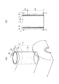
本実施の形態を図1、2に示す。図1は本発明のシリンダライナ2の斜視図(A)及び部分拡大横断面図(B),(C)を示し、図2はこのシリンダライナ2を用いたシリンダブロック4の部分斜視図(A)及び部分縦断面図(B)を示している。
[Embodiment 1]
This embodiment is shown in FIGS. FIG. 1 shows a perspective view (A) of a
<シリンダライナ2の構成>
まず、ここで図1に示したシリンダライナ2の本体2aは鋳鉄製であり、このシリンダライナ本体2aの外周面(以下「ライナ外周面」と称する)6には、括れた形状の突起8が複数形成されている。この突起8は、次の態様にて形成されている。
<Configuration of
First, the
(1)基端部8aと先端部8bとの中間に最も細い部位(括れ部8c)を有する。
(2)括れ部8cから基端部8a及び先端部8bへかけて拡径している。
(3)先端部8bに略平坦状の頂面8d(シリンダライナ2の径方向において最も外周側の面)を有する。
(1) It has the narrowest part (constricted
(2) The diameter is increased from the
(3) The
(4)突起8の間には略平滑な面(基底面8e)が形成されている。
尚、図1の(A)では基底面8eより外周側の突起8及び溶射層10をまとめて層状に示している。
(4) A substantially smooth surface (
In FIG. 1A, the
ライナ外周面6は、上下方向(軸L方向)において上部側領域6aと下部側領域6bとでは表面状態が異なる。すなわち上部側領域6aでは下部側領域6bに比較してライナ外周面6上に形成される溶射層10との密着性が高い表面状態とされている。この密着性の差は、上部側領域6a側にのみ粗面化処理がなされることにより、図1の(B)に示すごとく鋳鉄上に形成されている鉄酸化物を主成分とする黒皮11がほとんど又は完全に除去されている。下部側領域6bについては黒皮11は全く除去されていない。
The liner outer
そしてこのライナ外周面6上にはシリンダブロック4側と鋳造時に機械的あるいは冶金的に接合させるための溶射層10が形成されている。したがって図1の(B)及び(C)に示したごとく、上部側領域6aは粗面化されているので溶射層10はライナ外周面6に対する密着性が高いが、下部側領域6bは全く粗面化されていないので溶射層10はライナ外周面6に対する密着性が低くなっている。
A
<シリンダライナ2の製造工程>
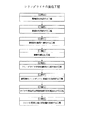
図3にシリンダライナ2の製造工程の概要を示す。
シリンダライナ2の製造では、図3に示した[工程A]〜[工程H]が実行される。
<Manufacturing process of
FIG. 3 shows an outline of the manufacturing process of the
In the manufacture of the
ここで図4に示す製造工程内容概略図を参照して、各工程の詳細について説明する。
[工程A]
耐火基材C1、粘結剤C2、及び水C3を所定の割合で配合して懸濁液C4を作成する。
Here, the details of each process will be described with reference to the schematic diagram of the contents of the manufacturing process shown in FIG.
[Step A]
A suspension C4 is prepared by blending the refractory base material C1, the binder C2 and the water C3 in a predetermined ratio.
本実施の形態においては、耐火基材C1、粘結剤C2、及び水C3の配合量として選択可能な範囲、並びに耐火基材C1の平均粒径として選択可能な範囲をそれぞれ以下のように設定している。 In the present embodiment, a range that can be selected as the blending amount of the refractory base material C1, the binder C2, and the water C3 and a range that can be selected as the average particle size of the refractory base material C1 are set as follows. is doing.
耐火基材C1の配合量 : 8質量% 〜 30質量%
粘結剤C2 の配合量 : 2質量% 〜 10質量%
水C3 の配合量 : 60質量% 〜 90質量%
耐火基材C1の平均粒径:0.02mm 〜 0.1mm
[工程B]
懸濁液C4に所定量の界面活性剤C5を添加して塗型材C6を作成する。
Blending amount of refractory base material C1: 8% by mass to 30% by mass
Compounding amount of binder C2: 2% by mass to 10% by mass
Compounding amount of water C3: 60% by mass to 90% by mass
Average particle size of the refractory base material C1: 0.02 mm to 0.1 mm
[Step B]
A predetermined amount of a surfactant C5 is added to the suspension C4 to form a coating material C6.
本実施の形態においては、界面活性剤C5の添加量として選択可能な範囲を以下のように設定している。
界面活性剤C5の添加量:0.005質量%<X≦0.1質量%(Xは添加量)
[工程C]
規定の温度に加熱されて回転状態にある金型31(鋳型)の内周面31Fに塗型材C6を噴霧塗布する。このとき、塗型材C6の層(塗型層C7)が内周面31F全周にわたって略均一の厚さに形成されるように塗型材C6の塗布が行われる。
In the present embodiment, a selectable range as the addition amount of the surfactant C5 is set as follows.
Addition amount of surfactant C5: 0.005 mass% <X ≦ 0.1 mass% (X is an addition amount)
[Step C]
The coating material C6 is spray-coated on the inner
本実施形態においては、塗型層C7の厚さとして選択可能な範囲を以下のように設定している。
塗型層C7の厚さ :0.5mm 〜 1.5mm
図5に塗型層C7における括れた形状の凹穴の形成態様を示す。
In the present embodiment, a selectable range as the thickness of the coating layer C7 is set as follows.
Thickness of the coating layer C7: 0.5 mm to 1.5 mm
FIG. 5 shows a formation mode of constricted concave holes in the coating layer C7.
図5に示すように、塗型層C7内の気泡D1に対して界面活性剤C5が作用することにより塗型層C7の内周側に凹穴D2が形成される。そして、凹穴D2が金型31の内周面31Fに突き当たることにより、塗型層C7に括れた形状の凹穴D3が形成される。
As shown in FIG. 5, the surfactant C5 acts on the bubbles D1 in the coating layer C7, whereby a concave hole D2 is formed on the inner peripheral side of the coating layer C7. Then, when the concave hole D2 abuts against the inner
[工程D]
塗型層C7が乾燥した後、回転状態にある金型31内へ鋳鉄の溶湯CIを鋳込むことによりシリンダライナ本体2aを鋳造する。このとき、塗型層C7の凹穴D3の形状に対応した形状の突起がシリンダライナ本体2aへ転写されることにより、シリンダライナ本体2aの外周面に括れた形状の突起8(図1)が形成される。
[Step D]
After the coating layer C7 is dried, the
[工程E]
溶湯CIが硬化してシリンダライナ本体2aが形成された後、塗型層C7とともにシリンダライナ本体2aを金型31から取り出す。
[Step E]
After the molten metal CI is cured and the
[工程F]
ブラスト処理装置32により塗型層C7をシリンダライナ本体2aの外周から除去する。
[Step F]
The coating layer C7 is removed from the outer periphery of the
[工程G](粗面化処理工程に相当)
粗面化装置(上記ブラスト処理装置32あるいは他のブラスト処理装置、又はウォータージェット装置)を用いて、ライナ外周面6の内で上部側領域6a(例えば上部約50mmの範囲)のみ粗面化処理する。
[Step G] (equivalent to a roughening treatment step)
Using a roughening device (the
[工程H](上下溶射工程に相当)
溶射装置33により、金属溶射材として、アルミニウム又はアルミニウム合金製のアルミ溶射材を用いてライナ外周面6全域に溶射(ワイヤー溶射、あるいはプラズマ、HVOF等の粉末溶射)を実行して溶射層10を形成する。
[Process H] (equivalent to the vertical spraying process)
The
<突起面積率>
本実施の形態においては、工程F終了後において、シリンダライナ本体2aの第1突起面積率S1及び第2突起面積率S2として選択可能な範囲を以下のように設定している。
<Protrusion area ratio>
In the present embodiment, after the process F is completed, a range that can be selected as the first protrusion area ratio S1 and the second protrusion area ratio S2 of the
第1突起面積率S1:10%以上
第2突起面積率S2:55%以下
また、以下のように設定することもできる。
1st protrusion area ratio S1: 10% or more 2nd protrusion area ratio S2: 55% or less Moreover, it can also set as follows.
第1突起面積率S1:10% 〜 50%
第2突起面積率S2:20% 〜 55%
第1突起面積率S1は、基底面8eから高さ0.4mm(基底面8eを基準とした突起8の高さ方向の距離)の平面において、単位面積当たりに占める突起8の断面積に相当する。
First protrusion area ratio S1: 10% to 50%
Second protrusion area ratio S2: 20% to 55%
The first protrusion area ratio S1 corresponds to the cross-sectional area of the
第2突起面積率S2は、基底面8eから高さ0.2mm(基底面8eを基準とした突起8の高さ方向の距離)の平面において、単位面積当たりに占める突起8の断面積に相当する。
The second protrusion area ratio S2 corresponds to the cross-sectional area of the
これら突起面積率S1,S2は3次元レーザ測定器により得られた突起8の等高線図(後述する図17,18)に基づいて得られている。尚、測定は3次元レーザ測定器に限らず他の測定器でも良い。他の実施の形態においても同じである。
These projection area ratios S1 and S2 are obtained based on contour maps (FIGS. 17 and 18 described later) of the
尚、突起8の高さと分布密度とは、工程Cにて形成された塗型層C7の凹穴D3の深さと分布密度とにより決定される。ここでは突起8の高さが0.5mm〜1.5mmであり、突起8の分布密度として、突起8の数がライナ外周面6上の1cm2 (「平方センチメートル」に相当、請求項についても同じ)当たりに5個〜60個となるように塗型層C7が形成されている。
The height and distribution density of the
<鋳鉄の組成>
本実施の形態において工程Dで溶湯CIとして用いられる鋳鉄の組成は、耐摩耗生、耐焼き付き性、及び加工性を考慮して、例えば以下のように設定することが好ましい。
<Composition of cast iron>
In the present embodiment, the composition of the cast iron used as the molten metal CI in the process D is preferably set as follows in consideration of wear resistance, seizure resistance, and workability.
T.C:2.9 質量% 〜 3.7 質量%
Si :1.6 質量% 〜 2.8 質量%
Mn :0.5 質量% 〜 1.0 質量%
P :0.05質量% 〜 0.4 質量%
また、必要に応じて以下の組成物を添加することもできる。
T. T. C: 2.9% by mass to 3.7% by mass
Si: 1.6% by mass to 2.8% by mass
Mn: 0.5% by mass to 1.0% by mass
P: 0.05% by mass to 0.4% by mass
Moreover, the following compositions can also be added as needed.
Cr :0.05質量% 〜 0.4 質量%
B :0.03質量% 〜 0.08質量%
Cu :0.3 質量% 〜 0.5 質量%
<シリンダブロック4の構成・製造>
シリンダブロック4は、シリンダライナ2に対してライナ外周面6に形成されている溶射層10を鋳ぐるむ状態で、鋳造により形成されている。シリンダブロック4を形成するための鋳造用金属としては軽合金材料が用いられる。特に、鋳造用金属としては、軽量化と共にコストを考慮して、アルミ材(アルミニウムまたはアルミニウム合金)を用いる。アルミニウム合金としては、例えば「JIS ADC10(関連規格米国ASTM A380.0)」あるいは「JIS ADC12(関連規格米国ASTM A383.0)」等を用いることができる。
Cr: 0.05% by mass to 0.4% by mass
B: 0.03 mass% to 0.08 mass%
Cu: 0.3% by mass to 0.5% by mass
<Configuration and manufacture of
The
図1に示したシリンダライナ2を鋳型内に配置してアルミ材の溶湯を鋳込む。このことにより図2に示したごとく溶射層10の外周全域がアルミ材にて鋳ぐるまれたシリンダブロック4が形成される。
The
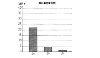
<密着性の測定>
前述した工程Gにてライナ外周面6の内で上部側領域6aのみ粗面化処理したことにより、その後の工程Hで形成された溶射層10との密着性に上部側領域6aと下部側領域6bとで差が生じていることを次のごとく測定した。
<Measurement of adhesion>
Since only the
まずFC230相当の鋳鉄にて凹穴D3(図5)を形成していない金型を用いて複数の密着強度測定用シリンダライナ本体を遠心鋳造により製造した。
これらの密着強度測定用シリンダライナ本体に対して、次のごとく3種類(A〜C)の処理により溶射層を形成した。
First, a plurality of cylinder liner main bodies for adhesion strength measurement were manufactured by centrifugal casting using a mold in which the recessed hole D3 (FIG. 5) was not formed with cast iron equivalent to FC230.
A sprayed layer was formed on these adhesion liner measuring cylinder liner bodies by three types (A to C) of treatment as follows.
A.密着強度測定用シリンダライナ本体の外周面に、粗面化処理を実施した後、溶射(Al−12Siワイヤーアーク溶射)により溶射層を形成。:[粗面化処理は、ここではショットブラスト加工による処理であるがウォータージェット加工でも良い]
B.粗面化処理無しで、密着強度測定用シリンダライナ本体を加熱した状態で、溶射(Al−12Siワイヤーアーク溶射)により溶射層を形成。:[鋳造により突起8(図1)先端が高温となっている状態での溶射をシミュレートするため]
C.加熱も粗面化処理も無い状態で、溶射(Al−12Siワイヤーアーク溶射)により溶射層を形成。
A. After the roughening treatment is performed on the outer peripheral surface of the cylinder liner body for adhesion strength measurement, a thermal spray layer is formed by thermal spraying (Al-12Si wire arc thermal spraying). : [Roughening treatment is processing by shot blasting here, but may be water jet processing]
B. A sprayed layer is formed by thermal spraying (Al-12Si wire arc spraying) with the cylinder liner body for adhesion strength measurement heated without roughening. : [To simulate thermal spraying in the state where the tip 8 (FIG. 1) has a high temperature due to casting]
C. A thermal spray layer is formed by thermal spraying (Al-12Si wire arc thermal spraying) without heating or roughening treatment.
そして、3種類A〜Cの処理により形成された密着強度測定用シリンダライナにおいて、密着強度測定用シリンダライナ本体と溶射層との間の密着強度(MPa)を引っ張り試験により測定した。この結果を、図6のグラフに示す。 In the cylinder liner for measuring the adhesion strength formed by the three types of treatments A to C, the adhesion strength (MPa) between the cylinder liner body for measuring the adhesion strength and the sprayed layer was measured by a tensile test. The result is shown in the graph of FIG.
このグラフから判るように、粗面化処理がなされないと密着性が大きく低下することが判る。このため、図1に示した本実施の形態のシリンダライナ2においては、上部側領域6aではシリンダライナ本体2aと溶射層10との間で密着性は高いが、これに比較して下部側領域6bでは密着性が十分に低くなることになる。
As can be seen from this graph, it can be seen that the adhesion is greatly reduced if the surface is not roughened. For this reason, in the
このため、シリンダブロック4の製造のために、シリンダライナ2を鋳型内に配置してアルミ材の溶湯を鋳込むと、鋳込み時の高温化とその後の冷却による熱収縮により、下部側領域6bではシリンダライナ本体2aと溶射層10との間で剥離して隙間が生じる。上部側領域6aではこの隙間が小さいかあるいは全く隙間が生じない。
For this reason, when the
上述したごとくの低い密着性により隙間が生じても、突起8の存在により、溶射層10とシリンダライナ本体2aとは強固に接合されており、溶射層10を介したシリンダライナ2とシリンダブロック4との間の接合力は十分に大きい。したがってシリンダブロック4内でのシリンダライナ2の固定やシリンダブロック4の支持によるシリンダボア2bの真円度も十分に高く維持される。
Even if a gap is generated due to the low adhesion as described above, the
そして、上記密着性の差により、シリンダライナ2の上部側領域6aでは鋳ぐるんでいるシリンダブロック4側へシリンダボア2b側の熱が伝達し易く、これに比較して下部側領域6bではシリンダブロック4側へシリンダボア2b側の熱が伝達し難くなっている。このことから高温化しやすい上部側領域6aは冷却効率が高く、高温化しにくい下部側領域6bは冷却効率は十分に低く設定できる。
Due to the difference in adhesion, heat on the cylinder bore 2b side is easily transferred to the
ここでシリンダライナ本体2a、シリンダブロック4及び溶射層10を形成している各材料の熱伝導率(W/mK)は表1のごとくである。
Here, the thermal conductivity (W / mK) of each material forming the cylinder liner

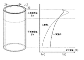
<ボア壁温の測定>
下に示すライナ外周面の状態のみ異なるシリンダライナ(a〜d)を、図2に示したごとく鋳ぐるむことにより1600cc−4気筒内燃機関用のシリンダブロックを形成する。そして内燃機関運転時でのボア壁温を実測した。
<Measurement of bore wall temperature>
The cylinder liners (a to d) that differ only in the state of the outer peripheral surface of the liner shown below are cast as shown in FIG. 2 to form a cylinder block for a 1600 cc-4 cylinder internal combustion engine. The bore wall temperature during operation of the internal combustion engine was measured.
a.比較例1:工程A〜Fにて形成された状態のシリンダライナ(粗面化処理及び溶射層形成は無し)
b.比較例2:工程A〜Hにて形成されているが、工程Gにては上部側領域6aのみでなく下部側領域6bも含めたライナ外周面の全面に均一な粗面化処理して工程Hにて溶射層を形成したシリンダライナ
c.実施例1:工程A〜Hにて形成されていると共に、工程Gにては上部側領域6aのみをショットブラスト加工にて粗面化処理したシリンダライナ
d.実施例2:工程A〜Hにて形成されていると共に、工程Gにては上部側領域6aのみをウォータージェット加工にて粗面化処理したシリンダライナ
そして、この4種類a〜dのシリンダライナを鋳ぐるんでいるシリンダブロックにおいて、シリンダブロック上面(ヘッド面)から10mm位置(上部側領域)と90mm位置(下部側領域)とで各シリンダライナのボア壁温を測定した。この結果を、図7のグラフに示す。
a. Comparative Example 1: Cylinder liner in the state formed in steps A to F (no surface roughening and no thermal spray layer formation)
b. Comparative Example 2: Although formed in steps A to H, in step G, the entire surface of the liner outer peripheral surface including not only the
グラフから判るように、比較例1,2のシリンダライナ「a」、「b」を鋳ぐるんでいるシリンダブロックは、いずれも10mm位置と90mm位置とでの温度差が大きい。実施例1,2の各シリンダライナ「c」、「d」を鋳ぐるんでいるシリンダブロックは、10mm位置と90mm位置とでの温度差が比較例1,2に比較して、ほぼ半分である。 As can be seen from the graph, the cylinder blocks in which the cylinder liners “a” and “b” of Comparative Examples 1 and 2 are cast have a large temperature difference between the 10 mm position and the 90 mm position. In the cylinder blocks in which the cylinder liners “c” and “d” of Examples 1 and 2 are cast, the temperature difference between the 10 mm position and the 90 mm position is almost half that of Comparative Examples 1 and 2. .
このため、図8で実線で示すごとく、上記c,dのシリンダライナ2では、上部側領域6aと下部側領域6bとの壁温が近づき、シリンダボア2b全域の壁温を適切な温度範囲に設定することができるようになる。尚、図8の破線は、上部側領域6aと下部側領域6bとの両方に粗面化処理を均一に実行したシリンダライナ(上記b)の温度分布の一例を示している。
Therefore, as indicated by the solid line in FIG. 8, in the
尚、粗面化処理後のシリンダライナ本体2aは請求項1,2,3に記載のシリンダライナに相当する。
以上説明した本実施の形態1によれば、以下の効果が得られる。
The
According to the first embodiment described above, the following effects can be obtained.
(イ).シリンダライナ本体2aの外周面であるライナ外周面6は、上下方向にて、中間層に相当する溶射層10との間で密着性に差が設けられている。上部側領域6aでは密着性が高く、下部側領域6bでは密着性が低い。本実施の形態では、前述した工程Gにて上部側領域6aのみに粗面化処理することにより、このような密着性の差を容易に実現している。
(I). The liner outer
内燃機関運転時においてシリンダボア2b内に発生した燃焼熱はシリンダライナ本体2aから溶射層10を介して鋳ぐるみ状態のアルミ材製シリンダブロック4側へと伝達される。この熱伝導において上部側領域6aと下部側領域6bとで上記密着性の差によりシリンダライナ本体2aから溶射層10への熱伝導状態が上部側領域6aが高く下部側領域6bが低くなる。このことによりシリンダボア2b内部からの受熱量が大きい上部側領域6aの熱がシリンダブロック4側へ排出され易くなり、これに比較してシリンダボア2b内部からの受熱量が小さい下部側領域6bの熱はシリンダブロック4側へ排出され難くなる。
The combustion heat generated in the cylinder bore 2b during operation of the internal combustion engine is transmitted from the
したがってシリンダボア2bの上部側と下部側とでシリンダボア2bの壁温が近づき、シリンダボア2b内全域の壁温を適切な温度範囲に設定できるようになる。
そしてライナ外周面6における密着性が低下しても、前述した括れた形状の突起8がライナ外周面6全域に前述した分布状態で形成されているため、シリンダライナ本体2aと溶射層10との接合力、及び溶射層10を介してのシリンダライナ本体2aとシリンダブロック4との接合力は十分に大きい。このことによりシリンダボア2bの真円度を十分に高く維持できる。
Therefore, the wall temperature of the cylinder bore 2b approaches between the upper side and the lower side of the
Even when the adhesion on the liner outer
このシリンダライナ2をアルミ材にて鋳ぐるんで形成されたシリンダブロック4は、上部側領域6aでは、図9の(A)に示すごとく、シリンダボア2bの壁温低下によるエンジンオイル消費が向上することから、シリンダボア2b内に配置するピストンのリング張力を低下することができる。又、(B)に示すごとく下部側領域6bではシリンダボア2bの壁温上昇によるシリンダボア2bにおける油膜粘性低下を生じる。
As shown in FIG. 9A, the
これらのことから内燃機関の機械損失が低下し、更に上述したごとくシリンダボア2bの真円度が維持されることから排気損失や機械損失による燃費悪化を防止して、良好な燃費状態を実現できる。
As a result, the mechanical loss of the internal combustion engine is reduced, and the roundness of the
[実施の形態2]
本実施の形態では、前記実施の形態1の工程A〜Hの内の工程G,Hの代わりに、図10〜13にて示す工程I,Jを実行する。
[Embodiment 2]
In the present embodiment, steps I and J shown in FIGS. 10 to 13 are executed instead of steps G and H in steps A to H of the first embodiment.
[工程I]
前記実施の形態1と同じ工程A〜Fにて形成されたシリンダライナ本体102aを、図10に示すごとく、粗面化装置(前記ブラスト処理装置32あるいは他のブラスト処理装置、又はウォータージェット装置)132を用いて、ライナ外周面106の全領域を均一に粗面化処理する。
[Step I]
The cylinder liner
[工程J]
上記工程Iにて粗面化処理されたシリンダライナ本体102aに対して、図11,12に示すごとく、部分工程J−1,J−2にて、ライナ外周面106全域に、溶射装置から溶射(ワイヤー溶射、あるいはプラズマ、HVOF等の粉末溶射)を実行して溶射層116(図13)を形成する。尚、溶射材としては、アルミニウム又はアルミニウム合金製のアルミ溶射材を用いている。
[Process J]
As shown in FIGS. 11 and 12, as shown in FIGS. 11 and 12, the cylinder liner
溶射層116の形成手順である部分工程J−1,J−2について説明する。
[部分工程J−1](分別溶射工程に相当)
図11に実線矢印にて示すごとく、溶射ガン133aを、溶射スタート位置Stから、上部側領域106a全域に溶融溶射粒子133bが衝突する位置Mまで、回転しているシリンダライナ本体102aの軸Lに沿って、1パスで目標溶射層厚が形成される速度で移動させる。そして一時的に位置Mにて溶射ガン133aから溶射を継続したまま移動を停止する。
The partial processes J-1 and J-2 which are the formation procedure of the sprayed
[Partial process J-1] (equivalent to fractional spraying process)
As indicated by solid arrows in FIG. 11, the
この時、同時に、ヒューム(微小酸化物、微細凝固粒子などからなり、密着を阻害する物質に相当)133cが溶融溶射粒子133bの周囲(溶融溶射粒子周辺部に相当)に噴射される。しかし、下部側領域106bにはヒューム133cの衝突を防止するマスキングはなされておらず、直接、ヒューム133cが下部側領域106bに衝突して堆積する。
At the same time, fume (corresponding to a substance consisting of fine oxides, finely solidified particles, etc., which inhibits adhesion) 133c is injected around the molten sprayed
この停止状態での溶射期間は、下部側領域106bに堆積するヒューム133cにより目的とする密着性低下が生じれば良く、予め実験にて決定されている。このことにより図13の(a1)に示すごとく上部側領域106aには部分溶射層112が、図13の(b1)に示すごとく下部側領域106bにはヒューム堆積層114が形成される。
The thermal spraying period in the stopped state is determined by experiments in advance as long as the target adhesion deterioration is caused by the
[部分工程J−2](上下溶射工程に相当)
部分工程J−1において位置Mで停止した状態での溶射期間が終了した後に、図12に示すごとく、溶射ガン133aを軸Lに沿って複数パスで移動させて、上部側領域106a及び下部側領域106b(主として下部側領域106b)に対して溶射し、その後、溶射を終了する。図12では実線矢印で示すごとく5パスで溶射を終了している。
[Partial process J-2] (equivalent to vertical spraying process)
After the spraying period in the state stopped at the position M in the partial process J-1, as shown in FIG. 12, the
この複数パスの溶射により、上部側領域106aの一部も含めてライナ外周面106の全域にほぼ均一に目標溶射層厚の溶射層116が形成される。このことにより図13の(a2)、(b2)に示すごとくライナ外周面106全域に最上位層として溶射層116が形成される。これと共に下部側領域106bについては溶射層116の下に、部分工程J−1にて形成されたヒューム堆積層114が存在する状態となる。こうして本実施の形態のシリンダライナが完成する。
By this multiple-pass spraying, a sprayed
尚、部分工程J−2においてもヒューム133cがライナ外周面106に衝突するが、シリンダライナ本体102a上に直接衝突しておらず、塗り重ねられる溶融溶射粒子133bにより溶射層116内に分散されるので、密着性には影響しない。
In the partial process J-2, the
<密着性の測定>
ヒューム堆積層114の有無による溶射層116の密着性を調べるために、突起8(図1)の存在しないシリンダライナを2つ準備した。そして1つのシリンダライナJaには、部分工程J−1,J−2にて上部側領域106aに対して実行した溶射処理により、図13の(a2)のごとくの溶射層116を形成した。他のシリンダライナJbには下部側領域106bに対して実行した溶射処理により、図13の(b2)のごとくのヒューム堆積層114と溶射層116とを形成した。
<Measurement of adhesion>
In order to examine the adhesion of the
これらのシリンダライナJa,Jbにおいて形成された溶射層116の引っ張り強度(MPa)を測定した結果を図14に示す。図示するごとく、ヒューム堆積層114が溶射層116の下、すなわちライナ外周面106と溶射層116との間に存在することにより、ライナ外周面106と溶射層116との密着性が大きく低下していることが判る。尚、本実施の形態のシリンダライナを鋳込んだシリンダブロックにおいては、ヒューム堆積層114と溶射層116とを介して接続される下部側領域106bにおいても、シリンダライナとシリンダブロックとは、突起8の存在により十分に接合されていた。
FIG. 14 shows the results of measuring the tensile strength (MPa) of the sprayed
尚、部分工程J−1後のシリンダライナ本体102aは請求項1,2,3に記載のシリンダライナに相当する。
以上説明した本実施の形態2によれば、以下の効果が得られる。
The
According to the second embodiment described above, the following effects can be obtained.
(イ).ライナ外周面106は、上部側領域106aでは密着性が高く、下部側領域106bでは密着性が低くされている。本実施の形態では、工程Iにてライナ外周面106の全領域を均一に粗面化処理しているが、工程Jにて下部側領域106bのみに、溶射層116とライナ外周面106との間にヒューム堆積層114を形成している。このことにより上部側領域106aと下部側領域106bとで密着性の差を容易に実現している。
(I). The liner outer
前記実施の形態1にても述べたごとく上部側領域106aと下部側領域106bとで上記密着性の差により、シリンダライナ本体102aから溶射層116への熱伝導性が上部側領域106aでは高いが、下部側領域106bで低くなる。このことにより、シリンダボア102bの上部側領域と下部側領域とでシリンダボア102bの壁温を近づけて、シリンダボア102b内全域の壁温を適切な温度範囲に設定できるようになる。
As described in the first embodiment, the thermal conductivity from the
そして下部側領域106bにおいてヒューム堆積層114により溶射層116の密着性が低下しても、前述したごとくの形状の突起8がライナ外周面106全域に前述したごとくの分布状態で形成されている。このためシリンダライナ本体102aと溶射層116との接合力、及び溶射層116を介してのシリンダライナ本体102aとシリンダブロックとの接合力は十分に大きい。このことによりシリンダボア102bの真円度を十分に高く維持できる。
Even if the adhesion of the
こうして前記実施の形態1と同様に排気損失や機械損失による燃費悪化を防止して、良好な燃費状態を実現できる。
(ロ).特に溶射処理時に溶射層116の一部(部分溶射層112)の形成と同時にヒューム堆積層114が形成できるので、効率的に上部側領域106aと下部側領域106bとで密着性に差を設ける処理ができる。
In this way, as in the first embodiment, it is possible to prevent deterioration in fuel consumption due to exhaust loss or mechanical loss, and realize a good fuel consumption state.
(B). In particular, since the
又、ヒューム堆積層114上には溶射層116が形成されてシリンダライナとして完成することから、剥がれやすいヒューム堆積層114が溶射層116により保護されている。したがってシリンダライナの運搬移動時においてもヒューム堆積層114が剥がれることが無く、シリンダライナの製造後からシリンダブロックに鋳込むまでの期間において密着性の差に変化が生じることを防止できる。
Further, since the sprayed
[実施の形態3]
本実施の形態では、前記実施の形態2の部分工程J−1にて、図15に示すごとく、排気ダクト118(吸引装置に相当)によりシリンダライナ本体102a周辺の空気を、上部側領域106a側から下部側領域106b側へと吸引している状態で、部分溶射層112とヒューム堆積層114とを形成する。このことにより下部側領域106bに、より均一にかつ確実にヒューム133cを衝突させることができる。
[Embodiment 3]
In the present embodiment, as shown in FIG. 15, in the partial process J-1 of the second embodiment, the air around the cylinder liner
他の工程は前記実施の形態2と同じである。
<密着性の測定>
本実施の形態の手法により形成されたヒューム堆積層114の有無による溶射層116の密着性を調べるために、突起8の存在しないシリンダライナJcを準備した。このシリンダライナJcに対して、図15に示した部分工程J−1と、前記実施の形態2の図12に示した部分工程J−2により、下部側領域106bに実行する溶射処理と同じ処理を行い、ヒューム堆積層114と溶射層116とを形成した。
Other steps are the same as those in the second embodiment.
<Measurement of adhesion>
In order to examine the adhesion of the
このシリンダライナJcに形成された溶射層116の引っ張り強度(MPa)を測定した結果を前記実施の形態2のシリンダライナJa,Jbのデータと共に図16に示す。図示するごとく、シリンダライナJcの場合は、前記実施の形態2のシリンダライナJbに比較してもヒューム堆積層114が、より十分に下部側領域106b全域に渡って形成されているので、シリンダライナJbよりも更に密着性が大きく低下していることが判る。
FIG. 16 shows the results of measuring the tensile strength (MPa) of the sprayed
そして本実施の形態のシリンダライナを鋳込んだシリンダブロックにおいては、下部側領域106bにおいて大きく密着性が低下していても、シリンダライナとシリンダブロックとは、突起8の存在により十分に接合されていた。
In the cylinder block in which the cylinder liner of the present embodiment is cast, the cylinder liner and the cylinder block are sufficiently joined by the presence of the
尚、部分工程J−1後のシリンダライナ本体102aは請求項1,2,3に記載のシリンダライナに相当する。
以上説明した本実施の形態3によれば、以下の効果が得られる。
The
According to the third embodiment described above, the following effects can be obtained.
(イ).前記実施の形態2の効果を生じると共に、下部側領域106bにおけるヒューム堆積層114の形成を確実なものとできる。又、排気ダクト118の吸引力の調節によりヒューム堆積層114の厚さをコントロールできるので、密着性及びこれによる熱伝導状態の差も、更に高精度に調節することが可能となる。
(I). In addition to the effects of the second embodiment, the formation of the
[突起の等高線図の説明]
ここで、3次元レーザ測定器にて得られた突起8の等高線図について説明する。
<突起8の等高線図>
図17を参照して、突起8の等高線の測定態様について説明する。本等高線図の作成に当たっては、まず等高線測定用のテストピースを、基底面8e(ライナ外周面6,106)が非接触式の3次元レーザ測定器と対向するように試験台へセットする。そしてライナ外周面6,106に対して略直行するようにレーザ光を照射して測定する。この測定結果を画像処理装置に取り込み、図17の(a)に示すごとく突起8の等高線図とした。
[Explanation of contour map of protrusions]
Here, the contour map of the
<Contour map of
With reference to FIG. 17, the measurement aspect of the contour line of the
図17の(b)はライナ外周面6,106と等高線hとの関係を示す。図示するごとく等高線hはライナ外周面6,106から突起8の高さ方向(矢印Y方向)における所定距離毎に等高線図上へ表示される。以降では、ライナ外周面6,106を基準とした矢印Y方向への距離を「測定高さ」とする。
FIG. 17B shows the relationship between the liner outer
尚、図17においては、等高線hを0.2mm間隔毎に表示した等高線図を示しているが、等高線hの間隔は適宜の値に設定することができる。
〔a〕第1突起面積率S1
図18の(a)に測定高さ0.4mm未満の等高線hを非表示にしたときの等高線図(第1等高線図)を示す。ここでは、図示した等高線図の面積(W1×W2)を、第1突起面積率S1の測定に際しての単位面積としている。
Note that FIG. 17 shows a contour map in which the contour lines h are displayed at intervals of 0.2 mm, but the interval between the contour lines h can be set to an appropriate value.
[A] First protrusion area ratio S1
FIG. 18 (a) shows a contour map (first contour map) when the contour line h having a measured height of less than 0.4 mm is not displayed. Here, the area (W1 × W2) of the contour map shown in the figure is used as a unit area when measuring the first protrusion area ratio S1.
第1等高線図において、等高線h4に囲まれた領域R4の面積(図中の斜線ハッチング部分の面積SR4)は、測定高さ0.4mmの平面に属する1つの突起の断面積(第1突起断面積)に相当する。また、第1等高線図における領域R4の数(領域数N4)は、第1等高線図内に存在している突起8の数(突起数N1)に相当する。 In the first contour map, the area of the region R4 surrounded by the contour line h4 (the area SR4 of the hatched portion in the figure) is the cross-sectional area of the one projection belonging to the plane having the measurement height of 0.4 mm (the first projection section). Area). Further, the number of regions R4 (region number N4) in the first contour map corresponds to the number of protrusions 8 (projection number N1) existing in the first contour diagram.
第1突起面積率S1は、等高線図の面積(W1×W2)に占める領域R4の合計面積(SR4×N4)の割合として算出される。即ち、第1突起面積率S1は、測定高さ0.4mmの平面において、単位面積当たりに占める第1突起断面積の合計面積に相当する。 The first protrusion area ratio S1 is calculated as a ratio of the total area (SR4 × N4) of the region R4 to the area (W1 × W2) of the contour map. That is, the first protrusion area ratio S1 corresponds to the total area of the first protrusion cross-sectional areas occupying per unit area on a plane having a measurement height of 0.4 mm.
第1突起面積率S1は、下記計算式
S1=(SR4×N4)/(W1×W2)×100 [%]
により示すことができる。
The first protrusion area ratio S1 is calculated by the following formula: S1 = (SR4 × N4) / (W1 × W2) × 100 [%]
Can be shown.
〔b〕第2突起面積率S2
図18の(b)に測定高さ0.2mm未満の等高線hを非表示にしたときの等高線図(第2等高線図)を示す。ここでは、等高線図の面積(W1×W2)を第2突起面積率S2の測定に際しての単位面積としている。
[B] Second protrusion area ratio S2
FIG. 18B shows a contour map (second contour map) when the contour line h having a measurement height of less than 0.2 mm is not displayed. Here, the area (W1 × W2) of the contour map is used as a unit area when measuring the second protrusion area ratio S2.
第2等高線図において、等高線h2に囲まれた領域R2の面積(図中の斜線ハッチング部分の面積SR2)は、測定高さ0.2mmの平面に属する1つの突起の断面積(第2突起断面積)に相当する。また、第2等高線図における領域R2の数(領域数N2)は、第2等高線図内に存在している突起8の数に相当する。ここでは第2等高線図の面積は第1等高線図の面積と同じであるので、突起8の数=突起数N1である。
In the second contour map, the area of the region R2 surrounded by the contour line h2 (the area SR2 of the hatched portion in the figure) is the cross-sectional area of one protrusion belonging to the plane having a measurement height of 0.2 mm (second protrusion section). Area). The number of regions R2 (region number N2) in the second contour map corresponds to the number of
第2突起面積率S2は、等高線図の面積(W1×W2)に占める領域R2の合計面積(SR2×N2)の割合として算出される。即ち、第2突起面積率S2は、測定高さ0.2mmの平面において、単位面積当たりに占める第2突起断面積の合計面積に相当する。 The second protrusion area ratio S2 is calculated as a ratio of the total area (SR2 × N2) of the region R2 to the area (W1 × W2) of the contour map. That is, the second protrusion area ratio S2 corresponds to the total area of the second protrusion cross-sectional areas per unit area in a plane having a measurement height of 0.2 mm.
第2突起面積率S2は、下記計算式
S2=(SR2×N2)/(W1×W2)×100 [%]
により示すことができる。
The second projection area ratio S2 is calculated by the following formula: S2 = (SR2 × N2) / (W1 × W2) × 100 [%]
Can be shown.
〔c〕第1,2突起断面積
第1突起断面積は測定高さ0.4mmの平面に属する1つの突起の断面積として、第2突起断面積は測定高さ0.2mmの平面に属する1つの突起の断面積として、それぞれ等高線図から算出される。例えば、等高線図の画像処理を通じて、第1等高線図(図18の(a))の領域R4の面積を算出することで第1突起断面積を把握することができ、第2等高線図(図18の(b))の領域R2の面積を算出することで第2突起断面積を把握することができる。
[C] First and second protrusion cross-sectional areas The first protrusion cross-sectional area is a cross-sectional area of one protrusion belonging to a plane having a measurement height of 0.4 mm, and the second protrusion cross-sectional area is a plane having a measurement height of 0.2 mm The cross-sectional area of one protrusion is calculated from the contour map. For example, by calculating the area of the region R4 of the first contour map (FIG. 18A) through image processing of the contour map, the first protrusion cross-sectional area can be grasped, and the second contour map (FIG. 18). By calculating the area of the region R2 in (b)), the cross-sectional area of the second protrusion can be grasped.
〔d〕突起数
突起数N1は、シリンダライナのライナ外周面6,106の単位面積(1cm2)当たりに形成されている突起8の数として、等高線図から算出される。例えば、等高線図の画像処理を通じて、第1等高線図(図18(a))の領域R4の数(領域数N4)算出することで突起数N1を把握することができる。
[D] Number of projections The number of projections N1 is calculated from the contour map as the number of
第1突起面積率S1が10%以上のシリンダライナを適用したシリンダブロックと、第1突起面積率S1が10%未満のシリンダライナを適用したシリンダブロックとにおけるボアの変形量を比較したところ、後者の変形量は前者の変形量の3倍以上となる場合があることが確認された。 When comparing the amount of deformation of the bore between the cylinder block to which the cylinder liner having the first protrusion area ratio S1 of 10% or more and the cylinder block to which the cylinder liner having the first protrusion area ratio S1 of less than 10% is applied, the latter It has been confirmed that the amount of deformation may be more than three times the amount of deformation of the former.
第2突起面積率S2が55%よりも大きいシリンダライナでは、空隙率が急激に上昇する。ここで空隙率とは、シリンダライナとシリンダブロックとの境界に形成されている空隙の面積が境界断面に占める割合である。 In the cylinder liner in which the second protrusion area ratio S2 is larger than 55%, the void ratio rapidly increases. Here, the porosity is the ratio of the area of the air gap formed at the boundary between the cylinder liner and the cylinder block to the boundary cross section.
これらの結果から、第1突起面積率S1が10%以上、且つ第2突起面積率S2が55%以下のシリンダライナをシリンダブロックへ適用することにより、ブロック材とシリンダライナとの接合強度及び密着性の向上を好適に実現することができるようになる。 From these results, by applying a cylinder liner having a first protrusion area ratio S1 of 10% or more and a second protrusion area ratio S2 of 55% or less to the cylinder block, the bonding strength and adhesion between the block material and the cylinder liner are improved. The improvement in performance can be preferably realized.
なお、第1突起面積率S1の上限を50%とすることにより、第2突起面積率S2を55%以下にすることができる。第2突起面積率S2の下限を20%とすることにより、第1突起面積率S1を10%以上にすることができる。 Note that by setting the upper limit of the first protrusion area ratio S1 to 50%, the second protrusion area ratio S2 can be set to 55% or less. By setting the lower limit of the second protrusion area ratio S2 to 20%, the first protrusion area ratio S1 can be set to 10% or more.
[その他の実施の形態]
(1).図17,18に示した等高線図において等高線h4に囲まれた領域R4がそれぞれ独立するように突起8を形成(測定高さ0.4mmの位置において突起8同士がそれぞれ独立するようにシリンダライナを形成)しても良い。このようにすると、シリンダブロックとシリンダライナとの接合力を更に向上させることができる。
[Other embodiments]
(1). 17 and 18, the
更に、測定高さ0.4mmの位置において、突起8の1つ当たりの面積を0.2mm2〜3.0mm2(「平方ミリメートル」に相当、請求項についても同じ)に設定すると、製造工程での突起8の破損と接合力低下とを抑制することができる。
Further, when the area per
(2).前記実施の形態1において、粗面化処理工程において、上部側領域6aのみ粗面化処理がなされていたが、上部側領域6aを強い粗面化処理とし、これよりも弱い粗面化処理を下部側領域6bに実行しても良い。このことによって上部側領域6aと下部側領域6bとにおいて密着性及び熱伝導性の差を調節しても良い。
(2). In the first embodiment, in the roughening treatment step, only the
(3).前記実施の形態2,3において下部側領域106bのみにヒューム堆積層114を形成していたが、上部側領域106aに下部側領域106bよりも薄いヒューム堆積層を設けても良い。このことによって上部側領域106aと下部側領域106bとにおいて密着性及び熱伝導性の差を調節しても良い。
(3). In the second and third embodiments, the
(4).前記各実施の形態では、シリンダライナ本体2a,102aのライナ外周面6,106には溶射層10,116が存在することにより、シリンダライナとして形成されていたが、溶射層10,116を設けないでシリンダライナとして用いても良い。
(4). In each of the above embodiments, the thermal spray layers 10 and 116 are formed on the liner outer
すなわち、前記実施の形態1の場合は、シリンダライナ本体2aに対して工程Gにて上部側領域6aのみを粗面化処理したものをシリンダライナとしてシリンダブロックに鋳込んでも良い。前記実施の形態2,3の場合には、部分工程J−1にて下部側領域106bにヒューム堆積層114を形成したものをシリンダライナとしてシリンダブロックに鋳込んでも良い。
That is, in the case of the first embodiment, the cylinder liner
このことによっても、シリンダライナの上部側領域106aと下部側領域106bとで、シリンダブロックに対する密着性の差から、熱伝導状態の差が生じると共に、突起8によりシリンダブロックとの接合力は十分に大きいので、各実施の形態と同様な効果を生じさせることができる。
This also causes a difference in heat conduction between the
(5).前記実施の形態1の粗面化の程度は上下方向で2段に分けられていたが、3段以上の複数段に分けても良い。例えば、上部側、中間部側、下部側と3段の領域に分けて、上中下と次第に粗面化の程度を低下しても良く、この場合、下部側領域では全く粗面化しなくても良い。 (5). Although the degree of roughening in the first embodiment is divided into two stages in the vertical direction, it may be divided into a plurality of stages of three or more stages. For example, the upper side, the middle side, and the lower side may be divided into three regions, and the degree of surface roughening may be gradually reduced. In this case, the lower side region is not roughened at all. Also good.
又、前記実施の形態2,3のヒューム堆積の程度についても、上下方向で2段に分けられていたが、3段以上の複数段に分けても良い。例えば、上部側、中間部側、下部側と3段の領域に分けて、上中下と次第にヒューム堆積層の厚さを厚く、すなわちヒュームを多く堆積させても良く、この場合、上部側領域では全くヒュームを堆積させなくても良い。 Further, the degree of fume deposition in the second and third embodiments is also divided into two stages in the vertical direction, but it may be divided into a plurality of stages of three or more stages. For example, the upper side, the middle side, and the lower side may be divided into three regions, and the thickness of the fume deposition layer may be gradually increased, that is, a large amount of fume may be deposited. Then, it is not necessary to deposit fume at all.
(6).各実施の形態における突起は、
(a)突起の高さが0.5mm〜1.5mm
(b)突起の数がライナ外周面上の1cm2 当たりに5個〜60個
(c)3次元レーザ測定器により突起の高さ方向からライナ外周面を測定して得られる突起の等高線図において、高さ0.4mmの等高線により囲まれる領域の面積率をS1としたとき、面積率S1が10%以上
(d)3次元レーザ測定器により突起の高さ方向からライナ外周面を測定して得られる突起の等高線図において、高さ0.2mmの等高線により囲まれる領域の面積率をS2としたとき、面積率S2が55%以下
上記(a)〜(d)の全ての条件を満たしていた。
(6). The protrusion in each embodiment is
(A) The height of the protrusion is 0.5 mm to 1.5 mm
(B) The number of protrusions is 5 to 60 per 1 cm @ 2 on the outer peripheral surface of the liner. (C) In the contour map of the protrusion obtained by measuring the outer peripheral surface of the liner from the height direction of the protrusion with a three-dimensional laser measuring instrument. When the area ratio of the region surrounded by the contour line having a height of 0.4 mm is S1, the area ratio S1 is 10% or more. (D) Obtained by measuring the outer peripheral surface of the liner from the height direction of the protrusion with a three-dimensional laser measuring instrument. In the contour map of the projection to be obtained, when the area ratio of the region surrounded by the contour line having a height of 0.2 mm is S2, the area ratio S2 is 55% or less. All the conditions (a) to (d) were satisfied. .
あるいは、
(a)突起の高さが0.5mm〜1.5mm
(b)突起の数がライナ外周面上の1cm2 当たりに5個〜60個
(c)3次元レーザ測定器により突起の高さ方向からライナ外周面を測定して得られる突起の等高線図において、高さ0.4mmの等高線により囲まれる領域の面積率をS1としたとき、面積率S1が10%〜50%
(d)3次元レーザ測定器により突起の高さ方向からライナ外周面を測定して得られる突起の等高線図において、高さ0.2mmの等高線により囲まれる領域の面積率をS2としたとき、面積率S2が20%〜55%
上記(a)〜(d)の全ての条件を満たしていた。
Or
(A) The height of the protrusion is 0.5 mm to 1.5 mm
(B) The number of protrusions is 5 to 60 per 1 cm @ 2 on the outer peripheral surface of the liner. (C) In the contour map of the protrusion obtained by measuring the outer peripheral surface of the liner from the height direction of the protrusion with a three-dimensional laser measuring instrument. When the area ratio of the region surrounded by the contour line having a height of 0.4 mm is S1, the area ratio S1 is 10% to 50%.
(D) In the contour map of the projection obtained by measuring the outer peripheral surface of the liner from the height direction of the projection with a three-dimensional laser measuring instrument, when the area ratio of the region surrounded by the contour line having a height of 0.2 mm is S2, Area ratio S2 is 20% to 55%
All the conditions (a) to (d) were satisfied.
これ以外に、
(a)突起の高さが0.5mm〜1.5mm
(b)突起の数がライナ外周面上の1cm2 当たりに5個〜60個
これら(a)及び(b)の条件の少なくとも一方を満たした突起でも良く、シリンダライナの上下方向のいずれの位置にてもシリンダブロックとの接合力を十分に生じさせることができる。
Besides this,
(A) The height of the protrusion is 0.5 mm to 1.5 mm
(B) The number of protrusions is 5 to 60 per 1 cm @ 2 on the outer peripheral surface of the liner. The protrusions satisfy at least one of the conditions (a) and (b), and may be located at any position in the vertical direction of the cylinder liner. However, it is possible to sufficiently generate the joining force with the cylinder block.
又、(a)及び(b)の条件の少なくとも一方と、前記(c)及び(d)の条件を組み合わせた突起でも良く、シリンダライナとシリンダブロックとの接合力を十分に生じさせることができる。 Further, the projection may be a combination of at least one of the conditions (a) and (b) and the conditions (c) and (d), and can sufficiently generate a joining force between the cylinder liner and the cylinder block. .
又、上記各条件を満たしていなくても括れた形状の複数の突起が外周面から突出していれば、シリンダブロックとの接合力を従来よりも十分に生じさせることができる。 Further, even if the above conditions are not satisfied, if a plurality of constricted protrusions protrude from the outer peripheral surface, a joining force with the cylinder block can be sufficiently generated as compared with the conventional case.
2…シリンダライナ、2a…シリンダライナ本体、2b…シリンダボア、4…シリンダブロック、6…ライナ外周面、6a…上部側領域、6b…下部側領域、8…突起、8a…基端部、8b…先端部、8c…括れ部、8d…頂面、8e…基底面、10…溶射層、11…黒皮、31…金型、31F…内周面、32…ブラスト処理装置、33…溶射装置、102a…シリンダライナ本体、102b…シリンダボア、106…ライナ外周面、106a…上部側領域、106b…下部側領域、112…部分溶射層、114…ヒューム堆積層、116…溶射層、118…排気ダクト、132…粗面化装置、133a…溶射ガン、133b…溶融溶射粒子、133c…ヒューム、C1…耐火基材、C2…粘結剤、C3…水、C4…懸濁液、C5…界面活性剤、C6…塗型材、C7…塗型層、CI…溶湯、D1…気泡、D2,D3…凹穴、Ja,Jb,Jc…シリンダライナ、L…軸。
DESCRIPTION OF
Claims (22)
シリンダライナ上下方向にて外周面とシリンダブロック又は中間層との密着性に差が設けられ、且つシリンダライナ上部側での前記密着性がシリンダライナ下部側での前記密着性よりも高く設定される
ことを特徴とするシリンダライナ。 In a cylinder liner in which a plurality of constricted protrusions are formed on the outer peripheral surface, and the outer peripheral surface is cast by a casting metal directly or through an intermediate layer when casting a cylinder block of an internal combustion engine,
The difference is provided to the adhesion between the outer peripheral surface and the cylinder block or intermediate layer in the cylinder liner vertically, and the adhesion at the cylinder liner upper portion is set higher than the adhesion at the cylinder liner lower portion A cylinder liner characterized by that.
前記密着性の違いは、シリンダライナ上部側の外周面のみに粗面化処理が施されることにより維持される
ことを特徴とするシリンダライナ。 The cylinder liner according to claim 1,
The adhesion of the differences, a cylinder liner, characterized in that it is maintained by the roughening process is performed on only the outer peripheral surface of the cylinder liner upper portion.
前記密着性の違いは、シリンダライナ上部側の外周面にシリンダライナ下部側の外周面よりも強い度合の粗面化処理が施されることにより維持される
ことを特徴とするシリンダライナ。 The cylinder liner according to claim 1,
The cylinder liner is characterized in that the difference in adhesion is maintained by subjecting the outer peripheral surface on the upper side of the cylinder liner to a roughening treatment to a higher degree than the outer peripheral surface on the lower side of the cylinder liner.
前記粗面化処理としてショットブラスト加工又はウォータージェット加工が施される
ことを特徴とするシリンダライナ。 The cylinder liner according to claim 2 or 3 ,
A cylinder liner characterized by being subjected to shot blasting or water jet machining as the roughening treatment.
シリンダライナ上下方向にて外周面とシリンダブロック又は中間層との密着性に差が設けられ、且つシリンダライナ下部側での前記密着性がシリンダライナ上部側での前記密着性よりも低く設定されるものであって、
この密着性の違いは、外周面とシリンダブロック又は中間層との密着を阻害する物質について、これがシリンダライナ上部側の外周面よりもシリンダライナ下部側の外周面に多く堆積していることにより維持される
ことを特徴とするシリンダライナ。 In a cylinder liner in which a plurality of constricted protrusions are formed on the outer peripheral surface, and the outer peripheral surface is cast by a casting metal directly or through an intermediate layer when casting a cylinder block of an internal combustion engine,
There is a difference in the adhesion between the outer peripheral surface and the cylinder block or the intermediate layer in the vertical direction of the cylinder liner, and the adhesion at the lower side of the cylinder liner is set lower than the adhesion at the upper side of the cylinder liner. And
This difference in adhesion is maintained by the fact that substances that obstruct the adhesion between the outer peripheral surface and the cylinder block or intermediate layer are deposited more on the outer peripheral surface on the cylinder liner lower side than on the outer peripheral surface on the cylinder liner upper side. Cylinder liner characterized by being made.
シリンダライナ上下方向にて外周面とシリンダブロック又は中間層との密着性に差が設けられ、且つシリンダライナ下部側での前記密着性がシリンダライナ上部側での前記密着性よりも低く設定されるものであって、
この密着性の違いは、外周面とシリンダブロック又は中間層との密着を阻害する物質について、これがシリンダライナ下部側の外周面のみに堆積していることにより維持される
ことを特徴とするシリンダライナ。 In a cylinder liner in which a plurality of constricted protrusions are formed on the outer peripheral surface, and the outer peripheral surface is cast by a casting metal directly or through an intermediate layer when casting a cylinder block of an internal combustion engine,
There is a difference in the adhesion between the outer peripheral surface and the cylinder block or the intermediate layer in the vertical direction of the cylinder liner, and the adhesion at the lower side of the cylinder liner is set lower than the adhesion at the upper side of the cylinder liner. And
This difference in adhesion is maintained by the fact that substances that obstruct the adhesion between the outer peripheral surface and the cylinder block or the intermediate layer are deposited only on the outer peripheral surface on the lower side of the cylinder liner. .
前記密着を阻害する物質として溶射時に生じるヒュームが堆積している
ことを特徴とするシリンダライナ。 The cylinder liner according to claim 5 or 6 ,
A cylinder liner characterized in that fumes generated during thermal spraying are deposited as a substance that inhibits the adhesion.
前記密着を阻害する物質としてのヒューム上に前記中間層としての溶射層が形成される
ことを特徴とするシリンダライナ。 The cylinder liner according to claim 7 ,
A thermal spray layer as the intermediate layer is formed on a fume as a substance that inhibits the adhesion.
次の(a)及び(b)の少なくとも一方の条件が満たされる
(a)「前記突起の高さが0.5mm〜1.5mmの範囲にある」
(b)「前記突起の数が前記外周面上の1cm2当たり5個〜60個の範囲にある」
ことを特徴とするシリンダライナ。 In the cylinder liner according to any one of claims 1 to 8,
At least one of the following conditions (a) and (b) is satisfied: (a) “the height of the protrusion is in the range of 0.5 mm to 1.5 mm”
(B) “The number of the protrusions is in the range of 5 to 60 per cm 2 on the outer peripheral surface”
A cylinder liner characterized by that.
次の(c)及び(d)の条件がさらに満たされる
(c)「前記突起の高さ方向から前記外周面を測定して得られる前記突起の等高線図において、高さ0.4mmの等高線により囲まれる領域の面積率をS1としたとき、面積率S1が10%以上の範囲にある」
(d)「前記突起の高さ方向から前記外周面を測定して得られる前記突起の等高線図において、高さ0.2mmの等高線により囲まれる領域の面積率をS2としたとき、面積率S2が55%以下の範囲にある」
ことを特徴とするシリンダライナ。 The cylinder liner according to claim 9 , wherein
The following conditions (c) and (d) are further satisfied: (c) “In the contour map of the protrusion obtained by measuring the outer peripheral surface from the height direction of the protrusion, a contour line having a height of 0.4 mm is used. When the area ratio of the enclosed region is S1, the area ratio S1 is in the range of 10% or more.
(D) “In the contour map of the projection obtained by measuring the outer peripheral surface from the height direction of the projection, when the area ratio of the region surrounded by the contour line having a height of 0.2 mm is S2, the area ratio S2 Is in the range of 55% or less. "
A cylinder liner characterized by that.
次の(c)及び(d)の条件がさらに満たされる
(c)「前記突起の高さ方向から前記外周面を測定して得られる前記突起の等高線図において、高さ0.4mmの等高線により囲まれる領域の面積率をS1としたとき、面積率S1が10%〜50%の範囲にある」
(d)「前記突起の高さ方向から前記外周面を測定して得られる前記突起の等高線図において、高さ0.2mmの等高線により囲まれる領域の面積率をS2としたとき、面積率S2が20%〜55%の範囲にある」
ことを特徴とするシリンダライナ。 The cylinder liner according to claim 9 , wherein
The following conditions (c) and (d) are further satisfied: (c) “In the contour map of the protrusion obtained by measuring the outer peripheral surface from the height direction of the protrusion, a contour line having a height of 0.4 mm is used. When the area ratio of the enclosed region is S1, the area ratio S1 is in the range of 10% to 50%. "
(D) “In the contour map of the projection obtained by measuring the outer peripheral surface from the height direction of the projection, when the area ratio of the region surrounded by the contour line having a height of 0.2 mm is S2, the area ratio S2 Is in the range of 20% to 55% "
A cylinder liner characterized by that.
次の(e)及び(f)の条件がさらに満たされる
(e)「前記等高線図において、高さ0.4mmの等高線により囲まれる領域がそれぞれ独立している」
(f)「前記等高線図において、高さ0.4mmの等高線により囲まれる領域の面積が0.2mm2〜3.0mm2の範囲にある」
ことを特徴とするシリンダライナ。 The cylinder liner according to claim 10 or 11 ,
The following conditions (e) and (f) are further satisfied: (e) “In the contour map, regions surrounded by a contour line having a height of 0.4 mm are independent”
(F) "In the contour map, the area of a region surrounded by a contour line of height 0.4mm in the range of 0.2mm 2 ~3.0mm 2"
A cylinder liner characterized by that.
シリンダライナ上部側及び下部側の外周面に前記中間層としての溶射層が形成される
ことを特徴とするシリンダライナ。 In the cylinder liner according to any one of claims 1 to 12 ,
A thermal spray layer as the intermediate layer is formed on the outer peripheral surfaces of the upper side and the lower side of the cylinder liner.
前記シリンダライナとして請求項1〜13のいずれか一項に記載のシリンダライナが設けられ、このシリンダライナの外周面又は中間層と前記軽合金材料とが接合されてなる
ことを特徴とするシリンダブロック。 In the cylinder block formed in a form joined to this cylinder liner by casting the cylinder liner with a light alloy material as a casting metal,
A cylinder liner according to any one of claims 1 to 13 is provided as the cylinder liner, and an outer peripheral surface or an intermediate layer of the cylinder liner and the light alloy material are joined to each other. .
前記括れた形状の複数の突起が外周面から突出して形成された状態のシリンダライナについて、その上部側の外周面に対してのみ粗面化処理を行う粗面化処理工程と、
この粗面化処理工程をした後に上部側及び下部側の外周面に金属溶射材を溶射して溶射層を形成する上下溶射工程とを含む
ことを特徴とするシリンダライナの製造方法。 In a cylinder liner manufacturing method in which a plurality of constricted protrusions are formed on the outer peripheral surface, and the outer peripheral surface is cast with a casting metal when casting a cylinder block of an internal combustion engine,
For the cylinder liner in a state where the plurality of constricted protrusions are formed to protrude from the outer peripheral surface, a roughening treatment step for performing a roughening treatment only on the outer peripheral surface on the upper side,
A method of manufacturing a cylinder liner comprising: an upper and lower thermal spraying step of spraying a metal spraying material on the upper and lower outer peripheral surfaces after the roughening treatment step to form a thermal spray layer.
前記括れた形状の複数の突起が外周面から突出して形成された状態のシリンダライナについて、その上部側及び下部側の外周面に粗面化処理を行うとともに、上部側の外周面については下部側の外周面よりも粗面化処理の度合を強くする粗面化処理工程と、
この粗面化処理工程をした後に上部側及び下部側の外周面に金属溶射材を溶射して溶射層を形成する上下溶射工程とを含む
を実行することを特徴とするシリンダライナの製造方法。 In a cylinder liner manufacturing method in which a plurality of constricted protrusions are formed on the outer peripheral surface, and the outer peripheral surface is cast with a casting metal when casting a cylinder block of an internal combustion engine,
For the cylinder liner in a state in which the plurality of constricted protrusions are formed so as to protrude from the outer peripheral surface, the upper and lower outer peripheral surfaces are roughened, and the upper outer peripheral surface is the lower side. A roughening treatment step for increasing the degree of roughening treatment than the outer peripheral surface of
And a vertical spraying step of forming a sprayed layer by spraying a metal spraying material on the outer peripheral surface of the upper side and the lower side after performing the roughening treatment step.
前記括れた形状の複数の突起が外周面から突出して形成された状態のシリンダライナについて、その上部側の外周面に対して金属溶射材の溶融溶射粒子を衝突させ、これと同時に下部側の外周面には前記溶融溶射粒子の周辺部に生じるヒュームを衝突させ、これにより上部側の外周面に溶射層を形成するとともに下部側の外周面にヒューム堆積層を形成する分別溶射工程と、
この分別溶射工程をした後に上部側及び下部側の外周面に金属溶射材の溶融溶射粒子を衝突させて同外周面に溶射層を形成する上下溶射工程とを含む
ことを特徴とするシリンダライナの製造方法。 In a cylinder liner manufacturing method in which a plurality of constricted protrusions are formed on the outer peripheral surface, and the outer peripheral surface is cast with a casting metal when casting a cylinder block of an internal combustion engine,
With respect to the cylinder liner in which the plurality of constricted protrusions are formed so as to protrude from the outer peripheral surface, the thermal spray particles of the metal spray material collide with the outer peripheral surface on the upper side, and at the same time, the outer periphery on the lower side The surface is made to collide with fumes generated in the peripheral portion of the molten spray particles, thereby forming a thermal spray layer on the outer peripheral surface on the upper side and forming a fume deposition layer on the outer peripheral surface on the lower side, and
An upper and lower thermal spraying step of forming a thermal spray layer on the outer peripheral surface by causing the thermal spray particles of metal spray material to collide with the outer peripheral surfaces of the upper side and the lower side after the fractional spraying step. Production method.
前記分別溶射工程では、吸引装置によりシリンダライナの上部側から下部側に向けて気流を生じさせ、この状態のもとで前記溶射層及び前記ヒューム堆積層を形成する
ことを特徴とするシリンダライナの製造方法。 The method of manufacturing a cylinder liner according to claim 17 ,
In the fractional spraying step, an air flow is generated from the upper side to the lower side of the cylinder liner by a suction device, and the sprayed layer and the fume deposition layer are formed in this state. Production method.
前記括れた形状の複数の突起が外周面から突出して形成された状態のシリンダライナとして、次の(a)及び(b)の少なくとも一方の条件を満たすものを用いる
(a)「前記突起の高さが0.5mm〜1.5mmの範囲にある」
(b)「前記突起の数が前記外周面上の1cm2当たり5個〜60個の範囲にある」
ことを特徴とするシリンダライナの製造方法。 In the manufacturing method of the cylinder liner according to any one of claims 15 to 18 ,
As the cylinder liner in a state in which the plurality of constricted projections are formed so as to protrude from the outer peripheral surface, a cylinder liner that satisfies at least one of the following conditions (a) and (b) is used. Is in the range of 0.5 mm to 1.5 mm "
(B) “The number of the protrusions is in the range of 5 to 60 per cm 2 on the outer peripheral surface”
A method for manufacturing a cylinder liner.
前記括れた形状の複数の突起が外周面から突出して形成された状態のシリンダライナとして、次の(c)及び(d)の条件をさらに満たすものを用いる
(c)「前記突起の高さ方向から前記外周面を測定して得られる前記突起の等高線図において、高さ0.4mmの等高線により囲まれる領域の面積率をS1としたとき、面積率S1が10%以上の範囲にある」
(d)「前記突起の高さ方向から前記外周面を測定して得られる前記突起の等高線図において、高さ0.2mmの等高線により囲まれる領域の面積率をS2としたとき、面積率S2が55%以下の範囲にある」
ことを特徴とするシリンダライナの製造方法。 The method of manufacturing a cylinder liner according to claim 19 ,
(C) “Height direction of the protrusions” is used as a cylinder liner in which the plurality of constricted protrusions are formed so as to protrude from the outer peripheral surface. In the contour map of the protrusion obtained by measuring the outer peripheral surface from the above, when the area ratio of the region surrounded by the contour line having a height of 0.4 mm is S1, the area ratio S1 is in the range of 10% or more.
(D) “In the contour map of the projection obtained by measuring the outer peripheral surface from the height direction of the projection, when the area ratio of the region surrounded by the contour line having a height of 0.2 mm is S2, the area ratio S2 Is in the range of 55% or less. "
A method for manufacturing a cylinder liner.
前記括れた形状の複数の突起が外周面から突出して形成された状態のシリンダライナとして、次の(c)及び(d)の条件をさらに満たすものを用いる
(c)「前記突起の高さ方向から前記外周面を測定して得られる前記突起の等高線図において、高さ0.4mmの等高線により囲まれる領域の面積率をS1としたとき、面積率S1が10%〜50%の範囲にある」
(d)「前記突起の高さ方向から前記外周面を測定して得られる前記突起の等高線図において、高さ0.2mmの等高線により囲まれる領域の面積率をS2としたとき、面積率S2が20%〜55%にある」
ことを特徴とするシリンダライナの製造方法。 The method of manufacturing a cylinder liner according to claim 19 ,
(C) “Height direction of the protrusions” is used as a cylinder liner in which the plurality of constricted protrusions are formed so as to protrude from the outer peripheral surface. In the contour map of the protrusion obtained by measuring the outer peripheral surface from the above, when the area ratio of the region surrounded by the contour line having a height of 0.4 mm is S1, the area ratio S1 is in the range of 10% to 50%. "
(D) “In the contour map of the projection obtained by measuring the outer peripheral surface from the height direction of the projection, when the area ratio of the region surrounded by the contour line having a height of 0.2 mm is S2, the area ratio S2 Is between 20% and 55% "
A method for manufacturing a cylinder liner.
前記括れた形状の複数の突起が外周面から突出して形成された状態のシリンダライナとして、次の(e)及び(f)の条件をさらに満たすものを用いる
(e)「前記等高線図において、高さ0.4mmの等高線により囲まれる領域がそれぞれ独立している」
(f)「前記等高線図において、高さ0.4mmの等高線により囲まれる領域の面積が0.2mm2〜3.0mm2の範囲にある」
ことを特徴とするシリンダライナの製造方法。 In the manufacturing method of the cylinder liner according to claim 20 or 21 ,
As the cylinder liner in a state in which the plurality of constricted protrusions are formed so as to protrude from the outer peripheral surface, those that further satisfy the following conditions (e) and (f) are used. (E) “In the contour map, Each region surrounded by a 0.4mm contour is independent. "
(F) "In the contour map, the area of a region surrounded by a contour line of height 0.4mm in the range of 0.2mm 2 ~3.0mm 2"
A method for manufacturing a cylinder liner.
Priority Applications (9)
| Application Number | Priority Date | Filing Date | Title |
|---|---|---|---|
| JP2005201001A JP4512001B2 (en) | 2005-07-08 | 2005-07-08 | Cylinder liner, cylinder block, and cylinder liner manufacturing method |
| EP06781040A EP1904250B1 (en) | 2005-07-08 | 2006-07-06 | Cylinder liner, cylinder block, and method for manufacturing cylinder liner |
| US11/480,995 US7533647B2 (en) | 2005-07-08 | 2006-07-06 | Cylinder liner, cylinder block, and method for manufacturing cylinder liner |
| BRPI0612785A BRPI0612785B1 (en) | 2005-07-08 | 2006-07-06 | cylinder liner, cylinder block and method for making cylinder liner |
| PCT/JP2006/313920 WO2007007821A1 (en) | 2005-07-08 | 2006-07-06 | Cylinder liner, cylinder block, and method for manufacturing cylinder liner |
| KR1020087003187A KR100973957B1 (en) | 2005-07-08 | 2006-07-06 | Cylinder liner, cylinder block, and method for manufacturing cylinder liner |
| CN2006800249978A CN101218048B (en) | 2005-07-08 | 2006-07-06 | Cylinder liner, cylinder block, and method for manufacturing cylinder liner |
| RU2008104700/02A RU2374034C1 (en) | 2005-07-08 | 2006-07-06 | Cylinder sleeve, block of cylinders and manufacturign method of cylinder sleeve |
| DE602006011619T DE602006011619D1 (en) | 2005-07-08 | 2006-07-06 | CYLINDER BUSHING, CYLINDER BLOCK AND METHOD FOR MANUFACTURING THE CYLINDER BUSH |
Applications Claiming Priority (1)
| Application Number | Priority Date | Filing Date | Title |
|---|---|---|---|
| JP2005201001A JP4512001B2 (en) | 2005-07-08 | 2005-07-08 | Cylinder liner, cylinder block, and cylinder liner manufacturing method |
Publications (3)
| Publication Number | Publication Date |
|---|---|
| JP2007016736A JP2007016736A (en) | 2007-01-25 |
| JP2007016736A5 JP2007016736A5 (en) | 2008-07-17 |
| JP4512001B2 true JP4512001B2 (en) | 2010-07-28 |
Family
ID=37101876
Family Applications (1)
| Application Number | Title | Priority Date | Filing Date |
|---|---|---|---|
| JP2005201001A Active JP4512001B2 (en) | 2005-07-08 | 2005-07-08 | Cylinder liner, cylinder block, and cylinder liner manufacturing method |
Country Status (9)
| Country | Link |
|---|---|
| US (1) | US7533647B2 (en) |
| EP (1) | EP1904250B1 (en) |
| JP (1) | JP4512001B2 (en) |
| KR (1) | KR100973957B1 (en) |
| CN (1) | CN101218048B (en) |
| BR (1) | BRPI0612785B1 (en) |
| DE (1) | DE602006011619D1 (en) |
| RU (1) | RU2374034C1 (en) |
| WO (1) | WO2007007821A1 (en) |
Cited By (1)
| Publication number | Priority date | Publication date | Assignee | Title |
|---|---|---|---|---|
| KR20210037051A (en) | 2019-09-26 | 2021-04-06 | 현대자동차주식회사 | Cylinder liner and cylinder block combined cylinder liner |
Families Citing this family (42)
| Publication number | Priority date | Publication date | Assignee | Title |
|---|---|---|---|---|
| JP4429025B2 (en) * | 2004-01-09 | 2010-03-10 | トヨタ自動車株式会社 | Cylinder liner for casting |
| JP2006155694A (en) * | 2004-11-25 | 2006-06-15 | Sony Corp | Device and method for evaluating disk signal |
| JP4491385B2 (en) * | 2005-07-08 | 2010-06-30 | トヨタ自動車株式会社 | Casting parts, cylinder block and cylinder liner manufacturing method |
| US20100116240A1 (en) * | 2007-04-04 | 2010-05-13 | Gkn Sinter Metals, Llc. | Multi-piece thin walled powder metal cylinder liners |
| DE102008019933A1 (en) | 2008-04-21 | 2009-10-22 | Ford Global Technologies, LLC, Dearborn | Apparatus and method for preparing a metal surface for applying a thermally sprayed layer |
| JP5388475B2 (en) * | 2008-04-30 | 2014-01-15 | Tpr株式会社 | Casting structure |
| US8505438B2 (en) * | 2008-12-29 | 2013-08-13 | Yoosung Enterprise Co., Ltd. | Cylinder liner and method of manufacturing the same |
| JP5572847B2 (en) | 2010-03-17 | 2014-08-20 | 株式会社Moresco | Cylinder liner and manufacturing method thereof |
| JP2012067740A (en) * | 2010-08-25 | 2012-04-05 | Tpr Co Ltd | Cylinder liner for insert casting |
| CN103028718A (en) * | 2011-09-30 | 2013-04-10 | 广西玉柴机器股份有限公司 | Casting method of diesel engine air cylinder |
| CN102330612B (en) * | 2011-10-13 | 2013-07-17 | 重庆大学 | Particle-reinforced AlSiTi cylinder sleeve and preparation method thereof |
| DE102011086803A1 (en) | 2011-11-22 | 2013-05-23 | Ford Global Technologies, Llc | Repair method of a cylinder surface by means of plasma spraying |
| DE102013200912B4 (en) | 2012-02-02 | 2018-05-30 | Ford Global Technologies, Llc | crankcase |
| US9511467B2 (en) | 2013-06-10 | 2016-12-06 | Ford Global Technologies, Llc | Cylindrical surface profile cutting tool and process |
| US8726874B2 (en) | 2012-05-01 | 2014-05-20 | Ford Global Technologies, Llc | Cylinder bore with selective surface treatment and method of making the same |
| DE102012011992A1 (en) * | 2012-06-16 | 2013-12-19 | Volkswagen Aktiengesellschaft | Metallic cast component and method of making a metallic cast component |
| US9079213B2 (en) | 2012-06-29 | 2015-07-14 | Ford Global Technologies, Llc | Method of determining coating uniformity of a coated surface |
| DE102012015405B4 (en) * | 2012-08-03 | 2014-07-03 | Federal-Mogul Burscheid Gmbh | Cylinder liner and method for its production |
| CN103016723B (en) | 2012-11-29 | 2016-08-03 | 广东肇庆动力金属股份有限公司 | A kind of aluminum contains the preparation method of cylinder jacket |
| WO2015009777A1 (en) * | 2013-07-16 | 2015-01-22 | Federal-Mogul Corporation | Cylinder liner with bonding layer |
| US9382868B2 (en) | 2014-04-14 | 2016-07-05 | Ford Global Technologies, Llc | Cylinder bore surface profile and process |
| US10220453B2 (en) | 2015-10-30 | 2019-03-05 | Ford Motor Company | Milling tool with insert compensation |
| US9945318B2 (en) * | 2015-12-04 | 2018-04-17 | Hyundai Motor Company | Cylinder block |
| BR102015031391A2 (en) * | 2015-12-15 | 2017-06-20 | Mahle Int Gmbh | CYLINDER SHIRT FOR AN INTERNAL COMBUSTION ENGINE |
| US10215128B2 (en) * | 2016-04-27 | 2019-02-26 | Mahle International Gmbh | Rough cast cylinder liner |
| KR20170127903A (en) * | 2016-05-13 | 2017-11-22 | 현대자동차주식회사 | Cylinder Liner for Insert Casting and Method for Manufacturing thereof |
| DE102016110007A1 (en) * | 2016-05-31 | 2017-11-30 | Fraunhofer-Gesellschaft zur Förderung der angewandten Forschung e.V. | Cylinder for a reciprocating engine and method for finishing a cylinder for a reciprocating engine |
| JP6572851B2 (en) | 2016-08-29 | 2019-09-11 | トヨタ自動車株式会社 | Cylinder block of internal combustion engine and manufacturing method thereof |
| US10677189B2 (en) | 2017-01-27 | 2020-06-09 | ZYNP Group (U.S.A.) Inc. | Cylinder liner having varied thermal conductivity |
| US10174707B2 (en) * | 2017-03-09 | 2019-01-08 | Ford Global Technologies, Llc | Internal combustion engine and method of forming |
| US10393059B2 (en) | 2017-03-29 | 2019-08-27 | Ford Global Technologies, Llc | Cylinder liner for an internal combustion engine and method of forming |
| US10253721B2 (en) * | 2017-04-12 | 2019-04-09 | GM Global Technology Operations LLC | Cylinder liner for internal combustion engine |
| CN107654308A (en) * | 2017-07-25 | 2018-02-02 | 中原内配集团安徽有限责任公司 | A kind of screw thread cylinder sleeve and its production method |
| CN107654307A (en) * | 2017-07-25 | 2018-02-02 | 中原内配集团安徽有限责任公司 | A kind of cylinder jacket and its production method |
| CN107639214B (en) * | 2017-07-25 | 2019-08-20 | 中原内配集团安徽有限责任公司 | A kind of aluminium-plated type cylinder sleeve of outer circle |
| JP6979171B2 (en) * | 2017-11-16 | 2021-12-08 | スズキ株式会社 | Casting and packaging members and their manufacturing methods |
| US10718291B2 (en) | 2017-12-14 | 2020-07-21 | Ford Global Technologies, Llc | Cylinder liner for an internal combustion engine and method of forming |
| US11168642B2 (en) * | 2018-05-24 | 2021-11-09 | Tpr Co., Ltd. | Cylinder liner for cast-covering, and method for manufacturing cylinder block |
| US10934967B2 (en) * | 2018-11-28 | 2021-03-02 | Tenneco Inc. | Thermal barrier cylinder liner insert |
| CN111168037B (en) * | 2020-01-16 | 2021-03-16 | 青岛力晨新材料科技有限公司 | Stainless steel/carbon steel composite pipe and manufacturing process thereof |
| RU2767129C1 (en) * | 2020-06-24 | 2022-03-16 | Тпр Ко., Лтд. | Cylinder liner for casting with embedded elements |
| CN112480723B (en) * | 2020-12-04 | 2022-02-25 | 泉州市东起汽车零部件有限公司 | Manufacturing method for spraying corrosion-resistant layer on outer wall of engine cylinder sleeve |
Citations (7)
| Publication number | Priority date | Publication date | Assignee | Title |
|---|---|---|---|---|
| WO2001058621A1 (en) * | 2000-02-10 | 2001-08-16 | C.R.F. Societa Consortile Per Azioni | A method for producing a cylinder block for an internal combustion engine |
| JP2002219563A (en) * | 2001-01-26 | 2002-08-06 | Honda Motor Co Ltd | Cylinder liner made of fiber reinforced metal |
| JP2002339794A (en) * | 2001-05-15 | 2002-11-27 | Fuji Heavy Ind Ltd | Cylinder block for engine, and method for manufacturing the same |
| JP2003326353A (en) * | 2002-05-13 | 2003-11-18 | Honda Motor Co Ltd | Cast iron-made cast-in member |
| JP2004308625A (en) * | 2003-04-10 | 2004-11-04 | Honda Motor Co Ltd | Liner made of aluminum group composite |
| WO2005038073A2 (en) * | 2003-10-13 | 2005-04-28 | Federal-Mogul Burscheid Gmbh | Cylinder lining comprising an exterior coating of two layers and method for sealing or embedding said lining to form a composite body |
| JP2006194168A (en) * | 2005-01-14 | 2006-07-27 | Fuji Heavy Ind Ltd | Cylinder liner and cylinder block |
Family Cites Families (11)
| Publication number | Priority date | Publication date | Assignee | Title |
|---|---|---|---|---|
| US5749331A (en) * | 1992-03-23 | 1998-05-12 | Tecsyn, Inc. | Powdered metal cylinder liners |
| DK16494A (en) * | 1994-02-08 | 1995-08-09 | Man B & W Diesel Gmbh | Method of producing a cylinder liner as well as such liner |
| JP2001200751A (en) | 2000-01-18 | 2001-07-27 | Yanmar Diesel Engine Co Ltd | Cylinder liner cooling structure |
| DE10147219B4 (en) * | 2001-09-24 | 2004-02-26 | Daimlerchrysler Ag | Cylinder liner of an internal combustion engine |
| DE10150999C2 (en) * | 2001-10-16 | 2003-08-07 | Peak Werkstoff Gmbh | Method of profiling the outer peripheral surface of cylinder liners |
| DE60305691T2 (en) | 2002-05-13 | 2007-05-31 | Honda Giken Kogyo K.K. | Cast-iron inner limb and method of preparation for it |
| KR20050006751A (en) * | 2003-07-10 | 2005-01-17 | 현대자동차주식회사 | cylinder liner |
| JP4135634B2 (en) * | 2003-12-25 | 2008-08-20 | 三菱自動車工業株式会社 | Engine cylinder liner structure |
| JP4429025B2 (en) * | 2004-01-09 | 2010-03-10 | トヨタ自動車株式会社 | Cylinder liner for casting |
| JP4474338B2 (en) * | 2005-07-08 | 2010-06-02 | トヨタ自動車株式会社 | Cylinder liner and engine |
| JP4491385B2 (en) * | 2005-07-08 | 2010-06-30 | トヨタ自動車株式会社 | Casting parts, cylinder block and cylinder liner manufacturing method |
-
2005
- 2005-07-08 JP JP2005201001A patent/JP4512001B2/en active Active
-
2006
- 2006-07-06 DE DE602006011619T patent/DE602006011619D1/en active Active
- 2006-07-06 RU RU2008104700/02A patent/RU2374034C1/en active
- 2006-07-06 CN CN2006800249978A patent/CN101218048B/en active Active
- 2006-07-06 KR KR1020087003187A patent/KR100973957B1/en active IP Right Grant
- 2006-07-06 US US11/480,995 patent/US7533647B2/en active Active
- 2006-07-06 WO PCT/JP2006/313920 patent/WO2007007821A1/en active Application Filing
- 2006-07-06 EP EP06781040A patent/EP1904250B1/en active Active
- 2006-07-06 BR BRPI0612785A patent/BRPI0612785B1/en active IP Right Grant
Patent Citations (7)
| Publication number | Priority date | Publication date | Assignee | Title |
|---|---|---|---|---|
| WO2001058621A1 (en) * | 2000-02-10 | 2001-08-16 | C.R.F. Societa Consortile Per Azioni | A method for producing a cylinder block for an internal combustion engine |
| JP2002219563A (en) * | 2001-01-26 | 2002-08-06 | Honda Motor Co Ltd | Cylinder liner made of fiber reinforced metal |
| JP2002339794A (en) * | 2001-05-15 | 2002-11-27 | Fuji Heavy Ind Ltd | Cylinder block for engine, and method for manufacturing the same |
| JP2003326353A (en) * | 2002-05-13 | 2003-11-18 | Honda Motor Co Ltd | Cast iron-made cast-in member |
| JP2004308625A (en) * | 2003-04-10 | 2004-11-04 | Honda Motor Co Ltd | Liner made of aluminum group composite |
| WO2005038073A2 (en) * | 2003-10-13 | 2005-04-28 | Federal-Mogul Burscheid Gmbh | Cylinder lining comprising an exterior coating of two layers and method for sealing or embedding said lining to form a composite body |
| JP2006194168A (en) * | 2005-01-14 | 2006-07-27 | Fuji Heavy Ind Ltd | Cylinder liner and cylinder block |
Cited By (1)
| Publication number | Priority date | Publication date | Assignee | Title |
|---|---|---|---|---|
| KR20210037051A (en) | 2019-09-26 | 2021-04-06 | 현대자동차주식회사 | Cylinder liner and cylinder block combined cylinder liner |
Also Published As
| Publication number | Publication date |
|---|---|
| US20070012177A1 (en) | 2007-01-18 |
| RU2374034C1 (en) | 2009-11-27 |
| US7533647B2 (en) | 2009-05-19 |
| EP1904250B1 (en) | 2010-01-06 |
| CN101218048B (en) | 2010-12-01 |
| CN101218048A (en) | 2008-07-09 |
| BRPI0612785B1 (en) | 2020-01-21 |
| BRPI0612785A2 (en) | 2012-01-03 |
| WO2007007821A1 (en) | 2007-01-18 |
| KR100973957B1 (en) | 2010-08-05 |
| KR20080027929A (en) | 2008-03-28 |
| DE602006011619D1 (en) | 2010-02-25 |
| RU2008104700A (en) | 2009-08-20 |
| EP1904250A1 (en) | 2008-04-02 |
| JP2007016736A (en) | 2007-01-25 |
Similar Documents
| Publication | Publication Date | Title |
|---|---|---|
| JP4512001B2 (en) | Cylinder liner, cylinder block, and cylinder liner manufacturing method | |
| JP4491385B2 (en) | Casting parts, cylinder block and cylinder liner manufacturing method | |
| JP4452661B2 (en) | Cast-in part, cylinder block, cast-in part coating method and cylinder block manufacturing method | |
| US7882818B2 (en) | Cylinder liner and engine | |
| US8037860B2 (en) | Cylinder liner and engine | |
| JP4512002B2 (en) | Cylinder liner | |
| JP3054816B2 (en) | Die casting method for light metal crankcase of reciprocating piston engine | |
| EP2422902B1 (en) | Cylinder liner for insert casting use | |
| JP2007016736A5 (en) | ||
| JP4975131B2 (en) | Cylinder liner manufacturing method |
Legal Events
| Date | Code | Title | Description |
|---|---|---|---|
| A521 | Request for written amendment filed |
Free format text: JAPANESE INTERMEDIATE CODE: A523 Effective date: 20080602 |
|
| A621 | Written request for application examination |
Free format text: JAPANESE INTERMEDIATE CODE: A621 Effective date: 20080602 |
|
| A131 | Notification of reasons for refusal |
Free format text: JAPANESE INTERMEDIATE CODE: A131 Effective date: 20100202 |
|
| A521 | Request for written amendment filed |
Free format text: JAPANESE INTERMEDIATE CODE: A523 Effective date: 20100405 |
|
| TRDD | Decision of grant or rejection written | ||
| A01 | Written decision to grant a patent or to grant a registration (utility model) |
Free format text: JAPANESE INTERMEDIATE CODE: A01 Effective date: 20100427 |
|
| A01 | Written decision to grant a patent or to grant a registration (utility model) |
Free format text: JAPANESE INTERMEDIATE CODE: A01 |
|
| A61 | First payment of annual fees (during grant procedure) |
Free format text: JAPANESE INTERMEDIATE CODE: A61 Effective date: 20100507 |
|
| FPAY | Renewal fee payment (event date is renewal date of database) |
Free format text: PAYMENT UNTIL: 20130514 Year of fee payment: 3 |
|
| R151 | Written notification of patent or utility model registration |
Ref document number: 4512001 Country of ref document: JP Free format text: JAPANESE INTERMEDIATE CODE: R151 |
|
| FPAY | Renewal fee payment (event date is renewal date of database) |
Free format text: PAYMENT UNTIL: 20130514 Year of fee payment: 3 |
|
| FPAY | Renewal fee payment (event date is renewal date of database) |
Free format text: PAYMENT UNTIL: 20140514 Year of fee payment: 4 |
|
| R250 | Receipt of annual fees |
Free format text: JAPANESE INTERMEDIATE CODE: R250 |
|
| R250 | Receipt of annual fees |
Free format text: JAPANESE INTERMEDIATE CODE: R250 |
|
| R250 | Receipt of annual fees |
Free format text: JAPANESE INTERMEDIATE CODE: R250 |
|
| R250 | Receipt of annual fees |
Free format text: JAPANESE INTERMEDIATE CODE: R250 |
|
| R250 | Receipt of annual fees |
Free format text: JAPANESE INTERMEDIATE CODE: R250 |
|
| R250 | Receipt of annual fees |
Free format text: JAPANESE INTERMEDIATE CODE: R250 |
|
| R250 | Receipt of annual fees |
Free format text: JAPANESE INTERMEDIATE CODE: R250 |
|
| R250 | Receipt of annual fees |
Free format text: JAPANESE INTERMEDIATE CODE: R250 |
|
| R250 | Receipt of annual fees |
Free format text: JAPANESE INTERMEDIATE CODE: R250 |
|
| R250 | Receipt of annual fees |
Free format text: JAPANESE INTERMEDIATE CODE: R250 |
|
| R250 | Receipt of annual fees |
Free format text: JAPANESE INTERMEDIATE CODE: R250 |
|
| R250 | Receipt of annual fees |
Free format text: JAPANESE INTERMEDIATE CODE: R250 |