RU2374103C1 - Gas turbine locomotive and principal power plant of gas turbine locomotive - Google Patents
Gas turbine locomotive and principal power plant of gas turbine locomotive Download PDFInfo
- Publication number
- RU2374103C1 RU2374103C1 RU2008112021/11A RU2008112021A RU2374103C1 RU 2374103 C1 RU2374103 C1 RU 2374103C1 RU 2008112021/11 A RU2008112021/11 A RU 2008112021/11A RU 2008112021 A RU2008112021 A RU 2008112021A RU 2374103 C1 RU2374103 C1 RU 2374103C1
- Authority
- RU
- Russia
- Prior art keywords
- gas turbine
- power plant
- locomotive
- main power
- compressor
- Prior art date
Links
Images
Landscapes
- Supercharger (AREA)
Abstract
Description
Изобретение относится к железнодорожному транспорту, конкретно к локомотивам, с силовой установкой, выполненной на базе газотурбинного двигателя, который в качестве топлива использует сжиженный природный газ.The invention relates to railway transport, specifically to locomotives, with a power plant based on a gas turbine engine that uses liquefied natural gas as fuel.
Работы по созданию газотурбовоза проведены в СССР и за рубежом. Наиболее интенсивные работы по газотурбовозам впервые были развернуты во Франции и привели к созданию газотурбовоза.Work on the creation of a gas turbine locomotive was carried out in the USSR and abroad. The most intensive work on gas turbine locomotives was first launched in France and led to the creation of a gas turbine locomotive.
Известен газотурбовоз с комбинированной силовой установкой, который содержит газотурбинный двигатель, дизель и электрический генератор, вал которого связан механически с силовой установкой (см. Е.Т.Бартош «Газотурбовозы и турбопоезда», М., «Транспорт», 1978, стр.227-230).A gas turbine locomotive with a combined power plant is known, which contains a gas turbine engine, a diesel engine and an electric generator, the shaft of which is mechanically connected to the power plant (see E.T. Bartosh "Gas Turbine and Turbo-Trains", M., "Transport", 1978, p. 227 -230).
Задачи настоящего изобретения: повышение надежности газотурбовоза и увеличение вертикальной составляющей тяги.Objectives of the present invention: improving the reliability of a gas turbine locomotive and increasing the vertical component of thrust.
Решение указанных задач достигнуто за счет того, что газотурбовоз содержит силовую установку, установленную вертикально в центральной части фюзеляжа и соединенную с тяговыми приводами при помощи трансмиссии, при этом основная силовая установка служит для создания вертикальной составляющей тяги, выполнена в виде биротативного газотурбинного двигателя.The solution to these problems was achieved due to the fact that the gas turbine locomotive contains a power unit mounted vertically in the central part of the fuselage and connected to the traction drives by means of a transmission, while the main power unit serves to create a vertical component of the thrust, made in the form of a biotic turbine engine.
В основной силовой установке содержится турбокомпрессор с корпусом, компрессором, камерой сгорания, выход из которой соединен газовым трактом с турбиной, и реактивное сопло. Биротативный турбокомпрессор, два турбокомпрессора которого выполнены с возможностью вращения в противоположные стороны и содержат валы с рабочими колесами компрессоров и рабочими колесами турбин. Основная силовая установка соединена при помощи трансмиссии с одним из турбокомпрессоров биротативного газотурбинного двигателя. Концентрично валам турбокомпрессоров выполнен внешний корпус. Реактивное сопло соединено с внешним корпусом при помощи ребер. Камера сгорания также прикреплена к внешнему корпусу.The main power plant contains a turbocompressor with a housing, a compressor, a combustion chamber, the output of which is connected by a gas path to the turbine, and a jet nozzle. A biotic turbocharger, two turbochargers of which are rotatable in opposite directions and contain shafts with compressor impellers and turbine impellers. The main power plant is connected via a transmission to one of the turbocompressors of the birotational gas turbine engine. Concentric to the shafts of the turbochargers is an external housing. The jet nozzle is connected to the outer casing by ribs. The combustion chamber is also attached to the outer casing.
Предложенное техническое решение обладает новизной, изобретательским уровнем и промышленной применимостью, что подтверждается проведенными патентными исследованиями. Для реализации изобретения достаточно применения известных узлов и деталей, ранее разработанных и реализованных в конструкции газотурбинных двигателей и в машиностроении.The proposed technical solution has novelty, inventive step and industrial applicability, as evidenced by patent research. To implement the invention, it is sufficient to use the known components and parts previously developed and implemented in the design of gas turbine engines and in mechanical engineering.
Сущность изобретения поясняется на фиг.1…3, гдеThe invention is illustrated in figure 1 ... 3, where
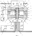
на фиг.1 приведена схема газотурбовоза,figure 1 shows a diagram of a gas turbine locomotive,
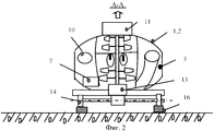
на фиг.2 - вид А-А,figure 2 is a view aa,
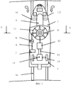
на фиг.3 приведена схема основной силовой установки газотурбовоза.figure 3 shows a diagram of the main power plant of a gas turbine locomotive.
Газотурбовоз 1 содержит корпус 2, состоящий из боковых стенок 3 и крышки 4.Gas turbine 1 contains a housing 2, consisting of
Корпус 2 установлен на шасси 5. В центральной части корпуса 2 установлена основная силовая установка 6 и вспомогательный дизель 7, соединенные между собой через муфту 8 соединительным валом 9. Два воздухозаборника 10 выполнены в передней части боковых стенок корпуса 2, на крылышке 4 установлена выхлопная труба 11. Электрогенератор 12 соединен механически с основной силовой установкой 6. Электрическая часть электрогенератора 12 соединена с тяговыми приводами 13 колесных пар 14 при помощи кабелей 15. Электрогенератор 12 находится в воздухозаборнике 10, что улучает его охлаждение. Для более эффективного охлаждения электрогенератора на его поверхности следует выполнить оребрение. Кроме того, регенерация части тепла на входе в основную силовую установку повысит ее КПД на 3…5%. Шасси 5 при помощи колесных пар 14 установлено на рельсах 16.The body 2 is mounted on the
Основная силовая установка 6 (фиг.2) содержит входное устройство 17 и два турбокомпрессора: первый - 18 и второй - 19, выполненных по биротативной схеме, т.е. без сопловых и направляющих аппаратов, с возможностью вращения в противоположные стороны. Турбокомпрессор 18 содержит компрессор низкого давления 20 и турбину низкого давления 21. Компрессор низкого давления 20 содержит по меньшей мере одно рабочее колесо компрессора 22. Турбина низкого давления 21 содержит по меньшей мере одно рабочее колесо турбины 23. Рабочие колеса компрессора 22 и рабочее колесо (колеса) турбины 23 соединены внутренним валом 24 первого турбокомпрессора 18. Второй турбокомпрессор 19 содержит компрессор высокого давления 25 и турбину высокого давления 26. Компрессор высокого давления 25 содержит, по меньшей мере, одно рабочее колесо компрессора 22, а турбина высокого давления 25 содержит, по меньшей мере, одно рабочее колесо турбины 23. Рабочее колесо (колеса) 22 компрессора высокого давления 25 и рабочее колесо (колеса) 22 турбины высокого давления 26 соединены внешним валом 27. Валы 24 и 27 установлены на подшипниках 28. Двигатель имеет внешний корпус 29, к которому крепится камера сгорания 30 с форсунками 31, к внешнему корпусу 30 также крепятся входное устройство 17 при помощи ребер 32 и реактивное сопло 33 при помощи ребер 34. Перед камерой сгорания 30 установлен спрямляющий направляющий аппарат 35.The main power plant 6 (Fig. 2) contains an
Топливная система основной силовой установки 6 содержит топливопровод 36, в котором установлен топливный насос 37, соединенный с приводом 38. Основная силовая установка 6 установлена вертикально в центре корпуса 2 газотурбовоза (локомотива) 1 (фиг.1 и 2).The fuel system of the
При работе сначала запускают вспомогательный дизель 7, потом основную силовую установку 6 при помощи вспомогательного дизеля 7, выполняющего функцию стартера, раскручивают один из турбокомпрессоров 18 или 19, запускают привод 38, который раскручивает топливный насос 37, топливо (сжиженный природный газ - СПГ) по топливопроводу 36 подается в форсунки 31 камеры сгорания 30, где воспламеняется при помощи пирозапальника или электрозапальника (не показан). Продукты сгорания проходят через турбину высокого давления 26 и турбину низкого давления 21. Мощность с турбин 21 и 26 передается на компрессоры 20 и 25, которые сжимают воздух, идущий в камеру сгорания 30. Электрогенератор 12 вырабатывает электрический ток, который по кабелю 15 подается на тяговые приводы 13, колесные пары, оборудованные этими приводами, создают тягу газотурбовоза (локомотива) 1.During operation, the
Применение изобретения позволило:The application of the invention allowed:
1. Повысить надежность локомотива за счет связи при помощи трансмиссии двух двигательных установок: основной силовой и вспомогательного дизеля, и обеспечить возможность продолжения движения при отказе одной из них.1. To increase the reliability of the locomotive through communication with the transmission of two propulsion systems: the main power and auxiliary diesel, and to ensure the possibility of continued movement in case of failure of one of them.
2. Обеспечить маневрирование газотурбовоза с применением вспомогательного дизеля.2. To provide maneuvering of a gas turbo locomotive using an auxiliary diesel engine.
3. Повысить КПД всех двигательных силовых установок за счет более рациональной компоновки всех силовых установок, наличия двух каскадов компрессора и турбины у всех силовых установок и регенерации тепла на входе в основную силовую установку. Особенно значительно улучшены тяговые и весовые характеристики и уменьшен осевой габарит основной силовой установки локомотива счет применения биротативной схемы.3. To increase the efficiency of all propulsion systems due to a more rational layout of all propulsion systems, the presence of two stages of a compressor and a turbine for all propulsion systems, and heat recovery at the entrance to the main power plant. The traction and weight characteristics are especially significantly improved and the axial dimension of the main power plant of the locomotive is reduced due to the use of a biotic scheme.
4. Облегчить запуск за счет раскрутки только одного ротора основной силовой установки без раскручивания другого ротора.4. Facilitate starting by promoting only one rotor of the main power plant without unwinding the other rotor.
5. Облегчить условия работы роторов основной силовой установки за счет отсутствия его механической связи с валами турбокомпрессоров и возможности их взаимного проскальзывания и работы на различающихся частотах вращения.5. To facilitate the working conditions of the rotors of the main power plant due to the lack of its mechanical connection with the shafts of the turbocompressors and the possibility of their mutual slippage and operation at different speeds.
6. Уменьшить вес и габариты основной силовой установки, особенно осевой габарит, что важно для газотурбовоза при вертикальном расположении основной силовой установки за счет применения биротативной схемы.6. To reduce the weight and dimensions of the main power plant, especially the axial dimension, which is important for a gas turbine locomotive with a vertical layout of the main power plant due to the use of a biotic scheme.
7. Обеспечить противоположное вращение ступеней роторов основной силовой установки без применения редуктора.7. Ensure the opposite rotation of the stages of the rotors of the main power plant without the use of a gearbox.
8. Обеспечить эффективное расположение электрогенератора за счет его расположения в воздухозаборнике.8. Ensure the effective location of the generator due to its location in the air intake.
Claims (6)
Priority Applications (1)
| Application Number | Priority Date | Filing Date | Title |
|---|---|---|---|
| RU2008112021/11A RU2374103C1 (en) | 2008-03-28 | 2008-03-28 | Gas turbine locomotive and principal power plant of gas turbine locomotive |
Applications Claiming Priority (1)
| Application Number | Priority Date | Filing Date | Title |
|---|---|---|---|
| RU2008112021/11A RU2374103C1 (en) | 2008-03-28 | 2008-03-28 | Gas turbine locomotive and principal power plant of gas turbine locomotive |
Publications (1)
| Publication Number | Publication Date |
|---|---|
| RU2374103C1 true RU2374103C1 (en) | 2009-11-27 |
Family
ID=41476598
Family Applications (1)
| Application Number | Title | Priority Date | Filing Date |
|---|---|---|---|
| RU2008112021/11A RU2374103C1 (en) | 2008-03-28 | 2008-03-28 | Gas turbine locomotive and principal power plant of gas turbine locomotive |
Country Status (1)
| Country | Link |
|---|---|
| RU (1) | RU2374103C1 (en) |
Citations (3)
| Publication number | Priority date | Publication date | Assignee | Title |
|---|---|---|---|---|
| US3543685A (en) * | 1968-05-16 | 1970-12-01 | Jan J Rosciszewski | Ground oriented vehicle with reaction type propulsion |
| EP1340903A2 (en) * | 2002-03-01 | 2003-09-03 | General Electric Company | Counter rotating aircraft gas turbine engine |
| RU2272916C2 (en) * | 2004-03-22 | 2006-03-27 | Владимир Леонидович Письменный | Steam-gas turbine plant |
-
2008
- 2008-03-28 RU RU2008112021/11A patent/RU2374103C1/en active
Patent Citations (3)
| Publication number | Priority date | Publication date | Assignee | Title |
|---|---|---|---|---|
| US3543685A (en) * | 1968-05-16 | 1970-12-01 | Jan J Rosciszewski | Ground oriented vehicle with reaction type propulsion |
| EP1340903A2 (en) * | 2002-03-01 | 2003-09-03 | General Electric Company | Counter rotating aircraft gas turbine engine |
| RU2272916C2 (en) * | 2004-03-22 | 2006-03-27 | Владимир Леонидович Письменный | Steam-gas turbine plant |
Non-Patent Citations (1)
| Title |
|---|
| Бартош Е.Т. Газотурбовозы и турбопоезда. - М.: Транспорт, 1978, с.227-230. * |
Similar Documents
| Publication | Publication Date | Title |
|---|---|---|
| US11008938B2 (en) | Gas turbine blower/pump | |
| CN103608567B (en) | For the turbine plant of locomotive | |
| CN201428517Y (en) | Auxiliary power device | |
| US10907640B2 (en) | Gas turbine blower/pump | |
| CN108533387A (en) | A kind of turbo charging installation of translator/generator | |
| RU2374103C1 (en) | Gas turbine locomotive and principal power plant of gas turbine locomotive | |
| RU2380249C2 (en) | Gas turbine locomotive | |
| RU2371336C1 (en) | Gas turbine locomotive | |
| CN113756900A (en) | Internal and external mixed combustion engine | |
| RU2334892C1 (en) | Turboprop gas turbine engine | |
| RU2380250C2 (en) | Gas turbine locomotive | |
| RU2381932C2 (en) | Gas turbine locomotive | |
| KR102566355B1 (en) | Gas Turbine Blower/Pump | |
| RU2374105C1 (en) | Gas turbine locomotive and its power plant | |
| RU2359132C1 (en) | Turboprop gas turbine engine | |
| RU2358120C1 (en) | Turbopropeller gas-turbine engine | |
| RU2374104C1 (en) | Gas turbine locomotive and its power plant | |
| RU2376484C1 (en) | Gas turbine locomotive | |
| RU2363604C1 (en) | Gas turbine locomotive and its power plant | |
| RU2314220C1 (en) | Railway train | |
| RU2334114C1 (en) | Gas turbine vehicle propulsion unit | |
| RU2312239C1 (en) | Power plant of gas-turbine locomotive | |
| RU2334885C1 (en) | Heat-recovery gas turbine power plant | |
| RU2334887C1 (en) | Heat-recovery cooled gas turbine power plant | |
| RU2319024C1 (en) | Gas turbine locomotive |